EP2363514A1 - Printed masking process by chemical milling and apparatus thereof - Google Patents
Printed masking process by chemical milling and apparatus thereof Download PDFInfo
- Publication number
- EP2363514A1 EP2363514A1 EP11156377A EP11156377A EP2363514A1 EP 2363514 A1 EP2363514 A1 EP 2363514A1 EP 11156377 A EP11156377 A EP 11156377A EP 11156377 A EP11156377 A EP 11156377A EP 2363514 A1 EP2363514 A1 EP 2363514A1
- Authority
- EP
- European Patent Office
- Prior art keywords
- workpiece
- masking
- portions
- milling
- depositing
- Prior art date
- Legal status (The legal status is an assumption and is not a legal conclusion. Google has not performed a legal analysis and makes no representation as to the accuracy of the status listed.)
- Ceased
Links
Images
Classifications
-
- B—PERFORMING OPERATIONS; TRANSPORTING
- B44—DECORATIVE ARTS
- B44C—PRODUCING DECORATIVE EFFECTS; MOSAICS; TARSIA WORK; PAPERHANGING
- B44C1/00—Processes, not specifically provided for elsewhere, for producing decorative surface effects
- B44C1/22—Removing surface-material, e.g. by engraving, by etching
- B44C1/227—Removing surface-material, e.g. by engraving, by etching by etching
-
- B—PERFORMING OPERATIONS; TRANSPORTING
- B33—ADDITIVE MANUFACTURING TECHNOLOGY
- B33Y—ADDITIVE MANUFACTURING, i.e. MANUFACTURING OF THREE-DIMENSIONAL [3D] OBJECTS BY ADDITIVE DEPOSITION, ADDITIVE AGGLOMERATION OR ADDITIVE LAYERING, e.g. BY 3D PRINTING, STEREOLITHOGRAPHY OR SELECTIVE LASER SINTERING
- B33Y30/00—Apparatus for additive manufacturing; Details thereof or accessories therefor
-
- C—CHEMISTRY; METALLURGY
- C23—COATING METALLIC MATERIAL; COATING MATERIAL WITH METALLIC MATERIAL; CHEMICAL SURFACE TREATMENT; DIFFUSION TREATMENT OF METALLIC MATERIAL; COATING BY VACUUM EVAPORATION, BY SPUTTERING, BY ION IMPLANTATION OR BY CHEMICAL VAPOUR DEPOSITION, IN GENERAL; INHIBITING CORROSION OF METALLIC MATERIAL OR INCRUSTATION IN GENERAL
- C23F—NON-MECHANICAL REMOVAL OF METALLIC MATERIAL FROM SURFACE; INHIBITING CORROSION OF METALLIC MATERIAL OR INCRUSTATION IN GENERAL; MULTI-STEP PROCESSES FOR SURFACE TREATMENT OF METALLIC MATERIAL INVOLVING AT LEAST ONE PROCESS PROVIDED FOR IN CLASS C23 AND AT LEAST ONE PROCESS COVERED BY SUBCLASS C21D OR C22F OR CLASS C25
- C23F1/00—Etching metallic material by chemical means
- C23F1/02—Local etching
- C23F1/04—Chemical milling
-
- C—CHEMISTRY; METALLURGY
- C23—COATING METALLIC MATERIAL; COATING MATERIAL WITH METALLIC MATERIAL; CHEMICAL SURFACE TREATMENT; DIFFUSION TREATMENT OF METALLIC MATERIAL; COATING BY VACUUM EVAPORATION, BY SPUTTERING, BY ION IMPLANTATION OR BY CHEMICAL VAPOUR DEPOSITION, IN GENERAL; INHIBITING CORROSION OF METALLIC MATERIAL OR INCRUSTATION IN GENERAL
- C23F—NON-MECHANICAL REMOVAL OF METALLIC MATERIAL FROM SURFACE; INHIBITING CORROSION OF METALLIC MATERIAL OR INCRUSTATION IN GENERAL; MULTI-STEP PROCESSES FOR SURFACE TREATMENT OF METALLIC MATERIAL INVOLVING AT LEAST ONE PROCESS PROVIDED FOR IN CLASS C23 AND AT LEAST ONE PROCESS COVERED BY SUBCLASS C21D OR C22F OR CLASS C25
- C23F1/00—Etching metallic material by chemical means
- C23F1/08—Apparatus, e.g. for photomechanical printing surfaces
-
- F—MECHANICAL ENGINEERING; LIGHTING; HEATING; WEAPONS; BLASTING
- F04—POSITIVE - DISPLACEMENT MACHINES FOR LIQUIDS; PUMPS FOR LIQUIDS OR ELASTIC FLUIDS
- F04D—NON-POSITIVE-DISPLACEMENT PUMPS
- F04D29/00—Details, component parts, or accessories
- F04D29/02—Selection of particular materials
- F04D29/023—Selection of particular materials especially adapted for elastic fluid pumps
-
- F—MECHANICAL ENGINEERING; LIGHTING; HEATING; WEAPONS; BLASTING
- F04—POSITIVE - DISPLACEMENT MACHINES FOR LIQUIDS; PUMPS FOR LIQUIDS OR ELASTIC FLUIDS
- F04D—NON-POSITIVE-DISPLACEMENT PUMPS
- F04D29/00—Details, component parts, or accessories
- F04D29/40—Casings; Connections of working fluid
- F04D29/52—Casings; Connections of working fluid for axial pumps
- F04D29/522—Casings; Connections of working fluid for axial pumps especially adapted for elastic fluid pumps
-
- F—MECHANICAL ENGINEERING; LIGHTING; HEATING; WEAPONS; BLASTING
- F05—INDEXING SCHEMES RELATING TO ENGINES OR PUMPS IN VARIOUS SUBCLASSES OF CLASSES F01-F04
- F05D—INDEXING SCHEME FOR ASPECTS RELATING TO NON-POSITIVE-DISPLACEMENT MACHINES OR ENGINES, GAS-TURBINES OR JET-PROPULSION PLANTS
- F05D2230/00—Manufacture
- F05D2230/20—Manufacture essentially without removing material
-
- F—MECHANICAL ENGINEERING; LIGHTING; HEATING; WEAPONS; BLASTING
- F05—INDEXING SCHEMES RELATING TO ENGINES OR PUMPS IN VARIOUS SUBCLASSES OF CLASSES F01-F04
- F05D—INDEXING SCHEME FOR ASPECTS RELATING TO NON-POSITIVE-DISPLACEMENT MACHINES OR ENGINES, GAS-TURBINES OR JET-PROPULSION PLANTS
- F05D2230/00—Manufacture
- F05D2230/50—Building or constructing in particular ways
- F05D2230/53—Building or constructing in particular ways by integrally manufacturing a component, e.g. by milling from a billet or one piece construction
Definitions
- This disclosure relates to milling, and more particularly to a printed masking process that may be used to perform chemical milling.
- Chemical milling is performed to remove undesired material from a workpiece to form channels or patterns, for example.
- Chemical milling typically involves masking an entire workpiece, etching a pattern onto the masking, using a scalpel to manually remove portions of the masking according to the etching and dipping the workpiece in a chemical bath to remove material from the unmasked portions of the workpiece.
- a method of chemically milling a workpiece includes depositing a masking material on portions of the workpiece according to a predefined masking pattern such that other portions of the workpiece that are desired to be milled are unmasked. Material from the unmasked desired milling areas of the workpiece is chemically removed.
- a system for milling a workpiece includes a computer having a storage module that stores at least one predefined masking pattern, and a three dimensional masking printer in communication with the computer.
- the masking printer is operable to apply masking material to portions of a workpiece according to the at least one predefined masking pattern such that other portions of the workpiece that are desired to be milled are unmasked.
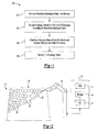
- Figure 1 schematically illustrates a method 100 of chemically milling a workpiece
- Figure 2 schematically illustrates a system 10 for performing the method 100.
- the method 100 may be used in conjunction with the system 10 to chemically mill or etch a workpiece to product an isogrid rib formation on a duct, or to produce raised lettering on a sign, for example.
- the system 10 includes a computer 12 having a CPU 14, a storage module 16, and an input/output (“I/O") module 18.
- the storage module 16 could include, for example, memory, hard drives, or any electronic, optical, magnetic or other type of computer storage.
- At least one predefined masking pattern is stored in the storage module 16.
- the at least one predefined masking pattern is retrieved from the storage module 16 (step 102).
- the at least one predefined masking pattern includes one or more computer-aided design ("CAD”) models.
- CAD computer-aided design
- a three-dimensional masking printer 20 is in communication with the computer 12.
- the masking printer 20 deposits a masking material 22 onto portions of the workpiece 24 according to the at least one masking pattern (step 104).
- the masking printer 20 is movable in three dimensions, and is operable to deposit the masking material 22 onto the workpiece 24.
- the masking material 22 is an elastomer dissolved in at least one organic solvent.
- the at least one organic solvent is selected from a group consisting of toluene, xylene, perchloroethylene, and combinations thereof. Of course, other masking materials could be used.
- step 106 includes applying chemicals to the workpiece 24, such as in a chemical bath.
- the chemicals applied to the workpiece in step 106 include an aqueous solution of acid such as ferric chloride. Of course, other milling chemicals could be used.
- An amount of material that is chemically removed from the workpiece 24 in step 106 may be controlled by adjusting the duration of the chemical bath.
- step 108 includes a power washing process that sprays the masking material off.
- the method 100 facilitates removing the human error component, using less masking material, reducing cost and improving efficiency and accuracy.
- the method 100 is widely applicable to many applications in which chemical milling or machining is desired.
- the workpiece 24 is a duct for a gas turbine engine that may be used to contain high pressure gases within the gas turbine engine.
- the method 100 may be used to form an elevated isogrid 30 on the duct, with the elevated isogrid 30, an inside 34 of the duct, and flanges 36 corresponding to the masked areas of step 104.
- the elevated isogrid 30 pattern may be chosen because it can build structural strength on the duct. Of course, other patterns could be used.
- the method 100 is applicable to other types of workpieces or substrates.
- the workpiece could be a sign, a medical device, a body of a component, a coating, a fuel cell, a heat sink, a sensor, or any other component that would benefit from precision chemical milling or machining.
Landscapes
- Engineering & Computer Science (AREA)
- Chemical & Material Sciences (AREA)
- Mechanical Engineering (AREA)
- Materials Engineering (AREA)
- General Engineering & Computer Science (AREA)
- Chemical Kinetics & Catalysis (AREA)
- General Chemical & Material Sciences (AREA)
- Metallurgy (AREA)
- Organic Chemistry (AREA)
- Manufacturing & Machinery (AREA)
- ing And Chemical Polishing (AREA)
Abstract
Description
- This disclosure relates to milling, and more particularly to a printed masking process that may be used to perform chemical milling. Chemical milling is performed to remove undesired material from a workpiece to form channels or patterns, for example. Chemical milling typically involves masking an entire workpiece, etching a pattern onto the masking, using a scalpel to manually remove portions of the masking according to the etching and dipping the workpiece in a chemical bath to remove material from the unmasked portions of the workpiece.
- A method of chemically milling a workpiece includes depositing a masking material on portions of the workpiece according to a predefined masking pattern such that other portions of the workpiece that are desired to be milled are unmasked. Material from the unmasked desired milling areas of the workpiece is chemically removed.
- A system for milling a workpiece includes a computer having a storage module that stores at least one predefined masking pattern, and a three dimensional masking printer in communication with the computer. The masking printer is operable to apply masking material to portions of a workpiece according to the at least one predefined masking pattern such that other portions of the workpiece that are desired to be milled are unmasked.
- These and other features of the present invention can be best understood from the following specification and drawings, the following of which is a brief description.
-
-
Figure 1 schematically illustrates a method of chemically milling a workpiece. -
Figure 2 schematically illustrates a system operable to perform the method ofFigure 1 . -
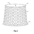
Figure 3 schematically illustrates an example chemically milled workpiece. -
Figure 1 schematically illustrates amethod 100 of chemically milling a workpiece, andFigure 2 schematically illustrates asystem 10 for performing themethod 100. Themethod 100 may be used in conjunction with thesystem 10 to chemically mill or etch a workpiece to product an isogrid rib formation on a duct, or to produce raised lettering on a sign, for example. - The
system 10 includes acomputer 12 having aCPU 14, astorage module 16, and an input/output ("I/O")module 18. Thestorage module 16 could include, for example, memory, hard drives, or any electronic, optical, magnetic or other type of computer storage. At least one predefined masking pattern is stored in thestorage module 16. The at least one predefined masking pattern is retrieved from the storage module 16 (step 102). In one example the at least one predefined masking pattern includes one or more computer-aided design ("CAD") models. - A three-
dimensional masking printer 20 is in communication with thecomputer 12. Themasking printer 20 deposits a maskingmaterial 22 onto portions of theworkpiece 24 according to the at least one masking pattern (step 104). Themasking printer 20 is movable in three dimensions, and is operable to deposit themasking material 22 onto theworkpiece 24. In one example themasking material 22 is an elastomer dissolved in at least one organic solvent. In one example, the at least one organic solvent is selected from a group consisting of toluene, xylene, perchloroethylene, and combinations thereof. Of course, other masking materials could be used. - Once the predefined pattern has been formed on the
workpiece 24, material from the unmasked desiredmilling areas 26 of theworkpiece 24 is chemically removed (step 106). In one example,step 106 includes applying chemicals to theworkpiece 24, such as in a chemical bath. In one example the chemicals applied to the workpiece instep 106 include an aqueous solution of acid such as ferric chloride. Of course, other milling chemicals could be used. An amount of material that is chemically removed from theworkpiece 24 instep 106 may be controlled by adjusting the duration of the chemical bath. - Once a desired amount of material has been chemically removed from the unmasked areas, the masking material may be removed (step 108). In one example,
step 108 includes a power washing process that sprays the masking material off. - Unlike masking an entire workpiece and then manually removing maskant by hand with a scalpel, which is a labor-intensive and error prone process, the
method 100 facilitates removing the human error component, using less masking material, reducing cost and improving efficiency and accuracy. - The
method 100 is widely applicable to many applications in which chemical milling or machining is desired. For example, as shown inFigures 2-3 , theworkpiece 24 is a duct for a gas turbine engine that may be used to contain high pressure gases within the gas turbine engine. Themethod 100 may be used to form anelevated isogrid 30 on the duct, with the elevatedisogrid 30, aninside 34 of the duct, andflanges 36 corresponding to the masked areas ofstep 104. The elevatedisogrid 30 pattern may be chosen because it can build structural strength on the duct. Of course, other patterns could be used. - Also, although a duct for a gas turbine engine has been illustrated, the
method 100 is applicable to other types of workpieces or substrates. For example, the workpiece could be a sign, a medical device, a body of a component, a coating, a fuel cell, a heat sink, a sensor, or any other component that would benefit from precision chemical milling or machining. - Although embodiments have been disclosed, a worker of ordinary skill in this art would recognize that certain modifications would come within the scope of this disclosure. For that reason, the following claims should be studied to determine the true scope and content of this invention.
Claims (15)
- A method (100) of chemically milling a workpiece (24), comprising:depositing (104) a masking material (22) on portions of the workpiece (24) according to a predefined masking pattern such that other portions (26) of the workpiece (24) that are desired to be milled are unmasked; andchemically removing (106) material from the unmasked desired milling areas (26) of the workpiece (24).
- The method of claim 1, wherein the masking material is deposited using a three-dimensional masking printer (20).
- The method of claim 1 or 2, including:removing the masking pattern from the masked portions of the workpiece (24).
- The method of any preceding claim, wherein said depositing (104) a masking material (22) on portions of the workpiece includes:depositing the masking material (22) on a curved surface of the workpiece (24).
- The method of any preceding claim, wherein said depositing (104) a masking material (24) on portions of the workpiece (24) includes:depositing the masking material (22) in an isogrid pattern on portions of the workpiece (24).
- The method of any preceding claim, wherein said depositing (104) a masking material (22) on portions of the workpiece (24) includes:depositing an elastomer dissolved in at least one organic solvent on portions of the workpiece (24).
- The method of claim 6, wherein said at least one organic solvent is selected from a group consisting of toluene, xylene, perchloroethylene, and combinations thereof.
- The method of any preceding claim, wherein said chemically removing (106) material from the unmasked desired milling areas (26) of the workpiece (24) includes subjecting the workpiece (24) to a chemical bath that includes an aqueous solution of acid.
- The method of claim 8, wherein the acid includes ferric chloride.
- A system (10) for milling a workpiece, comprising:a computer (12) having a storage module (16) that stores at least one predefined masking pattern; anda three dimensional masking printer (20) in communication with the computer (12), the masking printer (20) being operable to apply masking material (22) to portions of a workpiece (24) according to the at least one predefined masking pattern such that other portions (26) of the workpiece (24) that are desired to be milled are unmasked.
- The system of claim 10, including:a milling chemical operable to remove portions of the surface of the unmasked desired milling areas;a chemical bath in which the milling chemical is applied to the workpiece, the chemical bath including an aqueous solution of acid.
- The system of claim 10 or 11, wherein the masking material (22) includes an elastomer dissolved in at least one organic solvent.
- The system of claim 12, wherein the at least one organic solvent is selected from a group consisting of toluene, xylene, perchloroethylene, and combinations thereof.
- The system of any of claims 10 to 13, wherein the at least one predefined masking pattern includes an isogrid pattern.
- The system or method of any preceding claim, wherein the workpiece (24) is a duct for a gas turbine engine.
Applications Claiming Priority (1)
| Application Number | Priority Date | Filing Date | Title |
|---|---|---|---|
| US12/714,638 US8257600B2 (en) | 2010-03-01 | 2010-03-01 | Printed masking process |
Publications (1)
| Publication Number | Publication Date |
|---|---|
| EP2363514A1 true EP2363514A1 (en) | 2011-09-07 |
Family
ID=43902933
Family Applications (1)
| Application Number | Title | Priority Date | Filing Date |
|---|---|---|---|
| EP11156377A Ceased EP2363514A1 (en) | 2010-03-01 | 2011-03-01 | Printed masking process by chemical milling and apparatus thereof |
Country Status (2)
| Country | Link |
|---|---|
| US (2) | US8257600B2 (en) |
| EP (1) | EP2363514A1 (en) |
Cited By (1)
| Publication number | Priority date | Publication date | Assignee | Title |
|---|---|---|---|---|
| WO2016108053A1 (en) * | 2014-12-29 | 2016-07-07 | Informativni Kamen J.D.O.O. | Stone engraving process by etching enhanced by computer preparation |
Families Citing this family (12)
| Publication number | Priority date | Publication date | Assignee | Title |
|---|---|---|---|---|
| US20160047029A1 (en) * | 2013-03-15 | 2016-02-18 | Aeromet Technologies, Inc. | Method and Apparatus for Depositing Protective Coatings and Components Coated Thereby |
| US9289917B2 (en) | 2013-10-01 | 2016-03-22 | General Electric Company | Method for 3-D printing a pattern for the surface of a turbine shroud |
| US9815227B2 (en) | 2014-01-07 | 2017-11-14 | United Technologies Corporation | Media containment for iso-grid structure forming |
| DE102014207507B4 (en) | 2014-04-17 | 2021-12-16 | Kennametal Inc. | Cutting tool and method for producing a cutting tool |
| DE102014207510B4 (en) | 2014-04-17 | 2021-12-16 | Kennametal Inc. | Cutting tool and method for producing a cutting tool |
| US9643282B2 (en) | 2014-10-17 | 2017-05-09 | Kennametal Inc. | Micro end mill and method of manufacturing same |
| CN108291036A (en) | 2015-12-01 | 2018-07-17 | 金伯利-克拉克环球有限公司 | Absorbent and protective compositions comprising elastomeric copolymers |
| US11142830B2 (en) | 2019-02-08 | 2021-10-12 | The Boeing Company | Method of surface micro-texturing with a subtractive agent |
| US11136673B2 (en) * | 2019-02-08 | 2021-10-05 | The Boeing Company | Method of surface micro-texturing with a subtractive agent |
| US11623758B2 (en) * | 2020-03-02 | 2023-04-11 | Textron Innovations Inc. | Lattice structure cushions for aircraft fuel systems |
| CN113275563B (en) * | 2021-04-28 | 2022-03-15 | 北京航空航天大学 | A method for preparing sensor mask on turbine blade surface |
| US11982200B1 (en) | 2023-06-23 | 2024-05-14 | Pratt & Whitney Canada Corp. | Structure with structural reinforcement patterns |
Citations (16)
| Publication number | Priority date | Publication date | Assignee | Title |
|---|---|---|---|---|
| US2739047A (en) * | 1953-10-30 | 1956-03-20 | North American Aviation Inc | Process of chemically milling structural shapes and resultant article |
| US2881059A (en) * | 1956-03-02 | 1959-04-07 | North American Aviation Inc | Chemical taper milling process |
| US3061494A (en) * | 1959-10-05 | 1962-10-30 | Boeing Co | Process of chemical milling and acid aqueous bath used therefor |
| US3380863A (en) * | 1966-03-31 | 1968-04-30 | Purex Corp Ltd | Method of etching with a strippable maskant |
| US4137118A (en) * | 1977-04-06 | 1979-01-30 | Chem-Tronics, Inc. | Chemical milling apparatus |
| US4523973A (en) * | 1983-10-17 | 1985-06-18 | Aerochem, Inc. | Method and apparatus for automated chemical milling of compound curved surfaces |
| US4716270A (en) * | 1985-11-04 | 1987-12-29 | Rockwell International Corporation | Non-contact scribing process for organic maskants on metals or alloys thereof |
| US4921565A (en) * | 1989-04-28 | 1990-05-01 | Paul Slysh | Parts orbiter for chem-milling vat |
| US5122242A (en) * | 1990-11-13 | 1992-06-16 | Paul Slysh | Electrochemical machining process |
| WO1996000315A1 (en) * | 1994-06-27 | 1996-01-04 | Melanesia International Trust Company Limited | Chemical milling apparatus and method |
| US5951882A (en) * | 1993-09-30 | 1999-09-14 | Parker Intangibles Inc. | Spray nozzle and method of manufacturing same |
| EP1239059A2 (en) * | 2001-03-07 | 2002-09-11 | General Electric Company | Chemical milling of the blades of a gas turbine engine |
| EP1356892A1 (en) * | 2002-04-22 | 2003-10-29 | ROLLS-ROYCE plc | Method of manufacturing thin wall isogrid casings |
| JP2006098982A (en) * | 2004-09-30 | 2006-04-13 | Hitachi Chem Co Ltd | Photosensitive film and method for producing printed wiring board using the same |
| EP1752563A2 (en) * | 2005-08-12 | 2007-02-14 | United Technologies Corporation | Masking techniques for electrochemical stripping |
| US20080264897A1 (en) * | 2007-04-30 | 2008-10-30 | Canan Uslu Hardwicke | Turbine component pattern forming method |
Family Cites Families (17)
| Publication number | Priority date | Publication date | Assignee | Title |
|---|---|---|---|---|
| US2940838A (en) * | 1957-08-19 | 1960-06-14 | Boeing Co | Chemical milling |
| US3227589A (en) * | 1963-06-12 | 1966-01-04 | Organo Cerams Inc | Method of chemically milling a metallic workpiece |
| US4155801A (en) * | 1977-10-27 | 1979-05-22 | Rohr Industries, Inc. | Process for masking sheet metal for chemical milling |
| US4301194A (en) * | 1979-05-04 | 1981-11-17 | Purex Corporation | Chemical milling maskant application process |
| US4401367A (en) * | 1980-11-03 | 1983-08-30 | United Technologies Corporation | Method for pattern masking objects and the products thereof |
| US4585519A (en) * | 1983-02-10 | 1986-04-29 | Grumman Aerospace Corporation | Automated chemical milling process |
| US5173392A (en) * | 1989-08-28 | 1992-12-22 | International Business Machines, Corp. | Forming a pattern on a substrate |
| US5238752A (en) | 1990-05-07 | 1993-08-24 | General Electric Company | Thermal barrier coating system with intermetallic overlay bond coat |
| US6107004A (en) * | 1991-09-05 | 2000-08-22 | Intra Therapeutics, Inc. | Method for making a tubular stent for use in medical applications |
| RU2168558C2 (en) * | 1995-07-25 | 2001-06-10 | Сименс Акциенгезелльшафт | Article with metal main body and process of its manufacture |
| US5565035A (en) * | 1996-03-14 | 1996-10-15 | United Technologies Corporation | Fixture for masking a portion of an airfoil during application of a coating |
| US6273676B1 (en) * | 1998-06-17 | 2001-08-14 | United Technologies Corporation | Method and assembly for masking a flow directing assembly |
| EP1033417A1 (en) | 1999-03-04 | 2000-09-06 | Siemens Aktiengesellschaft | Process and apparatus for coating a product, especially a high temperature gas turbine component |
| US6296705B1 (en) * | 1999-12-15 | 2001-10-02 | United Technologies Corporation | Masking fixture and method |
| US8178188B2 (en) * | 2001-04-20 | 2012-05-15 | Panasonic Corporation | Base layer for manufacturing an electronic component by an etching process |
| US6689487B2 (en) | 2001-12-21 | 2004-02-10 | Howmet Research Corporation | Thermal barrier coating |
| US20070089625A1 (en) * | 2005-10-20 | 2007-04-26 | Elbit Vision Systems Ltd. | Method and system for detecting defects during the fabrication of a printing cylinder |
-
2010
- 2010-03-01 US US12/714,638 patent/US8257600B2/en active Active
-
2011
- 2011-03-01 EP EP11156377A patent/EP2363514A1/en not_active Ceased
-
2012
- 2012-08-20 US US13/589,385 patent/US8728336B2/en active Active
Patent Citations (16)
| Publication number | Priority date | Publication date | Assignee | Title |
|---|---|---|---|---|
| US2739047A (en) * | 1953-10-30 | 1956-03-20 | North American Aviation Inc | Process of chemically milling structural shapes and resultant article |
| US2881059A (en) * | 1956-03-02 | 1959-04-07 | North American Aviation Inc | Chemical taper milling process |
| US3061494A (en) * | 1959-10-05 | 1962-10-30 | Boeing Co | Process of chemical milling and acid aqueous bath used therefor |
| US3380863A (en) * | 1966-03-31 | 1968-04-30 | Purex Corp Ltd | Method of etching with a strippable maskant |
| US4137118A (en) * | 1977-04-06 | 1979-01-30 | Chem-Tronics, Inc. | Chemical milling apparatus |
| US4523973A (en) * | 1983-10-17 | 1985-06-18 | Aerochem, Inc. | Method and apparatus for automated chemical milling of compound curved surfaces |
| US4716270A (en) * | 1985-11-04 | 1987-12-29 | Rockwell International Corporation | Non-contact scribing process for organic maskants on metals or alloys thereof |
| US4921565A (en) * | 1989-04-28 | 1990-05-01 | Paul Slysh | Parts orbiter for chem-milling vat |
| US5122242A (en) * | 1990-11-13 | 1992-06-16 | Paul Slysh | Electrochemical machining process |
| US5951882A (en) * | 1993-09-30 | 1999-09-14 | Parker Intangibles Inc. | Spray nozzle and method of manufacturing same |
| WO1996000315A1 (en) * | 1994-06-27 | 1996-01-04 | Melanesia International Trust Company Limited | Chemical milling apparatus and method |
| EP1239059A2 (en) * | 2001-03-07 | 2002-09-11 | General Electric Company | Chemical milling of the blades of a gas turbine engine |
| EP1356892A1 (en) * | 2002-04-22 | 2003-10-29 | ROLLS-ROYCE plc | Method of manufacturing thin wall isogrid casings |
| JP2006098982A (en) * | 2004-09-30 | 2006-04-13 | Hitachi Chem Co Ltd | Photosensitive film and method for producing printed wiring board using the same |
| EP1752563A2 (en) * | 2005-08-12 | 2007-02-14 | United Technologies Corporation | Masking techniques for electrochemical stripping |
| US20080264897A1 (en) * | 2007-04-30 | 2008-10-30 | Canan Uslu Hardwicke | Turbine component pattern forming method |
Non-Patent Citations (1)
| Title |
|---|
| FRANCIS R G ED - NUMERICAL CONTROL SOCIETY: "THE APPLICATION OF LOW-COST CAD/CAM SYSTEMS TO THE DESIGN, MANUFACTURE AND MARKETING OF MACHINE TOOLS", NC CADCAM : THE VEHICLE TO IMPROVED PRODUCTIVITY. DEARBORN, APRIL 18 - 21 1982; [PROCEEDINGS OF THE ANNUAL MEETING AND TECHNICAL CONFERENCE], GLENVIEW, N.C.S, US, vol. PROC. 19, 1 April 1982 (1982-04-01), pages 298 - 314, XP000744666 * |
Cited By (1)
| Publication number | Priority date | Publication date | Assignee | Title |
|---|---|---|---|---|
| WO2016108053A1 (en) * | 2014-12-29 | 2016-07-07 | Informativni Kamen J.D.O.O. | Stone engraving process by etching enhanced by computer preparation |
Also Published As
| Publication number | Publication date |
|---|---|
| US8257600B2 (en) | 2012-09-04 |
| US8728336B2 (en) | 2014-05-20 |
| US20110210096A1 (en) | 2011-09-01 |
| US20130020282A1 (en) | 2013-01-24 |
Similar Documents
| Publication | Publication Date | Title |
|---|---|---|
| EP2363514A1 (en) | Printed masking process by chemical milling and apparatus thereof | |
| Hong et al. | Synergistic integrated design of an electrochemical mechanical polishing end-effector for robotic polishing applications | |
| Yang et al. | Removal and repair techniques for thermal barrier coatings: a review | |
| Tehrani et al. | A new etchant for the chemical machining of St304 | |
| Kenney et al. | Electrochemical machining with ultrashort voltage pulses: modelling of charging dynamics and feature profile evolution | |
| Çakir et al. | Chemical machining | |
| JP2004525254A5 (en) | ||
| CN110382161B (en) | Method for manufacturing engineering mask | |
| CN104018157A (en) | High-precision metal etching process | |
| Sheng et al. | Investigation on chemical etching process of FPCB with 18 μm line pitch | |
| EP3877094A1 (en) | Systems, devices, and methods for use with aerospace parts | |
| Wang et al. | Research status and prospect of laser scribing process and equipment for chemical milling parts in aviation and aerospace | |
| EP1316389A2 (en) | Method for removing a damaged region beneath a protective coating on a turbine blade | |
| US11065716B2 (en) | Method for processing, in particular separating, a substrate by means of laser-induced deep reactive etching | |
| CN111673151B (en) | Manufacturing process method for parts with plates | |
| Hung et al. | Disclosing AlN ceramic substrate process failure mode and effect analysis | |
| Yadav et al. | Experimental study on parameter evaluation of thin metal sheets using photochemical machining | |
| CN103338592A (en) | Buried resistor and manufacture process thereof | |
| CN1827862A (en) | Layered microstructure electroforming method and apparatus | |
| CN105744745A (en) | Manufacture method of multilayer FPC board | |
| EP3693617A1 (en) | Method of surface micro-texturing with a subtractive agent | |
| US20070295614A1 (en) | Method for Monitoring an Electrochemical Treatment Process and Electrode Arrangement Suited for Carrying Out This Method | |
| Ochal et al. | Investigations on changes in the surface geometrical texture caused by the use of corrosion product removers | |
| CN114248003B (en) | Micro part laser processing technique | |
| ATE542785T1 (en) | METHOD FOR ELECTROPHORETIC COATING |
Legal Events
| Date | Code | Title | Description |
|---|---|---|---|
| PUAI | Public reference made under article 153(3) epc to a published international application that has entered the european phase |
Free format text: ORIGINAL CODE: 0009012 |
|
| AK | Designated contracting states |
Kind code of ref document: A1 Designated state(s): AL AT BE BG CH CY CZ DE DK EE ES FI FR GB GR HR HU IE IS IT LI LT LU LV MC MK MT NL NO PL PT RO RS SE SI SK SM TR |
|
| AX | Request for extension of the european patent |
Extension state: BA ME |
|
| 17P | Request for examination filed |
Effective date: 20120305 |
|
| RAP1 | Party data changed (applicant data changed or rights of an application transferred) |
Owner name: UNITED TECHNOLOGIES CORPORATION |
|
| STAA | Information on the status of an ep patent application or granted ep patent |
Free format text: STATUS: EXAMINATION IS IN PROGRESS |
|
| 17Q | First examination report despatched |
Effective date: 20170717 |
|
| STAA | Information on the status of an ep patent application or granted ep patent |
Free format text: STATUS: THE APPLICATION HAS BEEN REFUSED |
|
| 18R | Application refused |
Effective date: 20191021 |