EP2363302A1 - Device for connecting a suspension element to a commercial vehicle axle - Google Patents
Device for connecting a suspension element to a commercial vehicle axle Download PDFInfo
- Publication number
- EP2363302A1 EP2363302A1 EP10015757A EP10015757A EP2363302A1 EP 2363302 A1 EP2363302 A1 EP 2363302A1 EP 10015757 A EP10015757 A EP 10015757A EP 10015757 A EP10015757 A EP 10015757A EP 2363302 A1 EP2363302 A1 EP 2363302A1
- Authority
- EP
- European Patent Office
- Prior art keywords
- axle body
- axle
- commercial vehicle
- abutment
- fixing projection
- Prior art date
- Legal status (The legal status is an assumption and is not a legal conclusion. Google has not performed a legal analysis and makes no representation as to the accuracy of the status listed.)
- Granted
Links
- 239000000725 suspension Substances 0.000 title description 3
- 210000002414 leg Anatomy 0.000 description 33
- 210000000689 upper leg Anatomy 0.000 description 3
- 230000037237 body shape Effects 0.000 description 2
- 229910001018 Cast iron Inorganic materials 0.000 description 1
- 239000006096 absorbing agent Substances 0.000 description 1
- 238000004873 anchoring Methods 0.000 description 1
- 238000005266 casting Methods 0.000 description 1
- 230000002349 favourable effect Effects 0.000 description 1
- 238000002955 isolation Methods 0.000 description 1
- 230000003716 rejuvenation Effects 0.000 description 1
- 230000035939 shock Effects 0.000 description 1
- 239000003381 stabilizer Substances 0.000 description 1
Images


Classifications
-
- B—PERFORMING OPERATIONS; TRANSPORTING
- B60—VEHICLES IN GENERAL
- B60B—VEHICLE WHEELS; CASTORS; AXLES FOR WHEELS OR CASTORS; INCREASING WHEEL ADHESION
- B60B35/00—Axle units; Parts thereof ; Arrangements for lubrication of axles
- B60B35/12—Torque-transmitting axles
- B60B35/16—Axle housings
- B60B35/163—Axle housings characterised by specific shape of the housing, e.g. adaptations to give space for other vehicle elements like chassis or exhaust system
-
- B—PERFORMING OPERATIONS; TRANSPORTING
- B60—VEHICLES IN GENERAL
- B60B—VEHICLE WHEELS; CASTORS; AXLES FOR WHEELS OR CASTORS; INCREASING WHEEL ADHESION
- B60B35/00—Axle units; Parts thereof ; Arrangements for lubrication of axles
- B60B35/003—Steerable axles
-
- B—PERFORMING OPERATIONS; TRANSPORTING
- B60—VEHICLES IN GENERAL
- B60B—VEHICLE WHEELS; CASTORS; AXLES FOR WHEELS OR CASTORS; INCREASING WHEEL ADHESION
- B60B35/00—Axle units; Parts thereof ; Arrangements for lubrication of axles
- B60B35/004—Mounting arrangements for axles
- B60B35/006—Mounting arrangements for axles with mounting plates or consoles fitted to axles
- B60B35/007—Mounting arrangements for axles with mounting plates or consoles fitted to axles for mounting suspension elements to axles
-
- B—PERFORMING OPERATIONS; TRANSPORTING
- B60—VEHICLES IN GENERAL
- B60G—VEHICLE SUSPENSION ARRANGEMENTS
- B60G11/00—Resilient suspensions characterised by arrangement, location or kind of springs
- B60G11/02—Resilient suspensions characterised by arrangement, location or kind of springs having leaf springs only
- B60G11/04—Resilient suspensions characterised by arrangement, location or kind of springs having leaf springs only arranged substantially parallel to the longitudinal axis of the vehicle
-
- B—PERFORMING OPERATIONS; TRANSPORTING
- B60—VEHICLES IN GENERAL
- B60G—VEHICLE SUSPENSION ARRANGEMENTS
- B60G11/00—Resilient suspensions characterised by arrangement, location or kind of springs
- B60G11/02—Resilient suspensions characterised by arrangement, location or kind of springs having leaf springs only
- B60G11/10—Resilient suspensions characterised by arrangement, location or kind of springs having leaf springs only characterised by means specially adapted for attaching the spring to axle or sprung part of the vehicle
- B60G11/113—Mountings on the axle
-
- B—PERFORMING OPERATIONS; TRANSPORTING
- B60—VEHICLES IN GENERAL
- B60G—VEHICLE SUSPENSION ARRANGEMENTS
- B60G9/00—Resilient suspensions of a rigid axle or axle housing for two or more wheels
-
- B—PERFORMING OPERATIONS; TRANSPORTING
- B60—VEHICLES IN GENERAL
- B60B—VEHICLE WHEELS; CASTORS; AXLES FOR WHEELS OR CASTORS; INCREASING WHEEL ADHESION
- B60B2310/00—Manufacturing methods
- B60B2310/30—Manufacturing methods joining
- B60B2310/306—Manufacturing methods joining by clamping or wedging, e.g. by clamping inserts as joining means
-
- B—PERFORMING OPERATIONS; TRANSPORTING
- B60—VEHICLES IN GENERAL
- B60G—VEHICLE SUSPENSION ARRANGEMENTS
- B60G2200/00—Indexing codes relating to suspension types
- B60G2200/30—Rigid axle suspensions
-
- B—PERFORMING OPERATIONS; TRANSPORTING
- B60—VEHICLES IN GENERAL
- B60G—VEHICLE SUSPENSION ARRANGEMENTS
- B60G2200/00—Indexing codes relating to suspension types
- B60G2200/40—Indexing codes relating to the wheels in the suspensions
- B60G2200/422—Driving wheels or live axles
-
- B—PERFORMING OPERATIONS; TRANSPORTING
- B60—VEHICLES IN GENERAL
- B60G—VEHICLE SUSPENSION ARRANGEMENTS
- B60G2202/00—Indexing codes relating to the type of spring, damper or actuator
- B60G2202/10—Type of spring
- B60G2202/11—Leaf spring
- B60G2202/112—Leaf spring longitudinally arranged
-
- B—PERFORMING OPERATIONS; TRANSPORTING
- B60—VEHICLES IN GENERAL
- B60G—VEHICLE SUSPENSION ARRANGEMENTS
- B60G2204/00—Indexing codes related to suspensions per se or to auxiliary parts
- B60G2204/10—Mounting of suspension elements
- B60G2204/12—Mounting of springs or dampers
- B60G2204/121—Mounting of leaf springs
-
- B—PERFORMING OPERATIONS; TRANSPORTING
- B60—VEHICLES IN GENERAL
- B60G—VEHICLE SUSPENSION ARRANGEMENTS
- B60G2204/00—Indexing codes related to suspensions per se or to auxiliary parts
- B60G2204/10—Mounting of suspension elements
- B60G2204/14—Mounting of suspension arms
- B60G2204/148—Mounting of suspension arms on the unsprung part of the vehicle, e.g. wheel knuckle or rigid axle
-
- B—PERFORMING OPERATIONS; TRANSPORTING
- B60—VEHICLES IN GENERAL
- B60G—VEHICLE SUSPENSION ARRANGEMENTS
- B60G2204/00—Indexing codes related to suspensions per se or to auxiliary parts
- B60G2204/40—Auxiliary suspension parts; Adjustment of suspensions
- B60G2204/43—Fittings, brackets or knuckles
- B60G2204/4306—Bracket or knuckle for rigid axles, e.g. for clamping
-
- B—PERFORMING OPERATIONS; TRANSPORTING
- B60—VEHICLES IN GENERAL
- B60G—VEHICLE SUSPENSION ARRANGEMENTS
- B60G2204/00—Indexing codes related to suspensions per se or to auxiliary parts
- B60G2204/40—Auxiliary suspension parts; Adjustment of suspensions
- B60G2204/44—Centering or positioning means
-
- B—PERFORMING OPERATIONS; TRANSPORTING
- B60—VEHICLES IN GENERAL
- B60G—VEHICLE SUSPENSION ARRANGEMENTS
- B60G2206/00—Indexing codes related to the manufacturing of suspensions: constructional features, the materials used, procedures or tools
- B60G2206/01—Constructional features of suspension elements, e.g. arms, dampers, springs
- B60G2206/30—Constructional features of rigid axles
- B60G2206/32—Hollow cross section
-
- B—PERFORMING OPERATIONS; TRANSPORTING
- B60—VEHICLES IN GENERAL
- B60G—VEHICLE SUSPENSION ARRANGEMENTS
- B60G2206/00—Indexing codes related to the manufacturing of suspensions: constructional features, the materials used, procedures or tools
- B60G2206/01—Constructional features of suspension elements, e.g. arms, dampers, springs
- B60G2206/80—Manufacturing procedures
- B60G2206/81—Shaping
- B60G2206/8101—Shaping by casting
-
- B—PERFORMING OPERATIONS; TRANSPORTING
- B60—VEHICLES IN GENERAL
- B60G—VEHICLE SUSPENSION ARRANGEMENTS
- B60G2206/00—Indexing codes related to the manufacturing of suspensions: constructional features, the materials used, procedures or tools
- B60G2206/01—Constructional features of suspension elements, e.g. arms, dampers, springs
- B60G2206/80—Manufacturing procedures
- B60G2206/81—Shaping
- B60G2206/8102—Shaping by stamping
-
- B—PERFORMING OPERATIONS; TRANSPORTING
- B60—VEHICLES IN GENERAL
- B60G—VEHICLE SUSPENSION ARRANGEMENTS
- B60G2206/00—Indexing codes related to the manufacturing of suspensions: constructional features, the materials used, procedures or tools
- B60G2206/01—Constructional features of suspension elements, e.g. arms, dampers, springs
- B60G2206/80—Manufacturing procedures
- B60G2206/82—Joining
- B60G2206/8207—Joining by screwing
-
- B—PERFORMING OPERATIONS; TRANSPORTING
- B60—VEHICLES IN GENERAL
- B60G—VEHICLE SUSPENSION ARRANGEMENTS
- B60G2300/00—Indexing codes relating to the type of vehicle
- B60G2300/02—Trucks; Load vehicles
-
- B—PERFORMING OPERATIONS; TRANSPORTING
- B60—VEHICLES IN GENERAL
- B60Y—INDEXING SCHEME RELATING TO ASPECTS CROSS-CUTTING VEHICLE TECHNOLOGY
- B60Y2200/00—Type of vehicle
- B60Y2200/10—Road Vehicles
- B60Y2200/14—Trucks; Load vehicles, Busses
-
- B—PERFORMING OPERATIONS; TRANSPORTING
- B60—VEHICLES IN GENERAL
- B60Y—INDEXING SCHEME RELATING TO ASPECTS CROSS-CUTTING VEHICLE TECHNOLOGY
- B60Y2200/00—Type of vehicle
- B60Y2200/20—Off-Road Vehicles
- B60Y2200/22—Agricultural vehicles
-
- B—PERFORMING OPERATIONS; TRANSPORTING
- B60—VEHICLES IN GENERAL
- B60Y—INDEXING SCHEME RELATING TO ASPECTS CROSS-CUTTING VEHICLE TECHNOLOGY
- B60Y2200/00—Type of vehicle
- B60Y2200/20—Off-Road Vehicles
- B60Y2200/24—Military vehicles
Definitions
- the invention relates to a utility vehicle, with an axle body according to the preamble of patent claim 1.
- axle connection for spring-mounted vehicle axles has a preferably designed as a square tube with rounded edges axle body.
- the axle connection has trailing arms or leaf springs provided, which intersect the axle body at its top or bottom.
- tie rods are arranged, which extend transversely to the trailing arms or leaf springs as well as to the axle body and pull apart said parts against each other.
- the tie rods extend along the side walls of the axle body and are supported on an outer axis of the axle abutting axles.
- the tie rods are provided along their longitudinal extent with at least one bend or offset.
- the invention has for its object to provide a spring connection to an axle body, in which the introduction of force of the spring element in the axle body runs cheaper and the structure of the axle is thereby relieved.
- the invention comprises a tensioning bridge comprising at least two legs, which are connected to one another via at least one web, wherein an axle body extends between the legs. In the installed state, the tensioning bridge spans the axle body.
- the spring element is fixed by means of clamping devices on the upper side of the web of the clamping bridge.
- the clamping devices are attached to the abutment or on the fixing projection of the axle body.
- the tensioning bridge is adapted to the outer circumference of the axle body of the commercial vehicle axle.
- the invention enables the arrangement of a standardized clamping bridge on axle bodies with different shape and deviating diameter, so that the clamping bridge can be used on axle bodies with a hollow cross-section, U-profiles or double T-profiles.
- the lists are only exemplary and in no way exclusively meant.
- the clamping bridge according to the invention can rather be combined with any possible axle body shape. It is irrelevant whether it is a driven or a non-driven axle acts.
- the tensioning bridge proves to be advantageous because it resists high vertical forces and other tasks such.
- Conceivable are z. As leaf springs, coil springs, air springs or hydropneumatic suspensions, for example in the form of hydraulic cylinders. According to the invention, the web is spaced in the installed state of the axle.
- an abutment is arranged, which spans the axle body and thereby connects the legs together.
- the abutment serves for additional anchoring of the tensioning bridge on the axle body.
- the abutment on lateral walls which extend at an angle to the base of the abutment and are connectable to the legs of the clamping bridge and / or the web of the clamping bridge.
- the abutment and the clamping bridge can be screwed together or braced.
- other connection possibilities between the abutment and the clamping bridge are possible.
- At least one centering device is provided on the abutment and / or on the clamping bridge and / or on the fixing projection, which allow a positionally accurate arrangement of the clamping bridge relative to the abutment or a positionally accurate arrangement of the clamping bridge or the abutment relative to the axle body.
- the fixing projection is arranged in the region of the zero line of the axle body, ie in the region of the smallest bend on the axle body. It is conceivable that the fixing projections are mounted horizontally or angled transversely to the direction of travel on the axle body.
- the fixing projections may be cast in one piece with the axle body or forged to the axle body.
- a vertical force emanating from the spring element is directed over the leg of the tensioning bridge into the fixing projection of the axle body.
- the back of the axle body is freed in this way from the entry of high vertical loads, since the force acting on the axle body Compressive load flows homogeneously and laterally into the axle body. Due to the fact that the legs are connected to the fixing projections, the force introduction of the spring element is not directly from above on the back of the axle body. The back of the axle body is relieved of the vertical pressure exerted by the spring element, resulting in a significant extension of the life of the axle body.
- the fixing projection wedge-shaped wherein the upper, the web of the clamping bridge facing the end of the fixing projection forms a footprint for the leg, whereas the lower end of the fixing projection to the wider lower portion of the axle body out is rejuvenated.
- a further embodiment of the invention provides that the leg lower side and the profile of the fixing projection, on which the leg rests, are designed such that a mutual engagement between the leg lower side and the fixing projection is possible. As a result, a slip-proof attachment of the carrier profile is ensured on the fixing projection.
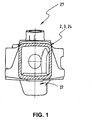
- Fig. 1 shows a connection device of a spring element (not shown) on an axle body 2 of a commercial vehicle axle 3 for vibration isolation of the chassis frame (not shown) relative to the vehicle axle 3 according to the prior art.
- the axle body 2 has an approximately rectangular shape 24, which receives the vehicle axle 3 in itself.
- With number 27 a receptacle for wheel carrier is shown.
- Fig. 2 shows in side view the axle body 2 of the commercial vehicle axle 3 with the Ausretesachskessel 22 and the Fix réellesvorsprüngen 8.
- the Fixtechniksvorsprüngen 8 and parallel to the Fix réellesvorsprüngen 8 on the axle 2 Zentrier wornen 21, 25 are provided, the positionally accurate arrangement of the clamping bridge 4 and the abutment 9 against each other and enable relative to the axle body 2.
- the axle body 2 receptacles 27 are provided for the wheel.
- the spine 10 of the axle body 2 can be seen, which is denoted by reference numeral 15 with respect to the lower region of the axle body 2.
- An imaginary line 28 runs along the fixing projection 8 and separates the axle body 2 into a back 10 and a lower region 15.
- the imaginary line 28 simultaneously marks the zero line 11, namely the region of the axle body 2 in which the bend is the smallest.
- Fig. 3 shows a section through the axle body 2 next to the clamping bridge 4 and the abutment 9 of the connection device according to the invention.
- the axle body 2 is trapezoidal and has a back 10 and a lower portion 15. in the Seen cross-section, the axle body 2 widens from the back 10 toward the lower region 15.
- the axis 3 of the utility vehicle can be seen.
- Fixianssvorsprünge 8 are attached approximately in the zero line 11 of the axle body 2 on the outer circumference of the axle body.
- the fixing protrusions 8 divide the axle body 2 into a spine 10 and a lower region 15.
- the fixing protrusion has a standing surface 30 on which the contact surface 18 of the leg 5 of the tensioning bridge 4 (not shown) is supported.
- the fixing projection 8 tapers from its upper end 16 to its lower end 17, so that the force in the downwardly widening region 15 of the axle body 2 is initiated.
- Centering 21 recognizable.
- a further centering device 25 is arranged, which serves to position the abutment 9 relative to the axle body 2.
- Fig. 4 shows an exploded view of an axle 2 with a arranged over the back 10 of the axle 2 tensioning bridge 4 and a recognizable below the axle body 2 abutment 9.
- the axle body 2 has a Ausretesachskessel 22 of the differential gear and at its outer end a receptacle 27 for the wheel ,
- the fixing projection 8 extends on the outer circumference of the axle body 2.
- the profile 14 of the fixing projection 8 shows an upper end 16 and a downwardly tapering lower end 17 and a centering device 21.
- the legs 5 of the clamping bridge 4 can be seen, between which the axle body 2 extends.
- the web 6 which has a receiving device 32 for a spring element 1, not shown.
- On the lower sides 13 of the legs 5 contact surfaces for the support of the legs 5 on the base surfaces 30 of the fixing projection 8 can be seen.
- lugs 33 are shown, which serve to position the legs 5 of the clamping bridge 4 on the centering device 21 of the fixing projection 8.
- 9 contact surfaces 34 are arranged on the abutment 9 for the abutment of the abutment 9 on the axle body. The centering of the abutment 9 relative to the centering device 21 of the fixing projection 8 via lugs 35 of the abutment 9.
- Fig. 5 shows a side view of the axle body 2 with the connecting device according to the invention in the installed state 40.
- the application device has a clamping bridge 4 and connected to the clamping bridge 4 abutment 9. From the side view of the leg 5 of the clamping bridge 4 can be seen, which rests with its footprint 18 on the fixing projection 8.
- the clamping bridge 4 is aligned over the lugs 33 on the centering device 21 of the fixing projection 8.
- the back 10 of the axle body 2 opposite the abutment 9 can be seen, the side walls 19 carry lugs 35 through which the abutment 9 is centered on the fixing projection 8.
- the abutment 9 rests with its contact surfaces 34 on the centering device 25 of the axle body 2 facing away from the back 10 of the axle body 2.
- Fig. 6 shows a perspective overall view of the inventive connecting device of a spring element 1 on an axle body 2 of a commercial vehicle axis 3.
- the tensioning bridge 4 and the abutment 9 are arranged for use on the axle body 2.
- On the top of the web 6 rests a leaf spring package 36 which is positioned on brackets 37 on the web 6, which are fixed to the abutment 9.
- the clamping bridge 4 is seated with the underside 13 of its legs 5 on the base surfaces 30 of the fixing projection 8. Comparable with the preceding figures, the clamping bridge 4 is aligned on the centering device 21 on the axle. Also comparable to the previous figures is the in Fig.
- abutment 9 with its base 20 on the centering device 25 of the axle body 2 positionally accurate.
- the axle body 2 extends in the Fig. 6 Transversely to the direction of travel 29.
- the spring element 1 extends in the form of a leaf spring package 36 in the direction of travel 29. Due to its positioning on the support surfaces 30 of the fixing projections 8, the clamping bridge 4 rises with its legs 5 on the axle body 2 of the commercial vehicle axis 3, so that the web 6 of the axle body 2 is spaced from the back 10 of the axle body 2 by a distance 38.
- Fig. 7 shows a section in the direction of travel 29 through the axle body 2 of the commercial vehicle axle 3 in the region of the connection according to the invention for the spring element 1 (not shown).
- the vehicle axle 3 runs in the interior of the axle body 2.
- the fixing projections 8 are shown.
- the direction of travel 29 protrude in height the zero line 11 of the axle body 2 on both sides of the fixing projections 8 from the axle body 2 of the commercial vehicle axle 3 out.
- the standing surfaces 30 of the fixing protrusion 8 can be seen, as well as the centering device 21.
- the legs 5 rest the clamping bridge 4 with the respective leg base 13.
- the lugs 33 of the legs 5 are provided.
- the abutment 9 is shown, which rests with its contact surfaces 34 of the base 20 on the axle body 2.
- the positionally accurate alignment of the abutment 9 relative to the axle body 2 serve the centering devices 25.
- Above the back 10 of the axle body 2 is in the Fig. 7 the tensioning bridge 4 is shown with its legs 5.
- a bore 39 is provided in the legs 5 of the clamping bridge 4, which extends in the direction of travel 29.
- the force introduction 41 which is not directly and vertically introduced into the back 10 of the axle body 2 by the spring element 1 (not shown) via the receiving device 32 of the web 6, but via the legs 5 of the clamping bridge 4 in the area the zero line 11 ain the fixing projections 8 of the axle body 2.
- Fig. 7 is between the web 6 of the clamping bridge 4 and the back 10 of the axle body 2, the distance 38 recognizable.
- Fig. 8 shows a section of a longitudinal section transverse to the direction of travel 29 through the axle body 2, in which the connection device according to the invention for the (not shown) spring element 1 is shown in the installed state 40.
- Fig. 8 shows the abutment 9 on the side facing away from the back 10 of the axle body 2 side of the commercial vehicle axle 3 and the web 6 of the clamping bridge 4 with its distance 38 relative to the back 10 of the axle body. 2
Abstract
Description
Die Erfindung betrifft ein Nutzfahrzeug, mit einem Achskörper nach dem Oberbegriff des Patentanspruchs 1.The invention relates to a utility vehicle, with an axle body according to the preamble of
Aus der
Der Erfindung liegt die Aufgabe zugrunde, eine Federanbindung an einen Achskörper zu schaffen, bei der die Krafteinleitung des Federelements in den Achskörper günstiger verläuft und die Struktur des Achskörpers dadurch entlastet wird.The invention has for its object to provide a spring connection to an axle body, in which the introduction of force of the spring element in the axle body runs cheaper and the structure of the axle is thereby relieved.
Die Aufgabe wird gelöst durch die Merkmale des Patentanspruchs 1.The object is solved by the features of
Die Erfindung umfasst eine Spannbrücke, die wenigstens zwei Schenkel umfasst, die über wenigstens einen Steg miteinander verbunden sind, wobei sich ein Achskörper zwischen den Schenkeln erstreckt. Im verbauten Zustand überspannt die Spannbrücke den Achskörper. Das Federelement ist dabei mit Hilfe von Spannvorrichtungen auf der Oberseite des Stegs der Spannbrücke fixiert. Die Spannvorrichtungen sind am Widerlager oder am Fixierungsvorsprung des Achskörpers befestigt. Die Spannbrücke ist dem Außenumfang des Achskörpers der Nutzfahrzeugachse angepasst. Die Erfindung ermöglicht die Anordnung einer genormten Spannbrücke an Achskörpern mit unterschiedlicher Form und abweichendem Durchmesser, sodass die Spannbrücke an Achskörpern mit hohlem Querschnitt, U-Profilen oder auch Doppel-T-Profilen einsetzbar ist. Die Aufzählungen sind dabei nur beispielhaft und in keiner Weise ausschließlich gemeint. Die erfindungsgemäße Spannbrücke kann vielmehr mit jeder möglichen Achskörperform kombiniert werden. Es ist dabei unerheblich, ob es sich um eine angetriebene oder eine nicht angetriebene Achse handelt. Die Spannbrücke erweist sich als vorteilhaft, da sie sie hohen Vertikalkräften widersteht und weiteren Aufgaben wie z. B. der Anbindung der Längslenker, der Halterung der Stoßdämpfer und der Anbindung der Stabilisatoren gerecht wird. Die Erfindung ermöglicht die Anordnung unterschiedlichster Federelemente am Achskörper. Denkbar sind dabei z. B. Blattfedern, Schraubenfedern, Luftfedern oder hydropneumatische Federungen z.B. in Form von Hydraulikzylindern. Nach Maßgabe der Erfindung ist der Steg in verbautem Zustand vom Achskörper beabstandet.The invention comprises a tensioning bridge comprising at least two legs, which are connected to one another via at least one web, wherein an axle body extends between the legs. In the installed state, the tensioning bridge spans the axle body. The spring element is fixed by means of clamping devices on the upper side of the web of the clamping bridge. The clamping devices are attached to the abutment or on the fixing projection of the axle body. The tensioning bridge is adapted to the outer circumference of the axle body of the commercial vehicle axle. The invention enables the arrangement of a standardized clamping bridge on axle bodies with different shape and deviating diameter, so that the clamping bridge can be used on axle bodies with a hollow cross-section, U-profiles or double T-profiles. The lists are only exemplary and in no way exclusively meant. The clamping bridge according to the invention can rather be combined with any possible axle body shape. It is irrelevant whether it is a driven or a non-driven axle acts. The tensioning bridge proves to be advantageous because it resists high vertical forces and other tasks such. As the connection of the trailing arm, the holder of the shock absorbers and the connection of the stabilizers is fair. The invention enables the arrangement of different spring elements on the axle. Conceivable are z. As leaf springs, coil springs, air springs or hydropneumatic suspensions, for example in the form of hydraulic cylinders. According to the invention, the web is spaced in the installed state of the axle.
In einer zusätzlichen Ausführungsform der Erfindung ist vorgesehen, dass an der vom Steg abgewandten Seite des Achskörpers ein Widerlager angeordnet ist, das den Achskörper überspannt und dabei die Schenkel miteinander verbindet. Das Widerlager dient der zusätzlichen Verankerung der Spannbrücke am Achskörper. Hierzu weist das Widerlager seitliche Wände auf, die in einem Winkel zur Basis des Widerlagers verlaufen und mit den Schenkeln der Spannbrücke und/oder dem Steg der Spannbrücke verbindbar sind. Zur verliersicheren Verbindung zwischen dem Widerlager und der Spannbrücke können das Widerlager und die Spannbrücke miteinander verschraubt oder verspannt sein. Natürlich sind auch andere Verbindungsmöglichkeiten zwischen Widerlager und der Spannbrücke möglich.In an additional embodiment of the invention it is provided that on the side facing away from the web side of the axle body, an abutment is arranged, which spans the axle body and thereby connects the legs together. The abutment serves for additional anchoring of the tensioning bridge on the axle body. For this purpose, the abutment on lateral walls which extend at an angle to the base of the abutment and are connectable to the legs of the clamping bridge and / or the web of the clamping bridge. For captive connection between the abutment and the clamping bridge, the abutment and the clamping bridge can be screwed together or braced. Of course, other connection possibilities between the abutment and the clamping bridge are possible.
Am Widerlager und/oder an der Spannbrücke und/oder am Fixierungsvorsprung ist jeweils wenigstens eine Zentriereinrichtung vorgesehen, die eine positionsgenaue Anordnung der Spannbrücke gegenüber dem Widerlager oder eine positionsgenaue Anordnung der Spannbrücke bzw. des Widerlagers gegenüber dem Achskörper ermöglichen. Darüber hinaus erweist es sich als vorteilhaft, ein Federelement, das auf dem Steg der Spannbrücke aufsitzt, zusätzlich zu seiner Verbindung mit der Spannbrücke auch mit dem Widerlager zu verbinden und zu verspannen. Hierdurch erhöht sich die Festigkeit der montierten Einheit aus Achsbrücke und Federelement.At least one centering device is provided on the abutment and / or on the clamping bridge and / or on the fixing projection, which allow a positionally accurate arrangement of the clamping bridge relative to the abutment or a positionally accurate arrangement of the clamping bridge or the abutment relative to the axle body. In addition, it proves to be advantageous to connect a spring element which rests on the web of the clamping bridge, in addition to its connection with the clamping bridge with the abutment and to brace. This increases the strength of the assembled unit of axle bridge and spring element.
Nach einer anderen Ausführungsform der Erfindung ist der Fixierungsvorsprung im Bereich der Nulllinie des Achskörpers, also im Bereich der geringsten Biegung am Achskörper angeordnet. Es ist denkbar, dass die Fixierungsvorsprünge horizontal oder gewinkelt quer zur Fahrtrichtung am Achskörper befestigt sind. Die Fixierungsvorsprünge können in einem Stück mit dem Achskörper gegossen sein oder aber an den Achskörper angeschmiedet sein.According to another embodiment of the invention, the fixing projection is arranged in the region of the zero line of the axle body, ie in the region of the smallest bend on the axle body. It is conceivable that the fixing projections are mounted horizontally or angled transversely to the direction of travel on the axle body. The fixing projections may be cast in one piece with the axle body or forged to the axle body.
Ferner ist in einer weiteren Ausführungsform der Erfindung vorgesehen, dass eine vom Federelement ausgehende vertikale Kraft über den Schenkel der Spannbrücke in den Fixierungsvorsprung des Achskörpers gerichtet ist. Der Rücken des Achskörpers wird auf diese Weise vom Eintrag hoher Vertikallasten befreit, da die auf den Achskörper einwirkende Druckbelastung homogen und seitlich in den Achskörper einfließt. Aufgrund der Tatsache, dass die Schenkel mit den Fixierungsvorsprüngen verbunden sind, erfolgt die Krafteinleitung des Federelements nicht direkt von oben auf den Rücken des Achskörpers. Der Rücken des Achskörpers wird von der vom Federelement ausgehenden vertikalen Druckbelastung entlastet, was zu einer erheblichen Verlängerung der Lebensdauer des Achskörpers führt. Eine verbesserte Krafteinleitung von Vertikalkräften aus dem Federelement in den Achskörper ermöglicht die Verwendung von Achskörpergrundmodellen, die nicht alle Funktionen wie z. B. erhöhte Variabilität erfüllen müssen und trotzdem die erforderliche Festigkeit aufweisen. Besonders günstig erweist sich die Anordnung von Fixierungsvorsprüngen an Achskörpern mit trapezförmigem Querschnitt. Der Querschnitt des Achskörpers nimmt dabei von oben nach unten in der Breite zu. Dabei fließt die vom Federelement ausgehende vertikale Kraft über die Schenkel der Spannbrücke in die Fixierungsvorsprünge und von dort in den breiteren unteren Bereich des Achskörpers eingeleitet. Bei Achskörpern aus Gusseisen kann gezielt im Rücken des Achskörpers eine Druckbelastung und im unteren Bereich des Fixierungsvorsprungs eine Zugbelastung aufgebracht werden. Die Gussform sowie der trapezförmige Querschnitt des Achskörpers begünstigt die seitliche Einleitung vertikaler Kräfte in den Achskörper, da die Vertikalkräfte über die Fixierungsvorsprünge direkt in die Gusswand einleitbar sind.Further, in a further embodiment of the invention, it is provided that a vertical force emanating from the spring element is directed over the leg of the tensioning bridge into the fixing projection of the axle body. The back of the axle body is freed in this way from the entry of high vertical loads, since the force acting on the axle body Compressive load flows homogeneously and laterally into the axle body. Due to the fact that the legs are connected to the fixing projections, the force introduction of the spring element is not directly from above on the back of the axle body. The back of the axle body is relieved of the vertical pressure exerted by the spring element, resulting in a significant extension of the life of the axle body. An improved application of force from vertical forces from the spring element in the axle body allows the use of Achskörpergrundmodellen not all functions such. B. must meet increased variability and still have the required strength. Particularly favorable proves the arrangement of fixing projections on axle bodies with trapezoidal cross-section. The cross section of the axle body increases from top to bottom in the width. In this case, the vertical force emanating from the spring element flows via the legs of the clamping bridge into the fixing projections and from there into the wider lower region of the axle body. In cast iron axle bodies, a compressive load can be applied selectively in the back of the axle body and a tensile load in the lower region of the fixing projection. The casting mold and the trapezoidal cross-section of the axle body favors the lateral introduction of vertical forces into the axle body, since the vertical forces can be introduced directly into the cast wall via the fixing projections.
Zur Optimierung der Krafteinleitung in den Achskörper ist es weiterhin denkbar, den Fixierungsvorsprung keilförmig auszubilden, wobei das obere, dem Steg der Spannbrücke zugewandte Ende des Fixierungsvorsprungs eine Aufstandsfläche für den Schenkel bildet, wogegen das untere Ende des Fixierungsvorsprungs zu dem breiteren unteren Bereich des Achskörpers hin verjüngt ist.To optimize the introduction of force into the axle, it is also conceivable to form the fixing projection wedge-shaped, wherein the upper, the web of the clamping bridge facing the end of the fixing projection forms a footprint for the leg, whereas the lower end of the fixing projection to the wider lower portion of the axle body out is rejuvenated.
Eine weitere Ausführungsform der Erfindung sieht vor, dass die Schenkelunterseite und das Profil des Fixierungsvorsprungs, auf dem der Schenkel aufsteht derart ausgebildet sind, dass ein gegenseitiger Eingriff zwischen der Schenkelunterseite und dem Fixierungsvorsprung möglich ist. Hierdurch wird eine verrutschsichere Befestigung des Trägerprofils am Fixierungsvorsprung gewährleistet.A further embodiment of the invention provides that the leg lower side and the profile of the fixing projection, on which the leg rests, are designed such that a mutual engagement between the leg lower side and the fixing projection is possible. As a result, a slip-proof attachment of the carrier profile is ensured on the fixing projection.
Weitere Einzelheiten und Vorteile der Erfindung ergeben sich aus der nachfolgenden Beschreibung der zugehörigen Zeichnung, in der mehrere Ausführungsformen einer erfindungsgemäß ausgebildeten Anbindung eines Federelements an einen Achskörper einer Nutzfahrzeugachse dargestellt sind. Hierbei zeigen:
- Fig. 1
- eine Anbindungsvorrichtung nach dem Stand der Technik,
- Fig. 2
- einen Achskörper mit den erfindungsgemäßen Fixierungsvorsprüngen ,
- Fig. 3
- einen Querschnitt durch eine Anbindungsvorrichtung an einem Achskör- per,
- Fig. 4
- in Explosionsdarstellung einen Achskörper mit Fixierungsvorsprüngen und die Spannbrücke mit Widerlager,
- Fig. 5
- einen Achskörper mit Anbindungsvorrichtung in Seitenansicht,
- Fig. 6
- die erfindungsgemäße Anbindungsvorrichtung im verbauten Zustand mit einer Blattfederung,
- Fig. 7
- entsprechend
Fig. 3 einen Schnitt durch eine Anbindungsvorrichtung an einem Achskörper und - Fig. 8
- einen Längsschnitt durch einen Achskörper im Bereich der Anbindung des Federelements.
- Fig. 1
- a connection device according to the prior art,
- Fig. 2
- an axle body with the fixing projections according to the invention,
- Fig. 3
- a cross section through a connection device on an axle body,
- Fig. 4
- an exploded view of an axle body with fixing projections and the clamping bridge with abutment,
- Fig. 5
- an axle body with attachment device in side view,
- Fig. 6
- the connection device according to the invention in the installed state with a leaf suspension,
- Fig. 7
- corresponding
Fig. 3 a section through a connection device to an axle body and - Fig. 8
- a longitudinal section through an axle body in the region of the connection of the spring element.
- 11
- Federelementspring element
- 22
- Achskörperaxle body
- 33
- Nutzfahrzeugachsevehicle axle
- 44
- Spannbrückespan bridge
- 55
- Schenkelleg
- 66
- Stegweb
- 77
- 88th
- Fixierungsvorsprungfixing extension
- 99
- Widerlagerabutment
- 1010
- Oberseite bzw. Rücken des AchskörpersTop or back of the axle body
- 1111
- Nullliniezero line
- 1313
- SchenkelunterseiteThigh bottom
- 1414
- Profil des FixierungsvorsprungsProfile of the fixation tab
- 1515
- Unterer Bereich des AchskörpersLower area of the axle body
- 1616
- Oberes EndeTop end
- 1717
- Unteres EndeLower end
- 1818
- Aufstandsflächefootprint
- 1919
- Seitliche WandLateral wall
- 2020
- BasisBase
- 2121
- Zentriereinrichtung am FixierungsvorsprungCentering device on the fixing projection
- 2222
- AusgleichsachskesselCompensation Sachs boiler
- 2323
- 2424
- Achskörper FormAxle body shape
- 2525
- Zentriereinrichtung an AchskörperCentering device on axle body
- 2727
- Aufnahme an RadträgerAdmission to the wheel carrier
- 2828
- gedachte Linieimaginary line
- 2929
- Fahrtrichtungdirection of travel
- 3030
- Standflächefootprint
- 3131
- 3232
- Aufnahmeeinrichtung an StegRecording device at bridge
- 3333
- Nase an SchenkelNose to thigh
- 3434
- Aufstandsfläche an WiderlageFootprint on abutment
- 3535
- Nase an WiderlagerNose to abutment
- 3636
- BlattfederpaketLeaf spring assembly
- 3737
- Klammerclip
- 3838
- Abstanddistance
- 3939
- Bohrung in SchenkelBore in thigh
- 4040
- verbauter Zustandbuilt condition
- 4141
- Krafteinleitungapplication of force
Claims (9)
Applications Claiming Priority (1)
| Application Number | Priority Date | Filing Date | Title |
|---|---|---|---|
| DE102010009304A DE102010009304A1 (en) | 2010-02-25 | 2010-02-25 | Device for connecting a spring element to a commercial vehicle axle |
Publications (2)
| Publication Number | Publication Date |
|---|---|
| EP2363302A1 true EP2363302A1 (en) | 2011-09-07 |
| EP2363302B1 EP2363302B1 (en) | 2016-03-09 |
Family
ID=44123284
Family Applications (1)
| Application Number | Title | Priority Date | Filing Date |
|---|---|---|---|
| EP10015757.7A Active EP2363302B1 (en) | 2010-02-25 | 2010-12-17 | Device for connecting a suspension element to a commercial vehicle axle |
Country Status (7)
| Country | Link |
|---|---|
| US (1) | US8540262B2 (en) |
| EP (1) | EP2363302B1 (en) |
| CN (1) | CN102166933B (en) |
| BR (1) | BRPI1100237B1 (en) |
| DE (1) | DE102010009304A1 (en) |
| HU (1) | HUE027595T2 (en) |
| RU (1) | RU2479441C2 (en) |
Cited By (2)
| Publication number | Priority date | Publication date | Assignee | Title |
|---|---|---|---|---|
| US20130168940A1 (en) * | 2011-12-28 | 2013-07-04 | Vdl Weweler B.V. | Wheel Axle Suspension |
| WO2017144448A3 (en) * | 2016-02-25 | 2017-10-19 | Saf-Holland Gmbh | Axle system |
Families Citing this family (13)
| Publication number | Priority date | Publication date | Assignee | Title |
|---|---|---|---|---|
| DE102012004400B4 (en) * | 2012-03-02 | 2023-12-14 | Schomäcker Federnwerk GmbH | Device for connecting an axle body |
| US9050870B2 (en) | 2012-05-30 | 2015-06-09 | Hendrickson Usa, L.L.C. | Energy storing suspension components having retention recesses |
| US9114685B2 (en) * | 2012-08-06 | 2015-08-25 | Hendrickson Usa, L.L.C. | Reduced weight axle coupling assembly for vehicle suspension systems |
| CN107471913A (en) * | 2017-09-18 | 2017-12-15 | 宿州德润机械有限公司 | A kind of heavy steering rigid suspension axle device system |
| DE102017218796B4 (en) * | 2017-10-20 | 2021-05-27 | Ford Global Technologies, Llc | Axle suspension |
| RU187506U1 (en) * | 2018-09-25 | 2019-03-11 | Общество С Ограниченной Ответственностью "Научно-Производственное Объединение "Ростар" | SUPPORT FOR PNEUMATIC SPRING |
| US11679626B2 (en) * | 2019-04-17 | 2023-06-20 | Artec Industries, LLC | Apex axle truss system |
| US11110765B2 (en) | 2019-05-31 | 2021-09-07 | Mahindra N.A. Tech Center | Suspension spring saddle |
| CN112659832A (en) * | 2019-10-15 | 2021-04-16 | 中车唐山机车车辆有限公司 | Trolley bus suspension device and trolley bus |
| US11660910B2 (en) * | 2020-01-15 | 2023-05-30 | Jason D Heft | Reinforced trailer axle tube with replaceable spindle assembly |
| US11273680B2 (en) * | 2020-04-10 | 2022-03-15 | Dana Heavy Vehicle Systems Group, Llc | Suspension system |
| US11203231B1 (en) * | 2021-06-18 | 2021-12-21 | Shanghai Yinshun Trading Co., Ltd. | Front axle assembly and vehicle with the same |
| US11214094B1 (en) * | 2021-06-18 | 2022-01-04 | Shanghai Yinshun Trading Co., Ltd. | Inner-C-forging assembly, front axle assembly and modification method thereof |
Citations (10)
| Publication number | Priority date | Publication date | Assignee | Title |
|---|---|---|---|---|
| US3844579A (en) * | 1973-01-31 | 1974-10-29 | Cunha Prod Inc | Leaf spring trailing arm suspension |
| US4227716A (en) * | 1977-12-22 | 1980-10-14 | Saab-Scania Aktiebolag | Arrangement for attaching spring assemblies to vehicle axle housings |
| US4375896A (en) * | 1980-12-29 | 1983-03-08 | Rockwell International Corporation | Suspension hanger bracket |
| EP0625440A1 (en) * | 1993-05-17 | 1994-11-23 | Societe Europeenne De Semi-Remorques - Sesr - | Device and process for fixing an axle on a suspension arm |
| DE10110495A1 (en) | 2001-03-05 | 2002-09-19 | Bpw Bergische Achsen Kg | Axle connection includes tension rods with at least one bend or offset along longitudinal extent, and up to offset run parallel to respective side wall of axle body and after offset extend with increasing distance between it and axle body |
| EP1439081A1 (en) * | 2003-01-15 | 2004-07-21 | Weweler Nederland N.V. | Connection between vehicle axle and carrier arm |
| US20050023788A1 (en) * | 2003-05-06 | 2005-02-03 | Svartz Bjorn O. | Vehicular spring suspension |
| US20050168057A1 (en) * | 2004-01-30 | 2005-08-04 | Eschenburg Dale J. | Axle housing with suspension flange |
| DE102006017421A1 (en) * | 2006-02-07 | 2007-08-09 | Daimlerchrysler Ag | Automotive rigid rear axle case is weld assembled from two half shells with cut outs for suspension links |
| WO2008109585A1 (en) * | 2007-03-08 | 2008-09-12 | Arvinmeritor Technology, Llc. | Tubular axle beam suspension mount |
Family Cites Families (21)
| Publication number | Priority date | Publication date | Assignee | Title |
|---|---|---|---|---|
| BE391315A (en) | ||||
| US3333866A (en) * | 1965-06-17 | 1967-08-01 | Ford Motor Co | Rear suspension for a motor vehicle |
| US4733744A (en) | 1986-09-02 | 1988-03-29 | Dana Corporation | Steerable driving axle |
| US4902035A (en) * | 1987-02-04 | 1990-02-20 | Raidel John E | Suspension system with axle seat removable from universal torque beam |
| DE29616351U1 (en) | 1996-09-19 | 1996-11-14 | Sauer Achsenfab | Clamping for the axle body of a vehicle axle |
| DE19856706C1 (en) | 1998-12-09 | 2000-04-13 | Daimler Chrysler Ag | Connector for motor vehicle axle to suspension has elastic wire saddle to fit over axle with free ends welded together |
| WO2000071290A1 (en) * | 1999-05-21 | 2000-11-30 | Holland Neway International, Inc. | Axle/adapter assembly for vehicle suspension and suspension incorporating same |
| US6406008B1 (en) * | 2000-04-19 | 2002-06-18 | The Boler Company | Axle clamp attachment system |
| DE10043802A1 (en) * | 2000-09-06 | 2002-03-14 | Daimler Chrysler Ag | Axle for vehicles, especially commercial vehicles |
| US6533299B2 (en) | 2000-11-29 | 2003-03-18 | Meritor Heavy Vehicle Technology, Llc | Drive axle air suspension |
| DE20207770U1 (en) | 2002-05-17 | 2002-08-14 | Joern Gmbh | Bearing connection between a leaf spring end and an axle guide, in particular a double-axle unit of a truck |
| US7066479B2 (en) * | 2003-04-23 | 2006-06-27 | Arvinmeritor Technology, Llc | Axle housing suspension seat assembly |
| US7234723B2 (en) * | 2003-06-27 | 2007-06-26 | E-Z Ride Corp. | Bolster spring suspension assembly |
| US7175190B2 (en) * | 2004-03-30 | 2007-02-13 | Arvinmeritor Technology, Llc | Horizontal mount of suspension element to axle |
| US20050253351A1 (en) * | 2004-05-14 | 2005-11-17 | Jaw-Ping Pan | Preloaded suspension bracket assembly for axle housing |
| DE102004041427A1 (en) * | 2004-08-27 | 2006-03-02 | Daimlerchrysler Ag | Vehicle axle with integrated spring brackets |
| SE528883C2 (en) * | 2005-06-30 | 2007-03-06 | Volvo Lastvagnar Ab | Rubber spring for a wheel axle suspension of a vehicle |
| GB0518300D0 (en) | 2005-09-08 | 2005-10-19 | Hendrickson Europ Ltd | Vehicle suspensions |
| US7325821B2 (en) * | 2006-06-28 | 2008-02-05 | Dana Corporation | Suspension mounting system and a method of assembling the same |
| JP2008189275A (en) | 2007-02-08 | 2008-08-21 | Mitsubishi Heavy Ind Ltd | Rear axle mounting structure for forklift and forklift equipped with the same |
| DE102009028896A1 (en) * | 2009-08-26 | 2011-03-03 | Zf Friedrichshafen Ag | Bearing device of a transverse leaf spring |
-
2010
- 2010-02-25 DE DE102010009304A patent/DE102010009304A1/en not_active Withdrawn
- 2010-12-17 HU HUE10015757A patent/HUE027595T2/en unknown
- 2010-12-17 EP EP10015757.7A patent/EP2363302B1/en active Active
-
2011
- 2011-02-24 RU RU2011106940/11A patent/RU2479441C2/en active
- 2011-02-24 US US13/033,987 patent/US8540262B2/en active Active
- 2011-02-25 BR BRPI1100237-9A patent/BRPI1100237B1/en active IP Right Grant
- 2011-02-25 CN CN201110048781.8A patent/CN102166933B/en active Active
Patent Citations (10)
| Publication number | Priority date | Publication date | Assignee | Title |
|---|---|---|---|---|
| US3844579A (en) * | 1973-01-31 | 1974-10-29 | Cunha Prod Inc | Leaf spring trailing arm suspension |
| US4227716A (en) * | 1977-12-22 | 1980-10-14 | Saab-Scania Aktiebolag | Arrangement for attaching spring assemblies to vehicle axle housings |
| US4375896A (en) * | 1980-12-29 | 1983-03-08 | Rockwell International Corporation | Suspension hanger bracket |
| EP0625440A1 (en) * | 1993-05-17 | 1994-11-23 | Societe Europeenne De Semi-Remorques - Sesr - | Device and process for fixing an axle on a suspension arm |
| DE10110495A1 (en) | 2001-03-05 | 2002-09-19 | Bpw Bergische Achsen Kg | Axle connection includes tension rods with at least one bend or offset along longitudinal extent, and up to offset run parallel to respective side wall of axle body and after offset extend with increasing distance between it and axle body |
| EP1439081A1 (en) * | 2003-01-15 | 2004-07-21 | Weweler Nederland N.V. | Connection between vehicle axle and carrier arm |
| US20050023788A1 (en) * | 2003-05-06 | 2005-02-03 | Svartz Bjorn O. | Vehicular spring suspension |
| US20050168057A1 (en) * | 2004-01-30 | 2005-08-04 | Eschenburg Dale J. | Axle housing with suspension flange |
| DE102006017421A1 (en) * | 2006-02-07 | 2007-08-09 | Daimlerchrysler Ag | Automotive rigid rear axle case is weld assembled from two half shells with cut outs for suspension links |
| WO2008109585A1 (en) * | 2007-03-08 | 2008-09-12 | Arvinmeritor Technology, Llc. | Tubular axle beam suspension mount |
Cited By (5)
| Publication number | Priority date | Publication date | Assignee | Title |
|---|---|---|---|---|
| US20130168940A1 (en) * | 2011-12-28 | 2013-07-04 | Vdl Weweler B.V. | Wheel Axle Suspension |
| US8820760B2 (en) * | 2011-12-28 | 2014-09-02 | Vdl Weweler B.V. | Wheel axle suspension |
| WO2017144448A3 (en) * | 2016-02-25 | 2017-10-19 | Saf-Holland Gmbh | Axle system |
| EP3419837B1 (en) | 2016-02-25 | 2019-07-31 | SAF-HOLLAND GmbH | Axle system |
| US11198326B2 (en) | 2016-02-25 | 2021-12-14 | SAF-Holland, GmbH | Axle system |
Also Published As
| Publication number | Publication date |
|---|---|
| CN102166933B (en) | 2015-07-08 |
| EP2363302B1 (en) | 2016-03-09 |
| HUE027595T2 (en) | 2016-10-28 |
| BRPI1100237B1 (en) | 2020-07-21 |
| US20110204589A1 (en) | 2011-08-25 |
| CN102166933A (en) | 2011-08-31 |
| BRPI1100237A2 (en) | 2012-09-04 |
| US8540262B2 (en) | 2013-09-24 |
| RU2479441C2 (en) | 2013-04-20 |
| RU2011106940A (en) | 2012-08-27 |
| DE102010009304A1 (en) | 2011-08-25 |
Similar Documents
| Publication | Publication Date | Title |
|---|---|---|
| EP2363302B1 (en) | Device for connecting a suspension element to a commercial vehicle axle | |
| EP0940272B1 (en) | Chassis for a cab-over-engine lorry | |
| DE2437228C3 (en) | Spring carrier for fastening a leaf spring to the axle body of a liftable rigid auxiliary axle of vehicles, in particular low-frame heavy-duty trucks | |
| EP2322332B1 (en) | Truck mixer with a support frame | |
| DE102004018977A1 (en) | motor vehicle | |
| WO2012139701A1 (en) | Pivot bearing | |
| EP1777085B1 (en) | Axle suspension for trailing arms carrying a vehicle axle | |
| EP1574366B1 (en) | Axle suspension and sping plate for an axle attachment | |
| EP3414114A1 (en) | Axle unit | |
| DE102009030633A1 (en) | Axle connection for spring-loaded vehicle axles for e.g. lorry-trailer, has plate with opening that widens toward plate outer side to lug, where transmission of supporting forces of nut opposite plate exclusively takes place in lug | |
| DE112011105235T5 (en) | wheel axle suspension | |
| AT502802A4 (en) | Motor vehicle chassis has longitudinal beams with upper suspension supports having cross coupling | |
| DE102010007995A1 (en) | Vehicle body structure in the area between strut mountings and disk crossmembers as well as associated manufacturing process | |
| EP1057716B1 (en) | Axle construction for utility vehicles, their trailers and semi-trailers | |
| DE102020129504A1 (en) | Chassis construction for a utility vehicle | |
| DE102007002676B4 (en) | Vehicle frame assembly with diagonal spacers | |
| DE102006007129B4 (en) | Fifth wheel for connecting a tractor to a semi-trailer | |
| DE202014104394U1 (en) | Frame of a semi-trailer, and kit for its manufacture | |
| DE102012004403B4 (en) | Device for connecting an axle body to a link | |
| DE102020115740A1 (en) | Military utility vehicle | |
| DE102006035591A1 (en) | A steering column assembly | |
| DE102017100847B4 (en) | Support structure for a non-powered utility vehicle | |
| DE4213101A1 (en) | REAR AXLE SUSPENSION FOR PARTICULAR COACHES | |
| DE102004044476A1 (en) | Motor vehicle has struts with non-straight profiles for adapting to available installation space on floor of body by forming at least one bend point or similar with opposing bend points joined by cross-strut | |
| EP0600500A1 (en) | Vehicle trailer coupling arrangement |
Legal Events
| Date | Code | Title | Description |
|---|---|---|---|
| PUAI | Public reference made under article 153(3) epc to a published international application that has entered the european phase |
Free format text: ORIGINAL CODE: 0009012 |
|
| AK | Designated contracting states |
Kind code of ref document: A1 Designated state(s): AL AT BE BG CH CY CZ DE DK EE ES FI FR GB GR HR HU IE IS IT LI LT LU LV MC MK MT NL NO PL PT RO RS SE SI SK SM TR |
|
| AX | Request for extension of the european patent |
Extension state: BA ME |
|
| 17P | Request for examination filed |
Effective date: 20120305 |
|
| 17Q | First examination report despatched |
Effective date: 20130109 |
|
| 17Q | First examination report despatched |
Effective date: 20130124 |
|
| 17Q | First examination report despatched |
Effective date: 20130128 |
|
| GRAP | Despatch of communication of intention to grant a patent |
Free format text: ORIGINAL CODE: EPIDOSNIGR1 |
|
| INTG | Intention to grant announced |
Effective date: 20150910 |
|
| GRAS | Grant fee paid |
Free format text: ORIGINAL CODE: EPIDOSNIGR3 |
|
| GRAA | (expected) grant |
Free format text: ORIGINAL CODE: 0009210 |
|
| AK | Designated contracting states |
Kind code of ref document: B1 Designated state(s): AL AT BE BG CH CY CZ DE DK EE ES FI FR GB GR HR HU IE IS IT LI LT LU LV MC MK MT NL NO PL PT RO RS SE SI SK SM TR |
|
| REG | Reference to a national code |
Ref country code: GB Ref legal event code: FG4D Free format text: NOT ENGLISH |
|
| REG | Reference to a national code |
Ref country code: AT Ref legal event code: REF Ref document number: 779199 Country of ref document: AT Kind code of ref document: T Effective date: 20160315 Ref country code: CH Ref legal event code: EP |
|
| REG | Reference to a national code |
Ref country code: IE Ref legal event code: FG4D Free format text: LANGUAGE OF EP DOCUMENT: GERMAN |
|
| REG | Reference to a national code |
Ref country code: DE Ref legal event code: R096 Ref document number: 502010011175 Country of ref document: DE |
|
| REG | Reference to a national code |
Ref country code: NL Ref legal event code: FP |
|
| REG | Reference to a national code |
Ref country code: SE Ref legal event code: TRGR |
|
| REG | Reference to a national code |
Ref country code: LT Ref legal event code: MG4D |
|
| PG25 | Lapsed in a contracting state [announced via postgrant information from national office to epo] |
Ref country code: HR Free format text: LAPSE BECAUSE OF FAILURE TO SUBMIT A TRANSLATION OF THE DESCRIPTION OR TO PAY THE FEE WITHIN THE PRESCRIBED TIME-LIMIT Effective date: 20160309 Ref country code: GR Free format text: LAPSE BECAUSE OF FAILURE TO SUBMIT A TRANSLATION OF THE DESCRIPTION OR TO PAY THE FEE WITHIN THE PRESCRIBED TIME-LIMIT Effective date: 20160610 Ref country code: ES Free format text: LAPSE BECAUSE OF FAILURE TO SUBMIT A TRANSLATION OF THE DESCRIPTION OR TO PAY THE FEE WITHIN THE PRESCRIBED TIME-LIMIT Effective date: 20160309 Ref country code: NO Free format text: LAPSE BECAUSE OF FAILURE TO SUBMIT A TRANSLATION OF THE DESCRIPTION OR TO PAY THE FEE WITHIN THE PRESCRIBED TIME-LIMIT Effective date: 20160609 |
|
| PG25 | Lapsed in a contracting state [announced via postgrant information from national office to epo] |
Ref country code: LV Free format text: LAPSE BECAUSE OF FAILURE TO SUBMIT A TRANSLATION OF THE DESCRIPTION OR TO PAY THE FEE WITHIN THE PRESCRIBED TIME-LIMIT Effective date: 20160309 Ref country code: PL Free format text: LAPSE BECAUSE OF FAILURE TO SUBMIT A TRANSLATION OF THE DESCRIPTION OR TO PAY THE FEE WITHIN THE PRESCRIBED TIME-LIMIT Effective date: 20160309 Ref country code: RS Free format text: LAPSE BECAUSE OF FAILURE TO SUBMIT A TRANSLATION OF THE DESCRIPTION OR TO PAY THE FEE WITHIN THE PRESCRIBED TIME-LIMIT Effective date: 20160309 Ref country code: LT Free format text: LAPSE BECAUSE OF FAILURE TO SUBMIT A TRANSLATION OF THE DESCRIPTION OR TO PAY THE FEE WITHIN THE PRESCRIBED TIME-LIMIT Effective date: 20160309 |
|
| REG | Reference to a national code |
Ref country code: HU Ref legal event code: AG4A Ref document number: E027595 Country of ref document: HU |
|
| PG25 | Lapsed in a contracting state [announced via postgrant information from national office to epo] |
Ref country code: IS Free format text: LAPSE BECAUSE OF FAILURE TO SUBMIT A TRANSLATION OF THE DESCRIPTION OR TO PAY THE FEE WITHIN THE PRESCRIBED TIME-LIMIT Effective date: 20160709 Ref country code: EE Free format text: LAPSE BECAUSE OF FAILURE TO SUBMIT A TRANSLATION OF THE DESCRIPTION OR TO PAY THE FEE WITHIN THE PRESCRIBED TIME-LIMIT Effective date: 20160309 |
|
| PG25 | Lapsed in a contracting state [announced via postgrant information from national office to epo] |
Ref country code: CZ Free format text: LAPSE BECAUSE OF FAILURE TO SUBMIT A TRANSLATION OF THE DESCRIPTION OR TO PAY THE FEE WITHIN THE PRESCRIBED TIME-LIMIT Effective date: 20160309 Ref country code: SM Free format text: LAPSE BECAUSE OF FAILURE TO SUBMIT A TRANSLATION OF THE DESCRIPTION OR TO PAY THE FEE WITHIN THE PRESCRIBED TIME-LIMIT Effective date: 20160309 Ref country code: RO Free format text: LAPSE BECAUSE OF FAILURE TO SUBMIT A TRANSLATION OF THE DESCRIPTION OR TO PAY THE FEE WITHIN THE PRESCRIBED TIME-LIMIT Effective date: 20160309 Ref country code: SK Free format text: LAPSE BECAUSE OF FAILURE TO SUBMIT A TRANSLATION OF THE DESCRIPTION OR TO PAY THE FEE WITHIN THE PRESCRIBED TIME-LIMIT Effective date: 20160309 Ref country code: PT Free format text: LAPSE BECAUSE OF FAILURE TO SUBMIT A TRANSLATION OF THE DESCRIPTION OR TO PAY THE FEE WITHIN THE PRESCRIBED TIME-LIMIT Effective date: 20160711 |
|
| REG | Reference to a national code |
Ref country code: DE Ref legal event code: R097 Ref document number: 502010011175 Country of ref document: DE |
|
| REG | Reference to a national code |
Ref country code: FR Ref legal event code: PLFP Year of fee payment: 7 |
|
| PLBE | No opposition filed within time limit |
Free format text: ORIGINAL CODE: 0009261 |
|
| STAA | Information on the status of an ep patent application or granted ep patent |
Free format text: STATUS: NO OPPOSITION FILED WITHIN TIME LIMIT |
|
| PG25 | Lapsed in a contracting state [announced via postgrant information from national office to epo] |
Ref country code: DK Free format text: LAPSE BECAUSE OF FAILURE TO SUBMIT A TRANSLATION OF THE DESCRIPTION OR TO PAY THE FEE WITHIN THE PRESCRIBED TIME-LIMIT Effective date: 20160309 |
|
| 26N | No opposition filed |
Effective date: 20161212 |
|
| PG25 | Lapsed in a contracting state [announced via postgrant information from national office to epo] |
Ref country code: BG Free format text: LAPSE BECAUSE OF FAILURE TO SUBMIT A TRANSLATION OF THE DESCRIPTION OR TO PAY THE FEE WITHIN THE PRESCRIBED TIME-LIMIT Effective date: 20160609 |
|
| PG25 | Lapsed in a contracting state [announced via postgrant information from national office to epo] |
Ref country code: SI Free format text: LAPSE BECAUSE OF FAILURE TO SUBMIT A TRANSLATION OF THE DESCRIPTION OR TO PAY THE FEE WITHIN THE PRESCRIBED TIME-LIMIT Effective date: 20160309 Ref country code: BE Free format text: LAPSE BECAUSE OF NON-PAYMENT OF DUE FEES Effective date: 20161231 |
|
| REG | Reference to a national code |
Ref country code: CH Ref legal event code: PL |
|
| PG25 | Lapsed in a contracting state [announced via postgrant information from national office to epo] |
Ref country code: MC Free format text: LAPSE BECAUSE OF FAILURE TO SUBMIT A TRANSLATION OF THE DESCRIPTION OR TO PAY THE FEE WITHIN THE PRESCRIBED TIME-LIMIT Effective date: 20160309 |
|
| REG | Reference to a national code |
Ref country code: IE Ref legal event code: MM4A |
|
| PG25 | Lapsed in a contracting state [announced via postgrant information from national office to epo] |
Ref country code: CH Free format text: LAPSE BECAUSE OF NON-PAYMENT OF DUE FEES Effective date: 20161231 Ref country code: LU Free format text: LAPSE BECAUSE OF NON-PAYMENT OF DUE FEES Effective date: 20161217 Ref country code: LI Free format text: LAPSE BECAUSE OF NON-PAYMENT OF DUE FEES Effective date: 20161231 |
|
| PG25 | Lapsed in a contracting state [announced via postgrant information from national office to epo] |
Ref country code: IE Free format text: LAPSE BECAUSE OF NON-PAYMENT OF DUE FEES Effective date: 20161217 |
|
| REG | Reference to a national code |
Ref country code: FR Ref legal event code: PLFP Year of fee payment: 8 |
|
| REG | Reference to a national code |
Ref country code: BE Ref legal event code: MM Effective date: 20161231 |
|
| REG | Reference to a national code |
Ref country code: AT Ref legal event code: MM01 Ref document number: 779199 Country of ref document: AT Kind code of ref document: T Effective date: 20161217 |
|
| PG25 | Lapsed in a contracting state [announced via postgrant information from national office to epo] |
Ref country code: CY Free format text: LAPSE BECAUSE OF FAILURE TO SUBMIT A TRANSLATION OF THE DESCRIPTION OR TO PAY THE FEE WITHIN THE PRESCRIBED TIME-LIMIT Effective date: 20160309 Ref country code: AT Free format text: LAPSE BECAUSE OF NON-PAYMENT OF DUE FEES Effective date: 20161217 |
|
| PG25 | Lapsed in a contracting state [announced via postgrant information from national office to epo] |
Ref country code: TR Free format text: LAPSE BECAUSE OF FAILURE TO SUBMIT A TRANSLATION OF THE DESCRIPTION OR TO PAY THE FEE WITHIN THE PRESCRIBED TIME-LIMIT Effective date: 20160309 Ref country code: MK Free format text: LAPSE BECAUSE OF FAILURE TO SUBMIT A TRANSLATION OF THE DESCRIPTION OR TO PAY THE FEE WITHIN THE PRESCRIBED TIME-LIMIT Effective date: 20160309 |
|
| PG25 | Lapsed in a contracting state [announced via postgrant information from national office to epo] |
Ref country code: MT Free format text: LAPSE BECAUSE OF FAILURE TO SUBMIT A TRANSLATION OF THE DESCRIPTION OR TO PAY THE FEE WITHIN THE PRESCRIBED TIME-LIMIT Effective date: 20160309 |
|
| PG25 | Lapsed in a contracting state [announced via postgrant information from national office to epo] |
Ref country code: AL Free format text: LAPSE BECAUSE OF FAILURE TO SUBMIT A TRANSLATION OF THE DESCRIPTION OR TO PAY THE FEE WITHIN THE PRESCRIBED TIME-LIMIT Effective date: 20160309 |
|
| REG | Reference to a national code |
Ref country code: DE Ref legal event code: R081 Ref document number: 502010011175 Country of ref document: DE Owner name: MAN TRUCK & BUS SE, DE Free format text: FORMER OWNER: MAN TRUCK & BUS AG, 80995 MUENCHEN, DE |
|
| PGFP | Annual fee paid to national office [announced via postgrant information from national office to epo] |
Ref country code: DE Payment date: 20221227 Year of fee payment: 13 |
|
| PGFP | Annual fee paid to national office [announced via postgrant information from national office to epo] |
Ref country code: GB Payment date: 20231219 Year of fee payment: 14 |
|
| PGFP | Annual fee paid to national office [announced via postgrant information from national office to epo] |
Ref country code: SE Payment date: 20231222 Year of fee payment: 14 Ref country code: NL Payment date: 20231226 Year of fee payment: 14 Ref country code: IT Payment date: 20231221 Year of fee payment: 14 Ref country code: HU Payment date: 20231206 Year of fee payment: 14 Ref country code: FR Payment date: 20231226 Year of fee payment: 14 Ref country code: FI Payment date: 20231228 Year of fee payment: 14 |