EP2362466A1 - Rechargeable battery with short circuit inducing members - Google Patents
Rechargeable battery with short circuit inducing members Download PDFInfo
- Publication number
- EP2362466A1 EP2362466A1 EP10168818A EP10168818A EP2362466A1 EP 2362466 A1 EP2362466 A1 EP 2362466A1 EP 10168818 A EP10168818 A EP 10168818A EP 10168818 A EP10168818 A EP 10168818A EP 2362466 A1 EP2362466 A1 EP 2362466A1
- Authority
- EP
- European Patent Office
- Prior art keywords
- short circuit
- electrode
- circuit inducing
- case
- plate
- Prior art date
- Legal status (The legal status is an assumption and is not a legal conclusion. Google has not performed a legal analysis and makes no representation as to the accuracy of the status listed.)
- Granted
Links
Images


Classifications
-
- H—ELECTRICITY
- H01—ELECTRIC ELEMENTS
- H01M—PROCESSES OR MEANS, e.g. BATTERIES, FOR THE DIRECT CONVERSION OF CHEMICAL ENERGY INTO ELECTRICAL ENERGY
- H01M10/00—Secondary cells; Manufacture thereof
- H01M10/02—Details
-
- H—ELECTRICITY
- H01—ELECTRIC ELEMENTS
- H01M—PROCESSES OR MEANS, e.g. BATTERIES, FOR THE DIRECT CONVERSION OF CHEMICAL ENERGY INTO ELECTRICAL ENERGY
- H01M10/00—Secondary cells; Manufacture thereof
- H01M10/04—Construction or manufacture in general
- H01M10/0436—Small-sized flat cells or batteries for portable equipment
-
- H—ELECTRICITY
- H01—ELECTRIC ELEMENTS
- H01M—PROCESSES OR MEANS, e.g. BATTERIES, FOR THE DIRECT CONVERSION OF CHEMICAL ENERGY INTO ELECTRICAL ENERGY
- H01M50/00—Constructional details or processes of manufacture of the non-active parts of electrochemical cells other than fuel cells, e.g. hybrid cells
- H01M50/10—Primary casings; Jackets or wrappings
- H01M50/102—Primary casings; Jackets or wrappings characterised by their shape or physical structure
- H01M50/103—Primary casings; Jackets or wrappings characterised by their shape or physical structure prismatic or rectangular
-
- H—ELECTRICITY
- H01—ELECTRIC ELEMENTS
- H01M—PROCESSES OR MEANS, e.g. BATTERIES, FOR THE DIRECT CONVERSION OF CHEMICAL ENERGY INTO ELECTRICAL ENERGY
- H01M50/00—Constructional details or processes of manufacture of the non-active parts of electrochemical cells other than fuel cells, e.g. hybrid cells
- H01M50/50—Current conducting connections for cells or batteries
- H01M50/528—Fixed electrical connections, i.e. not intended for disconnection
-
- H—ELECTRICITY
- H01—ELECTRIC ELEMENTS
- H01M—PROCESSES OR MEANS, e.g. BATTERIES, FOR THE DIRECT CONVERSION OF CHEMICAL ENERGY INTO ELECTRICAL ENERGY
- H01M50/00—Constructional details or processes of manufacture of the non-active parts of electrochemical cells other than fuel cells, e.g. hybrid cells
- H01M50/50—Current conducting connections for cells or batteries
- H01M50/543—Terminals
-
- H—ELECTRICITY
- H01—ELECTRIC ELEMENTS
- H01M—PROCESSES OR MEANS, e.g. BATTERIES, FOR THE DIRECT CONVERSION OF CHEMICAL ENERGY INTO ELECTRICAL ENERGY
- H01M50/00—Constructional details or processes of manufacture of the non-active parts of electrochemical cells other than fuel cells, e.g. hybrid cells
- H01M50/50—Current conducting connections for cells or batteries
- H01M50/572—Means for preventing undesired use or discharge
- H01M50/574—Devices or arrangements for the interruption of current
- H01M50/578—Devices or arrangements for the interruption of current in response to pressure
-
- H—ELECTRICITY
- H01—ELECTRIC ELEMENTS
- H01M—PROCESSES OR MEANS, e.g. BATTERIES, FOR THE DIRECT CONVERSION OF CHEMICAL ENERGY INTO ELECTRICAL ENERGY
- H01M50/00—Constructional details or processes of manufacture of the non-active parts of electrochemical cells other than fuel cells, e.g. hybrid cells
- H01M50/50—Current conducting connections for cells or batteries
- H01M50/572—Means for preventing undesired use or discharge
- H01M50/574—Devices or arrangements for the interruption of current
- H01M50/579—Devices or arrangements for the interruption of current in response to shock
-
- H—ELECTRICITY
- H01—ELECTRIC ELEMENTS
- H01M—PROCESSES OR MEANS, e.g. BATTERIES, FOR THE DIRECT CONVERSION OF CHEMICAL ENERGY INTO ELECTRICAL ENERGY
- H01M50/00—Constructional details or processes of manufacture of the non-active parts of electrochemical cells other than fuel cells, e.g. hybrid cells
- H01M50/10—Primary casings; Jackets or wrappings
- H01M50/147—Lids or covers
-
- Y—GENERAL TAGGING OF NEW TECHNOLOGICAL DEVELOPMENTS; GENERAL TAGGING OF CROSS-SECTIONAL TECHNOLOGIES SPANNING OVER SEVERAL SECTIONS OF THE IPC; TECHNICAL SUBJECTS COVERED BY FORMER USPC CROSS-REFERENCE ART COLLECTIONS [XRACs] AND DIGESTS
- Y02—TECHNOLOGIES OR APPLICATIONS FOR MITIGATION OR ADAPTATION AGAINST CLIMATE CHANGE
- Y02E—REDUCTION OF GREENHOUSE GAS [GHG] EMISSIONS, RELATED TO ENERGY GENERATION, TRANSMISSION OR DISTRIBUTION
- Y02E60/00—Enabling technologies; Technologies with a potential or indirect contribution to GHG emissions mitigation
- Y02E60/10—Energy storage using batteries
-
- Y—GENERAL TAGGING OF NEW TECHNOLOGICAL DEVELOPMENTS; GENERAL TAGGING OF CROSS-SECTIONAL TECHNOLOGIES SPANNING OVER SEVERAL SECTIONS OF THE IPC; TECHNICAL SUBJECTS COVERED BY FORMER USPC CROSS-REFERENCE ART COLLECTIONS [XRACs] AND DIGESTS
- Y02—TECHNOLOGIES OR APPLICATIONS FOR MITIGATION OR ADAPTATION AGAINST CLIMATE CHANGE
- Y02P—CLIMATE CHANGE MITIGATION TECHNOLOGIES IN THE PRODUCTION OR PROCESSING OF GOODS
- Y02P70/00—Climate change mitigation technologies in the production process for final industrial or consumer products
- Y02P70/50—Manufacturing or production processes characterised by the final manufactured product
Definitions
- One or more embodiments of the present invention relate to a secondary battery, and more particularly, to a secondary battery that does not explode even when crushed or experiencing a shock.
- Secondary batteries are rechargeable batteries that can be charged and discharged, unlike primary batteries that cannot be charged. Secondary batteries are widely used in high-technology electronic devices, such as cellular phones, laptops, and camcorders, and are also used for cars.
- Secondary batteries include an electrode assembly and an electrolyte.
- the electrode assembly includes a positive plate, a negative plate, and a separator.
- the electrolyte mostly includes a lithium ion.
- the positive plate and the negative plate of the electrode assembly may each include an electrode tap protruding to outside the electrode assembly.
- the electrode assembly is accommodated inside a case, and an electrode terminal may be exposed outside the case.
- the electrode tap that protrudes outside of the electrode assembly may be electrically connected to the electrode terminal.
- the case may have a cylindrical shape or an angular shape.
- Secondary batteries may be used in harsh environments, such as an environment that may cause crushing or a shock. Accordingly, stability and reliability of secondary batteries must be high even in such harsh environments.
- One or more embodiments of the present invention include a secondary battery that has high stability and reliability by preventing explosion in a pressurized environment due to a crushing force or a shock.
- a rechargeable battery comprising an electrode assembly having a first electrode, a second electrode, and a separator located between the first and second electrode and a case for mounting the electrode assembly therein. Further provided is a first short circuit inducing member located inside the case and being electrically coupled to the first electrode of the electrode assembly, and a second short circuit inducing member located inside the case and being electrically coupled to the second electrode of the electrode assembly, wherein the first and second short circuit inducing members are spaced from each other.
- the first and second short circuit inducing members are preferably configured to contact each other to induce a short circuit between the first and second electrode upon a deformation of the case.
- the rechargeable battery can be prevented from explosion in response to an external force or shock.
- the distance between the first and second short circuit inducing member is preferably configured to induce a short circuit according to a predetermined force exertion on the case.
- the distance is formed such that an external force having a magnitude which may cause explosion of a rechargeable battery of the state of the art is bridged to establish a short between the first and second short circuit inducing members.
- the rechargeable battery may further comprise a cap plate for covering an opening of the case, wherein at least one of the first or second short circuit inducing members is disposed in a space between the electrode assembly and the cap plate.
- the at least one of the first or second short circuit inducing members may be electrically coupled to the respective first or second electrode via a lead member.
- the at least one of the first or second short circuit inducing member is formed integrally with the respective lead member.
- the at least one of the first or second short circuit inducing member is identical with the respective lead member.
- the at least one of the first or second short circuit inducing member is welded to the respective lead member.
- the first or second short circuit inducing members is preferably formed of the same material as the respective lead member.
- the first electrode and the first short circuit inducing member are formed of the same material, and the second electrode and the second short circuit inducing member are formed of the same material.
- the first electrode may be an anode and the first electrode and the first short circuit inducing member may be formed of aluminum.
- the second electrode may be a cathode and the second electrode and the second short circuit inducing member may be formed of copper.
- At least one of the first or second short circuit inducing members comprises an extension portion and a contact portion, the contact portion being adapted to establish a contact between the first and second short circuit inducing members.
- the first short circuit inducing member may comprise a first extension portion and a first contact portion and the second short circuit inducing member may comprise a second extension portion and a second contact portion, the first and second contact portions being adapted to contact each other.
- one end of an extension portion is coupled to the respective first or second electrode and the other end is coupled to the respective contact portion.
- a facing area of a contact portion is preferably greater than the area of a cross section of its corresponding extension portion.
- the cap plate may be electrically coupled to the first or second electrode via a lead member.
- a secondary battery may have high stability and reliability by preventing explosion in a pressurized environment due to a crushing force or a shock.
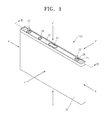
- FIG. 1 a perspective view of a secondary battery 100 according to an embodiment of the present invention
- FIG. 2 is a cross-sectional view taken along a line 11-11 of FIG. 1 .
- the secondary battery 100 includes an electrode assembly 10, electrode terminals 21 and 22, a cap plate 30, a case 34, and short circuit inducing members 50 and 60.
- the secondary battery 100 may be a lithium-ion secondary battery having an angular shape.
- a separator 13 constituting an insulator is disposed between an anode plate 11 and a cathode plate 12, and the anode plate 11, the cathode plate 12, and the separator 13 are wound.
- the electrode assembly 10 is accommodated inside the case 34.
- the electrode terminals 21 and 22 respectively include an anode terminal 21 and a cathode terminal 22.
- the anode terminal 21 and the cathode terminal 22 are respectively electrically connected to the anode plate 11 and the cathode plate 12 of the electrode assembly 10, and are exposed to the outside of the case 34.
- the cap plate 30 is combined with the open side of the case 34.
- the short circuit inducing members 50 and 60 are installed inside the case 34, and are short-circuited according to an external pressure applied to the case 34. In other words, when an external pressure is applied according to a crushing force or a shock, the short circuit inducing members 50 and 60 electrically short-circuit the anode and the cathode.
- the short circuit inducing members 50 and 60 include an anode short circuit inducing member 50 and a cathode short circuit inducing member 60.
- the anode short circuit inducing member 50 is electrically connected to the anode plate 11.
- the cathode short circuit inducing member 60 is electrically connected to the cathode plate 12. When an external pressure is applied, the anode short circuit inducing member 50 and the cathode short circuit inducing member 60 may contact each other to be electrically short-circuited.
- the short circuit inducing members 50 and 60 may be disposed in a space between the electrode assembly 10 and the cap plate 30 in the case 34. Accordingly, when the shape of the case 34 changes due to external pressure, the short circuit inducing members 50 and 60 inside the case 34 induce a short circuit.
- the anode plate 11 and the cathode plate 12 are electrically connected through the short circuit inducing members 50 and 60.
- the short circuit inducing members 50 and 60 may be formed of a material having very low electric resistivity. Accordingly, the short circuit inducing members 50 and 60 barely generate heat during the short circuit, and quickly allow a large current to pass therethrough.
- the short circuit inducing members 50 and 60 prevent the secondary battery 100 from exploding or igniting due to an external shock or a crushing force, and thus stability and reliability of the secondary battery 100 are obtained.
- the case 34 may be pressurized in at least one direction of an X-X', Y-Y', and Z-Z' direction illustrated in FIG. 1 . Accordingly, the short circuit inducing members 50 and 60 may be configured to be short-circuited according to pressure applied in various directions.
- the electrode assembly 10 includes the anode plate 11, the cathode plate 12, and the separator 13.
- the separator 13 constituting an insulator is disposed between the anode plate 11 and the cathode plate 12, and the anode plate 11, the cathode plate 12, and the separator 13 are wound to form the electrode assembly 10.
- the anode plate 11 includes an uncoated portion 11 a and a coated portion 11 b
- the cathode plate 12 includes an uncoated portion 12a and a coated portion 12b.
- the uncoated portions 11 a and 12a are portions on which an active material is not coated on a current collecting body formed of a thin metal foil.
- the coated portion 11 b and 12b are portions on which an active material is coated on the current collecting body.
- the uncoated portion 11 a is formed on one side end of the anode plate 11 along a lengthwise direction of the anode plate 11, and the uncoated portion 12a is formed on one side end of the cathode plate 12 opposite the one side end of the anode plate 11, along a lengthwise direction of the cathode plate 12.
- the electrode assembly 10 may be formed by pressing the anode plate 11, the cathode plate 12, and the separator 13 that are wound to form a cylinder.
- the electrode assembly 10 may be pressed in a plate shape to have a flat portion 18 and a curved portion 19, as shown in FIG. 3 .
- the flat portion 18 may be formed as a circumferential surface of the electrode assembly 10 is flattened by pressing the anode plate 11, the cathode plate 12, and the separator 13 that are wound to form a flat shape.
- the curved portion 19 may be formed as circumferential surfaces of the electrode assembly 10 are curved at each end of the flat portion 18.
- the case 34 may be an angular cap shape having one open side.
- the electrode assembly 10 may be accommodated inside the case 34 with an electrolyte, through the open side of the case 34.
- the cap plate 30 covers the case 34 while the electrode terminals 21 and 22 protrude to the outside of the case 34 through the cap plate 30. A boundary between the case 34 and the cap plate 30 are welded by using a laser, and thus the case 34 accommodating the electrode assembly 10 and the electrolyte is sealed.
- the cap plate 30 may be formed of a thin plate.
- the cap plate 30 may include an electrolyte injecting hole 38a through which the electrolyte is injected.
- a sealing plug 38 may be inserted into the electrolyte injecting hole 38a.
- the cap plate 30 may include a vent member 39 having a groove that may rupture according to internal pressure.
- the cap plate 30 may include terminal holes 21 a and 22a formed by penetrating the cap plate 30.
- the terminal holes 21 a and 22a may respectively include an anode terminal hole 21 a and a cathode terminal hole 22a.
- the anode terminal 21 may protrude to the outside of the case 34 through the anode terminal hole 21 a.
- the cathode terminal 22 may protrude to the outside of the case 34 through the cathode terminal hole 22a.
- Upper and lower gaskets 25 and 27 may be disposed between the cap plate 30 and the electrode terminals 21 and 22 so as to insulate the cap plate 30 and the electrode terminals 21 and 22.
- the electrode terminals 21 and 22 are terms respectively including the anode terminal 21 and the cathode terminal 22.
- the lower gasket 27 is installed in the terminal holes 21 a and 22a by being inserted at the bottom of the cap plate 30, and the upper gasket 25 is installed by being inserted at the top of the cap plate 30.
- a washer 24 is installed on the upper gasket 25 so as to absorb a clamping force.
- a screw thread may be formed on each of the anode terminal 21 and the cathode terminal 22 so as to be fastened with a nut 29. The nut 29 supports the electrode terminals 21 and 22.
- the electrode terminals 21 and 22 may be a rivet type.
- a part of each of the electrode terminals 21 and 22 protrudes to the outside of the case 34 through the terminal holes 21 a and 22a, and the protruding parts of the electrode terminals 21 and 22 may be pressurized to be widely flattened while the upper gasket 25 is inserted between the terminal holes 21 a and 22a and the protruding parts, so as to fix the electrode terminals 21 and 22 to the cap plate 30.
- a current collecting plate 40 may be attached to the uncoated portion 11 a of the electrode assembly 10 by welding.
- the current collecting plate 40 is electrically connected to the anode terminal 21 by using a lead member 28 as a medium. Accordingly, the anode terminal 21 is connected to the anode plate 11 of the electrode assembly 10 through the lead member 28 and the current collecting plate 40.
- the current collecting plate 40 may be attached to the uncoated portion 12a of the electrode assembly 10 by welding.
- the current collecting plate 40 is electrically connected to the cathode terminal 22 by using a lead member 28 as a medium. Accordingly, the cathode terminal 22 is connected to the cathode plate 12 of the electrode assembly 10 through the lead member 28 and the current collecting plate 40.
- the lead member 28 includes a current collecting lead unit 28b attached to the current collecting plate 40, and a terminal lead unit 28a attached to the electrode terminals 21 and 22.
- the anode terminal 21 or the cathode terminal 22 may not include the upper gasket 25, the insulating member 26, and the lower gasket 27 for electrically separating the cap plate 30 and the anode plate 11 or for electrically separating the cap plate 30 and the cathode plate 12.
- the upper gasket 25 and the lower gasket 27 may not be installed between the anode terminal 21 and the cap plate 30, and the insulating member 26 may not be installed between the lead member 28 of the anode terminal 21 and the cap plate 30.
- the anode terminal 21 may contact the cap plate 30 by directly penetrating through the anode terminal holes 21 a without the upper gasket 25 and the lower gasket 27.
- the lead member 28 may directly contact the cap plate 30.
- the cap plate 30 and the case 34 have the same polarity as the anode terminal 21.
- the secondary battery 100 may be a lithium-ion battery, but is not limited thereto. Aside from a lithium-ion battery, the secondary battery 100 may be a nickel-cadmium battery, a nickel-hydrogen battery, or other batteries including a lithium battery.
- the secondary battery 100 may have an angular shape.
- the shape of the secondary battery 100 is not limited thereto, and may have different shapes, such as a cylindrical shape, and a pouch shape.
- the short circuit inducing members 50 and 60 may be electrically connected to the electrode assembly 10 through the lead member 28 and the current collecting plate 40.
- the anode short circuit inducing member 50 may be electrically connected to the anode plate 11 of the electrode assembly 10 through the lead member 28 and the current collecting plate 40.
- the cathode short circuit inducing member 60 may be electrically connected to the cathode plate 12 of the electrode assembly 10 through the lead member 28 and the current collecting plate 40.
- the short circuit inducing members 50 and 60 may be formed to be integrated with the lead member 28.
- the short circuit inducing members 50 and 60 may be separately manufactured, and then may be coupled to the lead member 28 by welding.
- the short circuit inducing members 50 and 60 move together with the lead member 28.
- the anode short circuit inducing member 50 and the cathode short circuit inducing member 60 may contact each other to be electrically short-circuited.
- Pressure by which the short circuit inducing members 50 and 60 are short-circuited may be determined on an experimental basis.
- a distance between the anode short circuit inducing member 50 and the cathode short circuit inducing member 60 may be determined in such a way that a short may be induced according to a predetermined pressure.
- the short circuit inducing members 50 and 60 may be formed of a material having very low electric resistivity.
- the short circuit inducing members 50 and 60 may be formed of a material having low electric resistivity, such as copper (Cu), aluminum (Al) and iron (Fe).
- the short circuit inducing members 50 and 60 may be formed of the same material as the lead member 28.
- the anode plate 11, the current collecting plate 40, and the lead member 28 that are electrically connected to each other may be formed of the same material, for example, Al.
- the anode short circuit inducing member 50 may be formed of the same material as the lead member 28 that are integrated therewith or connected thereto by using welding, for example, Al.
- the cathode plate 12, the current collecting plate 40 and the lead member 28 that are electrically connected to each other may be formed of the same material, for example, Cu.
- the cathode short circuit inducing member 60 may be formed of the same material as the lead member 28 that are integrated therewith or connected thereto by using welding, for example, Cu.
- the short circuit inducing members 50 and 60 are formed of a material having low electric resistivity, the short circuit inducing members 50 and 60 barely generate heat during a short circuit, and quickly let a large current flow. Accordingly, the short circuit inducing members 50 and 60 prevent the secondary battery 100 from exploding or igniting due to an external shock or crushing, thereby obtaining stability and reliability of the secondary battery 100.
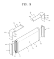
- FIG. 3 is a partial exploded perspective view of the secondary battery 100 of FIG. 1 , wherein a view of a short circuit inducing member is exploded.
- the view of the short circuit inducing members 50 and 60 are exploded with the electrode assembly 10 and the current collecting plate 40.
- the short circuit inducing members 50 and 60 include the anode short circuit inducing member 50 and the cathode short circuit inducing member 60. When external pressure is applied, the anode short circuit inducing member 50 and the cathode short circuit inducing member 60 may contact each other to be electrically short-circuited.
- the short circuit inducing members 50 and 60 include extension portions 51 and 61, and contact portions 52 and 62.
- the extension portions 51 and 61 extend from one end to the other end. One end of each of the extension portions 51 and 61 is fixed or connected to the lead member 28. The other ends of the extension portions 51 and 61 are respectively integrated with or connected to the contact portions 52 and 62.
- the contact portions 52 and 62 contact each other when external pressure is applied to the case 34.
- the extension portions 51 and 61 are stepped from the portion of the lead member 28 contacting the cap plate 30.
- the contact portions 52 and 62 extend preferably perpendicular to the plane in which the extension portions 51 and 61 are formed in. Even more preferably, while the extension portions 51 and 61 extend parallel to and below from the cap plate 30, the contact portions 52 and 62 extend upwards from the extension portions 51 and 61.
- the contact portions 52 and 62 are configured to face each other.
- the anode short circuit inducing member 50 includes the anode extension portion 51 and the anode contact portion 52.
- the anode extension portion 51 extends from one end to the other end.
- One end of the anode extension portion 51 is fixed or connected to the lead member 28 of the anode.
- the other end of anode extension portion 51 is integrated with or connected to the anode contact portion 52.
- the cathode short circuit inducing member 60 includes the cathode extension portion 61 and the cathode contact portion 62.
- the cathode extension portion 61 extends from one end to the other end.
- One end of the cathode extension portion 61 is fixed or connected to the lead member 28 of the cathode.
- the other end of the cathode extension portion 61 is integrated with or connected to the cathode contact portion 62.
- the anode contact portion 52 and the cathode contact portion 62 are spaced apart from each other by a predetermined interval so as to face each other.
- the anode contact portion 52 and the cathode contact portion 62 contact each other when external pressure is applied to the case 34.
- Pressure that induces a short circuit by the short circuit inducing members 50 and 60 may be determined on an experimental basis.
- a distance between the anode contact portion 52 and the cathode contact portion 62 may be determined in such a way that a short circuit is induced according to a predetermined pressure.
- a facing area of the anode contact portion 52 and the cathode contact portion 62 may be greater than an area of a cross section of each of the extension portions 51 and 61. Without the anode contact portion 52 and the cathode contact portion 62, when the anode extension portion 51 and the cathode extension portion 61 are close to each other since external pressure is applied the case 34, the anode extension portion 51 and the cathode extension portion 61 may not correspond to each other, and may not contact each other.
- the secondary battery 100 when external pressure is applied to the case 34, the anode contact portion 52 and the cathode contact portion 62 may easily contact each other.
- the short circuit inducing members 50 and 60 may electrically short-circuit the anode and the cathode easily.
- stability and reliability of the secondary battery 100 are obtained.
- the electrode assembly 10 is pressurized flat to form a plate shape after being wound, and may have an internal space 14 in the center.
- the current collecting plate 40 may include a supporting protrusion 42 that is inserted into the internal space 14, and an attached plate 41 that is welded to the side of the electrode assembly 10 by pressurizing the uncoated portions 11 a and 12a.
- the supporting protrusion 42 extends from a width direction center of the current collecting plate 40 along a lengthwise direction of the current collecting plate 40.
- a height of the supporting protrusion 42 may correspond to a height of the internal space 14 of the electrode assembly 10.
- the supporting protrusion 42 supports the electrode assembly 10 by being inserted into the internal space 14 of the electrode assembly 10. Accordingly, the supporting protrusion 42 may prevent a contact between the electrode assembly 10 and the current collecting plate 40 from being poor due to an external shock.
- the supporting protrusion 42 not only supports the electrode assembly 10 in the lengthwise direction of the internal space 14 but also in a width direction, and thus stably supports the electrode assembly 10.
- An attached plate 41 may be connected to two ends of the supporting protrusion 42.
- the attached plate 41 is disposed contacting the side ends of the electrode assembly 10, and the uncoated portions 11 a and 12a disposed at the side ends of the electrode assembly 10 are pressed.
- the side ends denote a side surface vertical to a central axis when the electrode assembly 10 is wound.
- the attached plate 41 and the uncoated portions 11 a and 12a contact each other over a wide area.
- the attached plate 41 may be attached to the side ends of the electrode assembly 10 by using laser welding. As such, when the laser welding is used, thicknesses of the current collecting plate 40 may be thicker compared to when ultrasonic welding is used, and thus resistance of the current collecting plate 40 may be reduced.
- an overall output of the electrode assembly 10 may be increased by decreasing the areas of the uncoated portions 11 a and 12a and increasing the areas of the coated portions 11 b and 12b.
- stability and reliability of the secondary battery 100 are obtained by preventing an explosion in a pressurized environment according to a crushing force or a shock.
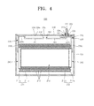
- FIG. 4 is a perspective view of a secondary battery 200 according to another embodiment of the present invention.
- an upper gasket 25, an insulating member 26 and an lower gasket 27 that electrically separate an anode plate 211 or a cathode plate 212 with a cap plate 230 are not installed in any one of an anode terminal and a cathode terminal 222.
- elements of the secondary battery 200 which are identical to the secondary battery 100 of FIG. 1 , have similar reference numerals as the elements of the secondary battery 100, and detailed descriptions thereof are not repeated.
- upper gasket 25 and the lower gasket 27 are not installed in the anode terminal.
- the insulating member 26 is not installed between a lead member 228 of the anode terminal and the cap plate 230.
- the cap plate 230 may be the anode terminal without the upper gasket 25 and the lower gasket 27. Also, the lead member 228 of the anode terminal may directly contact the cap plate 230. In this case, the cap plate 230 and a case 234 have the same polarity as the anode terminal.
- the secondary battery 200 includes an electrode assembly 210; electrode terminals; the cap plate 230; the case 234; and short circuit inducing members 250 and 260.
- a separator 213 constituting an insulator is disposed between the anode plate 211 and the cathode plate 212.
- the case 234 accommodates the electrode assembly 210 therein.
- the electrode terminals may include the anode terminal and the cathode terminal 222.
- the anode terminal and the cathode terminal 222 are respectively electrically connected to the anode plate 211 and the cathode plate 212 of the electrode assembly 210, and are exposed to the outside of the case 234.
- the cap plate 230 is combined with the open side of the case 234.
- the short circuit inducing members 250 and 260 are installed inside the case 234, and are short-circuited according to an external pressure applied to the case 234.
- the short circuit inducing members 250 and 260 include an anode short circuit inducing member 250 and a cathode short circuit inducing member 260.
- the short circuit inducing members 250 and 260 prevent the secondary battery 200 from exploding or igniting due to an external shock or a crushing force, and thus stability and reliability of the secondary battery 200.
- the anode plate 211 includes an anode uncoated portion 211 a and an anode coated portion 211 b.
- the cathode plate 212 includes a cathode uncoated portion 212a and a cathode coated portion 212b.
- the anode terminal may be the cap plate 230.
- the cathode terminal 222 may be formed through a cathode terminal hole 222a to protrude out of the case 234.
- the cap plate 230 may include an electrolyte injecting hole 238a.
- a sealing plug 238 may be inserted into the electrolyte injecting hole 238a.
- a vent member 239 may be installed in the cap plate 230.
- the upper gasket 225 and the lower gasket 227 are disposed between the cap plate 230 and the cathode terminal 222 so as to insulate the cap plate 230 and the cathode terminal 222 from each other.
- a washer 224 is installed on the upper gasket 225 so as to absorb a clamping force.
- the cathode terminal 222 may include a nut 229. Alternatively, the cathode terminal 222 may be a rivet type.
- a current collector plate 240 may be attached to the cathode uncoated portion 212a of the electrode assembly 210 by using welding.
- the current collector plate 240 is electrically connected to the cathode terminal 222 by using the lead member 228 as a medium.
- the insulating member 226 for insulation is installed between the lead member 228 and the cap plate 230.
- the lead member 228 includes a current collector lead portion 228b attached to the current collector plate 240, and a terminal lead portion 228a attached to the cathode terminal 222 or the cap plate 230.
- the short circuit inducing members 250 and 260 include extension portions 251 and 261, and contact portions 252 and 262.
- the anode short circuit inducing member 250 includes an anode extension portion 251 and a cathode contact portion 252.
- the cathode short circuit inducing member 260 includes a cathode extension portion 261 and a cathode contact portion 262.
- the current collector plate 240 may include a supporting protrusion and an attached plate.
- the supporting protrusion is inserted into an internal space 214 of the electrode assembly 210 so as to support the electrode assembly 210.
- the attached plate may be connected to two side ends of the supporting protrusion.
- FIG. 5 is a cross-sectional view of a secondary battery 300 according to another embodiment of the present invention.
- the anode short circuit inducing member 250 is formed by the lead member 328 itself, and a short circuit inducing member 360 replaces the cathode short circuit inducing member 260.
- elements of the secondary battery 300 which are identical to the secondary battery 200 of FIG. 4 , have same reference numerals as the elements of the secondary battery 200, and detailed descriptions thereof are not repeated.
- the short circuit inducing member 360 may contact a lead member 328 being the anode short circuit inducing member to induce a short circuit according to external pressure applied to the case 234.
- the short circuit inducing member 360 may contact the cap plate 230 or the case 234 to induce a short circuit according to external pressure applied to the case 234.
- the anode short circuit inducing member 250 of Fig. 4 is formed by the cap plate 230 or the case 234 and no additional element needs to be provided.
- the cap plate 230 and/or the case 234 are electrically connected to the anode plate 211 and the cathode plate 212 of the electrode assembly 210 through a lead member 328, and function as an anode terminal or a cathode terminal, respectively, which are exposed to the outside of the case 234.
- the short circuit inducing member 360 may be electrically connected to the cathode plate 212 or the anode plate 211 of the electrode assembly 210 through the lead member 228.
- the short circuit inducing member 360 may contact the lead member 328 to induce a short circuit.
- the short circuit inducing member 360 prevents an explosion of the secondary battery 300 in a pressurized environment according to a crushing force or a shock, thereby obtaining stability and reliability of the secondary battery 300.
- the short circuit inducing member 360 includes an extension portion 361 and a contact portion 362.
- the extension portion 361 extends from a first end to a second end.
- the first end of the extension portion 361 may be fixed or connected to the lead member 228, and the second end of the extension portion 361 may be integrally formed with the contact portion 362 or may be connected to the contact portion 362.
- the extension portion 361 is formed parallel to the cap plate 230 while the contact portion 362 is formed perpendicular to the cap plate.
- the contact portion 362 extends upward from the extension portion 361 and perpendicular to the extension portion 361.
- the contact portion 362 faces a part of the lead member 328.
- the contact portion 362 may contact the lead member 328 when pressure is applied to the case 234.
- the contact portion 362 is bent towards the cap plate 230 from the extension portion 361.
- a short circuit may be easily induced.
- the short circuit inducing member 360 contacts the lead member 328, a short circuit between the anode plate 211 and the cathode plate 212 is induced.
- Pressure by which a short circuit is induced by the short circuit inducing member 360 may be determined on an experimental basis.
- a distance between the contact portion 362 and the lead member 328 or the cap plate 230 and/or the case 234 may be determined in such way that a short circuit may be induced according to a predetermined pressure.
- stability and reliability of a secondary battery are obtained by preventing explosion in a pressurized environment due to a crushing force or a shock.
Landscapes
- Chemical & Material Sciences (AREA)
- Chemical Kinetics & Catalysis (AREA)
- Electrochemistry (AREA)
- General Chemical & Material Sciences (AREA)
- Engineering & Computer Science (AREA)
- Manufacturing & Machinery (AREA)
- Connection Of Batteries Or Terminals (AREA)
Abstract
Description
- One or more embodiments of the present invention relate to a secondary battery, and more particularly, to a secondary battery that does not explode even when crushed or experiencing a shock.
- Secondary batteries are rechargeable batteries that can be charged and discharged, unlike primary batteries that cannot be charged. Secondary batteries are widely used in high-technology electronic devices, such as cellular phones, laptops, and camcorders, and are also used for cars.
- Secondary batteries include an electrode assembly and an electrolyte. The electrode assembly includes a positive plate, a negative plate, and a separator. The electrolyte mostly includes a lithium ion. The positive plate and the negative plate of the electrode assembly may each include an electrode tap protruding to outside the electrode assembly.
- The electrode assembly is accommodated inside a case, and an electrode terminal may be exposed outside the case. The electrode tap that protrudes outside of the electrode assembly may be electrically connected to the electrode terminal. The case may have a cylindrical shape or an angular shape.
- Secondary batteries may be used in harsh environments, such as an environment that may cause crushing or a shock. Accordingly, stability and reliability of secondary batteries must be high even in such harsh environments.
- One or more embodiments of the present invention include a secondary battery that has high stability and reliability by preventing explosion in a pressurized environment due to a crushing force or a shock.
- According to one or more embodiments of the present invention, a rechargeable battery is provided, comprising an electrode assembly having a first electrode, a second electrode, and a separator located between the first and second electrode and a case for mounting the electrode assembly therein. Further provided is a first short circuit inducing member located inside the case and being electrically coupled to the first electrode of the electrode assembly, and a second short circuit inducing member located inside the case and being electrically coupled to the second electrode of the electrode assembly, wherein the first and second short circuit inducing members are spaced from each other.
- The first and second short circuit inducing members are preferably configured to contact each other to induce a short circuit between the first and second electrode upon a deformation of the case.
- Thus, the rechargeable battery can be prevented from explosion in response to an external force or shock.
- The distance between the first and second short circuit inducing member is preferably configured to induce a short circuit according to a predetermined force exertion on the case. In other words, the distance is formed such that an external force having a magnitude which may cause explosion of a rechargeable battery of the state of the art is bridged to establish a short between the first and second short circuit inducing members.
- In one embodiment, the rechargeable battery may further comprise a cap plate for covering an opening of the case, wherein at least one of the first or second short circuit inducing members is disposed in a space between the electrode assembly and the cap plate.
- The at least one of the first or second short circuit inducing members may be electrically coupled to the respective first or second electrode via a lead member.
- Preferably, the at least one of the first or second short circuit inducing member is formed integrally with the respective lead member.
- In one embodiment, the at least one of the first or second short circuit inducing member is identical with the respective lead member.
- In another embodiment, the at least one of the first or second short circuit inducing member is welded to the respective lead member.
- The first or second short circuit inducing members is preferably formed of the same material as the respective lead member.
- In one embodiment, the first electrode and the first short circuit inducing member are formed of the same material, and the second electrode and the second short circuit inducing member are formed of the same material.
- The first electrode may be an anode and the first electrode and the first short circuit inducing member may be formed of aluminum. The second electrode may be a cathode and the second electrode and the second short circuit inducing member may be formed of copper.
- Preferably, at least one of the first or second short circuit inducing members comprises an extension portion and a contact portion, the contact portion being adapted to establish a contact between the first and second short circuit inducing members.
- The first short circuit inducing member may comprise a first extension portion and a first contact portion and the second short circuit inducing member may comprise a second extension portion and a second contact portion, the first and second contact portions being adapted to contact each other. Preferably, one end of an extension portion is coupled to the respective first or second electrode and the other end is coupled to the respective contact portion. A facing area of a contact portion is preferably greater than the area of a cross section of its corresponding extension portion.
- The cap plate may be electrically coupled to the first or second electrode via a lead member.
- According to one or more embodiments of the present invention, a secondary battery may have high stability and reliability by preventing explosion in a pressurized environment due to a crushing force or a shock.
-
-
FIG. 1 a perspective view of a secondary battery according to an embodiment of the present invention; -
FIG. 2 is a cross-sectional view taken along a line II-II ofFIG. 1 ; -
FIG. 3 is a partial exploded perspective view of the secondary battery ofFIG. 1 , wherein a view of a short circuit inducing member is exploded; -
FIG. 4 is a cross-sectional view of a secondary battery according to another embodiment of the present invention; and -
FIG. 5 is a cross-sectional view of a secondary battery according to another embodiment of the present invention. - Reference will now be made in detail to embodiments, examples of which are illustrated in the accompanying drawings
-
FIG. 1 a perspective view of asecondary battery 100 according to an embodiment of the present invention, andFIG. 2 is a cross-sectional view taken along a line 11-11 ofFIG. 1 . - Referring to
FIGS. 1 and2 , thesecondary battery 100 includes anelectrode assembly 10,electrode terminals cap plate 30, acase 34, and shortcircuit inducing members secondary battery 100 may be a lithium-ion secondary battery having an angular shape. - In the
electrode assembly 10, aseparator 13 constituting an insulator is disposed between ananode plate 11 and acathode plate 12, and theanode plate 11, thecathode plate 12, and theseparator 13 are wound. Theelectrode assembly 10 is accommodated inside thecase 34. Theelectrode terminals anode terminal 21 and acathode terminal 22. Theanode terminal 21 and thecathode terminal 22 are respectively electrically connected to theanode plate 11 and thecathode plate 12 of theelectrode assembly 10, and are exposed to the outside of thecase 34. Thecap plate 30 is combined with the open side of thecase 34. - The short
circuit inducing members case 34, and are short-circuited according to an external pressure applied to thecase 34. In other words, when an external pressure is applied according to a crushing force or a shock, the shortcircuit inducing members - The short
circuit inducing members circuit inducing member 50 and a cathode shortcircuit inducing member 60. The anode shortcircuit inducing member 50 is electrically connected to theanode plate 11. The cathode shortcircuit inducing member 60 is electrically connected to thecathode plate 12. When an external pressure is applied, the anode shortcircuit inducing member 50 and the cathode shortcircuit inducing member 60 may contact each other to be electrically short-circuited. - The short
circuit inducing members electrode assembly 10 and thecap plate 30 in thecase 34. Accordingly, when the shape of thecase 34 changes due to external pressure, the shortcircuit inducing members case 34 induce a short circuit. - During the short circuit, the
anode plate 11 and thecathode plate 12 are electrically connected through the shortcircuit inducing members circuit inducing members circuit inducing members - Accordingly, the short
circuit inducing members secondary battery 100 from exploding or igniting due to an external shock or a crushing force, and thus stability and reliability of thesecondary battery 100 are obtained. - Meanwhile, during crushing or a shock, the
case 34 may be pressurized in at least one direction of an X-X', Y-Y', and Z-Z' direction illustrated inFIG. 1 . Accordingly, the shortcircuit inducing members - The
electrode assembly 10 includes theanode plate 11, thecathode plate 12, and theseparator 13. Here, theseparator 13 constituting an insulator is disposed between theanode plate 11 and thecathode plate 12, and theanode plate 11, thecathode plate 12, and theseparator 13 are wound to form theelectrode assembly 10. - The
anode plate 11 includes anuncoated portion 11 a and acoated portion 11 b, and thecathode plate 12 includes anuncoated portion 12a and acoated portion 12b. Theuncoated portions coated portion - The
uncoated portion 11 a is formed on one side end of theanode plate 11 along a lengthwise direction of theanode plate 11, and theuncoated portion 12a is formed on one side end of thecathode plate 12 opposite the one side end of theanode plate 11, along a lengthwise direction of thecathode plate 12. - Meanwhile, the
electrode assembly 10 may be formed by pressing theanode plate 11, thecathode plate 12, and theseparator 13 that are wound to form a cylinder. Here, theelectrode assembly 10 may be pressed in a plate shape to have aflat portion 18 and acurved portion 19, as shown inFIG. 3 . - The
flat portion 18 may be formed as a circumferential surface of theelectrode assembly 10 is flattened by pressing theanode plate 11, thecathode plate 12, and theseparator 13 that are wound to form a flat shape. Thecurved portion 19 may be formed as circumferential surfaces of theelectrode assembly 10 are curved at each end of theflat portion 18. - The
case 34 may be an angular cap shape having one open side. Theelectrode assembly 10 may be accommodated inside thecase 34 with an electrolyte, through the open side of thecase 34. Thecap plate 30 covers thecase 34 while theelectrode terminals case 34 through thecap plate 30. A boundary between thecase 34 and thecap plate 30 are welded by using a laser, and thus thecase 34 accommodating theelectrode assembly 10 and the electrolyte is sealed. - The
cap plate 30 may be formed of a thin plate. Thecap plate 30 may include anelectrolyte injecting hole 38a through which the electrolyte is injected. A sealingplug 38 may be inserted into theelectrolyte injecting hole 38a. Also, thecap plate 30 may include avent member 39 having a groove that may rupture according to internal pressure. - The
cap plate 30 may includeterminal holes cap plate 30. The terminal holes 21 a and 22a may respectively include ananode terminal hole 21 a and acathode terminal hole 22a. Theanode terminal 21 may protrude to the outside of thecase 34 through theanode terminal hole 21 a. Thecathode terminal 22 may protrude to the outside of thecase 34 through thecathode terminal hole 22a. - Upper and
lower gaskets cap plate 30 and theelectrode terminals cap plate 30 and theelectrode terminals electrode terminals anode terminal 21 and thecathode terminal 22. - The
lower gasket 27 is installed in the terminal holes 21 a and 22a by being inserted at the bottom of thecap plate 30, and theupper gasket 25 is installed by being inserted at the top of thecap plate 30. Awasher 24 is installed on theupper gasket 25 so as to absorb a clamping force. A screw thread may be formed on each of theanode terminal 21 and thecathode terminal 22 so as to be fastened with anut 29. Thenut 29 supports theelectrode terminals - Alternatively, the
electrode terminals electrode terminals case 34 through the terminal holes 21 a and 22a, and the protruding parts of theelectrode terminals upper gasket 25 is inserted between theterminal holes electrode terminals cap plate 30. - A
current collecting plate 40 may be attached to theuncoated portion 11 a of theelectrode assembly 10 by welding. Thecurrent collecting plate 40 is electrically connected to theanode terminal 21 by using alead member 28 as a medium. Accordingly, theanode terminal 21 is connected to theanode plate 11 of theelectrode assembly 10 through thelead member 28 and thecurrent collecting plate 40. - Also, the
current collecting plate 40 may be attached to theuncoated portion 12a of theelectrode assembly 10 by welding. Thecurrent collecting plate 40 is electrically connected to thecathode terminal 22 by using alead member 28 as a medium. Accordingly, thecathode terminal 22 is connected to thecathode plate 12 of theelectrode assembly 10 through thelead member 28 and thecurrent collecting plate 40. - An insulating
member 26 for insulation is installed between thelead member 28 and thecap plate 30. Thelead member 28 includes a current collectinglead unit 28b attached to thecurrent collecting plate 40, and aterminal lead unit 28a attached to theelectrode terminals - According to another embodiment of the present invention, the
anode terminal 21 or thecathode terminal 22 may not include theupper gasket 25, the insulatingmember 26, and thelower gasket 27 for electrically separating thecap plate 30 and theanode plate 11 or for electrically separating thecap plate 30 and thecathode plate 12. - For example, the
upper gasket 25 and thelower gasket 27 may not be installed between theanode terminal 21 and thecap plate 30, and the insulatingmember 26 may not be installed between thelead member 28 of theanode terminal 21 and thecap plate 30. - Here, the
anode terminal 21 may contact thecap plate 30 by directly penetrating through the anode terminal holes 21 a without theupper gasket 25 and thelower gasket 27. Also, thelead member 28 may directly contact thecap plate 30. In this case, thecap plate 30 and thecase 34 have the same polarity as theanode terminal 21. - The
secondary battery 100 according to the current embodiment of the present invention may be a lithium-ion battery, but is not limited thereto. Aside from a lithium-ion battery, thesecondary battery 100 may be a nickel-cadmium battery, a nickel-hydrogen battery, or other batteries including a lithium battery. - As shown in
FIG. 1 , thesecondary battery 100 may have an angular shape. However, the shape of thesecondary battery 100 is not limited thereto, and may have different shapes, such as a cylindrical shape, and a pouch shape. - The short
circuit inducing members electrode assembly 10 through thelead member 28 and thecurrent collecting plate 40. In other words, the anode shortcircuit inducing member 50 may be electrically connected to theanode plate 11 of theelectrode assembly 10 through thelead member 28 and thecurrent collecting plate 40. The cathode shortcircuit inducing member 60 may be electrically connected to thecathode plate 12 of theelectrode assembly 10 through thelead member 28 and thecurrent collecting plate 40. - In addition, the short
circuit inducing members lead member 28. Alternatively, the shortcircuit inducing members lead member 28 by welding. - When external pressure is applied to the
case 34, the shortcircuit inducing members lead member 28. In this case, the anode shortcircuit inducing member 50 and the cathode shortcircuit inducing member 60 may contact each other to be electrically short-circuited. - Pressure by which the short
circuit inducing members circuit inducing member 50 and the cathode shortcircuit inducing member 60 may be determined in such a way that a short may be induced according to a predetermined pressure. - The short
circuit inducing members circuit inducing members circuit inducing members lead member 28. - The
anode plate 11, thecurrent collecting plate 40, and thelead member 28 that are electrically connected to each other may be formed of the same material, for example, Al. In this case, the anode shortcircuit inducing member 50 may be formed of the same material as thelead member 28 that are integrated therewith or connected thereto by using welding, for example, Al. - The
cathode plate 12, thecurrent collecting plate 40 and thelead member 28 that are electrically connected to each other may be formed of the same material, for example, Cu. Here, the cathode shortcircuit inducing member 60 may be formed of the same material as thelead member 28 that are integrated therewith or connected thereto by using welding, for example, Cu. - As such, since the short
circuit inducing members circuit inducing members circuit inducing members secondary battery 100 from exploding or igniting due to an external shock or crushing, thereby obtaining stability and reliability of thesecondary battery 100. -
FIG. 3 is a partial exploded perspective view of thesecondary battery 100 ofFIG. 1 , wherein a view of a short circuit inducing member is exploded. InFIG. 3 , the view of the shortcircuit inducing members electrode assembly 10 and thecurrent collecting plate 40. - The short
circuit inducing members circuit inducing member 50 and the cathode shortcircuit inducing member 60. When external pressure is applied, the anode shortcircuit inducing member 50 and the cathode shortcircuit inducing member 60 may contact each other to be electrically short-circuited. - The short
circuit inducing members extension portions contact portions extension portions extension portions lead member 28. The other ends of theextension portions contact portions contact portions case 34. Preferably, theextension portions lead member 28 contacting thecap plate 30. Thecontact portions extension portions extension portions cap plate 30, thecontact portions extension portions contact portions - The anode short
circuit inducing member 50 includes theanode extension portion 51 and theanode contact portion 52. Theanode extension portion 51 extends from one end to the other end. One end of theanode extension portion 51 is fixed or connected to thelead member 28 of the anode. The other end ofanode extension portion 51 is integrated with or connected to theanode contact portion 52. - The cathode short
circuit inducing member 60 includes thecathode extension portion 61 and thecathode contact portion 62. Thecathode extension portion 61 extends from one end to the other end. One end of thecathode extension portion 61 is fixed or connected to thelead member 28 of the cathode. The other end of thecathode extension portion 61 is integrated with or connected to thecathode contact portion 62. - The
anode contact portion 52 and thecathode contact portion 62 are spaced apart from each other by a predetermined interval so as to face each other. Theanode contact portion 52 and thecathode contact portion 62 contact each other when external pressure is applied to thecase 34. - Pressure that induces a short circuit by the short
circuit inducing members anode contact portion 52 and thecathode contact portion 62 may be determined in such a way that a short circuit is induced according to a predetermined pressure. - To achieve this, a facing area of the
anode contact portion 52 and thecathode contact portion 62 may be greater than an area of a cross section of each of theextension portions anode contact portion 52 and thecathode contact portion 62, when theanode extension portion 51 and thecathode extension portion 61 are close to each other since external pressure is applied thecase 34, theanode extension portion 51 and thecathode extension portion 61 may not correspond to each other, and may not contact each other. - However, in the
secondary battery 100 according to the present embodiment, when external pressure is applied to thecase 34, theanode contact portion 52 and thecathode contact portion 62 may easily contact each other. Thus, when an external pressure is applied to thecase 34 according to a crushing force or a shock, the shortcircuit inducing members secondary battery 100 are obtained. - The
electrode assembly 10 is pressurized flat to form a plate shape after being wound, and may have aninternal space 14 in the center. Thecurrent collecting plate 40 may include a supportingprotrusion 42 that is inserted into theinternal space 14, and an attachedplate 41 that is welded to the side of theelectrode assembly 10 by pressurizing theuncoated portions - The supporting
protrusion 42 extends from a width direction center of thecurrent collecting plate 40 along a lengthwise direction of thecurrent collecting plate 40. A height of the supportingprotrusion 42 may correspond to a height of theinternal space 14 of theelectrode assembly 10. - The supporting
protrusion 42 supports theelectrode assembly 10 by being inserted into theinternal space 14 of theelectrode assembly 10. Accordingly, the supportingprotrusion 42 may prevent a contact between theelectrode assembly 10 and thecurrent collecting plate 40 from being poor due to an external shock. The supportingprotrusion 42 not only supports theelectrode assembly 10 in the lengthwise direction of theinternal space 14 but also in a width direction, and thus stably supports theelectrode assembly 10. - An attached
plate 41 may be connected to two ends of the supportingprotrusion 42. The attachedplate 41 is disposed contacting the side ends of theelectrode assembly 10, and theuncoated portions electrode assembly 10 are pressed. Here, the side ends denote a side surface vertical to a central axis when theelectrode assembly 10 is wound. - Accordingly, the attached
plate 41 and theuncoated portions plate 41 may be attached to the side ends of theelectrode assembly 10 by using laser welding. As such, when the laser welding is used, thicknesses of thecurrent collecting plate 40 may be thicker compared to when ultrasonic welding is used, and thus resistance of thecurrent collecting plate 40 may be reduced. - Also, since the
current collecting plate 40 is fixed to the sides of theuncoated portions electrode assembly 10 may be increased by decreasing the areas of theuncoated portions coated portions - According to the current embodiment of the present invention, stability and reliability of the
secondary battery 100 are obtained by preventing an explosion in a pressurized environment according to a crushing force or a shock. -
FIG. 4 is a perspective view of asecondary battery 200 according to another embodiment of the present invention. Compared to thesecondary battery 100 ofFIG. 1 , in thesecondary battery 200 according to the current embodiment of the present invention, anupper gasket 25, an insulatingmember 26 and anlower gasket 27 that electrically separate ananode plate 211 or acathode plate 212 with acap plate 230 are not installed in any one of an anode terminal and acathode terminal 222. - In
FIG. 4 , elements of thesecondary battery 200, which are identical to thesecondary battery 100 ofFIG. 1 , have similar reference numerals as the elements of thesecondary battery 100, and detailed descriptions thereof are not repeated. - Referring to
FIG. 4 , in thesecondary battery 200,upper gasket 25 and thelower gasket 27 are not installed in the anode terminal. The insulatingmember 26 is not installed between alead member 228 of the anode terminal and thecap plate 230. - In this case, the
cap plate 230 may be the anode terminal without theupper gasket 25 and thelower gasket 27. Also, thelead member 228 of the anode terminal may directly contact thecap plate 230. In this case, thecap plate 230 and acase 234 have the same polarity as the anode terminal. - The
secondary battery 200 includes anelectrode assembly 210; electrode terminals; thecap plate 230; thecase 234; and short circuit inducing members 250 and 260. - In the
electrode assembly 210, aseparator 213 constituting an insulator is disposed between theanode plate 211 and thecathode plate 212. Thecase 234 accommodates theelectrode assembly 210 therein. The electrode terminals may include the anode terminal and thecathode terminal 222. - The anode terminal and the
cathode terminal 222 are respectively electrically connected to theanode plate 211 and thecathode plate 212 of theelectrode assembly 210, and are exposed to the outside of thecase 234. Thecap plate 230 is combined with the open side of thecase 234. - The short circuit inducing members 250 and 260 are installed inside the
case 234, and are short-circuited according to an external pressure applied to thecase 234. The short circuit inducing members 250 and 260 include an anode short circuit inducing member 250 and a cathode short circuit inducing member 260. - The short circuit inducing members 250 and 260 prevent the
secondary battery 200 from exploding or igniting due to an external shock or a crushing force, and thus stability and reliability of thesecondary battery 200. - The
anode plate 211 includes an anodeuncoated portion 211 a and an anode coatedportion 211 b. Thecathode plate 212 includes a cathodeuncoated portion 212a and a cathode coatedportion 212b. The anode terminal may be thecap plate 230. Thecathode terminal 222 may be formed through acathode terminal hole 222a to protrude out of thecase 234. - The
cap plate 230 may include anelectrolyte injecting hole 238a. A sealingplug 238 may be inserted into theelectrolyte injecting hole 238a. Avent member 239 may be installed in thecap plate 230. Theupper gasket 225 and thelower gasket 227 are disposed between thecap plate 230 and thecathode terminal 222 so as to insulate thecap plate 230 and thecathode terminal 222 from each other. Awasher 224 is installed on theupper gasket 225 so as to absorb a clamping force. Thecathode terminal 222 may include anut 229. Alternatively, thecathode terminal 222 may be a rivet type. - A
current collector plate 240 may be attached to the cathodeuncoated portion 212a of theelectrode assembly 210 by using welding. Thecurrent collector plate 240 is electrically connected to thecathode terminal 222 by using thelead member 228 as a medium. The insulatingmember 226 for insulation is installed between thelead member 228 and thecap plate 230. Thelead member 228 includes a currentcollector lead portion 228b attached to thecurrent collector plate 240, and aterminal lead portion 228a attached to thecathode terminal 222 or thecap plate 230. - The short circuit inducing members 250 and 260 include
extension portions contact portions anode extension portion 251 and acathode contact portion 252. The cathode short circuit inducing member 260 includes acathode extension portion 261 and acathode contact portion 262. - The
current collector plate 240 may include a supporting protrusion and an attached plate. The supporting protrusion is inserted into an internal space 214 of theelectrode assembly 210 so as to support theelectrode assembly 210. The attached plate may be connected to two side ends of the supporting protrusion. -
FIG. 5 is a cross-sectional view of asecondary battery 300 according to another embodiment of the present invention. Compared to thesecondary battery 200 ofFIG. 4 , in thesecondary battery 300 according to the current embodiment of the present invention, the anode short circuit inducing member 250 is formed by thelead member 328 itself, and a shortcircuit inducing member 360 replaces the cathode short circuit inducing member 260. - In
FIG. 5 , elements of thesecondary battery 300, which are identical to thesecondary battery 200 ofFIG. 4 , have same reference numerals as the elements of thesecondary battery 200, and detailed descriptions thereof are not repeated. - Referring to
FIG. 5 , in thesecondary battery 300, the shortcircuit inducing member 360 may contact alead member 328 being the anode short circuit inducing member to induce a short circuit according to external pressure applied to thecase 234. But, this invention is not limited thereto, the shortcircuit inducing member 360 may contact thecap plate 230 or thecase 234 to induce a short circuit according to external pressure applied to thecase 234. In this case, the anode short circuit inducing member 250 ofFig. 4 is formed by thecap plate 230 or thecase 234 and no additional element needs to be provided. - In this case, the
cap plate 230 and/or thecase 234 are electrically connected to theanode plate 211 and thecathode plate 212 of theelectrode assembly 210 through alead member 328, and function as an anode terminal or a cathode terminal, respectively, which are exposed to the outside of thecase 234. In addition, the shortcircuit inducing member 360 may be electrically connected to thecathode plate 212 or theanode plate 211 of theelectrode assembly 210 through thelead member 228. - In this case, when a predetermined pressure or more is applied to the
case 234, the shortcircuit inducing member 360 may contact thelead member 328 to induce a short circuit. Thus, the shortcircuit inducing member 360 prevents an explosion of thesecondary battery 300 in a pressurized environment according to a crushing force or a shock, thereby obtaining stability and reliability of thesecondary battery 300. - The short
circuit inducing member 360 includes anextension portion 361 and acontact portion 362. Theextension portion 361 extends from a first end to a second end. The first end of theextension portion 361 may be fixed or connected to thelead member 228, and the second end of theextension portion 361 may be integrally formed with thecontact portion 362 or may be connected to thecontact portion 362. In the embodiment shown inFig. 5 , theextension portion 361 is formed parallel to thecap plate 230 while thecontact portion 362 is formed perpendicular to the cap plate. Specifically, thecontact portion 362 extends upward from theextension portion 361 and perpendicular to theextension portion 361. Thecontact portion 362 faces a part of thelead member 328. - The
contact portion 362 may contact thelead member 328 when pressure is applied to thecase 234. Thecontact portion 362 is bent towards thecap plate 230 from theextension portion 361. Thus, when pressure is applied to thecase 234, a short circuit may be easily induced. In this case, when the shortcircuit inducing member 360 contacts thelead member 328, a short circuit between theanode plate 211 and thecathode plate 212 is induced. - Pressure by which a short circuit is induced by the short
circuit inducing member 360 may be determined on an experimental basis. In this case, a distance between thecontact portion 362 and thelead member 328 or thecap plate 230 and/or thecase 234 may be determined in such way that a short circuit may be induced according to a predetermined pressure. - As described above, according to the one or more of the above embodiments of the present invention, stability and reliability of a secondary battery are obtained by preventing explosion in a pressurized environment due to a crushing force or a shock.
- It should be understood that the exemplary embodiments described herein should be considered in a descriptive sense only and not for purposes of limitation. Descriptions of features or aspects within each embodiment should typically be considered as available for other similar features or aspects in other embodiments.
Claims (15)
- A rechargeable battery (100, 200) comprising:an electrode assembly (10) comprising a first electrode (11), a second electrode (12), and a separator (13) located between the first and second electrode (11, 12);a case (34) for mounting the electrode assembly (10) therein;,characterized in thata first short circuit inducing member (50) is provided inside the case (34) and electrically coupled to the first electrode (11) of the electrode assembly (10), anda second short circuit inducing member (60) is provided inside the case (34) and electrically coupled to the second electrode (12) of the electrode assembly (10),wherein the first and second short circuit inducing members (50, 60) are spaced from each other.
- Rechargeable battery (100, 200) of claim 1, wherein the first and second short circuit inducing members (50, 60) are configured to contact each other to induce a short circuit between the first and second electrode (11, 12) upon a deformation of the case (34).
- Rechargeable battery (100, 200) of claim 1 or 2, wherein the distance between the first and second short circuit inducing members (50, 60) is configured to induce a short circuit according to a predetermined force exertion on the case (34).
- Rechargeable battery (100, 200) of any of the previous claims, further comprising a cap plate (30) for covering an opening of the case (34), wherein at least one of the first or second short circuit inducing members (50, 60) is disposed in a space between the electrode assembly (10) and the cap plate (30).
- Rechargeable battery (100, 200) of any of the previous claims, wherein at least one of the first or second short circuit inducing members (50, 60) is electrically coupled to the respective first or second electrode (11, 12) via a lead member (28).
- Rechargeable battery (100, 200) of claim 5, wherein the at least one of the first or second short circuit inducing members (50, 60) is formed integrally with the respective lead member (28) or identical with the respective lead member (28).
- Rechargeable battery (100, 200) of claim 5, wherein the at least one of the first or second short circuit inducing members (50, 60) is welded to the respective lead member (28).
- Rechargeable battery (100, 200) of any of claims 5 to 7, wherein the first or second short circuit inducing members (50, 60) are formed of the same material as their respective lead members (28).
- Rechargeable battery (100, 200) of any of the previous claims, wherein the first electrode (11) and the first short circuit inducing member (50) are formed of the same material, and the second electrode (12) and the second short circuit inducing member (60) are formed of the same material.
- Rechargeable battery (100, 200) of any of the previous claims, wherein the first electrode (11) is an anode and the first electrode (11) and the first short circuit inducing member (50) are formed of aluminum, and the second electrode (12) is a cathode and the second electrode (12) and the second short circuit inducing member (60) are formed of copper.
- Rechargeable battery (100, 200) of any of the previous claims 1 to 10, wherein at least one of the first or second short circuit inducing members (50, 60) comprises an extension portion (51, 61) and a contact portion (52, 62), the contact portion (52, 62) being adapted to establish a contact between the first and second short circuit inducing members (50, 60).
- Rechargeable battery (100, 200) of claim 11, wherein the first short circuit inducing member (50) comprises a first extension portion (51) and a first contact portion (52) and the second short circuit inducing member (60) comprises a second extension portion (61) and a second contact portion (62), the first and second contact portions (52, 62) being adapted to contact each other..
- Rechargeable battery (100, 200) of claim 11 or 12, wherein one end of an extension portion (51, 61) is coupled to the respective first or second electrode (11, 12) and the other end is coupled to the respective contact portion (52, 62).
- Rechargeable battery (100, 200) of claim 11 to 13, wherein a facing area of a contact portion (52, 62) is greater than the area of a cross section of its corresponding extension portion (51, 61).
- Rechargeable battery (200) of claim 4, wherein the cap plate (230) is electrically coupled to the first or second electrode (211, 212) via a lead member (228).
Applications Claiming Priority (1)
| Application Number | Priority Date | Filing Date | Title |
|---|---|---|---|
| US30588810P | 2010-02-18 | 2010-02-18 |
Publications (2)
| Publication Number | Publication Date |
|---|---|
| EP2362466A1 true EP2362466A1 (en) | 2011-08-31 |
| EP2362466B1 EP2362466B1 (en) | 2014-04-16 |
Family
ID=42787338
Family Applications (1)
| Application Number | Title | Priority Date | Filing Date |
|---|---|---|---|
| EP10168818.2A Active EP2362466B1 (en) | 2010-02-18 | 2010-07-08 | Rechargeable battery with short circuit inducing members |
Country Status (5)
| Country | Link |
|---|---|
| US (1) | US8691424B2 (en) |
| EP (1) | EP2362466B1 (en) |
| JP (1) | JP5539910B2 (en) |
| KR (1) | KR101217071B1 (en) |
| CN (1) | CN102163708B (en) |
Cited By (2)
| Publication number | Priority date | Publication date | Assignee | Title |
|---|---|---|---|---|
| EP3321993A1 (en) * | 2016-11-15 | 2018-05-16 | Contemporary Amperex Technology Co., Limited | Secondary battery |
| EP3627589A1 (en) * | 2018-09-18 | 2020-03-25 | Contemporary Amperex Technology Co., Limited | Secondary battery |
Families Citing this family (19)
| Publication number | Priority date | Publication date | Assignee | Title |
|---|---|---|---|---|
| KR101222267B1 (en) * | 2010-12-09 | 2013-01-15 | 로베르트 보쉬 게엠베하 | Secondary battery |
| JP5958712B2 (en) * | 2011-08-31 | 2016-08-02 | パナソニックIpマネジメント株式会社 | Square battery |
| JP5582128B2 (en) * | 2011-11-04 | 2014-09-03 | トヨタ自動車株式会社 | Secondary battery |
| KR101715954B1 (en) * | 2011-11-07 | 2017-03-14 | 삼성에스디아이 주식회사 | Secondary battery |
| KR101715955B1 (en) | 2011-11-09 | 2017-03-28 | 삼성에스디아이 주식회사 | Secondary bttery |
| KR101925584B1 (en) * | 2011-11-30 | 2018-12-06 | 삼성에스디아이 주식회사 | Rechargeable battery |
| DE102011089088A1 (en) * | 2011-12-19 | 2013-06-20 | Robert Bosch Gmbh | Electric energy storage cell and method for producing an electrical energy storage cell |
| CN202905820U (en) * | 2012-10-19 | 2013-04-24 | 宁德时代新能源科技有限公司 | Lithium ion battery adopting safety protection bracket |
| KR101711983B1 (en) * | 2013-09-16 | 2017-03-08 | 삼성에스디아이 주식회사 | Rechargeable battery |
| KR102210891B1 (en) * | 2014-02-20 | 2021-02-02 | 삼성에스디아이 주식회사 | Secondary battery |
| JP6639111B2 (en) * | 2015-06-05 | 2020-02-05 | 株式会社東芝 | Rechargeable battery |
| DE102016212278B4 (en) * | 2016-07-06 | 2019-05-02 | Bayerische Motoren Werke Aktiengesellschaft | Device for detonation prevention of combustible gases and method for laying out the device |
| EP3491683B1 (en) | 2016-08-01 | 2026-02-18 | CPS Technology Holdings LLC | Overcharge protection systems for prismatic lithium ion battery cells having neutral or non-conductive packaging |
| KR102284570B1 (en) * | 2016-09-06 | 2021-08-02 | 삼성에스디아이 주식회사 | Rechargeable battery |
| KR102325844B1 (en) | 2016-10-21 | 2021-11-11 | 삼성에스디아이 주식회사 | Rechargeable battery |
| KR102337491B1 (en) | 2017-03-06 | 2021-12-09 | 삼성에스디아이 주식회사 | Secondary battery |
| EP3376584A1 (en) | 2017-03-17 | 2018-09-19 | Lithium Energy and Power GmbH & Co. KG | Fast discharge and/or shut down component, housing component, battery cell, cell module, battery, and apparatus |
| KR102930968B1 (en) * | 2020-03-18 | 2026-02-25 | 주식회사 엘지에너지솔루션 | The Secondary Battery And The Battery Module |
| WO2023004829A1 (en) * | 2021-07-30 | 2023-02-02 | 宁德时代新能源科技股份有限公司 | Battery cell, battery, electrical apparatus, and battery cell manufacturing method and device |
Citations (3)
| Publication number | Priority date | Publication date | Assignee | Title |
|---|---|---|---|---|
| US5800937A (en) * | 1997-05-02 | 1998-09-01 | Motorola, Inc. | Current interrupt device for secondary batteries |
| JPH10326610A (en) * | 1997-05-27 | 1998-12-08 | Hitachi Ltd | Non-aqueous electrolyte secondary battery |
| US20060051667A1 (en) * | 2004-07-30 | 2006-03-09 | Kim Chang S | Can-type secondary battery |
Family Cites Families (28)
| Publication number | Priority date | Publication date | Assignee | Title |
|---|---|---|---|---|
| US5326653A (en) * | 1992-10-29 | 1994-07-05 | Valence Technology, Inc. | Battery unit with reinforced current collector tabs and method of making a battery unit having strengthened current collector tabs |
| JPH07249405A (en) * | 1994-03-10 | 1995-09-26 | Haibaru:Kk | Battery |
| JP3200340B2 (en) | 1994-09-27 | 2001-08-20 | 旭化成株式会社 | Non-aqueous battery |
| EP0780920B1 (en) | 1994-09-27 | 2007-04-18 | Asahi Kasei EMD Corporation | Non-aqueous battery |
| US5824120A (en) * | 1996-04-10 | 1998-10-20 | Valence Technology, Inc. | Electrically conductive adhesion promoters for current collectors |
| JPH1186844A (en) | 1996-09-26 | 1999-03-30 | Toray Ind Inc | Battery electrode and battery using the same |
| US6342826B1 (en) * | 1999-08-11 | 2002-01-29 | Therm-O-Disc, Incorporated | Pressure and temperature responsive switch assembly |
| US7332242B2 (en) * | 2000-09-01 | 2008-02-19 | Itochu Corporation | Lithium-based battery having extensible, ion-impermeable polymer covering on the battery container |
| JP2002093402A (en) | 2000-09-14 | 2002-03-29 | Yuasa Corp | Sealed battery |
| CN1235307C (en) * | 2001-08-24 | 2006-01-04 | 日本电池株式会社 | Non-aqueous electrolyte secondary battery |
| JP2003142068A (en) | 2001-08-24 | 2003-05-16 | Japan Storage Battery Co Ltd | Non-aqueous electrolyte secondary battery |
| US7129001B2 (en) * | 2001-12-18 | 2006-10-31 | Gs Yuasa Corporation | Cell comprising a power-generating element fastened by sheets |
| US20030215700A1 (en) * | 2002-04-04 | 2003-11-20 | Kenichiro Hosoda | Nonaqueous electrolyte secondary battery |
| JP2004273153A (en) * | 2003-03-05 | 2004-09-30 | Sony Corp | battery |
| KR100599641B1 (en) * | 2003-11-29 | 2006-07-12 | 삼성에스디아이 주식회사 | Secondary battery |
| JP4571821B2 (en) * | 2004-05-19 | 2010-10-27 | 株式会社ディスコ | Electrodeposition grinding wheel manufacturing method |
| JP4907996B2 (en) | 2005-01-14 | 2012-04-04 | パナソニック株式会社 | Non-aqueous electrolyte secondary battery |
| KR100875607B1 (en) | 2005-02-17 | 2008-12-24 | 주식회사 엘지화학 | Improved safety secondary battery including stacked electrode assembly |
| JP4848860B2 (en) * | 2006-01-13 | 2011-12-28 | ソニー株式会社 | battery |
| KR100749645B1 (en) * | 2006-03-21 | 2007-08-14 | 삼성에스디아이 주식회사 | Separator and Lithium Secondary Battery Using the Same |
| JP2008041264A (en) * | 2006-08-01 | 2008-02-21 | Sony Corp | Battery and short circuit member |
| KR100905390B1 (en) | 2006-08-28 | 2009-06-30 | 주식회사 엘지화학 | Pouch type secondary battery improves safety by preventing internal flow of electrode assembly |
| JP5003117B2 (en) | 2006-11-22 | 2012-08-15 | ソニー株式会社 | Batteries and battery units |
| KR100876268B1 (en) | 2007-10-09 | 2008-12-26 | 삼성에스디아이 주식회사 | Lithium secondary battery |
| KR101002518B1 (en) * | 2008-06-23 | 2010-12-17 | 삼성에스디아이 주식회사 | Secondary battery |
| KR101075284B1 (en) * | 2008-12-05 | 2011-10-19 | 삼성에스디아이 주식회사 | Secondary Battery |
| US8039147B2 (en) * | 2009-08-27 | 2011-10-18 | Sb Limotive Co., Ltd. | Rechargeable secondary battery having improved safety against puncture and collapse |
| US9023513B2 (en) * | 2009-08-27 | 2015-05-05 | Samsung Sdi Co., Ltd. | Rechargeable secondary battery having improved safety against puncture and collapse |
-
2010
- 2010-06-09 KR KR1020100054502A patent/KR101217071B1/en active Active
- 2010-07-08 EP EP10168818.2A patent/EP2362466B1/en active Active
- 2010-08-16 US US12/856,933 patent/US8691424B2/en active Active
-
2011
- 2011-01-28 JP JP2011016155A patent/JP5539910B2/en active Active
- 2011-02-17 CN CN201110041224.3A patent/CN102163708B/en active Active
Patent Citations (3)
| Publication number | Priority date | Publication date | Assignee | Title |
|---|---|---|---|---|
| US5800937A (en) * | 1997-05-02 | 1998-09-01 | Motorola, Inc. | Current interrupt device for secondary batteries |
| JPH10326610A (en) * | 1997-05-27 | 1998-12-08 | Hitachi Ltd | Non-aqueous electrolyte secondary battery |
| US20060051667A1 (en) * | 2004-07-30 | 2006-03-09 | Kim Chang S | Can-type secondary battery |
Cited By (3)
| Publication number | Priority date | Publication date | Assignee | Title |
|---|---|---|---|---|
| EP3321993A1 (en) * | 2016-11-15 | 2018-05-16 | Contemporary Amperex Technology Co., Limited | Secondary battery |
| US10673056B2 (en) | 2016-11-15 | 2020-06-02 | Contemporary Amperex Technology Co., Limited | Secondary battery |
| EP3627589A1 (en) * | 2018-09-18 | 2020-03-25 | Contemporary Amperex Technology Co., Limited | Secondary battery |
Also Published As
| Publication number | Publication date |
|---|---|
| JP2011171297A (en) | 2011-09-01 |
| US8691424B2 (en) | 2014-04-08 |
| EP2362466B1 (en) | 2014-04-16 |
| KR101217071B1 (en) | 2012-12-31 |
| US20110200849A1 (en) | 2011-08-18 |
| CN102163708B (en) | 2017-06-06 |
| JP5539910B2 (en) | 2014-07-02 |
| CN102163708A (en) | 2011-08-24 |
| KR20110095101A (en) | 2011-08-24 |
Similar Documents
| Publication | Publication Date | Title |
|---|---|---|
| EP2362466B1 (en) | Rechargeable battery with short circuit inducing members | |
| US9028993B2 (en) | Secondary battery | |
| KR101130294B1 (en) | Rechargeable Battery | |
| KR101084221B1 (en) | Secondary battery | |
| KR101097221B1 (en) | Secondary battery | |
| KR101094046B1 (en) | Secondary battery | |
| US9184422B2 (en) | Rechargeable battery | |
| JP6529806B2 (en) | Secondary battery and assembled battery | |
| EP2648246A1 (en) | Secondary battery | |
| JP5203729B2 (en) | Secondary battery and battery module | |
| CN101950812A (en) | Rechargeable battery | |
| EP2597705A1 (en) | Rechargeable battery | |
| US9203074B2 (en) | Rechargeable battery with cap plate having a protrusion and terminal plate having a longitudinal compression | |
| JP6693042B2 (en) | Storage element | |
| JP4451654B2 (en) | Lithium secondary battery | |
| KR20130091533A (en) | Secondary battery | |
| KR102371195B1 (en) | Rechargeable Mattery And Rechargeable battery Module Using The Same | |
| US9893346B2 (en) | Rechargeable battery having short-circuit member | |
| KR100936259B1 (en) | Secondary battery pack with excellent manufacturing processability and structural stability | |
| KR101222244B1 (en) | Secondary battery | |
| KR100528897B1 (en) | Cap assembly used in secondary battery | |
| KR101706403B1 (en) | Secondary battery |
Legal Events
| Date | Code | Title | Description |
|---|---|---|---|
| PUAI | Public reference made under article 153(3) epc to a published international application that has entered the european phase |
Free format text: ORIGINAL CODE: 0009012 |
|
| 17P | Request for examination filed |
Effective date: 20100708 |
|
| AK | Designated contracting states |
Kind code of ref document: A1 Designated state(s): AL AT BE BG CH CY CZ DE DK EE ES FI FR GB GR HR HU IE IS IT LI LT LU LV MC MK MT NL NO PL PT RO SE SI SK SM TR |
|
| AX | Request for extension of the european patent |
Extension state: BA ME RS |
|
| RAP1 | Party data changed (applicant data changed or rights of an application transferred) |
Owner name: ROBERT BOSCH GMBH Owner name: SAMSUNG SDI CO., LTD. |
|
| RIC1 | Information provided on ipc code assigned before grant |
Ipc: H01M 2/22 20060101ALI20130423BHEP Ipc: H01M 2/04 20060101ALI20130423BHEP Ipc: H01M 2/34 20060101AFI20130423BHEP Ipc: H01M 10/04 20060101ALI20130423BHEP |
|
| GRAP | Despatch of communication of intention to grant a patent |
Free format text: ORIGINAL CODE: EPIDOSNIGR1 |
|
| INTG | Intention to grant announced |
Effective date: 20130531 |
|
| RIN1 | Information on inventor provided before grant (corrected) |
Inventor name: BYUN, SANG-WON Inventor name: MOON, JONG-SEOK |
|
| GRAP | Despatch of communication of intention to grant a patent |
Free format text: ORIGINAL CODE: EPIDOSNIGR1 |
|
| INTG | Intention to grant announced |
Effective date: 20131220 |
|
| GRAS | Grant fee paid |
Free format text: ORIGINAL CODE: EPIDOSNIGR3 |
|
| GRAA | (expected) grant |
Free format text: ORIGINAL CODE: 0009210 |
|
| RIN1 | Information on inventor provided before grant (corrected) |
Inventor name: MOON, JONG-SEOK Inventor name: BYUN, SANG-WON |
|
| AK | Designated contracting states |
Kind code of ref document: B1 Designated state(s): AL AT BE BG CH CY CZ DE DK EE ES FI FR GB GR HR HU IE IS IT LI LT LU LV MC MK MT NL NO PL PT RO SE SI SK SM TR |
|
| REG | Reference to a national code |
Ref country code: GB Ref legal event code: FG4D |
|
| REG | Reference to a national code |
Ref country code: CH Ref legal event code: EP |
|
| REG | Reference to a national code |
Ref country code: AT Ref legal event code: REF Ref document number: 663016 Country of ref document: AT Kind code of ref document: T Effective date: 20140515 |
|
| REG | Reference to a national code |
Ref country code: IE Ref legal event code: FG4D |
|
| REG | Reference to a national code |
Ref country code: DE Ref legal event code: R096 Ref document number: 602010015125 Country of ref document: DE Effective date: 20140605 |
|
| REG | Reference to a national code |
Ref country code: DE Ref legal event code: R081 Ref document number: 602010015125 Country of ref document: DE Owner name: ROBERT BOSCH GMBH, DE Free format text: FORMER OWNERS: ROBERT BOSCH GMBH, 70469 STUTTGART, DE; SAMSUNG SDI CO., LTD, SUWON-SI, GYEONGGI-DO, KR Effective date: 20140724 Ref country code: DE Ref legal event code: R081 Ref document number: 602010015125 Country of ref document: DE Owner name: SAMSUNG SDI CO., LTD., YONGIN-SI, KR Free format text: FORMER OWNERS: ROBERT BOSCH GMBH, 70469 STUTTGART, DE; SAMSUNG SDI CO., LTD, SUWON-SI, GYEONGGI-DO, KR Effective date: 20140724 Ref country code: DE Ref legal event code: R081 Ref document number: 602010015125 Country of ref document: DE Owner name: ROBERT BOSCH GMBH, DE Free format text: FORMER OWNERS: ROBERT BOSCH GMBH, 70469 STUTTGART, DE; SAMSUNG SDI CO., LTD., SUWON-SI, GYEONGGI-DO, KR Effective date: 20140724 Ref country code: DE Ref legal event code: R081 Ref document number: 602010015125 Country of ref document: DE Owner name: SAMSUNG SDI CO., LTD., YONGIN-SI, KR Free format text: FORMER OWNERS: ROBERT BOSCH GMBH, 70469 STUTTGART, DE; SAMSUNG SDI CO., LTD., SUWON-SI, GYEONGGI-DO, KR Effective date: 20140724 Ref country code: DE Ref legal event code: R082 Ref document number: 602010015125 Country of ref document: DE Representative=s name: GULDE & PARTNER PATENT- UND RECHTSANWALTSKANZL, DE Effective date: 20140724 Ref country code: DE Ref legal event code: R081 Ref document number: 602010015125 Country of ref document: DE Owner name: ROBERT BOSCH GMBH, DE Free format text: FORMER OWNER: ROBERT BOSCH GMBH, SAMSUNG SDI CO., LTD, , KR Effective date: 20140724 Ref country code: DE Ref legal event code: R081 Ref document number: 602010015125 Country of ref document: DE Owner name: SAMSUNG SDI CO., LTD., YONGIN-SI, KR Free format text: FORMER OWNER: ROBERT BOSCH GMBH, SAMSUNG SDI CO., LTD, , KR Effective date: 20140724 |
|
| REG | Reference to a national code |
Ref country code: AT Ref legal event code: MK05 Ref document number: 663016 Country of ref document: AT Kind code of ref document: T Effective date: 20140416 |
|
| REG | Reference to a national code |
Ref country code: NL Ref legal event code: VDEP Effective date: 20140416 |
|
| REG | Reference to a national code |
Ref country code: LT Ref legal event code: MG4D |
|
| PG25 | Lapsed in a contracting state [announced via postgrant information from national office to epo] |
Ref country code: NL Free format text: LAPSE BECAUSE OF FAILURE TO SUBMIT A TRANSLATION OF THE DESCRIPTION OR TO PAY THE FEE WITHIN THE PRESCRIBED TIME-LIMIT Effective date: 20140416 Ref country code: CY Free format text: LAPSE BECAUSE OF FAILURE TO SUBMIT A TRANSLATION OF THE DESCRIPTION OR TO PAY THE FEE WITHIN THE PRESCRIBED TIME-LIMIT Effective date: 20140416 Ref country code: NO Free format text: LAPSE BECAUSE OF FAILURE TO SUBMIT A TRANSLATION OF THE DESCRIPTION OR TO PAY THE FEE WITHIN THE PRESCRIBED TIME-LIMIT Effective date: 20140716 Ref country code: IS Free format text: LAPSE BECAUSE OF FAILURE TO SUBMIT A TRANSLATION OF THE DESCRIPTION OR TO PAY THE FEE WITHIN THE PRESCRIBED TIME-LIMIT Effective date: 20140816 Ref country code: GR Free format text: LAPSE BECAUSE OF FAILURE TO SUBMIT A TRANSLATION OF THE DESCRIPTION OR TO PAY THE FEE WITHIN THE PRESCRIBED TIME-LIMIT Effective date: 20140717 Ref country code: LT Free format text: LAPSE BECAUSE OF FAILURE TO SUBMIT A TRANSLATION OF THE DESCRIPTION OR TO PAY THE FEE WITHIN THE PRESCRIBED TIME-LIMIT Effective date: 20140416 Ref country code: BG Free format text: LAPSE BECAUSE OF FAILURE TO SUBMIT A TRANSLATION OF THE DESCRIPTION OR TO PAY THE FEE WITHIN THE PRESCRIBED TIME-LIMIT Effective date: 20140716 Ref country code: FI Free format text: LAPSE BECAUSE OF FAILURE TO SUBMIT A TRANSLATION OF THE DESCRIPTION OR TO PAY THE FEE WITHIN THE PRESCRIBED TIME-LIMIT Effective date: 20140416 |
|
| PG25 | Lapsed in a contracting state [announced via postgrant information from national office to epo] |
Ref country code: HR Free format text: LAPSE BECAUSE OF FAILURE TO SUBMIT A TRANSLATION OF THE DESCRIPTION OR TO PAY THE FEE WITHIN THE PRESCRIBED TIME-LIMIT Effective date: 20140416 Ref country code: PL Free format text: LAPSE BECAUSE OF FAILURE TO SUBMIT A TRANSLATION OF THE DESCRIPTION OR TO PAY THE FEE WITHIN THE PRESCRIBED TIME-LIMIT Effective date: 20140416 Ref country code: SE Free format text: LAPSE BECAUSE OF FAILURE TO SUBMIT A TRANSLATION OF THE DESCRIPTION OR TO PAY THE FEE WITHIN THE PRESCRIBED TIME-LIMIT Effective date: 20140416 Ref country code: ES Free format text: LAPSE BECAUSE OF FAILURE TO SUBMIT A TRANSLATION OF THE DESCRIPTION OR TO PAY THE FEE WITHIN THE PRESCRIBED TIME-LIMIT Effective date: 20140416 Ref country code: AT Free format text: LAPSE BECAUSE OF FAILURE TO SUBMIT A TRANSLATION OF THE DESCRIPTION OR TO PAY THE FEE WITHIN THE PRESCRIBED TIME-LIMIT Effective date: 20140416 Ref country code: LV Free format text: LAPSE BECAUSE OF FAILURE TO SUBMIT A TRANSLATION OF THE DESCRIPTION OR TO PAY THE FEE WITHIN THE PRESCRIBED TIME-LIMIT Effective date: 20140416 |
|
| PG25 | Lapsed in a contracting state [announced via postgrant information from national office to epo] |
Ref country code: PT Free format text: LAPSE BECAUSE OF FAILURE TO SUBMIT A TRANSLATION OF THE DESCRIPTION OR TO PAY THE FEE WITHIN THE PRESCRIBED TIME-LIMIT Effective date: 20140818 |
|
| REG | Reference to a national code |
Ref country code: DE Ref legal event code: R097 Ref document number: 602010015125 Country of ref document: DE |
|
| PG25 | Lapsed in a contracting state [announced via postgrant information from national office to epo] |
Ref country code: CZ Free format text: LAPSE BECAUSE OF FAILURE TO SUBMIT A TRANSLATION OF THE DESCRIPTION OR TO PAY THE FEE WITHIN THE PRESCRIBED TIME-LIMIT Effective date: 20140416 Ref country code: SK Free format text: LAPSE BECAUSE OF FAILURE TO SUBMIT A TRANSLATION OF THE DESCRIPTION OR TO PAY THE FEE WITHIN THE PRESCRIBED TIME-LIMIT Effective date: 20140416 Ref country code: BE Free format text: LAPSE BECAUSE OF FAILURE TO SUBMIT A TRANSLATION OF THE DESCRIPTION OR TO PAY THE FEE WITHIN THE PRESCRIBED TIME-LIMIT Effective date: 20140416 Ref country code: DK Free format text: LAPSE BECAUSE OF FAILURE TO SUBMIT A TRANSLATION OF THE DESCRIPTION OR TO PAY THE FEE WITHIN THE PRESCRIBED TIME-LIMIT Effective date: 20140416 Ref country code: EE Free format text: LAPSE BECAUSE OF FAILURE TO SUBMIT A TRANSLATION OF THE DESCRIPTION OR TO PAY THE FEE WITHIN THE PRESCRIBED TIME-LIMIT Effective date: 20140416 Ref country code: RO Free format text: LAPSE BECAUSE OF FAILURE TO SUBMIT A TRANSLATION OF THE DESCRIPTION OR TO PAY THE FEE WITHIN THE PRESCRIBED TIME-LIMIT Effective date: 20140416 |
|
| PLBE | No opposition filed within time limit |
Free format text: ORIGINAL CODE: 0009261 |
|
| STAA | Information on the status of an ep patent application or granted ep patent |
Free format text: STATUS: NO OPPOSITION FILED WITHIN TIME LIMIT |
|
| PG25 | Lapsed in a contracting state [announced via postgrant information from national office to epo] |
Ref country code: LU Free format text: LAPSE BECAUSE OF FAILURE TO SUBMIT A TRANSLATION OF THE DESCRIPTION OR TO PAY THE FEE WITHIN THE PRESCRIBED TIME-LIMIT Effective date: 20140708 |
|
| REG | Reference to a national code |
Ref country code: CH Ref legal event code: PL |
|
| 26N | No opposition filed |
Effective date: 20150119 |
|
| PG25 | Lapsed in a contracting state [announced via postgrant information from national office to epo] |
Ref country code: IT Free format text: LAPSE BECAUSE OF FAILURE TO SUBMIT A TRANSLATION OF THE DESCRIPTION OR TO PAY THE FEE WITHIN THE PRESCRIBED TIME-LIMIT Effective date: 20140416 |
|
| REG | Reference to a national code |
Ref country code: IE Ref legal event code: MM4A |
|
| PG25 | Lapsed in a contracting state [announced via postgrant information from national office to epo] |
Ref country code: CH Free format text: LAPSE BECAUSE OF NON-PAYMENT OF DUE FEES Effective date: 20140731 Ref country code: LI Free format text: LAPSE BECAUSE OF NON-PAYMENT OF DUE FEES Effective date: 20140731 |
|
| REG | Reference to a national code |
Ref country code: DE Ref legal event code: R097 Ref document number: 602010015125 Country of ref document: DE Effective date: 20150119 |
|
| PG25 | Lapsed in a contracting state [announced via postgrant information from national office to epo] |
Ref country code: SI Free format text: LAPSE BECAUSE OF FAILURE TO SUBMIT A TRANSLATION OF THE DESCRIPTION OR TO PAY THE FEE WITHIN THE PRESCRIBED TIME-LIMIT Effective date: 20140416 |
|
| PG25 | Lapsed in a contracting state [announced via postgrant information from national office to epo] |
Ref country code: IE Free format text: LAPSE BECAUSE OF NON-PAYMENT OF DUE FEES Effective date: 20140708 |
|
| PG25 | Lapsed in a contracting state [announced via postgrant information from national office to epo] |
Ref country code: MC Free format text: LAPSE BECAUSE OF FAILURE TO SUBMIT A TRANSLATION OF THE DESCRIPTION OR TO PAY THE FEE WITHIN THE PRESCRIBED TIME-LIMIT Effective date: 20140416 Ref country code: SM Free format text: LAPSE BECAUSE OF FAILURE TO SUBMIT A TRANSLATION OF THE DESCRIPTION OR TO PAY THE FEE WITHIN THE PRESCRIBED TIME-LIMIT Effective date: 20140416 |
|
| REG | Reference to a national code |
Ref country code: FR Ref legal event code: PLFP Year of fee payment: 7 |
|
| PG25 | Lapsed in a contracting state [announced via postgrant information from national office to epo] |
Ref country code: MT Free format text: LAPSE BECAUSE OF FAILURE TO SUBMIT A TRANSLATION OF THE DESCRIPTION OR TO PAY THE FEE WITHIN THE PRESCRIBED TIME-LIMIT Effective date: 20140416 |
|
| PG25 | Lapsed in a contracting state [announced via postgrant information from national office to epo] |
Ref country code: HU Free format text: LAPSE BECAUSE OF FAILURE TO SUBMIT A TRANSLATION OF THE DESCRIPTION OR TO PAY THE FEE WITHIN THE PRESCRIBED TIME-LIMIT; INVALID AB INITIO Effective date: 20100708 Ref country code: TR Free format text: LAPSE BECAUSE OF FAILURE TO SUBMIT A TRANSLATION OF THE DESCRIPTION OR TO PAY THE FEE WITHIN THE PRESCRIBED TIME-LIMIT Effective date: 20140416 |
|
| REG | Reference to a national code |
Ref country code: FR Ref legal event code: PLFP Year of fee payment: 8 |
|
| PG25 | Lapsed in a contracting state [announced via postgrant information from national office to epo] |
Ref country code: MK Free format text: LAPSE BECAUSE OF FAILURE TO SUBMIT A TRANSLATION OF THE DESCRIPTION OR TO PAY THE FEE WITHIN THE PRESCRIBED TIME-LIMIT Effective date: 20140416 |
|
| REG | Reference to a national code |
Ref country code: FR Ref legal event code: PLFP Year of fee payment: 9 |
|
| PG25 | Lapsed in a contracting state [announced via postgrant information from national office to epo] |
Ref country code: AL Free format text: LAPSE BECAUSE OF FAILURE TO SUBMIT A TRANSLATION OF THE DESCRIPTION OR TO PAY THE FEE WITHIN THE PRESCRIBED TIME-LIMIT Effective date: 20140416 |
|
| REG | Reference to a national code |
Ref country code: DE Ref legal event code: R079 Ref document number: 602010015125 Country of ref document: DE Free format text: PREVIOUS MAIN CLASS: H01M0002340000 Ipc: H01M0050572000 |
|
| P01 | Opt-out of the competence of the unified patent court (upc) registered |
Effective date: 20230530 |
|
| PGFP | Annual fee paid to national office [announced via postgrant information from national office to epo] |
Ref country code: GB Payment date: 20250626 Year of fee payment: 16 |
|
| PGFP | Annual fee paid to national office [announced via postgrant information from national office to epo] |
Ref country code: FR Payment date: 20250623 Year of fee payment: 16 |
|
| PGFP | Annual fee paid to national office [announced via postgrant information from national office to epo] |
Ref country code: DE Payment date: 20250624 Year of fee payment: 16 |