EP2362067A2 - Aube de soufflante de métal hybride - Google Patents
Aube de soufflante de métal hybride Download PDFInfo
- Publication number
- EP2362067A2 EP2362067A2 EP11250226A EP11250226A EP2362067A2 EP 2362067 A2 EP2362067 A2 EP 2362067A2 EP 11250226 A EP11250226 A EP 11250226A EP 11250226 A EP11250226 A EP 11250226A EP 2362067 A2 EP2362067 A2 EP 2362067A2
- Authority
- EP
- European Patent Office
- Prior art keywords
- sheath
- airfoil
- blade
- flank
- metallic material
- Prior art date
- Legal status (The legal status is an assumption and is not a legal conclusion. Google has not performed a legal analysis and makes no representation as to the accuracy of the status listed.)
- Granted
Links
- 229910052751 metal Inorganic materials 0.000 title description 19
- 239000002184 metal Substances 0.000 title description 19
- 239000007769 metal material Substances 0.000 claims description 29
- 239000000853 adhesive Substances 0.000 claims description 25
- 230000001070 adhesive effect Effects 0.000 claims description 25
- 238000000034 method Methods 0.000 claims description 19
- 229910000838 Al alloy Inorganic materials 0.000 claims description 18
- 229910001069 Ti alloy Inorganic materials 0.000 claims description 17
- 229910000883 Ti6Al4V Inorganic materials 0.000 claims description 16
- 229910045601 alloy Inorganic materials 0.000 claims description 14
- 239000000956 alloy Substances 0.000 claims description 14
- 238000003754 machining Methods 0.000 claims description 8
- 229910052782 aluminium Inorganic materials 0.000 claims description 7
- XAGFODPZIPBFFR-UHFFFAOYSA-N aluminium Chemical compound [Al] XAGFODPZIPBFFR-UHFFFAOYSA-N 0.000 claims description 7
- 238000004519 manufacturing process Methods 0.000 claims description 7
- 239000004593 Epoxy Substances 0.000 claims description 4
- 239000002313 adhesive film Substances 0.000 claims description 4
- 230000001681 protective effect Effects 0.000 claims description 3
- 229910052720 vanadium Inorganic materials 0.000 claims description 2
- LEONUFNNVUYDNQ-UHFFFAOYSA-N vanadium atom Chemical compound [V] LEONUFNNVUYDNQ-UHFFFAOYSA-N 0.000 claims description 2
- 239000000463 material Substances 0.000 description 30
- RTAQQCXQSZGOHL-UHFFFAOYSA-N Titanium Chemical compound [Ti] RTAQQCXQSZGOHL-UHFFFAOYSA-N 0.000 description 22
- 239000010936 titanium Substances 0.000 description 22
- 229910052719 titanium Inorganic materials 0.000 description 20
- 239000002131 composite material Substances 0.000 description 12
- PXHVJJICTQNCMI-UHFFFAOYSA-N Nickel Chemical compound [Ni] PXHVJJICTQNCMI-UHFFFAOYSA-N 0.000 description 10
- 238000013461 design Methods 0.000 description 10
- 230000003628 erosive effect Effects 0.000 description 10
- 230000008569 process Effects 0.000 description 10
- 238000000576 coating method Methods 0.000 description 8
- 238000012545 processing Methods 0.000 description 8
- 238000009792 diffusion process Methods 0.000 description 7
- 230000007797 corrosion Effects 0.000 description 6
- 238000005260 corrosion Methods 0.000 description 6
- 238000003466 welding Methods 0.000 description 6
- 230000006866 deterioration Effects 0.000 description 5
- 238000005323 electroforming Methods 0.000 description 5
- 150000002739 metals Chemical class 0.000 description 5
- 229910052759 nickel Inorganic materials 0.000 description 5
- 238000012360 testing method Methods 0.000 description 5
- 239000000835 fiber Substances 0.000 description 4
- 230000000977 initiatory effect Effects 0.000 description 4
- 238000010008 shearing Methods 0.000 description 4
- 229910000990 Ni alloy Inorganic materials 0.000 description 3
- 230000033228 biological regulation Effects 0.000 description 3
- 238000005266 casting Methods 0.000 description 3
- 230000007423 decrease Effects 0.000 description 3
- 229920006332 epoxy adhesive Polymers 0.000 description 3
- 238000012423 maintenance Methods 0.000 description 3
- 230000002787 reinforcement Effects 0.000 description 3
- 230000008439 repair process Effects 0.000 description 3
- 239000004576 sand Substances 0.000 description 3
- -1 Ti-6Al-4V Chemical compound 0.000 description 2
- 238000013459 approach Methods 0.000 description 2
- 238000005452 bending Methods 0.000 description 2
- 238000005242 forging Methods 0.000 description 2
- 239000000446 fuel Substances 0.000 description 2
- 239000003562 lightweight material Substances 0.000 description 2
- 230000000670 limiting effect Effects 0.000 description 2
- 238000002360 preparation method Methods 0.000 description 2
- 239000002994 raw material Substances 0.000 description 2
- 230000002829 reductive effect Effects 0.000 description 2
- 230000001105 regulatory effect Effects 0.000 description 2
- 238000005096 rolling process Methods 0.000 description 2
- 239000007787 solid Substances 0.000 description 2
- 230000007704 transition Effects 0.000 description 2
- 229910000531 Co alloy Inorganic materials 0.000 description 1
- 229910017709 Ni Co Inorganic materials 0.000 description 1
- 229910003267 Ni-Co Inorganic materials 0.000 description 1
- 229910003262 Ni‐Co Inorganic materials 0.000 description 1
- 239000004677 Nylon Substances 0.000 description 1
- QXZUUHYBWMWJHK-UHFFFAOYSA-N [Co].[Ni] Chemical compound [Co].[Ni] QXZUUHYBWMWJHK-UHFFFAOYSA-N 0.000 description 1
- 230000015572 biosynthetic process Effects 0.000 description 1
- 239000007767 bonding agent Substances 0.000 description 1
- 230000015556 catabolic process Effects 0.000 description 1
- 238000012993 chemical processing Methods 0.000 description 1
- 238000004140 cleaning Methods 0.000 description 1
- 229910017052 cobalt Inorganic materials 0.000 description 1
- 239000010941 cobalt Substances 0.000 description 1
- GUTLYIVDDKVIGB-UHFFFAOYSA-N cobalt atom Chemical compound [Co] GUTLYIVDDKVIGB-UHFFFAOYSA-N 0.000 description 1
- 238000002485 combustion reaction Methods 0.000 description 1
- 238000010276 construction Methods 0.000 description 1
- 238000007796 conventional method Methods 0.000 description 1
- 238000005336 cracking Methods 0.000 description 1
- 230000003247 decreasing effect Effects 0.000 description 1
- 230000007123 defense Effects 0.000 description 1
- 238000006731 degradation reaction Methods 0.000 description 1
- 230000003467 diminishing effect Effects 0.000 description 1
- 238000005516 engineering process Methods 0.000 description 1
- 230000037406 food intake Effects 0.000 description 1
- 230000006870 function Effects 0.000 description 1
- 239000007789 gas Substances 0.000 description 1
- 238000009499 grossing Methods 0.000 description 1
- 238000010438 heat treatment Methods 0.000 description 1
- 238000005304 joining Methods 0.000 description 1
- 230000007774 longterm Effects 0.000 description 1
- 238000003801 milling Methods 0.000 description 1
- 238000012986 modification Methods 0.000 description 1
- 230000004048 modification Effects 0.000 description 1
- 230000008450 motivation Effects 0.000 description 1
- 229920001778 nylon Polymers 0.000 description 1
- 230000036961 partial effect Effects 0.000 description 1
- 239000004814 polyurethane Substances 0.000 description 1
- 229920002635 polyurethane Polymers 0.000 description 1
- 238000004663 powder metallurgy Methods 0.000 description 1
- 229910052761 rare earth metal Inorganic materials 0.000 description 1
- 150000002910 rare earth metals Chemical class 0.000 description 1
- 230000003014 reinforcing effect Effects 0.000 description 1
- 229910052706 scandium Inorganic materials 0.000 description 1
- SIXSYDAISGFNSX-UHFFFAOYSA-N scandium atom Chemical compound [Sc] SIXSYDAISGFNSX-UHFFFAOYSA-N 0.000 description 1
- 238000000926 separation method Methods 0.000 description 1
- 238000004088 simulation Methods 0.000 description 1
- 238000004513 sizing Methods 0.000 description 1
- 238000007514 turning Methods 0.000 description 1
- 239000002699 waste material Substances 0.000 description 1
- 238000005303 weighing Methods 0.000 description 1
Images


Classifications
-
- F—MECHANICAL ENGINEERING; LIGHTING; HEATING; WEAPONS; BLASTING
- F01—MACHINES OR ENGINES IN GENERAL; ENGINE PLANTS IN GENERAL; STEAM ENGINES
- F01D—NON-POSITIVE DISPLACEMENT MACHINES OR ENGINES, e.g. STEAM TURBINES
- F01D5/00—Blades; Blade-carrying members; Heating, heat-insulating, cooling or antivibration means on the blades or the members
- F01D5/12—Blades
- F01D5/14—Form or construction
- F01D5/147—Construction, i.e. structural features, e.g. of weight-saving hollow blades
-
- F—MECHANICAL ENGINEERING; LIGHTING; HEATING; WEAPONS; BLASTING
- F04—POSITIVE - DISPLACEMENT MACHINES FOR LIQUIDS; PUMPS FOR LIQUIDS OR ELASTIC FLUIDS
- F04D—NON-POSITIVE-DISPLACEMENT PUMPS
- F04D29/00—Details, component parts, or accessories
- F04D29/02—Selection of particular materials
- F04D29/023—Selection of particular materials especially adapted for elastic fluid pumps
-
- F—MECHANICAL ENGINEERING; LIGHTING; HEATING; WEAPONS; BLASTING
- F04—POSITIVE - DISPLACEMENT MACHINES FOR LIQUIDS; PUMPS FOR LIQUIDS OR ELASTIC FLUIDS
- F04D—NON-POSITIVE-DISPLACEMENT PUMPS
- F04D29/00—Details, component parts, or accessories
- F04D29/26—Rotors specially for elastic fluids
- F04D29/32—Rotors specially for elastic fluids for axial flow pumps
- F04D29/321—Rotors specially for elastic fluids for axial flow pumps for axial flow compressors
- F04D29/324—Blades
-
- C—CHEMISTRY; METALLURGY
- C25—ELECTROLYTIC OR ELECTROPHORETIC PROCESSES; APPARATUS THEREFOR
- C25D—PROCESSES FOR THE ELECTROLYTIC OR ELECTROPHORETIC PRODUCTION OF COATINGS; ELECTROFORMING; APPARATUS THEREFOR
- C25D1/00—Electroforming
-
- F—MECHANICAL ENGINEERING; LIGHTING; HEATING; WEAPONS; BLASTING
- F05—INDEXING SCHEMES RELATING TO ENGINES OR PUMPS IN VARIOUS SUBCLASSES OF CLASSES F01-F04
- F05D—INDEXING SCHEME FOR ASPECTS RELATING TO NON-POSITIVE-DISPLACEMENT MACHINES OR ENGINES, GAS-TURBINES OR JET-PROPULSION PLANTS
- F05D2230/00—Manufacture
- F05D2230/20—Manufacture essentially without removing material
- F05D2230/23—Manufacture essentially without removing material by permanently joining parts together
-
- F—MECHANICAL ENGINEERING; LIGHTING; HEATING; WEAPONS; BLASTING
- F05—INDEXING SCHEMES RELATING TO ENGINES OR PUMPS IN VARIOUS SUBCLASSES OF CLASSES F01-F04
- F05D—INDEXING SCHEME FOR ASPECTS RELATING TO NON-POSITIVE-DISPLACEMENT MACHINES OR ENGINES, GAS-TURBINES OR JET-PROPULSION PLANTS
- F05D2240/00—Components
- F05D2240/20—Rotors
- F05D2240/30—Characteristics of rotor blades, i.e. of any element transforming dynamic fluid energy to or from rotational energy and being attached to a rotor
- F05D2240/303—Characteristics of rotor blades, i.e. of any element transforming dynamic fluid energy to or from rotational energy and being attached to a rotor related to the leading edge of a rotor blade
-
- F—MECHANICAL ENGINEERING; LIGHTING; HEATING; WEAPONS; BLASTING
- F05—INDEXING SCHEMES RELATING TO ENGINES OR PUMPS IN VARIOUS SUBCLASSES OF CLASSES F01-F04
- F05D—INDEXING SCHEME FOR ASPECTS RELATING TO NON-POSITIVE-DISPLACEMENT MACHINES OR ENGINES, GAS-TURBINES OR JET-PROPULSION PLANTS
- F05D2300/00—Materials; Properties thereof
- F05D2300/10—Metals, alloys or intermetallic compounds
- F05D2300/17—Alloys
- F05D2300/173—Aluminium alloys, e.g. AlCuMgPb
-
- F—MECHANICAL ENGINEERING; LIGHTING; HEATING; WEAPONS; BLASTING
- F05—INDEXING SCHEMES RELATING TO ENGINES OR PUMPS IN VARIOUS SUBCLASSES OF CLASSES F01-F04
- F05D—INDEXING SCHEME FOR ASPECTS RELATING TO NON-POSITIVE-DISPLACEMENT MACHINES OR ENGINES, GAS-TURBINES OR JET-PROPULSION PLANTS
- F05D2300/00—Materials; Properties thereof
- F05D2300/10—Metals, alloys or intermetallic compounds
- F05D2300/17—Alloys
- F05D2300/174—Titanium alloys, e.g. TiAl
-
- Y—GENERAL TAGGING OF NEW TECHNOLOGICAL DEVELOPMENTS; GENERAL TAGGING OF CROSS-SECTIONAL TECHNOLOGIES SPANNING OVER SEVERAL SECTIONS OF THE IPC; TECHNICAL SUBJECTS COVERED BY FORMER USPC CROSS-REFERENCE ART COLLECTIONS [XRACs] AND DIGESTS
- Y02—TECHNOLOGIES OR APPLICATIONS FOR MITIGATION OR ADAPTATION AGAINST CLIMATE CHANGE
- Y02T—CLIMATE CHANGE MITIGATION TECHNOLOGIES RELATED TO TRANSPORTATION
- Y02T50/00—Aeronautics or air transport
- Y02T50/60—Efficient propulsion technologies, e.g. for aircraft
-
- Y—GENERAL TAGGING OF NEW TECHNOLOGICAL DEVELOPMENTS; GENERAL TAGGING OF CROSS-SECTIONAL TECHNOLOGIES SPANNING OVER SEVERAL SECTIONS OF THE IPC; TECHNICAL SUBJECTS COVERED BY FORMER USPC CROSS-REFERENCE ART COLLECTIONS [XRACs] AND DIGESTS
- Y10—TECHNICAL SUBJECTS COVERED BY FORMER USPC
- Y10T—TECHNICAL SUBJECTS COVERED BY FORMER US CLASSIFICATION
- Y10T29/00—Metal working
- Y10T29/49—Method of mechanical manufacture
- Y10T29/49316—Impeller making
- Y10T29/49336—Blade making
- Y10T29/49337—Composite blade
Definitions
- Titanium alloys and fiber composites are the benchmark classes of materials for fan and compressor blades in commercial airline engines.
- One reason for the materials being so broadly adopted is that regulations require an engine in commercial service to be capable of ingesting a medium-sized bird while allowing for continued operation or safe and orderly shutdown of that engine.
- Another reason is that the blades must resist cracking from nicks and dents caused by small debris such as sand and rain.
- Engines with titanium fan blades as well as certain reinforced fiber composite fan blades are the only ones that currently meet these criteria.
- composite blades offer sufficient strength and a significant weight savings over titanium.
- composite blades do not scale well to smaller engine applications and the costs are several times those of already expensive titanium blades.
- Both titanium and fiber composite raw materials are also expensive to process. These blades often require expensive specialized equipment to process the material into an aerodynamic shape that maintains strength while keeping weight to a minimum.
- composite blades require a greater thickness than otherwise equivalent metal blades to meet bird strike requirements. Greater blade thickness reduces fan efficiency and offsets a significant portion of weight savings from using composite materials.
- a fan blade comprising an airfoil portion and a sheath portion.
- the airfoil portion is formed from a lightweight metallic material having a forward airfoil edge, a first airfoil surface, and a second airfoil surface.
- the sheath portion is formed from a high-strength metallic material having a sheath head section, a first sheath flank, and a second sheath flank, each extending rearwardly chordwise from the forward sheath section.
- the sheath portion is bonded to the airfoil portion such that the forward sheath section covers the forward airfoil edge, defining a blade leading edge.
- the first sheath flank covers a portion of the first airfoil surface proximate the airfoil forward edge, jointly defining a blade suction surface.
- the second sheath flank covers a portion of the second airfoil surface proximate the airfoil forward edge, jointly defining a blade pressure surface.
- An airfoil portion is formed from a lightweight metallic material, the airfoil portion having a first airfoil surface and a second airfoil surface, and a forward airfoil edge.
- a sheath portion is formed from a high strength metallic material, the sheath portion having a sheath head section, a first sheath flank, and a second sheath flank, the flanks extending rearwardly chordwise from the forward sheath section.
- the first and second airfoil surfaces include sheath receiving surfaces proximate the forward airfoil edge to accommodate the sheath portion. The receiving surfaces of the airfoil portion are covered with the sheath portion and bonded together.
- FIG. 1 schematically depicts a cross-section of a turbofan engine.
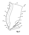
- FIG. 2 is a side view of a hybrid metal fan blade having a dovetail root and a sheath disposed over the leading edge of the metal airfoil body.
- FIG. 3A is a cross-section of the airfoil shown in FIG. 2
- FIG. 3B is an exploded cross-section of the airfoil shown in FIG. 2 .
- Turbofan engine 10 comprises several sections: fan section 12, first low-pressure compressor section 14, second high-pressure compressor section 16, combustor section 18, first high-pressure turbine section 20, second low-pressure turbine section 22, bypass section 24, low-pressure shaft 26, and high-pressure shaft 28. A portion of the atmospheric air pulled in by rotation of fan section 12 is directed toward first compressor section 14, while the remainder is directed toward bypass section 24.
- Air directed through first compressor section 14 is further compressed by second compressor section 16.
- Fuel is added and ignited in combustor section 18.
- Blades in turbine sections 20 and 22 capture a portion of the energy from passing combustion products by turning turbine rotors.
- Both fan section 12 and first compressor section 14 are rotatably linked via low-pressure shaft 26 to first low-pressure power turbine section 22.
- Second high-pressure compressor section 16 is rotatably connected to first high-pressure turbine section 22 via high-pressure shaft 28. Thrust is generated in engine 10 by the force of the air drawn in by fan section 12 and pushed through bypass section 24 (less any bleed air used for other aircraft functions), and by the force of exhaust gases exiting from second low-pressure turbine section 22.
- lighter components In a turbofan engine, lighter components generally lead to more efficient performance. If less energy is expended to move internal engine parts, more energy is available for useful work. At the same time, the components themselves must be strong enough to withstand operational forces, and types of failure typical for the operating environment of the engine. Safety considerations and regulations based on the frequency and/or severity of possible failure will often dictate that the engine components also be able to withstand other atypical, yet foreseeable events. Because stronger and lighter components are often more expensive, a balance must be struck between efficiency, safety, and cost.
- blades in fan section 12 are the first line of defense for engine 10 and are highly susceptible to both small and large scale damage from objects pulled in with the surrounding air, including bird impact damage.
- Small scale blade damage causes performance deterioration and increases the number of potential crack initiation sites, while large scale damage includes blade deformation and failure. Small impacts can also lead to large scale damage by serving as crack initiation sites. Larger impacts, such as ingestion of birds can cause one or more blades to deform or break in a single event. Regulations are in place to limit the frequency and severity of single event failures because of the increased risk of emergency landings and catastrophic failure.
- Blades made entirely from high-strength materials such as titanium or titanium alloys like Ti-6Al-4V, have been proven to offer sufficient hardness to resist erosion and foreign object damage. But titanium alloys are often expensive to purchase and manipulate into a finished blade. And while titanium has a relatively low density compared to a number of metals, the weight of titanium fan blades are significant contributors to overall engine weight. Fiber composites offer significant weight savings relative to titanium and its alloys, but are far more expensive and do not offer the same resiliency.
- Another technique of reducing weight of a blade is to use a lower-density metallic material for the airfoil body.
- composite blades are extremely light, but are far more complex and expensive to produce relative to titanium blades. Like hollow metal blades, small composite blades do not generally achieve sufficient weight savings to merit the additional complexity and cost.
- Forming the blade from a lightweight metallic material can reduce cost and weight over a titanium blade. But without additional support or reinforcement, airfoils made solely from most lightweight metals or alloys do not offer sufficient strength and longevity for long-term use.
- Blades made solely of 6XXX- or 7XXX-series aluminum alloys are lighter in weight and less costly to produce than titanium blades.
- unprotected aluminum blades are susceptible to rapid deterioration and shorter lifecycles under normal operating conditions from damage caused by small and large scale impacts as described above.
- Small-scale deterioration typically consists of pitting, nicks, dings, and erosion from sand, rain, and small runway debris.
- Air is drawn into engine 10 by fan section 12, air is forced chordwise over a leading edge of the blades. The air frequently brings debris in that bombard the blades and compromise their aerodynamic shape, causing blades to depart significantly from their design. When blades lose their shape, efficiency decreases and fuel consumption increases.
- Reinforcing and protecting leading portions of a lightweight blade can reduce the weight of the blade while meeting or exceeding current design and safety requirements.
- the following figures describe blades that can be adapted for use in example dual-spool engine 10 shown in FIG. 1 .
- the example blades described below can also be readily adapted for engines having any number of spools, such as engines with single spool or three-spool construction.
- FIG. 2 A side view of exemplary blade 30 is shown in FIG. 2 , which includes cross section 3-3. As seen in FIG. 2 , three parts are joined to form blade 30: airfoil 32, sheath 34, and root 36. Blade 30 has inner and distal spanwise sheath sections 34A and 34B, respectively, leading edge 38, trailing edge 40, and suction surface 42. Blade 30 also includes platform 46, tip edge 48, sheath head section 50, sheath flank 52A, along with forward airfoil edge 54 and sheath inner end 56. Pressure surface 44 and sheath flank 52B are at the rear of blade 30 (not visible; shown in FIGS. 3A-3B ).
- Leading edge 38 and trailing edge 40 extend generally spanwise in a curved manner from platform 46 to tip edge 48. Air flows chordwise from leading edge 38 over suction surface 42 and pressure surface 44, meeting at trailing edge 40.
- Root 36 links blade 30 at platform 46 to a disk or rotor (not shown) in fan section 12. The disk is connected, either directly or through a gear train, to a power shaft, such as low-pressure shaft 26 powered by low-pressure turbine section 22 as shown in FIG. 1 .
- root 36 is shown as a "dovetail" root; however such an arrangement is not required for the present invention.
- blade 30 can have a different configuration of root 36, or root 36 can be incorporated with the disk in what is known in the art as an integral rotor blade configuration.
- Sheath 34 covers a portion of airfoil 32 proximal forward airfoil edge 54, extending spanwise over at least a part of the length of leading edge 38 between platform 46 and tip edge 48.
- Forward airfoil edge 54 is represented by a broken line extending spanwise along sheath 34.
- Sheath 34 is divided into two spanwise regions by a chordwise broken line proximal platform 46.
- Sheath 34 includes outer sheath region 34A, located distal from platform 46, and inner sheath region 34B, located proximal platform 46.
- Airfoil 32 is formed of a lightweight metallic material such as one described below. To achieve the desired weight savings, airfoil 32 has a lower density than current titanium and titanium alloy blades. For example, titanium alloy Ti-6Al-4V, frequently used in aircraft blades, has a density of about 0.16 Ib/in 3 (4.4 g/cm 3 ). In some embodiments, the lightweight material forming airfoil 32 has a density of about 0.07-0.14 Ib/in 3 (1.9-3.9 g/cm 3 ), or about 10%-60% less than example Ti-6Al-4V.
- the lightweight material has a density of about 0.08-0.12 Ib/in 3 (2.2-3.3 g/cm 3 ), or about 25-50% less than Ti-6Al-4V.
- wrought aluminum alloys including 6XXX- and 7XXX- series alloys, range in density from about 0.09-0.11 Ib/in 3 (2.5-3.0 g/cm 3 ). In this example, therefore, wrought aluminum alloys result in a weight savings of about 30-45% over Ti-6Al-4V for the airfoil 32 portion of blade 30 for an equivalent volume of material.
- airfoil 32 With the reduced density of the airfoil 32 material, such as an aluminum alloy, a corresponding loss in strength in airfoil 32 is also likely due to the use of a lower strength material. However, with the addition of sheath 34, some loss of strength is acceptable in airfoil portion 32. While airfoil 32 must have a significant amount of structural integrity to support sheath 34 and be stiff enough to withstand the various forces in engine 10, sheath 34 provides reinforcement of airfoil 32, giving blade 30 sufficient strength to meet applicable design and regulatory standards.
- Ti-6Al-4V alloys have yield strengths of about 120 ksi (830 MPa), though this value depends in part on the time and temperature of heat treatment.
- the lightweight metallic material forming airfoil 32 has a yield strength between about 45-110 ksi (310-760 MPa), or about 10-60% less than example Ti-6Al-4V.
- the lightweight metallic material has a yield strength between about 55-95 ksi (380-650 MPa), or about 20-50% less than example Ti-6Al-4V.
- airfoil 32 is formed from a 7XXX-series aluminum alloy having a yield strength between about 65-80 ksi (410-550 MPa), or about 30-45% less than example alloys in class Ti-6Al-4V.
- sheath 34 is formed of a high-strength metallic material.
- this is a titanium alloy.
- sheath 34 is formed from a titanium alloy that includes aluminum and vanadium.
- this is a Ti-6Al-4V alloy.
- Ti-6Al-4V alloys have yield strengths ranging up to about 120 ksi (830 MPa) but are much heavier than the lightweight airfoil material.
- other high-strength metallic materials used in aircraft engines are also suitable for sheath 34.
- Such examples also include nickel or its alloys. In other examples, the nickel alloy also contains cobalt, aluminum, or both.
- Sheath 34 covers airfoil 32 proximate leading edge 38, protecting airfoil 32 from foreign object damage described above. Sheath 34 gives blade 30 a significant amount of strength, even when airfoil 32 is made of a lightweight and more ductile material like an aluminum alloy. Substituting a lighter material in airfoil 32 improves both initial raw material costs and engine efficiency by reducing the overall weight of blade 30. The reduced weight also allows for additional volume of sheath 34 proximate airfoil forward edge 54, while still saving weight overall in blade 30. Additional material on sheath 34 improves repairability of blade 30, as will be described in more detail with reference to FIG. 3B .
- sheath 34 extends across substantially the entire length of leading edge 38.
- a small portion of airfoil forward edge 54 proximate platform 46 forms the remainder of blade leading edge 38 in FIG. 2 as described below.
- sheath 34 only extends over a part of the spanwise length of leading edge 38.
- sheath 34 also covers a portion of the surface area of suction surface 42 proximate leading edge 38.
- sheath 34 also covers a corresponding portion of the surface area of pressure surface 44.
- sheath 34 will vary depending on a number of factors as described below, including the size and shape of blade 30.
- the size and shape of blade 30 depend on the size and operating envelope of engine 10, which is itself often selected by the purchaser or end user of an aircraft utilizing engine 10.
- engine 10 measures about 70 inches (178 cm) in overall diameter.
- blades 30 measure between about 24-32 inches (60-81 cm) spanwise from platform 46 to tip edge 48, and about 8-16 inches (20-40 cm) chordwise from leading edge 38 to trailing edge 40 at various points along the spanwise length of blade 30.
- chordwise dimension of blades 30 there is substantial variation in the chordwise dimension of blades 30, particularly because suction surface 42 is by definition longer than pressure surface 44, and both surfaces generally are longer chordwise closer to tip edge 48. Therefore, for simplicity and ease of illustration, an average chordwise dimension of about 12 inches (30 cm) will be used as a convenient reference to calculate examples of relative percentages of various components of blade 30. However, the percentages will vary along different locations of blade 30 in this and other embodiments.
- sheath 34 extends spanwise from tip edge 48 to a point proximate platform 46, defined by sheath inner end 56.
- sheath 34 ends at inner end 56, just short of platform 46 to simplify production of sheath 34.
- Blade 30 is thicker proximate platform 46 than in other portions of blade 30 in order to engage with dovetail root 36. Covering this thicker portion with sheath 34 complicates production of blade 30.
- dovetail root 36 reinforces blade 30 proximate platform 46 making reinforcement of platform 46 by sheath 34 redundant.
- the approximate distance between sheath root end 34A of sheath 34 and root 36 is about 0.5 inches (1.3 cm). This distance can vary based on the size and curvature of blade 30.
- other configurations of root 36 or other considerations can indicate that sheath 34 is to be extended over the remainder of airfoil forward edge 54 to platform 46.
- platform 46 is shown in FIG. 2 as integral with airfoil 32.
- platform 46 can alternatively be made separate from airfoil 32.
- the curvature and dimension of airfoil 32 proximate root 36 can simplify extension of sheath 34 to root end 56 without interference of integral platform 46.
- Sheath head section 50 of sheath 34 extends forward (i.e., into the oncoming air stream) away from airfoil 32 and forms leading edge 38. Sheath head section 50 provides stiffness and resiliency in the event of a direct or near-direct strike from a foreign object and minimizes damage to the underlying airfoil 32.
- sheath 34 also has two spanwise sections where its dimensions vary, defined by outer sheath region 34A and inner sheath region 34B.
- outer sheath region 34A the chordwise dimension of sheath head section 50 is substantially constant.
- inner region 34B the chordwise dimension of forward sheath head section 50 tapers between the dimension seen in distal region 34A and the dimension at sheath inner end 56. The difference in the chordwise dimension of head section 50 can be seen from the following example.
- sheath head section 50 extends forwardly chordwise (i.e. into the oncoming air) about one inch (2.5 cm) from airfoil forward edge 54 to leading edge 38, or about 8% of the example average chordwise dimension noted above (about 12 inches/30 centimeters).
- this chordwise dimension is substantially constant along the entire spanwise length of distal region 34A.
- the chordwise dimension of sheath head section 50 is about 0.4 inches (10 cm), or about 3% of the average chordwise dimension of blade 30.
- head section 50 has a chordwise dimension tapering between about 3/8 inch (.10 cm) and about one inch (2.5 cm). Therefore, in this example, over the spanwise length of sheath 34, the chordwise dimension of sheath head section 50 is at least about 3% of the chordwise dimension of blade 30, as is the case in inner region 34B.
- the chordwise dimension of head section 50 is at least about 8% of the chordwise dimension of blade 30. To ensure proper weight balancing, weight savings, and centrifugal strength of blade 30 proximate platform 46, the chordwise length of sheath head section 30 does not exceed about 20% of the average chordwise dimension of blade 30.
- spanwise tapering distance is provided in inner region 34B.
- the spanwise dimension of inner sheath region 34B is approximately 5%-25% of the total spanwise dimension of sheath 34.
- the spanwise dimension is about 10%-20% of the total spanwise length of sheath 34.
- the spanwise dimension is about 15% of the total spanwise length of sheath 34.
- chordwise dimension of forward sheath head section 50 is substantially constant through outer region 34A and tapering through inner region 34B to inner end 56. Such an arrangement is not present in all embodiments.
- Other configurations of root 36 or a desire for increased foreign object protection at certain locations along leading edge 38 may require enlarging the chordwise and/or thickness dimensions of sheath head section 50 at various locations along leading edge 38.
- Sheath 34 also includes flanks 52A and 52B extending substantially chordwise rearwardly from sheath head section 50 toward trailing edge 40.
- Flanks 52A and 52B extend over a portion of the area defined by one or both of suction surface 42 and pressure surface 44, respectively.
- Flanks 52A and 52B provide additional bonding or interface area for sheath 34 and protect blade 30 from indirect impacts proximate leading edge 38.
- the dimensions of flanks 52A and 52B, as well as other parts are more visible in the cross-section shown in FIGS. 3A-3B .
- FIG. 3A depicts a partial cross-section of blade 30 taken across line 3-3 of FIG. 2 .
- Blade 30 includes airfoil 32, sheath 34, leading edge 38, suction surface 42, pressure surface 44, sheath head section 50, sheath flanks 52A and 52B, airfoil forward edge 54, and sheath receiving surface 58.
- Sheath receiving surface 58 is located on airfoil 32 proximate leading edge 38 and includes a portion of suction surface 42 and pressure surface 44.
- Flanks 52A and 52B extend back from head section 50 over portions of suction surface 42 and pressure surface 44 proximate leading edge 38.
- sheath head section 50 replaces a portion of airfoil 32 near its forward edge, while in other embodiments, head section 50 increases the chordwise length of blade 30 by an amount equal to chordwise dimension of head section 50. This ensures aerodynamic continuity between airfoil portion 32 and sheath portion 34.
- sheath head section 50 varies in its chordwise dimension along leading edge 38, including proximate platform 46.
- Flanks 52A and 52B can also vary in their chordwise lengths and respective thicknesses.
- flank 52A comprises about 1-2 inches (2.5-5.0 cm) of the chordwise dimension of suction surface 42
- flank 52B comprises about 1.2-2.4 inches (3.0-6.0 cm) of the chordwise dimension of pressure surface 44. Therefore, in this example, flank 52A constitutes about 8-16% of an average chordwise dimension of suction surface 42 and flank 52B constitutes about 10-20% of an average chordwise dimension of pressure surface 44 away from platform 46.
- flanks 52A and 52B comprise up to about 30% of the average chordwise dimension of blade 30 along either suction surface 42 or pressure surface 44.
- sheath 34 does not comprise more than about 50% of the average chordwise dimension of blade 30 on either suction surface 42 or pressure surface 44.
- flanks 52A and 52B measure about 0.02 inches (0.5 mm) in the blade thickness direction at the junction with head section 50, tapering to about 0.01 inches (0.3 mm) at points on sheath 34 farthest from leading edge 38.
- the chordwise lengths of flanks 52A and 52B are also substantially constant in this example in distal region 34A, while in inner sheath region 34B, those chordwise lengths taper toward airfoil forward edge 54.
- the chordwise lengths of flanks 52A and 52B taper from the lengths in outer span region 34A down to about 0.3-0.4 inches (7-10 mm) proximate sheath root end 56.
- flank 52B on pressure surface 44 can optionally be longer and/or thicker than flank 52A on suction surface 42.
- flank 52B on pressure surface 44 provides more surface and bonding area for sheath 34.
- the motion of blade 30 tends to force the bird to strike closer to pressure side 44, bending blade 30 opposite its regular curvature.
- Sheath head portion 50 is pushed toward suction surface 42 bending and shearing flank 52B away from pressure surface 44. Therefore, a larger bonding surface created by increasing the surface area of flank 52B will resist shearing of sheath 34 away from airfoil 32, increasing the likelihood that blade 30 can withstand a bird strike.
- flank 52A on suction surface 42 should have the same or greater chordwise length than flank 52B on pressure surface 44.
- one skilled in the art may decide to build blade 30 to provide more protection against small-scale damage and prevent crack initiation rather than to withstand bird strikes.
- the negative pressure caused by airflow over suction surface 42 is more likely to pull debris toward blade 30, increasing the risk of small-scale damage on suction surface 42.
- chordwise dimension of flanks 52A and 52B will vary at different points along the spanwise direction of leading edge 32. While FIG. 2 shows that the lengths of flanks 52A and/or 52B are substantially constant in the chordwise direction along leading edge 38, these dimensions can vary according to a range of design variables depending on the nature of the intended use of blade 30.
- One example variable includes a higher risk of damage or weakness at different points along the spanwise dimension of leading edge 38.
- forward sheath section 50 can also be longer chordwise and or thicker to provide sufficient protection for larger blades 30.
- a larger blade 30 in some embodiments is stronger than a smaller blade 30 of similar shape, and thus the above described dimensions of sheath 34 will constitute a larger proportion of the dimensions of blade 30.
- sheath 34 relative to blade 30 Another consideration in determining the dimensions of sheath 34 relative to blade 30 is the relative strength and weight of the metallic materials described above.
- metallic materials with a substantially higher strength rating when used to form airfoil portion 32, will generally require less of the stronger material at leading edge 38.
- nickel and various alloys have yield strengths between about 1.5 times to about two times that of titanium alloys like Ti-6Al-4V. In those embodiments, the dimensions of sheath 34 relative to airfoil 32 will be smaller for an otherwise equivalent blade 30.
- FIG. 3B is an exploded cross-section of blade 30 shown in FIG. 3A .
- Blade 30 in FIG. 3B also includes airfoil 32, sheath 34, leading edge 38, suction surface 42, pressure surface 44, tip edge 48, sheath head section 50, sheath flanks 52A and 52B, forward airfoil edge 54, sheath receiving surface 58, adhesive 60, and scrim sheet 62.
- airfoil 32 in some embodiments is shaped to accommodate placement of sheath 34 and minimize final processing time. This is accomplished, for example, by including sheath receiving surface 58 on airfoil 32.
- Surface 58 is a recessed portion of airfoil 32 located proximate leading edge 38, complementing the shape of sheath 34 and providing substantially uniform surfaces on completed blade 30.
- Surface 58 also will be recessed to a thickness sufficient to accommodate adhesive 60 and scrim sheet 62 described below. Recessed portion 58 can be formed during production of airfoil 32 or later during processing and before engagement of sheath 34 to airfoil 32.
- sheath 34 can vary both in the thickness of head section 50, as well as the thickness and chordwise dimension of flanks 52A and 52B, surface 58 must be adapted accordingly.
- the edge of head section 50 that will eventually form leading edge 38 can be formed as near as possible to the final desired shape of leading edge 38 to minimize machining time and increase material yields by decreasing waste.
- the dimensions of the recessed portion defining receiving surface 58 can also be adjusted to account for the thickness and type of bonding material used between airfoil 32 and sheath 34, described below.
- suction surface 42 and flank 52A are substantially flush with each other once combined.
- pressure surface 44 and flank 52B are also substantially flush, leaving minimal gaps or changes in surface elevation chordwise along suction surface 42 and pressure surface 44. Any remaining gaps or undesired elevation changes can be mitigated by finish machining of blade 30 before placing it into service.
- the application of corrosion and erosion resistant coatings to the sheath and airfoil surfaces also assists in smoothing any gaps or evening out undesired elevation changes. Addition of such coatings to airfoil 32 and sheath 34 also helps to reduce damage otherwise caused by continuous bombardment of blade 30 with sand, rain, and small runway debris pulled into engine 10. Erosion resistant coatings can prevent these and other small foreign objects from reaching the metal surfaces of airfoil 32 and sheath 34, hindering formation of small nicks and dings. Corrosion resistant coatings prevent the spread of corrosion outside of areas that have been damaged despite other protective measures.
- Sheath 34 is held in place on surface 58 by adhesive 60.
- adhesive 60 A variety of commercially available aerospace-quality metal-bonding adhesives are suitable, including several epoxy- and polyurethane-based adhesive films. In some embodiments, the adhesive is heat-cured via autoclave or other similar means. Examples of suitable bonding agents include type EA9628 epoxy adhesive available from Henkel Corporation, Hysol Division, Bay Point, Calif. and type AF163K epoxy adhesive available from 3M Adhesives, Coatings & Sealers Division, St. Paul, Minn.
- the adhesive is a film, which also contributes a minute amount of thickness of blade 30 proximate sheath 34.
- a layer of adhesive film 60 is about 0.005-0.010 inch (1.2-2.5 mm) thick.
- a film-based adhesive 60 allows for generally uniform application, leading to a predictable thickness to be accounted for in sizing flanks 52A and 52B, as well as the thickness of airfoil 32 proximate forward airfoil edge 54.
- Certain adhesives 60 are compatible with scrim sheet 62.
- Scrim sheet 62 provides dielectric separation between airfoil 32 and sheath 34, preventing galvanic corrosion between the two different metal surfaces of airfoil 32 and sheath 34.
- the material forming scrim sheet 62 is often determined by its compatibility with adhesive 60.
- One example scrim sheet is a flexible nylon-based layer with a thickness between about 0.005 inch (0.12 mm) and about 0.010 inch (0.25 mm) thick.
- sheath 34 As described below, bonding of sheath 34 to airfoil 32 with adhesive 60 and separating the dissimilar metals with scrim sheet 62 improves several aspects of blade 30.
- sheath 34 is produced separately and the contact surfaces of airfoil 32 and sheath 34 are properly prepared, complex high temperature bonding and forming processes are not necessary, and thus no deformation is caused around leading edge 38, allowing airfoil 32 to retain its shape and integrity during joining of sheath 34.
- Diffusion bonding is inappropriate to directly form and place sheath 34 over leading edge 38 because the process can compromise the structural integrity of airfoil 32 and thus the entire blade 30.
- the high temperatures of diffusion bonding a titanium sheath have been known to cause undesired phase transitions and boundaries when done in close proximity to key portions of airfoil 32, such as proximate forward airfoil edge 54. Such transitions weaken the microstructure and damage airfoil 32 if proximate forward airfoil edge 54.
- sheath 34 so long as there is sufficient strength in sheath head portion 50 and sufficient bonding area for flanks 52A and 52B as described above, can be separately diffusion bonded or electroformed and attached using adhesive 60 and, if necessary, scrim sheet 62.
- Electroformed sheaths have been used in certain propeller and helicopter blades to provide wear and erosion resistance. However, such technology cannot be easily adapted to blades 30 for use in a turbofan engine such as engine 10. Electroformed nickel sheaths presently in use on helicopter and propeller blades are provided for wear resistance only and are not built to withstand the rigors of a turbofan engine, including the greater number and speed of foreign objects striking the blades. For example, they do not have adequate strength or thickness along the leading edge and their flanks do not have sufficient bonding area to prevent shearing away of a sheath.
- Helicopter and propeller blades also have a comparatively large radius at their leading edge, which decreases their aerodynamic efficiency relative to what is required for turbofan blades.
- the radius at leading edge 38 is less than about 0.5 mils (125 ⁇ m). In other embodiments, the radius is less than about 0.4 mils (100 ⁇ m).
- aerodynamic efficiency is maximized as that radius approaches zero.
- electroforming a sheath with such a small radius at leading edge 38 and a large thickness proximate airfoil leading edge 54 requires sheath head portion 50 to be much longer and thicker in the chordwise direction. Creating sheath 34 with such relative sizes via electroforming is difficult and impractical, though not impossible.
- electroforming is possible with a relatively small number of materials otherwise suitable for aircraft applications.
- substantially pure metals and certain alloys like Ni-Co are readily electroformed into an article while maintaining the desired material properties.
- titanium alloys used in aircraft applications such as Ti-6Al-4V, have unique microstructures that contribute substantially to their strength and relatively light weight. The temperatures necessary to properly crystallize and anneal these microstructures are not possible during an electroforming process. While the materials are limited, sheaths 34 that are electroformed separately as described in the previous paragraph can also be adhesively bonded to airfoil 32 so long as the material is conducive to being electroformed into the desired shape.
- sheath 34 also result in improved repairability of blade 30. Having a larger volume of excess high-strength material on sheath 34 at leading edge 38 allows for more strength and resiliency, as well as extending the serviceable life of blade 30. Blades 30 are susceptible to nicks and erosion as well as bird strikes. As is known in the art, nicks and other small imperfections can serve as crack initiation sites, and can occur despite the inclusion of various erosion and corrosion resistant coatings.
- blades 30 can be repaired, often several times, by machining out dents and other sharp corners. This repair is common in titanium-based blades to increase their serviceable life before being recycled into new blades or into other articles. In most titanium blades or sheaths, there is often a limited amount of excess material because of the inherent motivation to reduce weight and the physical constraints of producing sheaths with large thickness via processes like electroforming. But in blade 30, substituting a lower density metallic material in airfoil 32 provides substantial weight savings without sacrificing overall strength as previously described. This substantial weight savings provides some leeway for the size of sheath 34 to be increased in its chordwise and thickness dimensions while still achieving significant weight savings in blade 30.
- Airfoil 32 is formed from a lightweight metallic material according to the description above, such as from an aluminum alloy.
- a lightweight metallic material is a 7XXX-series alloy.
- Example methods of making airfoil 32 include forging, casting, rolling or machining.
- Airfoil 32 is hollow or solid depending on relevant design requirements such as engine size and relative material and processing costs.
- Airfoil 32 has at least a forward edge, a first surface, and a second surface. Hollow airfoils 32 can be formed by any method, such as by diffusion bonding two metal plates around their perimeters.
- Sheath 34 is formed from a high-strength metallic material according to the description above, such as from a titanium or nickel alloy.
- a titanium or nickel alloy is Ti-6Al-4V.
- Sheath 34 is also fabricated using one or more conventional metal processing techniques, such as casting, forging, rolling, or machining, and can be manufactured directly into its final shape with first flank 52A and second flank 52B extending chordwise from sheath head section 50.
- Certain embodiments of sheath 34 such as those formed from nickel or nickel-cobalt alloys, can be electroformed or diffusion bonded separately from airfoil section 32.
- Airfoil section 32 is adapted to accommodate sheath 34 by forming sheath receiving surface 58.
- airfoil 32 is adapted by removing sufficient material from proximate leading edge 38, including suction surface 42 and pressure surface 44 to create a recessed portion defined as sheath receiving surface 58.
- surface 58 can be formed during production of airfoil 32, for example if airfoil 32 is made by casting.
- sheath 34 is put into place, covering surface 58.
- Sheath 34 is then bonded to surface 58 using certain adhesives suitable for aerospace applications.
- suitable adhesives include Henkel EA9628 and 3M type AF163K epoxy adhesives, available as noted above.
- Bonding is facilitated and strengthened by preparing surfaces with appropriate cleaning and texturing. The exact preparation is determined by the choice of adhesive. Curing of the adhesive, if necessary, is also determined by the type of adhesive chosen. Preparation of sheath 34 as well as attachment surface 58 of airfoil body 32 can be done by a combination of milling, chemical processing or other suitable means. After placement of the adhesive and scrim sheet, the adhesive is cured. As one example, the adhesive films listed above are heat cured, such as by autoclaving.
- blade 30 is machined or otherwise formed into its final desired shape. If airfoil 32 and sheath 34 are formed nearly into their final shapes and bonding is successful, only final machining is required. Alternatively, in certain embodiments, the components are machined prior to bonding such that major surfaces of blade 30 have minimal elevation changes and gaps immediately after bonding, making finish machining unnecessary.
- Final processing can also include covering blade 30 with erosion or corrosion resistant coatings. These coatings protect the surfaces of blade 30, including at any remaining gaps between airfoil 32 and sheath 34.
- the exact shape will depend on the particular flow characteristics desired for engine 10. This disclosure can be readily adapted to blades 30 having a wide variety of flow patterns. In addition, one or more of the preceding steps may be omitted, combined, reordered, or adapted to a particular set of circumstances without departing from the scope and spirit of the invention.
- hybrid metal blade 30 greatly improves the performance of a blade made of a lightweight metal, such as an aluminum alloy, while saving a significant amount of cost and weight over a titanium alloy blade. These improvements are seen while limiting safety, maintenance, and downtime costs as described herein.
- Blade 30 was tested in a simulation of a medium-sized bird strike. Test panels with and without sheath 34 were used to compare the strength and performance of blade 30. Airfoil body 32 was modeled using a 7XXX-series aluminum alloy sheet, and sheath 34 was modeled with titanium alloy Ti-6Al-4V. A projectile weighing about 2.5 pounds (1.1 kg), traveling at about 750 feet per second, struck the test panels at an angle of incidence of about 26°.
- test panel with simulated sheath 34 exhibited between about 3-6% leading edge line strain.
- unprotected aluminum test panel exhibited about 20-25% leading edge line strain after being struck by the test projectile.
Applications Claiming Priority (1)
| Application Number | Priority Date | Filing Date | Title |
|---|---|---|---|
| US12/713,867 US9157327B2 (en) | 2010-02-26 | 2010-02-26 | Hybrid metal fan blade |
Publications (3)
| Publication Number | Publication Date |
|---|---|
| EP2362067A2 true EP2362067A2 (fr) | 2011-08-31 |
| EP2362067A3 EP2362067A3 (fr) | 2014-09-17 |
| EP2362067B1 EP2362067B1 (fr) | 2019-01-16 |
Family
ID=43824235
Family Applications (1)
| Application Number | Title | Priority Date | Filing Date |
|---|---|---|---|
| EP11250226.5A Active EP2362067B1 (fr) | 2010-02-26 | 2011-02-28 | Aube de soufflante de métal hybride |
Country Status (3)
| Country | Link |
|---|---|
| US (1) | US9157327B2 (fr) |
| EP (1) | EP2362067B1 (fr) |
| SG (2) | SG10201502327WA (fr) |
Cited By (10)
| Publication number | Priority date | Publication date | Assignee | Title |
|---|---|---|---|---|
| EP2685047A1 (fr) * | 2012-07-13 | 2014-01-15 | Alstom Technology Ltd | Aube/pale modulaire pour turbine à gaz et turbine à gaz avec une telle aube/pale |
| GB2507146A (en) * | 2012-07-24 | 2014-04-23 | Snecma | Composite turbine engine blade, eg fan blade, with a structural reinforcement on its leading edge |
| WO2014158245A1 (fr) * | 2013-03-14 | 2014-10-02 | Hodgson Benedict N | Profil aérodynamique avec renfort de bord d'attaque |
| WO2014196987A2 (fr) | 2012-06-21 | 2014-12-11 | United Technologies Corporation | Pale de ventilateur métallique hybride |
| WO2015069335A2 (fr) | 2013-09-09 | 2015-05-14 | United Technologies Corporation | Pales de ventilateur et procédés de fabrication |
| EP2823085A4 (fr) * | 2012-03-08 | 2016-03-09 | United Technologies Corp | Protection de bord avant et son procédé de réalisation |
| EP2634368A3 (fr) * | 2012-02-29 | 2017-03-15 | United Technologies Corporation | Procédé de collage d'un tôle de renforcement du bord d'attaque à un corps d'une aube de soufflante |
| US9650897B2 (en) | 2010-02-26 | 2017-05-16 | United Technologies Corporation | Hybrid metal fan blade |
| EP3049635A4 (fr) * | 2013-09-17 | 2017-09-20 | United Technologies Corporation | Profil aérodynamique en aluminium pourvu d'un revêtement en titane |
| EP3332902A1 (fr) * | 2016-12-09 | 2018-06-13 | Hamilton Sundstrand Corporation | Systèmes et procédés de fabrication d'un renfort métallique d'aube de turbomachine |
Families Citing this family (58)
| Publication number | Priority date | Publication date | Assignee | Title |
|---|---|---|---|---|
| US20120021243A1 (en) * | 2010-07-23 | 2012-01-26 | General Electric Company | Components with bonded edges |
| US9587645B2 (en) * | 2010-09-30 | 2017-03-07 | Pratt & Whitney Canada Corp. | Airfoil blade |
| US9429029B2 (en) | 2010-09-30 | 2016-08-30 | Pratt & Whitney Canada Corp. | Gas turbine blade and method of protecting same |
| FR2965497B1 (fr) * | 2010-10-05 | 2013-07-12 | Snecma | Procede de realisation d'une piece metallique |
| US8449784B2 (en) * | 2010-12-21 | 2013-05-28 | United Technologies Corporation | Method for securing a sheath to a blade |
| US20130199934A1 (en) | 2012-02-06 | 2013-08-08 | United Technologies Corporation | Electroformed sheath |
| US9427835B2 (en) | 2012-02-29 | 2016-08-30 | Pratt & Whitney Canada Corp. | Nano-metal coated vane component for gas turbine engines and method of manufacturing same |
| US10260351B2 (en) * | 2012-03-16 | 2019-04-16 | United Technologies Corporation | Fan blade and method of manufacturing same |
| FR2989991B1 (fr) * | 2012-04-30 | 2016-01-08 | Snecma | Renfort structurel metallique d'aube de turbomachine |
| US20140010663A1 (en) * | 2012-06-28 | 2014-01-09 | Joseph Parkos, JR. | Gas turbine engine fan blade tip treatment |
| DE102012015137A1 (de) * | 2012-07-30 | 2014-02-13 | Rolls-Royce Deutschland Ltd & Co Kg | Niedermodulige Gasturbinenverdichterschaufel |
| US8876482B2 (en) * | 2012-09-11 | 2014-11-04 | United Technologies Corporation | Electrical grounding for blade sheath |
| US9322283B2 (en) | 2012-09-28 | 2016-04-26 | United Technologies Corporation | Airfoil with galvanic corrosion preventive shim |
| US20140219808A1 (en) * | 2012-10-01 | 2014-08-07 | United Technologies Corporation | Sheath with extended wings |
| US10072507B2 (en) | 2012-10-25 | 2018-09-11 | United Technologies Corporation | Redundant airfoil attachment |
| US9453418B2 (en) * | 2012-12-17 | 2016-09-27 | United Technologies Corporation | Hollow airfoil with composite cover and foam filler |
| US9359906B2 (en) | 2012-12-18 | 2016-06-07 | United Technologies Corporation | Rotor blade root spacer with a fracture feature |
| US9422819B2 (en) | 2012-12-18 | 2016-08-23 | United Technologies Corporation | Rotor blade root spacer for arranging between a rotor disk and a root of a rotor blade |
| EP2946080B1 (fr) * | 2013-01-17 | 2018-05-30 | United Technologies Corporation | Entretoise d'emplanture de pale de rotor équipée d'élément de prise |
| US20160003060A1 (en) * | 2013-03-07 | 2016-01-07 | United Technologies Corporation | Hybrid fan blades for jet engines |
| WO2014137448A1 (fr) * | 2013-03-08 | 2014-09-12 | United Technologies Corporation | Pales de ventilateur à gaines de protection et écrans galvaniques |
| US20160010470A1 (en) * | 2013-03-14 | 2016-01-14 | United Technologies Corporation | Frangible Sheath for a Fan Blade of a Gas Turbine Engine |
| WO2014143260A1 (fr) * | 2013-03-15 | 2014-09-18 | United Technologies Corporation | Procédé de fabrication de gaine de bord d'attaque |
| US10323521B2 (en) * | 2013-03-15 | 2019-06-18 | United Technologies Corporation | Hybrid fan blade biscuit construction |
| WO2014143262A1 (fr) * | 2013-03-15 | 2014-09-18 | United Technologies Corporation | Gaine de bord d'attaque allongée localement pour pale à profil aérodynamique de ventilateur |
| WO2014143265A1 (fr) * | 2013-03-15 | 2014-09-18 | United Technologies Corporation | Structure à insertion pour pale de soufflante hybride |
| EP3019710A4 (fr) * | 2013-07-09 | 2017-05-10 | United Technologies Corporation | Ventilateur en polymère plaqué |
| WO2015006421A1 (fr) | 2013-07-09 | 2015-01-15 | United Technologies Corporation | Article polymère sous encapsulation métallique |
| WO2015017095A2 (fr) | 2013-07-09 | 2015-02-05 | United Technologies Corporation | Coiffe polymère plaquée |
| US10458428B2 (en) | 2013-09-09 | 2019-10-29 | United Technologies Corporation | Fan blades and manufacture methods |
| EP3049631A4 (fr) * | 2013-09-27 | 2017-06-07 | United Technologies Corporation | Ensemble pale de ventilateur |
| WO2015047752A1 (fr) | 2013-09-27 | 2015-04-02 | United Technologies Corporation | Ensemble pale de soufflante |
| EP3049629B8 (fr) * | 2013-09-27 | 2021-04-07 | Raytheon Technologies Corporation | Ensemble aube |
| WO2015047949A1 (fr) | 2013-09-27 | 2015-04-02 | United Technologies Corporation | Ensemble de pale de ventilateur |
| US20160177732A1 (en) * | 2014-07-22 | 2016-06-23 | United Technologies Corporation | Hollow fan blade for a gas turbine engine |
| US9745851B2 (en) | 2015-01-15 | 2017-08-29 | General Electric Company | Metal leading edge on composite blade airfoil and shank |
| US11149642B2 (en) | 2015-12-30 | 2021-10-19 | General Electric Company | System and method of reducing post-shutdown engine temperatures |
| US11053861B2 (en) | 2016-03-03 | 2021-07-06 | General Electric Company | Overspeed protection system and method |
| US10677259B2 (en) * | 2016-05-06 | 2020-06-09 | General Electric Company | Apparatus and system for composite fan blade with fused metal lead edge |
| US10337405B2 (en) | 2016-05-17 | 2019-07-02 | General Electric Company | Method and system for bowed rotor start mitigation using rotor cooling |
| US10138732B2 (en) | 2016-06-27 | 2018-11-27 | United Technologies Corporation | Blade shield removal and replacement |
| RU2639264C1 (ru) * | 2016-07-05 | 2017-12-20 | Публичное акционерное общество "ОДК-Уфимское моторостроительное производственное объединение" (ПАО "ОДК-УМПО") | Лопатка турбомашины |
| US10815797B2 (en) | 2016-08-12 | 2020-10-27 | Hamilton Sundstrand Corporation | Airfoil systems and methods of assembly |
| US10583933B2 (en) | 2016-10-03 | 2020-03-10 | General Electric Company | Method and apparatus for undercowl flow diversion cooling |
| US10718350B2 (en) * | 2016-11-24 | 2020-07-21 | Pratt & Whitney Canada Corp. | Fan blade with galvanic separator |
| CN109723671A (zh) * | 2017-10-27 | 2019-05-07 | 中国航发商用航空发动机有限责任公司 | 一种复合材料风扇叶片金属加强边的制造方法 |
| US10731470B2 (en) * | 2017-11-08 | 2020-08-04 | General Electric Company | Frangible airfoil for a gas turbine engine |
| US10947993B2 (en) | 2017-11-27 | 2021-03-16 | General Electric Company | Thermal gradient attenuation structure to mitigate rotor bow in turbine engine |
| JP6735299B2 (ja) * | 2018-03-09 | 2020-08-05 | 三菱重工業株式会社 | 複合材翼、前縁金属カバー形成ユニット、複合材翼の製造方法 |
| GB201810885D0 (en) * | 2018-07-03 | 2018-08-15 | Rolls Royce Plc | High efficiency gas turbine engine |
| GB201903261D0 (en) | 2019-03-11 | 2019-04-24 | Rolls Royce Plc | Efficient gas turbine engine installation and operation |
| GB201903262D0 (en) | 2019-03-11 | 2019-04-24 | Rolls Royce Plc | Efficient gas turbine engine installation and operation |
| GB201903257D0 (en) | 2019-03-11 | 2019-04-24 | Rolls Royce Plc | Efficient gas turbine engine installation and operation |
| KR102283974B1 (ko) * | 2020-01-06 | 2021-07-29 | 이은일 | 송풍기 날개차의 날개 |
| US11725524B2 (en) | 2021-03-26 | 2023-08-15 | General Electric Company | Engine airfoil metal edge |
| US20230128806A1 (en) * | 2021-10-27 | 2023-04-27 | General Electric Company | Airfoils for a fan section of a turbine engine |
| US11879411B2 (en) | 2022-04-07 | 2024-01-23 | General Electric Company | System and method for mitigating bowed rotor in a gas turbine engine |
| US11767607B1 (en) | 2022-07-13 | 2023-09-26 | General Electric Company | Method of depositing a metal layer on a component |
Family Cites Families (23)
| Publication number | Priority date | Publication date | Assignee | Title |
|---|---|---|---|---|
| US2431184A (en) * | 1943-09-23 | 1947-11-18 | United Aireraft Corp | Composite blade |
| US3762835A (en) * | 1971-07-02 | 1973-10-02 | Gen Electric | Foreign object damage protection for compressor blades and other structures and related methods |
| US4006999A (en) * | 1975-07-17 | 1977-02-08 | The United States Of America As Represented By The Administrator Of The National Aeronautics And Space Administration | Leading edge protection for composite blades |
| US4738594A (en) | 1986-02-05 | 1988-04-19 | Ishikawajima-Harima Jukogyo Kabushiki Kaisha | Blades for axial fans |
| US4842663A (en) * | 1988-04-29 | 1989-06-27 | Kramer Leslie D | Steam turbine blade anti-erosion shield and method of turbine blade repair |
| US5141400A (en) * | 1991-01-25 | 1992-08-25 | General Electric Company | Wide chord fan blade |
| US5490764A (en) | 1994-05-23 | 1996-02-13 | General Electric Company | Unshrouded blading for high bypass turbofan engines |
| US5486096A (en) * | 1994-06-30 | 1996-01-23 | United Technologies Corporation | Erosion resistant surface protection |
| US5520516A (en) | 1994-09-16 | 1996-05-28 | Praxair S.T. Technology, Inc. | Zirconia-based tipped blades having macrocracked structure |
| US5908285A (en) | 1995-03-10 | 1999-06-01 | United Technologies Corporation | Electroformed sheath |
| US5674370A (en) | 1995-03-31 | 1997-10-07 | Optical Radiation Corporation | Method of electroforming an abrasion shield |
| US5866272A (en) | 1996-01-11 | 1999-02-02 | The Boeing Company | Titanium-polymer hybrid laminates |
| US5725354A (en) | 1996-11-22 | 1998-03-10 | General Electric Company | Forward swept fan blade |
| US5881972A (en) | 1997-03-05 | 1999-03-16 | United Technologies Corporation | Electroformed sheath and airfoiled component construction |
| US6037004A (en) | 1997-12-19 | 2000-03-14 | United Technologies Corporation | Shield and method for protecting an airfoil surface |
| US6004101A (en) | 1998-08-17 | 1999-12-21 | General Electric Company | Reinforced aluminum fan blade |
| US6341747B1 (en) * | 1999-10-28 | 2002-01-29 | United Technologies Corporation | Nanocomposite layered airfoil |
| DE10110102C2 (de) | 2000-12-18 | 2002-12-05 | Deutsch Zentr Luft & Raumfahrt | Rotorschaufel |
| US6843928B2 (en) * | 2001-10-12 | 2005-01-18 | General Electric Company | Method for removing metal cladding from airfoil substrate |
| US6607358B2 (en) * | 2002-01-08 | 2003-08-19 | General Electric Company | Multi-component hybrid turbine blade |
| US7637721B2 (en) | 2005-07-29 | 2009-12-29 | General Electric Company | Methods and apparatus for producing wind energy with reduced wind turbine noise |
| US20070084527A1 (en) * | 2005-10-19 | 2007-04-19 | Stephane Ferrasse | High-strength mechanical and structural components, and methods of making high-strength components |
| US7736130B2 (en) * | 2007-07-23 | 2010-06-15 | General Electric Company | Airfoil and method for protecting airfoil leading edge |
-
2010
- 2010-02-26 US US12/713,867 patent/US9157327B2/en active Active
- 2010-12-03 SG SG10201502327WA patent/SG10201502327WA/en unknown
- 2010-12-03 SG SG2010089142A patent/SG173944A1/en unknown
-
2011
- 2011-02-28 EP EP11250226.5A patent/EP2362067B1/fr active Active
Non-Patent Citations (1)
| Title |
|---|
| None |
Cited By (15)
| Publication number | Priority date | Publication date | Assignee | Title |
|---|---|---|---|---|
| US9650897B2 (en) | 2010-02-26 | 2017-05-16 | United Technologies Corporation | Hybrid metal fan blade |
| EP2634368A3 (fr) * | 2012-02-29 | 2017-03-15 | United Technologies Corporation | Procédé de collage d'un tôle de renforcement du bord d'attaque à un corps d'une aube de soufflante |
| EP2823085A4 (fr) * | 2012-03-08 | 2016-03-09 | United Technologies Corp | Protection de bord avant et son procédé de réalisation |
| WO2014196987A2 (fr) | 2012-06-21 | 2014-12-11 | United Technologies Corporation | Pale de ventilateur métallique hybride |
| EP2867473A4 (fr) * | 2012-06-21 | 2015-08-19 | United Technologies Corp | Pale de ventilateur métallique hybride |
| EP2685047A1 (fr) * | 2012-07-13 | 2014-01-15 | Alstom Technology Ltd | Aube/pale modulaire pour turbine à gaz et turbine à gaz avec une telle aube/pale |
| GB2507146A (en) * | 2012-07-24 | 2014-04-23 | Snecma | Composite turbine engine blade, eg fan blade, with a structural reinforcement on its leading edge |
| GB2507146B (en) * | 2012-07-24 | 2017-11-08 | Snecma | Composite Turbine Engine Blade with Structural Reinforcement |
| WO2014158245A1 (fr) * | 2013-03-14 | 2014-10-02 | Hodgson Benedict N | Profil aérodynamique avec renfort de bord d'attaque |
| WO2015069335A2 (fr) | 2013-09-09 | 2015-05-14 | United Technologies Corporation | Pales de ventilateur et procédés de fabrication |
| EP3044417A4 (fr) * | 2013-09-09 | 2016-12-14 | United Technologies Corp | Pales de ventilateur et procédés de fabrication |
| US10487843B2 (en) | 2013-09-09 | 2019-11-26 | United Technologies Corporation | Fan blades and manufacture methods |
| EP3049635A4 (fr) * | 2013-09-17 | 2017-09-20 | United Technologies Corporation | Profil aérodynamique en aluminium pourvu d'un revêtement en titane |
| EP3332902A1 (fr) * | 2016-12-09 | 2018-06-13 | Hamilton Sundstrand Corporation | Systèmes et procédés de fabrication d'un renfort métallique d'aube de turbomachine |
| US10626883B2 (en) | 2016-12-09 | 2020-04-21 | Hamilton Sundstrand Corporation | Systems and methods for making blade sheaths |
Also Published As
| Publication number | Publication date |
|---|---|
| SG10201502327WA (en) | 2015-05-28 |
| SG173944A1 (en) | 2011-09-29 |
| EP2362067A3 (fr) | 2014-09-17 |
| US9157327B2 (en) | 2015-10-13 |
| EP2362067B1 (fr) | 2019-01-16 |
| US20110211967A1 (en) | 2011-09-01 |
Similar Documents
| Publication | Publication Date | Title |
|---|---|---|
| EP2362067B1 (fr) | Aube de soufflante de métal hybride | |
| US9650897B2 (en) | Hybrid metal fan blade | |
| EP2867473B1 (fr) | Aubes rotoriques pour un moteur d'aviation, et moteur d'aviation à turbine à gaz associé | |
| EP2362066B1 (fr) | Aube de soufflante creuse | |
| EP2932044B1 (fr) | Profil aérodynamique creux avec couverture composite et remplissage de mousse | |
| EP2348192B1 (fr) | Gaine d'aube de soufflante | |
| EP2540978B1 (fr) | Protection d'une aube de soufflante en aluminium | |
| US8449784B2 (en) | Method for securing a sheath to a blade | |
| CN111287802B (zh) | 多材料前缘保护器 | |
| EP2971528B1 (fr) | Pale de ventilateur creuse dotée d'une gaine d'aile allongée | |
| CA2747121A1 (fr) | Composants a bords colles | |
| EP3049635B1 (fr) | Profil aérodynamique en aluminium pourvu d'un revêtement en titane | |
| EP2540966B1 (fr) | Procédé de finition d'une aube de soufflante en aluminium | |
| EP2900922B1 (fr) | Profil aérodynamique avec cales de prévention de corrosion galvanique | |
| US20140219808A1 (en) | Sheath with extended wings | |
| EP3049630B1 (fr) | Ensemble de pale de soufflante |
Legal Events
| Date | Code | Title | Description |
|---|---|---|---|
| PUAI | Public reference made under article 153(3) epc to a published international application that has entered the european phase |
Free format text: ORIGINAL CODE: 0009012 |
|
| AK | Designated contracting states |
Kind code of ref document: A2 Designated state(s): AL AT BE BG CH CY CZ DE DK EE ES FI FR GB GR HR HU IE IS IT LI LT LU LV MC MK MT NL NO PL PT RO RS SE SI SK SM TR |
|
| AX | Request for extension of the european patent |
Extension state: BA ME |
|
| RIN1 | Information on inventor provided before grant (corrected) |
Inventor name: DEAL, JAMES L. Inventor name: HANSEN, JAMES O. Inventor name: SCHIRRA, JOHN J. Inventor name: DROZDENKO, LEE Inventor name: GRAVES, WILLIAM R. |
|
| PUAL | Search report despatched |
Free format text: ORIGINAL CODE: 0009013 |
|
| AK | Designated contracting states |
Kind code of ref document: A3 Designated state(s): AL AT BE BG CH CY CZ DE DK EE ES FI FR GB GR HR HU IE IS IT LI LT LU LV MC MK MT NL NO PL PT RO RS SE SI SK SM TR |
|
| AX | Request for extension of the european patent |
Extension state: BA ME |
|
| RIC1 | Information provided on ipc code assigned before grant |
Ipc: F01D 5/14 20060101AFI20140808BHEP Ipc: F04D 29/32 20060101ALI20140808BHEP Ipc: F04D 29/02 20060101ALI20140808BHEP |
|
| 17P | Request for examination filed |
Effective date: 20150317 |
|
| RBV | Designated contracting states (corrected) |
Designated state(s): AL AT BE BG CH CY CZ DE DK EE ES FI FR GB GR HR HU IE IS IT LI LT LU LV MC MK MT NL NO PL PT RO RS SE SI SK SM TR |
|
| RAP1 | Party data changed (applicant data changed or rights of an application transferred) |
Owner name: UNITED TECHNOLOGIES CORPORATION |
|
| STAA | Information on the status of an ep patent application or granted ep patent |
Free format text: STATUS: EXAMINATION IS IN PROGRESS |
|
| 17Q | First examination report despatched |
Effective date: 20170706 |
|
| GRAP | Despatch of communication of intention to grant a patent |
Free format text: ORIGINAL CODE: EPIDOSNIGR1 |
|
| STAA | Information on the status of an ep patent application or granted ep patent |
Free format text: STATUS: GRANT OF PATENT IS INTENDED |
|
| INTG | Intention to grant announced |
Effective date: 20180731 |
|
| GRAS | Grant fee paid |
Free format text: ORIGINAL CODE: EPIDOSNIGR3 |
|
| GRAA | (expected) grant |
Free format text: ORIGINAL CODE: 0009210 |
|
| STAA | Information on the status of an ep patent application or granted ep patent |
Free format text: STATUS: THE PATENT HAS BEEN GRANTED |
|
| AK | Designated contracting states |
Kind code of ref document: B1 Designated state(s): AL AT BE BG CH CY CZ DE DK EE ES FI FR GB GR HR HU IE IS IT LI LT LU LV MC MK MT NL NO PL PT RO RS SE SI SK SM TR |
|
| REG | Reference to a national code |
Ref country code: GB Ref legal event code: FG4D |
|
| REG | Reference to a national code |
Ref country code: CH Ref legal event code: EP |
|
| REG | Reference to a national code |
Ref country code: IE Ref legal event code: FG4D |
|
| REG | Reference to a national code |
Ref country code: DE Ref legal event code: R096 Ref document number: 602011055725 Country of ref document: DE |
|
| REG | Reference to a national code |
Ref country code: AT Ref legal event code: REF Ref document number: 1089835 Country of ref document: AT Kind code of ref document: T Effective date: 20190215 |
|
| REG | Reference to a national code |
Ref country code: NL Ref legal event code: MP Effective date: 20190116 |
|
| REG | Reference to a national code |
Ref country code: LT Ref legal event code: MG4D |
|
| PG25 | Lapsed in a contracting state [announced via postgrant information from national office to epo] |
Ref country code: NL Free format text: LAPSE BECAUSE OF FAILURE TO SUBMIT A TRANSLATION OF THE DESCRIPTION OR TO PAY THE FEE WITHIN THE PRESCRIBED TIME-LIMIT Effective date: 20190116 |
|
| REG | Reference to a national code |
Ref country code: AT Ref legal event code: MK05 Ref document number: 1089835 Country of ref document: AT Kind code of ref document: T Effective date: 20190116 |
|
| PG25 | Lapsed in a contracting state [announced via postgrant information from national office to epo] |
Ref country code: PT Free format text: LAPSE BECAUSE OF FAILURE TO SUBMIT A TRANSLATION OF THE DESCRIPTION OR TO PAY THE FEE WITHIN THE PRESCRIBED TIME-LIMIT Effective date: 20190516 Ref country code: FI Free format text: LAPSE BECAUSE OF FAILURE TO SUBMIT A TRANSLATION OF THE DESCRIPTION OR TO PAY THE FEE WITHIN THE PRESCRIBED TIME-LIMIT Effective date: 20190116 Ref country code: PL Free format text: LAPSE BECAUSE OF FAILURE TO SUBMIT A TRANSLATION OF THE DESCRIPTION OR TO PAY THE FEE WITHIN THE PRESCRIBED TIME-LIMIT Effective date: 20190116 Ref country code: LT Free format text: LAPSE BECAUSE OF FAILURE TO SUBMIT A TRANSLATION OF THE DESCRIPTION OR TO PAY THE FEE WITHIN THE PRESCRIBED TIME-LIMIT Effective date: 20190116 Ref country code: NO Free format text: LAPSE BECAUSE OF FAILURE TO SUBMIT A TRANSLATION OF THE DESCRIPTION OR TO PAY THE FEE WITHIN THE PRESCRIBED TIME-LIMIT Effective date: 20190416 Ref country code: SE Free format text: LAPSE BECAUSE OF FAILURE TO SUBMIT A TRANSLATION OF THE DESCRIPTION OR TO PAY THE FEE WITHIN THE PRESCRIBED TIME-LIMIT Effective date: 20190116 Ref country code: ES Free format text: LAPSE BECAUSE OF FAILURE TO SUBMIT A TRANSLATION OF THE DESCRIPTION OR TO PAY THE FEE WITHIN THE PRESCRIBED TIME-LIMIT Effective date: 20190116 |
|
| PG25 | Lapsed in a contracting state [announced via postgrant information from national office to epo] |
Ref country code: LV Free format text: LAPSE BECAUSE OF FAILURE TO SUBMIT A TRANSLATION OF THE DESCRIPTION OR TO PAY THE FEE WITHIN THE PRESCRIBED TIME-LIMIT Effective date: 20190116 Ref country code: GR Free format text: LAPSE BECAUSE OF FAILURE TO SUBMIT A TRANSLATION OF THE DESCRIPTION OR TO PAY THE FEE WITHIN THE PRESCRIBED TIME-LIMIT Effective date: 20190417 Ref country code: HR Free format text: LAPSE BECAUSE OF FAILURE TO SUBMIT A TRANSLATION OF THE DESCRIPTION OR TO PAY THE FEE WITHIN THE PRESCRIBED TIME-LIMIT Effective date: 20190116 Ref country code: IS Free format text: LAPSE BECAUSE OF FAILURE TO SUBMIT A TRANSLATION OF THE DESCRIPTION OR TO PAY THE FEE WITHIN THE PRESCRIBED TIME-LIMIT Effective date: 20190516 Ref country code: BG Free format text: LAPSE BECAUSE OF FAILURE TO SUBMIT A TRANSLATION OF THE DESCRIPTION OR TO PAY THE FEE WITHIN THE PRESCRIBED TIME-LIMIT Effective date: 20190416 Ref country code: RS Free format text: LAPSE BECAUSE OF FAILURE TO SUBMIT A TRANSLATION OF THE DESCRIPTION OR TO PAY THE FEE WITHIN THE PRESCRIBED TIME-LIMIT Effective date: 20190116 |
|
| REG | Reference to a national code |
Ref country code: CH Ref legal event code: PL |
|
| REG | Reference to a national code |
Ref country code: DE Ref legal event code: R097 Ref document number: 602011055725 Country of ref document: DE |
|
| PG25 | Lapsed in a contracting state [announced via postgrant information from national office to epo] |
Ref country code: EE Free format text: LAPSE BECAUSE OF FAILURE TO SUBMIT A TRANSLATION OF THE DESCRIPTION OR TO PAY THE FEE WITHIN THE PRESCRIBED TIME-LIMIT Effective date: 20190116 Ref country code: IT Free format text: LAPSE BECAUSE OF FAILURE TO SUBMIT A TRANSLATION OF THE DESCRIPTION OR TO PAY THE FEE WITHIN THE PRESCRIBED TIME-LIMIT Effective date: 20190116 Ref country code: AT Free format text: LAPSE BECAUSE OF FAILURE TO SUBMIT A TRANSLATION OF THE DESCRIPTION OR TO PAY THE FEE WITHIN THE PRESCRIBED TIME-LIMIT Effective date: 20190116 Ref country code: CZ Free format text: LAPSE BECAUSE OF FAILURE TO SUBMIT A TRANSLATION OF THE DESCRIPTION OR TO PAY THE FEE WITHIN THE PRESCRIBED TIME-LIMIT Effective date: 20190116 Ref country code: RO Free format text: LAPSE BECAUSE OF FAILURE TO SUBMIT A TRANSLATION OF THE DESCRIPTION OR TO PAY THE FEE WITHIN THE PRESCRIBED TIME-LIMIT Effective date: 20190116 Ref country code: MC Free format text: LAPSE BECAUSE OF FAILURE TO SUBMIT A TRANSLATION OF THE DESCRIPTION OR TO PAY THE FEE WITHIN THE PRESCRIBED TIME-LIMIT Effective date: 20190116 Ref country code: LU Free format text: LAPSE BECAUSE OF NON-PAYMENT OF DUE FEES Effective date: 20190228 Ref country code: DK Free format text: LAPSE BECAUSE OF FAILURE TO SUBMIT A TRANSLATION OF THE DESCRIPTION OR TO PAY THE FEE WITHIN THE PRESCRIBED TIME-LIMIT Effective date: 20190116 Ref country code: SK Free format text: LAPSE BECAUSE OF FAILURE TO SUBMIT A TRANSLATION OF THE DESCRIPTION OR TO PAY THE FEE WITHIN THE PRESCRIBED TIME-LIMIT Effective date: 20190116 Ref country code: AL Free format text: LAPSE BECAUSE OF FAILURE TO SUBMIT A TRANSLATION OF THE DESCRIPTION OR TO PAY THE FEE WITHIN THE PRESCRIBED TIME-LIMIT Effective date: 20190116 |
|
| REG | Reference to a national code |
Ref country code: BE Ref legal event code: MM Effective date: 20190228 |
|
| PLBE | No opposition filed within time limit |
Free format text: ORIGINAL CODE: 0009261 |
|
| STAA | Information on the status of an ep patent application or granted ep patent |
Free format text: STATUS: NO OPPOSITION FILED WITHIN TIME LIMIT |
|
| REG | Reference to a national code |
Ref country code: IE Ref legal event code: MM4A |
|
| PG25 | Lapsed in a contracting state [announced via postgrant information from national office to epo] |
Ref country code: SM Free format text: LAPSE BECAUSE OF FAILURE TO SUBMIT A TRANSLATION OF THE DESCRIPTION OR TO PAY THE FEE WITHIN THE PRESCRIBED TIME-LIMIT Effective date: 20190116 |
|
| 26N | No opposition filed |
Effective date: 20191017 |
|
| PG25 | Lapsed in a contracting state [announced via postgrant information from national office to epo] |
Ref country code: CH Free format text: LAPSE BECAUSE OF NON-PAYMENT OF DUE FEES Effective date: 20190228 Ref country code: LI Free format text: LAPSE BECAUSE OF NON-PAYMENT OF DUE FEES Effective date: 20190228 |
|
| PG25 | Lapsed in a contracting state [announced via postgrant information from national office to epo] |
Ref country code: IE Free format text: LAPSE BECAUSE OF NON-PAYMENT OF DUE FEES Effective date: 20190228 |
|
| PG25 | Lapsed in a contracting state [announced via postgrant information from national office to epo] |
Ref country code: BE Free format text: LAPSE BECAUSE OF NON-PAYMENT OF DUE FEES Effective date: 20190228 Ref country code: SI Free format text: LAPSE BECAUSE OF FAILURE TO SUBMIT A TRANSLATION OF THE DESCRIPTION OR TO PAY THE FEE WITHIN THE PRESCRIBED TIME-LIMIT Effective date: 20190116 |
|
| PG25 | Lapsed in a contracting state [announced via postgrant information from national office to epo] |
Ref country code: TR Free format text: LAPSE BECAUSE OF FAILURE TO SUBMIT A TRANSLATION OF THE DESCRIPTION OR TO PAY THE FEE WITHIN THE PRESCRIBED TIME-LIMIT Effective date: 20190116 |
|
| PG25 | Lapsed in a contracting state [announced via postgrant information from national office to epo] |
Ref country code: MT Free format text: LAPSE BECAUSE OF NON-PAYMENT OF DUE FEES Effective date: 20190228 |
|
| PG25 | Lapsed in a contracting state [announced via postgrant information from national office to epo] |
Ref country code: CY Free format text: LAPSE BECAUSE OF FAILURE TO SUBMIT A TRANSLATION OF THE DESCRIPTION OR TO PAY THE FEE WITHIN THE PRESCRIBED TIME-LIMIT Effective date: 20190116 |
|
| PG25 | Lapsed in a contracting state [announced via postgrant information from national office to epo] |
Ref country code: HU Free format text: LAPSE BECAUSE OF FAILURE TO SUBMIT A TRANSLATION OF THE DESCRIPTION OR TO PAY THE FEE WITHIN THE PRESCRIBED TIME-LIMIT; INVALID AB INITIO Effective date: 20110228 |
|
| PG25 | Lapsed in a contracting state [announced via postgrant information from national office to epo] |
Ref country code: MK Free format text: LAPSE BECAUSE OF FAILURE TO SUBMIT A TRANSLATION OF THE DESCRIPTION OR TO PAY THE FEE WITHIN THE PRESCRIBED TIME-LIMIT Effective date: 20190116 |
|
| REG | Reference to a national code |
Ref country code: DE Ref legal event code: R081 Ref document number: 602011055725 Country of ref document: DE Owner name: RAYTHEON TECHNOLOGIES CORPORATION (N.D.GES.D.S, US Free format text: FORMER OWNER: UNITED TECHNOLOGIES CORPORATION, FARMINGTON, CONN., US |
|
| PGFP | Annual fee paid to national office [announced via postgrant information from national office to epo] |
Ref country code: FR Payment date: 20230119 Year of fee payment: 13 |
|
| P01 | Opt-out of the competence of the unified patent court (upc) registered |
Effective date: 20230520 |
|
| PGFP | Annual fee paid to national office [announced via postgrant information from national office to epo] |
Ref country code: DE Payment date: 20240123 Year of fee payment: 14 Ref country code: GB Payment date: 20240123 Year of fee payment: 14 |