EP2361751A1 - Verfahren und Vorrichtung zum Herstellen eines dreidimensionalen Objekts, das sich insbesondere für den Einsatz in der Mikrotechnik eignet - Google Patents
Verfahren und Vorrichtung zum Herstellen eines dreidimensionalen Objekts, das sich insbesondere für den Einsatz in der Mikrotechnik eignet Download PDFInfo
- Publication number
- EP2361751A1 EP2361751A1 EP11155584A EP11155584A EP2361751A1 EP 2361751 A1 EP2361751 A1 EP 2361751A1 EP 11155584 A EP11155584 A EP 11155584A EP 11155584 A EP11155584 A EP 11155584A EP 2361751 A1 EP2361751 A1 EP 2361751A1
- Authority
- EP
- European Patent Office
- Prior art keywords
- pulsed
- radiation
- laser
- layer
- building material
- Prior art date
- Legal status (The legal status is an assumption and is not a legal conclusion. Google has not performed a legal analysis and makes no representation as to the accuracy of the status listed.)
- Granted
Links
Images
Classifications
-
- B—PERFORMING OPERATIONS; TRANSPORTING
- B29—WORKING OF PLASTICS; WORKING OF SUBSTANCES IN A PLASTIC STATE IN GENERAL
- B29C—SHAPING OR JOINING OF PLASTICS; SHAPING OF MATERIAL IN A PLASTIC STATE, NOT OTHERWISE PROVIDED FOR; AFTER-TREATMENT OF THE SHAPED PRODUCTS, e.g. REPAIRING
- B29C64/00—Additive manufacturing, i.e. manufacturing of three-dimensional [3D] objects by additive deposition, additive agglomeration or additive layering, e.g. by 3D printing, stereolithography or selective laser sintering
- B29C64/10—Processes of additive manufacturing
- B29C64/141—Processes of additive manufacturing using only solid materials
- B29C64/153—Processes of additive manufacturing using only solid materials using layers of powder being selectively joined, e.g. by selective laser sintering or melting
-
- B—PERFORMING OPERATIONS; TRANSPORTING
- B33—ADDITIVE MANUFACTURING TECHNOLOGY
- B33Y—ADDITIVE MANUFACTURING, i.e. MANUFACTURING OF THREE-DIMENSIONAL [3D] OBJECTS BY ADDITIVE DEPOSITION, ADDITIVE AGGLOMERATION OR ADDITIVE LAYERING, e.g. BY 3D PRINTING, STEREOLITHOGRAPHY OR SELECTIVE LASER SINTERING
- B33Y30/00—Apparatus for additive manufacturing; Details thereof or accessories therefor
-
- B—PERFORMING OPERATIONS; TRANSPORTING
- B22—CASTING; POWDER METALLURGY
- B22F—WORKING METALLIC POWDER; MANUFACTURE OF ARTICLES FROM METALLIC POWDER; MAKING METALLIC POWDER; APPARATUS OR DEVICES SPECIALLY ADAPTED FOR METALLIC POWDER
- B22F10/00—Additive manufacturing of workpieces or articles from metallic powder
- B22F10/20—Direct sintering or melting
- B22F10/28—Powder bed fusion, e.g. selective laser melting [SLM] or electron beam melting [EBM]
-
- B—PERFORMING OPERATIONS; TRANSPORTING
- B22—CASTING; POWDER METALLURGY
- B22F—WORKING METALLIC POWDER; MANUFACTURE OF ARTICLES FROM METALLIC POWDER; MAKING METALLIC POWDER; APPARATUS OR DEVICES SPECIALLY ADAPTED FOR METALLIC POWDER
- B22F12/00—Apparatus or devices specially adapted for additive manufacturing; Auxiliary means for additive manufacturing; Combinations of additive manufacturing apparatus or devices with other processing apparatus or devices
- B22F12/40—Radiation means
- B22F12/41—Radiation means characterised by the type, e.g. laser or electron beam
- B22F12/43—Radiation means characterised by the type, e.g. laser or electron beam pulsed; frequency modulated
-
- B—PERFORMING OPERATIONS; TRANSPORTING
- B22—CASTING; POWDER METALLURGY
- B22F—WORKING METALLIC POWDER; MANUFACTURE OF ARTICLES FROM METALLIC POWDER; MAKING METALLIC POWDER; APPARATUS OR DEVICES SPECIALLY ADAPTED FOR METALLIC POWDER
- B22F12/00—Apparatus or devices specially adapted for additive manufacturing; Auxiliary means for additive manufacturing; Combinations of additive manufacturing apparatus or devices with other processing apparatus or devices
- B22F12/40—Radiation means
- B22F12/44—Radiation means characterised by the configuration of the radiation means
- B22F12/45—Two or more
-
- B—PERFORMING OPERATIONS; TRANSPORTING
- B29—WORKING OF PLASTICS; WORKING OF SUBSTANCES IN A PLASTIC STATE IN GENERAL
- B29C—SHAPING OR JOINING OF PLASTICS; SHAPING OF MATERIAL IN A PLASTIC STATE, NOT OTHERWISE PROVIDED FOR; AFTER-TREATMENT OF THE SHAPED PRODUCTS, e.g. REPAIRING
- B29C64/00—Additive manufacturing, i.e. manufacturing of three-dimensional [3D] objects by additive deposition, additive agglomeration or additive layering, e.g. by 3D printing, stereolithography or selective laser sintering
- B29C64/10—Processes of additive manufacturing
- B29C64/106—Processes of additive manufacturing using only liquids or viscous materials, e.g. depositing a continuous bead of viscous material
- B29C64/124—Processes of additive manufacturing using only liquids or viscous materials, e.g. depositing a continuous bead of viscous material using layers of liquid which are selectively solidified
- B29C64/129—Processes of additive manufacturing using only liquids or viscous materials, e.g. depositing a continuous bead of viscous material using layers of liquid which are selectively solidified characterised by the energy source therefor, e.g. by global irradiation combined with a mask
- B29C64/135—Processes of additive manufacturing using only liquids or viscous materials, e.g. depositing a continuous bead of viscous material using layers of liquid which are selectively solidified characterised by the energy source therefor, e.g. by global irradiation combined with a mask the energy source being concentrated, e.g. scanning lasers or focused light sources
-
- B—PERFORMING OPERATIONS; TRANSPORTING
- B29—WORKING OF PLASTICS; WORKING OF SUBSTANCES IN A PLASTIC STATE IN GENERAL
- B29C—SHAPING OR JOINING OF PLASTICS; SHAPING OF MATERIAL IN A PLASTIC STATE, NOT OTHERWISE PROVIDED FOR; AFTER-TREATMENT OF THE SHAPED PRODUCTS, e.g. REPAIRING
- B29C64/00—Additive manufacturing, i.e. manufacturing of three-dimensional [3D] objects by additive deposition, additive agglomeration or additive layering, e.g. by 3D printing, stereolithography or selective laser sintering
- B29C64/20—Apparatus for additive manufacturing; Details thereof or accessories therefor
- B29C64/264—Arrangements for irradiation
- B29C64/268—Arrangements for irradiation using laser beams; using electron beams [EB]
- B29C64/273—Arrangements for irradiation using laser beams; using electron beams [EB] pulsed; frequency modulated
-
- B—PERFORMING OPERATIONS; TRANSPORTING
- B33—ADDITIVE MANUFACTURING TECHNOLOGY
- B33Y—ADDITIVE MANUFACTURING, i.e. MANUFACTURING OF THREE-DIMENSIONAL [3D] OBJECTS BY ADDITIVE DEPOSITION, ADDITIVE AGGLOMERATION OR ADDITIVE LAYERING, e.g. BY 3D PRINTING, STEREOLITHOGRAPHY OR SELECTIVE LASER SINTERING
- B33Y10/00—Processes of additive manufacturing
-
- Y—GENERAL TAGGING OF NEW TECHNOLOGICAL DEVELOPMENTS; GENERAL TAGGING OF CROSS-SECTIONAL TECHNOLOGIES SPANNING OVER SEVERAL SECTIONS OF THE IPC; TECHNICAL SUBJECTS COVERED BY FORMER USPC CROSS-REFERENCE ART COLLECTIONS [XRACs] AND DIGESTS
- Y02—TECHNOLOGIES OR APPLICATIONS FOR MITIGATION OR ADAPTATION AGAINST CLIMATE CHANGE
- Y02P—CLIMATE CHANGE MITIGATION TECHNOLOGIES IN THE PRODUCTION OR PROCESSING OF GOODS
- Y02P10/00—Technologies related to metal processing
- Y02P10/25—Process efficiency
Definitions
- the present invention relates to a method and apparatus for producing a three-dimensional object.
- the object produced is particularly suitable for use in microtechnology.
- EP-0 758 952 B1 describes a known method and a known device for producing a three-dimensional object, in which the object is produced by sequential solidification of individual layers of liquid or pulverulent, solidifiable building material by the action of electromagnetic radiation.
- the electromagnetic radiation is in this case preferably a pulsed laser radiation.
- DE 100 28 063 A1 and DE 100 65 960 A1 show a similar device, wherein the electromagnetic radiation is a pulsed laser radiation.
- DE 102 58 934 A1 describes a method and apparatus for selectively connecting bodies to carriers Laser beams. Pulsed laser radiation is used and the radiation pressure is used to densify and additionally heat the powder layer. It is described that the method can be used to produce microstructures. However, the parts which can be produced by the known method, in particular metal parts, have a residual porosity, which is why they are unsuitable for certain applications in microtechnology.
- micro-LS micro-laser sintering
- three-dimensional components with increased density can be advantageously provided, whereby the mechanical properties of the component are correspondingly improved.
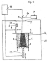
- the laser sintering device has an upwardly open frame 1 with a vertically movable platform 2 therein, which supports the three-dimensional object 3 to be produced.
- the frame 1 and the platform 2 define a space inside.
- the platform 2 is in connection with a lifting mechanism 12, which moves it in the vertical direction so that the respective layer of the object 3 to be consolidated lies in a working plane 4.
- a coater 5 for applying a layer of powdery building material 3a is provided.
- the build-up material 3a all laser-sinterable powders can be used, ie polymers such as polyamides, polystyrenes, metals, ceramics, composite materials and in particular high-temperature plastics such as PAEK (polyaryletherketones). Any metal and its alloys as well as mixtures with metallic components or with non-metallic components are suitable as the metal-containing powder material.
- the frame 1, the building material 3a is first supplied from a reservoir 6.
- the coater 5 is then moved at a predetermined height in the working plane 4, so that the layer of the powdery building material 3a lies with a defined height above the last solidified layer.
- the device further comprises a laser 7, which generates a laser beam 7a, which is focused by a deflector 8 to any points in the working plane 4.
- the laser beam 7a can selectively solidify the powdery building material 3a at the positions corresponding to the cross section of the object 3 to be manufactured.
- All lasers which are suitable for laser sintering or laser melting in each case for the corresponding building material can be used as the laser, eg CO 2 lasers, solid-state lasers, etc.
- the reference numeral 10 denotes a process chamber in which the frame 1, the platform 2, the lifting mechanism 12 and the coater 5 can be arranged.
- Reference numeral 9 denotes an opening in the process chamber 10 for introducing the laser beam 7a.
- a protective gas is introduced into the process chamber 10.
- a control unit 11 via which the apparatus is controlled in a coordinated manner for carrying out the building process.
- the laser sintering device is a micro-laser sintering device.
- the micro-laser sintering is characterized in that very fine powders are used and very thin layers are applied. This can achieve a resolution in the range of a few 10 microns or less.
- the powders used have particle sizes in the range from about 1 nm to about 100 nm. The particle size is determined by laser diffraction. DIN ISO 13320-1 measured.
- the layer thickness of the applied powder layers is about 1 micron to about 100 microns. In general, in micro-laser sintering, the grain diameter and the layer thickness are so large that the surface forces are higher than the gravitational forces.
- the beam diameter used is between about 1 micron to about 20 microns.
- As a laser it is preferable a fiber laser or a YAG laser used.
- all powders can be used from materials used in microtechnology, but especially metal powder.
- the platform 2 is moved by the lifting mechanism 12 in a first step until its upper side is a layer thickness below the working level 4. Then, by means of the storage container 6 and the coater 5, a first layer of the building material 3a is applied to the platform 2 and smoothed. Thereafter, the control unit 11 controls the deflector 8 so that the deflected laser beam 7a selectively impinges on the locations of the layer of the building material 3a which are to be solidified. As a result, the building material 3a is solidified or sintered at these locations, so that here the three-dimensional object 3 is formed.
- a next step the platform 2 is lowered by the lifting mechanism 12 by the thickness of the next layer.
- a second layer of building material is applied, smoothed and selectively solidified by means of the laser beam 7a.
- the laser 7 is actuated by the control unit 11 in two different operating modes.
- the first operating mode causes a first pulsed radiation 7a of the laser 7 at a first frequency.
- the second mode of operation causes a second radiation comprising a pulsed radiation having a higher frequency than the first pulsed radiation or a continuous radiation is.
- the frequency of the first pulsed radiation is for example between 60 kHz and 450 kHz, preferably about 60 kHz to 300 kHz.
- the frequency of the second pulsed radiation is for example between 200 and 450 kHz
- the pulsed laser radiation 7a can be generated by pulsed excitation or by measures in the laser 7 itself (Q-switching or mode coupling).
- the laser beam 7a is not emitted continuously as in a CW laser (continuous wave laser), but it is pulsed, i. broadcast in time-limited pulses.
- a laser 7 is used which can emit both a pulsed radiation 7a and a continuous radiation 7a.
- a CW laser is operated pulsed by the "pump power" in short cycles on and off.
- Carbon dioxide lasers can be pulsed to over 1 kHz.
- Another possibility is to generate the pulses by a combination of a CW laser and a modulator such.
- a first pulsed electromagnetic radiation 7a is irradiated to a first region of a layer of the building material 3a, and then a second pulsed radiation or a continuous electromagnetic radiation 7a is irradiated to a second region of the layer of the building material 3a.
- the first and second regions of the layer at least partially overlap.
- the areas may also overlap completely and may represent subregions of a layer or the entire layer.
- a time is provided between the emission of the first, pulsed electromagnetic radiation 7a onto the building material 3a and the emission of the second pulsed or continuous electromagnetic radiation 7a onto the building material 3a, in which the building material irradiated with the first, pulsed electromagnetic radiation 7a 3a solidifies.
- the combination of the first pulsed radiation and the second pulsed radiation or the continuous radiation 7a has a synergetic effect.
- the first, pulsed radiation 7a ensures the breaking up of the surface tensions of the powder particles in the building material 31 and the bonding of the powder grains.
- the second pulsed or continuous radiation 7a provides further densification of porous sintered structures in the building material 3a, which has already been irradiated with the first, pulsed electromagnetic radiation 7a. The second irradiation prevents the formation of molten beads.
- a first region of a layer can be irradiated with the first, pulsed radiation in temporal change, and subsequently a second region of the layer, which does not overlap the first region, can be irradiated with the second, continuous radiation.
- first and second areas which are pulsed or continuously irradiated and which completely, partially or not at all overlap, can be controlled and unified in an advantageous manner, the energy or heat input into the layer, so that stresses in the layer can be reduced.
- micro-LS micro-laser sintering
- the present invention is not only for the Laser sintering suitable, but also for Laser melting process and stereolithography process.
- particle radiation such as e.g. An electron beam can be used as electromagnetic radiation.
Landscapes
- Engineering & Computer Science (AREA)
- Chemical & Material Sciences (AREA)
- Materials Engineering (AREA)
- Physics & Mathematics (AREA)
- Manufacturing & Machinery (AREA)
- Optics & Photonics (AREA)
- Health & Medical Sciences (AREA)
- Toxicology (AREA)
- Plasma & Fusion (AREA)
- Mechanical Engineering (AREA)
- General Health & Medical Sciences (AREA)
- Powder Metallurgy (AREA)
Abstract
Description
- Die vorliegende Erfindung bezieht sich auf ein Verfahren und auf eine Vorrichtung zum Herstellen eines dreidimensionalen Objekts. Das hergestellte Objekt eignet sich insbesondere für den Einsatz in der Mikrotechnik.
-
EP-0 758 952 B1 beschreibt ein bekanntes Verfahren und eine bekannte Vorrichtung zum Herstellen eines dreidimensionalen Objekts, bei dem das Objekt durch aufeinanderfolgendes Verfestigen einzelner Schichten aus flüssigem oder pulverförmigem, verfestigbarem Baumaterial durch Einwirkung einer elektromagnetischen Strahlung erzeugt wird. Die elektromagnetische Strahlung ist hierbei vorzugsweise eine gepulste Laserstrahlung.DE 100 28 063 A1 undDE 100 65 960 A1 zeigen eine ähnliche Vorrichtung, wobei die elektromagnetische Strahlung eine gepulste Laserstrahlung ist. -
DE 102 58 934 A1 beschreibt ein Verfahren und eine Vorrichtung zum selektiven Verbinden von Körpern mit Trägern durch Laserstrahlen. Es wird gepulste Laserstrahlung eingesetzt und der Strahlungsdruck wird zum Verdichten und zum zusätzlichen Erwärmen der Pulverschicht verwendet. Es ist beschrieben, daß das Verfahren zur Erzeugung von Mikrostrukturen einsetzbar ist. Die durch das bekannte Verfahren erzeugbaren Teile, insbesondere Metallteile, besitzen jedoch ein Restporosität, weshalb sie für bestimmte Anwendungen in der Mikrotechnik nicht geeignet sind. - Es ist die Aufgabe der vorliegenden Erfindung, ein Verfahren und eine Vorrichtung zum Herstellen eines dreidimensionalen Objekts vorzusehen, durch das bzw. durch die Bauteile hergestellt werden können, die in der Mikrotechnik einsetzbar sind.
- Diese Aufgabe wird durch das Verfahren zum Herstellen eines dreidimensionalen Objekts mit den Merkmalen des Anspruchs 1 und durch die Vorrichtung zum Herstellen eines dreidimensionalen Objekts mit den Merkmalen des Anspruchs 15 gelöst. Vorteilhafte Weiterbildungen sind Gegenstand der Unteransprüche.
- Das erfindungsgemäße Verfahren und die entsprechende Vorrichtung sind in vorteilhafter Weise für das Mikro-Lasersintern (Mikro-LS) geeignet, bei dem dreidimensionale Objekte mit einer Auflösung im Mikrometerbereich aufgebaut werden.
- Bei dem erfindungsgemäßen Verfahren und der entsprechenden Vorrichtung können in vorteilhafter Weise dreidimensionale Bauteile mit erhöhter Dichte vorgesehen werden, wodurch die mechanischen Eigenschaften des Bauteils entsprechend verbessert werden.
- Weitere Merkmale und Zweckmäßigkeiten der Erfindung ergeben sich aus der Beschreibung von Ausführungsbeispielen anhand der beigefügten Zeichnung. Es zeigt:
-
Fig. 1 eine schematische Ansicht einer Vorrichtung zum Herstellen eines dreidimensionalen Objekts gemäß der vorliegenden Erfindung, die im Ausführungsbeispiel als Lasersintervorrichtung ausgebildet ist. - Die Lasersintervorrichtung weist einen nach oben hin offenen Rahmen 1 mit einer darin befindlichen, in vertikaler Richtung bewegbaren Plattform 2 auf, die das herzustellende dreidimensionale Objekt 3 trägt. Der Rahmen 1 und die Plattform 2 definieren im Inneren einen Bauraum. Die Plattform 2 ist mit einer Hubmechanik 12 in Verbindung, die sie in vertikaler Richtung so verfährt, dass die jeweils zu verfestigende Schicht des Objekts 3 in einer Arbeitsebene 4 liegt.
- Des Weiteren ist ein Beschichter 5 zum Aufbringen einer Schicht eines pulverförmigen Aufbaumaterials 3a vorgesehen. Als Aufbaumaterial 3a können alle lasersinterbaren Pulver verwendet werden, also Polymere wie z.B. Polyamide, Polystyrole, Metalle, Keramiken, Verbundmaterialien und insbesondere Hochtemperatur-Kunststoffe wie z.B. PAEK (Polyaryletherketone). Als metallhaltiges Pulvermaterial kommen beliebige Metalle und deren Legierungen sowie Mischungen mit metallischen Komponenten oder mit nichtmetallischen Komponenten in Frage. Dem Rahmen 1 wird zunächst das Aufbaumaterial 3a aus einem Vorratsbehälter 6 zugeführt. Der Beschichter 5 wird danach in einer vorbestimmten Höhe in der Arbeitsebene 4 verfahren, so dass die Schicht des pulverförmigen Aufbaumaterials 3a mit einer definierten Höhe über der zuletzt verfestigten Schicht liegt. Die Vorrichtung weist des Weiteren einen Laser 7 auf, der einen Laserstrahl 7a erzeugt, der durch eine Ablenkeinrichtung 8 auf beliebige Punkte in der Arbeitsebene 4 fokussiert wird. Dadurch kann der Laserstrahl 7a das pulverförmige Aufbaumaterial 3a an den Stellen selektiv verfestigen, die dem Querschnitt des herzustellenden Objekts 3 entsprechenden. Als Laser können alle Laser verwendet werden, die für das Lasersintern bzw. Laserschmelzen jeweils für das entsprechende Baumaterial geeignet sind, z.B. CO2 Laser, Festkörperlaser, etc.
- Mit dem Bezugszeichen 10 ist eine Prozesskammer bezeichnet, in der der Rahmen 1, die Plattform 2, die Hubmechanik 12 und der Beschichter 5 angeordnet werden können. Das Bezugszeichen 9 bezeichnet eine Öffnung in der Prozesskammer 10 zur Einleitung des Laserstrahls 7a. Vorzugsweise wird ein Schutzgas in die Prozesskammer 10 eingeführt. Es ist ferner eine Steuereinheit 11 vorgesehen, über die die Vorrichtung in koordinierter Weise zum Durchführen des Bauprozesses gesteuert wird.
- Vorzugsweise ist die Lasersintervorrichtung eine Mikro-Lasersintervorrichtung. Das Mikro-Lasersintern ist dadurch gekennzeichnet, daß sehr feine Pulver verwendet werden und sehr dünne Schichten aufgetragen werden. Damit lässt sich eine Auflösung im Bereich von einigen 10 µm oder weniger erreichen. Die verwendeten Pulver haben Korngrößen im Bereich von etwa 1 nm bis etwa 100 nm. Die Korngröße wird mit Laserbeugung gem. DIN ISO 13320-1 gemessen. Die Schichtdicke der aufgetragenen Pulverschichten beträgt etwa 1 µm bis etwa 100 µm. Allgemein ist beim Mikro-Lasersintern der Korndurchmesser und die Schichtdicke so groß, daß die Oberflächenkräfte höher als die Gravitationskräfte sind. Der verwendete Strahldurchmesser liegt zwischen etwa 1 µm bis etwa 20 µm. Als Laser wird vorzugsweise ein Faserlaser oder ein YAG-Laser eingesetzt. Als Pulver der bevorzugten Ausführung können alle Pulver aus Materialien verwendet werden, die in der Mikrotechnik Einsatz finden, insbesondere jedoch Metallpulver.
- Bei dem Betrieb der Vorrichtung wird in einem ersten Schritt die Plattform 2 durch die Hubmechanik 12 soweit verfahren, bis ihre obere Seite um eine Schichtdicke unterhalb der Arbeitsebene 4 liegt. Dann wird mittels des Vorratsbehälters 6 und des Beschichters 5 eine erste Schicht des Baumaterials 3a auf die Plattform 2 aufgebracht und geglättet. Daraufhin steuert die Steuereinheit 11 die Ablenkeinrichtung 8 derart, dass der abgelenkte Laserstrahl 7a selektiv an den Stellen der Schicht des Baumateriales 3a auftrifft, die verfestigt werden sollen. Dadurch wird an diesen Stellen das Baumaterial 3a verfestigt bzw. gesintert, so dass hier das dreidimensionale Objekt 3 entsteht.
- In einem nächsten Schritt wird die Plattform 2 durch die Hubmechanik 12 um die Dicke der nächsten Schicht abgesenkt. Durch den Vorratsbehälter 6 und den Beschichter 5 wird eine zweite Baumaterialschicht aufgetragen, geglättet und mittels des Laserstahls 7a selektiv verfestigt. Diese Schritte werden so oft durchgeführt, bis das gewünschte Objekt 3 hergestellt ist.
- Bei dem erfindungsgemäßen Verfahren und der erfindungsgemäßen Vorrichtung wird der Laser 7 durch die Steuereinheit 11 in zwei verschiedenen Betriebsmodi angesteuert. Der erste Betriebsmodus bewirkt eine erste gepulste Strahlung 7a des Lasers 7 mit einer ersten Frequenz. Der zweite Betriebsmodus bewirkt eine zweite Strahlung, die eine gepulste Strahlung mit einer höheren Frequenz als die erste gepulste Strahlung oder eine kontinuierliche Strahlung ist. Die Frequenz der ersten gepulsten Strahlung beträgt beispielsweise zwischen 60 kHz und 450 kHz vorzugsweise etwa 60 kHz bis 300 kHz. Die Frequenz der zweiten gepulsten Strahlung beträgt beispielsweise zwischen 200 und 450 kHz
- Die gepulste Laserstrahlung 7a kann durch gepulste Anregung oder auch durch Maßnahmen im Laser 7 selbst (Güteschaltung oder Modenkopplung) erzeugt werden. Bei der gepulsten Laserstrahlung wird der Laserstrahl 7a nicht kontinuierlich emittiert wie bei einem CW-Laser (Continuous Wave Laser bzw. Dauerstrichlaser), sondern er wird gepulst, d.h. in zeitlich begrenzten Pulsen ausgestrahlt.
- Vorzugsweise wird ein Laser 7 verwendet, der sowohl eine gepulste Strahlung 7a als auch eine kontinuierliche Strahlung 7a ausstrahlen kann. Hierbei wird ein CW-Laser gepulst betrieben, indem die "Pumpleistung" in kurzen Zyklen ein- und ausgeschaltet wird. Kohlendioxidlaser können so bis über 1 kHz gepulst betrieben werden. Eine weitere Möglichkeit ist eine Generierung der Pulse durch eine Kombination eines CW-Lasers und eines Modulators wie z. B. eines einfachen Choppers.
- Nachdem der Beschichter 5 die Schicht des Baumaterials 3a aufgetragen und geglättet hat, erfolgt die Bestrahlung der Schicht des Baumaterials 3a in zwei Schritten. Zuerst wird eine erste, gepulste elektromagnetische Strahlung 7a auf einen ersten Bereich einer Schicht des Baumaterials 3a ausgestrahlt, und anschließend wird eine zweite gepulste Strahlung oder eine kontinuierliche elektromagnetische Strahlung 7a auf einen zweiten Bereich der Schicht des Baumaterials 3a ausgestrahlt.
- Vorzugsweise überlappen sich der erste und der zweite Bereich der Schicht zumindest teilweise. Die Bereiche können sich auch ganz überlappen und können Teilbereiche einer Schicht oder die ganze Schicht darstellen. Weiter bevorzugt wird zwischen dem Ausstrahlen der ersten, gepulsten elektromagnetischen Strahlung 7a auf das Baumaterial 3a und dem Ausstrahlen der zweiten gepulsten oder kontinuierlichen elektromagnetischen Strahlung 7a auf das Baumaterial 3a eine Zeit vorgesehen, in der sich das mit der ersten, gepulsten elektromagnetischen Strahlung 7a bestrahlte Baumaterial 3a verfestigt.
- Die Kombination der ersten gepulsten Strahlung und der zweiten gepulsten Strahlung oder der kontinuierlichen Strahlung 7a hat eine synergetische Wirkung. Einerseits sorgt die erste, gepulste Strahlung 7a für das Aufbrechen der Oberflächenspannungen der Pulverpartikel im Baumaterial 31 und das Verbinden der Pulverkörner. Andererseits sorgt die zweite gepulste oder kontinuierliche Strahlung 7a für eine weitere Verdichtung von porösen Sinterstrukturen im Baumaterial 3a, das bereits mit der ersten, gepulsten elektromagnetischen Strahlung 7a bestrahlt wurde. Mit der zweiten Bestrahlung wird verhindert, daß sich Schmelzperlen bilden.
- In einer Abwandlung kann im zeitlichen Wechsel ein erster Bereich einer Schicht mit der ersten, gepulsten Strahlung bestrahlt werden, und anschließend kann ein zweiter Bereich der Schicht, der den ersten Bereich nicht überlappt, mit der zweiten, kontinuierlichen Strahlung bestrahlt werden. Es können eine Mehrzahl von ersten und zweiten Bereichen vorgesehen sein.
- Durch die Aufteilung der Schichten in erste und zweite Bereiche, die gepulst bzw. kontinuierlich bestrahlt werden und die sich ganz, teilweise oder überhaupt nicht überlappen, kann in vorteilhafter Weise der Energie- bzw. Wärmeeintrag in die Schicht gesteuert und vereinheitlicht werden, so dass Spannungen in der Schicht reduziert werden können.
- Das erfindungsgemäße Verfahren und die entsprechende Vorrichtung sind in vorteilhafter Weise für das Mikro-Lasersintern (Mikro-LS) geeignet, bei dem dreidimensionale Objekte mit Details im Mikrometerbereich aufgebaut werden.
- Der Schutzumfang beschränkt sich nicht auf die dargestellten Ausführungsbeispiele, sondern er umfasst weitere Änderungen und Abwandlungen, sofern diese innerhalb des durch die beigefügten Ansprüche definierten Umfangs fallen.
- Die vorliegende Erfindung ist nicht nur für das
Lasersinterverfahren geeignet, sondern auch für
Laserschmelzverfahren und Stereolithographieverfahren. - Anstelle der Laserstrahlung kann eine Teilchenstrahlung wie z.B. eine Elektronenstrahlung als elektromagnetische Strahlung verwendet werden.
- Anstelle eines einzigen Lasers können auch zwei
Laserlichtquellen verwendet werden.
Claims (17)
- Verfahren zum Herstellen eines dreidimensionalen Objekts (3), bei dem das Objekt (3) durch aufeinander folgendes Verfestigen einzelner Schichten aus flüssigem oder pulverförmigem, verfestigbarem Baumaterial (3a) durch Einwirkung einer elektromagnetischen Strahlung (7a) erzeugt wird, wobei innerhalb einer Schicht eine erste gepulste elektromagnetische Strahlung und eine zweite gepulste Strahlung mit einer höheren Frequenz als die erste gepulste Strahlung oder eine kontinuierliche elektromagnetische Strahlung verwendet werden.
- Verfahren nach Anspruch 1, mit den Schritten
Ausstrahlen einer ersten, gepulsten elektromagnetischen Strahlung (7a) auf einen ersten Bereich einer Schicht des Baumaterials (3a); und
Ausstrahlen einer zweiten gepulsten oder kontinuierlichen elektromagnetischen Strahlung (7a) auf einen zweiten Bereich der Schicht des Baumaterials (3a). - Verfahren gemäß Anspruch 1 oder 2,
wobei die erste Strahlung (7a) eine gepulste Laserstrahlung ist. - Verfahren gemäß einem der vorherigen Ansprüche,
wobei die Strahlung (7a) eine gepulste oder eine kontinuierliche Laserstrahlung ist. - Verfahren gemäß einem der Ansprüche 2 bis 4,
wobei sich der erste Bereich und der zweite Bereich der Schicht zumindest teilweise überlappen. - Verfahren gemäß einem der Ansprüche 1 bis 5,
wobei die Frequenz der ersten gepulsten Strahlung zwischen etwa 60 und etwa 300 kHz beträgt. - Verfahren nach einem der Ansprüche 1 bis 6, wobei die Frequenz der zweiten gepulsten Strahlung zwischen etwa 200 Und etwa 450 kHz beträgt.
- Verfahren gemäß einem der vorherigen Ansprüche,
wobei zwischen dem Ausstrahlen der ersten, gepulsten elektromagnetischen Strahlung (7a) auf das Baumaterial (3a) und dem Ausstrahlen der zweiten gepulsten oder kontinuierlichen elektromagnetischen Strahlung (7a) eine Zeit vorgesehen wird, in der sich das mit der ersten, gepulsten elektromagnetischen Strahlung (7a) bestrahlte Baumaterial (3a) verfestigt. - Verfahren gemäß einem der Ansprüche 1 bis 8, wobei innerhalb einer Schicht örtlich und/oder zeitlich ein Wechsel zwischen der ersten und der zweiten Strahlung vorgenommen wird.
- Verfahren nach einem der Ansprüche 1 bis 9, wobei ein Bereich einer Schicht, der mit der ersten gepulsten Strahlung bestrahlt worden ist, anschließend noch mit der zweiten gepulsten oder der kontinuierlichen Strahlung bestrahlt wird.
- Lasersinter- oder Laserschmelzverfahren als das Verfahren gemäß einem der vorherigen Ansprüche.
- Verfahren nach einem der Ansprüche 1 bis 11, wobei ein Pulver verwendet wird, das eine Korngröße zwischen etwa 1 nm und etwa 100 nm aufweist.
- Verfahren nach einem der Ansprüche 1 bis 12, wobei die Schichtdicke, in der das Pulver aufgetragen wird zwischen etwa 1 µm bis etwa 100 µm liegt.
- Verfahren nach einem der Ansprüche 1 bis 13, wobei der Strahldurchmesser zwischen 1 µm bis etwa 20 µm beträgt.
- Vorrichtung zum Herstellen eines dreidimensionalen Objekts (3), die das Verfahren gemäß einem der vorherigen Ansprüche durchführt.
- Vorrichtung gemäß Anspruch 15, die einen einzigen Laser (7) aufweist, der sowohl eine erste gepulste Laserstrahlung (7a) als auch eine zweite gepulste oder kontinuierliche Laserstrahlung (7a) ausstrahlen kann.
- Vorrichtung gemäß Anspruch 15, die einen ersten Laser, der eine gepulste Laserstrahlung ausstrahlt, und einen zweiten Laser aufweist, der eine gepulste oder eine kontinuierliche Laserstrahlung ausstrahlt.
Applications Claiming Priority (1)
| Application Number | Priority Date | Filing Date | Title |
|---|---|---|---|
| DE102010008960A DE102010008960A1 (de) | 2010-02-23 | 2010-02-23 | Verfahren und Vorrichtung zum Herstellen eines dreidimensionalen Objekts, das sich insbesondere für den Einsatz in der Mikrotechnik eignet |
Publications (2)
| Publication Number | Publication Date |
|---|---|
| EP2361751A1 true EP2361751A1 (de) | 2011-08-31 |
| EP2361751B1 EP2361751B1 (de) | 2012-12-19 |
Family
ID=43984108
Family Applications (1)
| Application Number | Title | Priority Date | Filing Date |
|---|---|---|---|
| EP11155584A Active EP2361751B1 (de) | 2010-02-23 | 2011-02-23 | Verfahren und Vorrichtung zum Herstellen eines dreidimensionalen Objekts, das sich insbesondere für den Einsatz in der Mikrotechnik eignet |
Country Status (4)
| Country | Link |
|---|---|
| US (2) | US8784720B2 (de) |
| EP (1) | EP2361751B1 (de) |
| JP (1) | JP2011173420A (de) |
| DE (1) | DE102010008960A1 (de) |
Cited By (3)
| Publication number | Priority date | Publication date | Assignee | Title |
|---|---|---|---|---|
| WO2014191257A1 (de) * | 2013-05-29 | 2014-12-04 | Osram Opto Semiconductors Gmbh | Anorganisches optisches element und verfahren zur herstellung eines anorganischen optischen elements |
| EP2782705B1 (de) | 2011-11-22 | 2017-09-13 | MTU Aero Engines GmbH | Verfahren zum generativen herstellen eines bauteils unter verwendung eines laserstrahles vor, während und nach dem verbinden |
| DE102017220153A1 (de) * | 2017-11-13 | 2019-06-19 | Trumpf Laser- Und Systemtechnik Gmbh | Verfahren und Vorrichtung zur schichtweisen additiven Fertigung von Bauteilen mittels eines kontinuierlichen und eines gepulsten Laserstrahls und zugehöriges Computerprogrammprodukt |
Families Citing this family (67)
| Publication number | Priority date | Publication date | Assignee | Title |
|---|---|---|---|---|
| CA2812758C (en) | 2010-09-27 | 2019-02-26 | Arkema Inc. | Heat treated polymer powders |
| DE102011079518A1 (de) * | 2011-07-21 | 2013-01-24 | Evonik Degussa Gmbh | Verbesserte Bauteileigenschaften durch optimierte Prozessführung im Laser-Sintern |
| US20140077422A1 (en) * | 2012-09-19 | 2014-03-20 | Pratt & Whitney Rocketdyne, Inc. | Reduced build mass additive manufacturing chamber |
| EP2737965A1 (de) * | 2012-12-01 | 2014-06-04 | Alstom Technology Ltd | Verfahren zur Herstellung einer metallischen Komponente mittels Zusatzlaserfertigung |
| WO2014125258A2 (en) | 2013-02-14 | 2014-08-21 | Renishaw Plc | Selective laser solidification apparatus and method |
| EP2969485B1 (de) | 2013-03-15 | 2019-06-05 | 3D Systems, Inc. | Rutsche für lasersinterungssysteme |
| US9669583B2 (en) | 2013-03-15 | 2017-06-06 | Renishaw Plc | Selective laser solidification apparatus and method |
| DE102013205724A1 (de) | 2013-03-28 | 2014-10-02 | Eos Gmbh Electro Optical Systems | Verfahren und Vorrichtung zum Herstellen eines dreidimensionalen Objekts |
| CN103273652B (zh) * | 2013-06-08 | 2015-12-09 | 王夏娃 | 数字光信号处理立体成型机及其立体成型方法 |
| CN103273653B (zh) * | 2013-06-18 | 2015-12-02 | 王夏娃 | 激光电镜立体成型机及立体成型方法 |
| DE102013011767A1 (de) * | 2013-07-10 | 2015-01-15 | Hochschule Mittweida (Fh) | Verwendung von kurzgepulster Laserstrahlung eines Lasers zum Verfestigen von Schichten aus nichtmetallischen Pulver |
| JP2015038237A (ja) * | 2013-08-19 | 2015-02-26 | 独立行政法人産業技術総合研究所 | 積層造形物、粉末積層造形装置及び粉末積層造形方法 |
| TWI535554B (zh) * | 2014-01-06 | 2016-06-01 | 財團法人工業技術研究院 | 立體成型物以及立體成型物的製造設備與製造方法 |
| WO2015145844A1 (ja) * | 2014-03-28 | 2015-10-01 | 株式会社日立製作所 | レーザ粉末積層造形装置及びレーザ粉末積層造形方法及び3次元積層造形装置 |
| GB2546016B (en) | 2014-06-20 | 2018-11-28 | Velo3D Inc | Apparatuses, systems and methods for three-dimensional printing |
| DE102015017470B4 (de) | 2014-08-22 | 2025-07-17 | Divergent Technologies, Inc. | Fehlererkennung für additive fertigungssysteme |
| WO2016081651A1 (en) | 2014-11-18 | 2016-05-26 | Sigma Labs, Inc. | Multi-sensor quality inference and control for additive manufacturing processes |
| US10226817B2 (en) | 2015-01-13 | 2019-03-12 | Sigma Labs, Inc. | Material qualification system and methodology |
| CN107428081B (zh) | 2015-01-13 | 2020-07-07 | 西格马实验室公司 | 材料鉴定系统和方法 |
| DE102015202964A1 (de) | 2015-02-18 | 2016-08-18 | Eos Gmbh Electro Optical Systems | Vorrichtung und Verfahren zum Herstellen eines dreidimensionalen Objekts |
| JP6494769B2 (ja) | 2015-04-30 | 2019-04-03 | ヒューレット−パッカード デベロップメント カンパニー エル.ピー.Hewlett‐Packard Development Company, L.P. | 3次元(3d)印刷 |
| WO2016173668A1 (en) | 2015-04-30 | 2016-11-03 | Hewlett-Packard Development Company, L.P. | Misalignment detection for a 3d printing device |
| US20180117845A1 (en) * | 2015-05-29 | 2018-05-03 | Velo3D, Inc. | Three-dimensional printing |
| CN107635749A (zh) | 2015-06-10 | 2018-01-26 | Ipg光子公司 | 多光束增材制造 |
| US10207489B2 (en) | 2015-09-30 | 2019-02-19 | Sigma Labs, Inc. | Systems and methods for additive manufacturing operations |
| US11691341B2 (en) | 2015-10-30 | 2023-07-04 | Seurat Technologies, Inc. | Part manipulation using printed manipulation points |
| JP2018535121A (ja) | 2015-11-06 | 2018-11-29 | ヴェロ・スリー・ディー・インコーポレイテッド | 熟達した3次元印刷 |
| US10207454B2 (en) | 2015-12-10 | 2019-02-19 | Velo3D, Inc. | Systems for three-dimensional printing |
| WO2017132664A1 (en) | 2016-01-28 | 2017-08-03 | Seurat Technologies, Inc. | Additive manufacturing, spatial heat treating system and method |
| EP3995277A1 (de) | 2016-01-29 | 2022-05-11 | Seurat Technologies, Inc. | System für generative fertigung |
| US20170239891A1 (en) | 2016-02-18 | 2017-08-24 | Velo3D, Inc. | Accurate three-dimensional printing |
| WO2018005439A1 (en) | 2016-06-29 | 2018-01-04 | Velo3D, Inc. | Three-dimensional printing and three-dimensional printers |
| US11691343B2 (en) | 2016-06-29 | 2023-07-04 | Velo3D, Inc. | Three-dimensional printing and three-dimensional printers |
| US10595990B2 (en) | 2016-09-06 | 2020-03-24 | Gyrus Acmi, Inc. | Osseointegrative adjustable ossicular prosthesis |
| US20180095450A1 (en) | 2016-09-30 | 2018-04-05 | Velo3D, Inc. | Three-dimensional objects and their formation |
| US10661341B2 (en) | 2016-11-07 | 2020-05-26 | Velo3D, Inc. | Gas flow in three-dimensional printing |
| US20180186080A1 (en) | 2017-01-05 | 2018-07-05 | Velo3D, Inc. | Optics in three-dimensional printing |
| EP3348385B1 (de) * | 2017-01-13 | 2024-08-07 | Airbus Operations GmbH | Verfahren und vorrichtung zur herstellung eines dreidimensionalen objekts durch generative schichtfertigung |
| WO2018160807A1 (en) | 2017-03-02 | 2018-09-07 | Velo3D, Inc. | Three-dimensional printing of three dimensional objects |
| US20180257300A1 (en) | 2017-03-09 | 2018-09-13 | Applied Materials, Inc. | Additive manufacturing with energy delivery system having rotating polygon and adjustment of angle of light path |
| US10449696B2 (en) | 2017-03-28 | 2019-10-22 | Velo3D, Inc. | Material manipulation in three-dimensional printing |
| WO2018209226A1 (en) | 2017-05-11 | 2018-11-15 | Seurat Technologies, Inc. | Solid state routing of patterned light for additive manufacturing optimization |
| JP7136811B2 (ja) | 2017-05-11 | 2022-09-13 | シューラット テクノロジーズ,インク. | 付加製造のためのパターン化された光の開閉所ビーム・ルーティング |
| US10981323B2 (en) | 2017-05-26 | 2021-04-20 | Applied Materials, Inc. | Energy delivery with rotating polygon and multiple light beams on same path for additive manufacturing |
| US10940641B2 (en) | 2017-05-26 | 2021-03-09 | Applied Materials, Inc. | Multi-light beam energy delivery with rotating polygon for additive manufacturing |
| US20180369914A1 (en) | 2017-06-23 | 2018-12-27 | Applied Materials, Inc. | Additive manufacturing with multiple polygon mirror scanners |
| US11135773B2 (en) | 2017-06-23 | 2021-10-05 | Applied Materials, Inc. | Additive manufacturing with multiple mirror scanners |
| DE102017120938A1 (de) * | 2017-09-11 | 2019-03-14 | Fraunhofer-Gesellschaft zur Förderung der angewandten Forschung e.V. | Verfahren zum Beschichten eines Substrats sowie Vorrichtung zur Durchführung des Verfahrens |
| DE102017126624A1 (de) * | 2017-11-13 | 2019-05-16 | Trumpf Laser- Und Systemtechnik Gmbh | Schichtselektive belichtung im überhangbereich bei der generativen fertigung |
| US11331855B2 (en) | 2017-11-13 | 2022-05-17 | Applied Materials, Inc. | Additive manufacturing with dithering scan path |
| US10272525B1 (en) | 2017-12-27 | 2019-04-30 | Velo3D, Inc. | Three-dimensional printing systems and methods of their use |
| US10144176B1 (en) | 2018-01-15 | 2018-12-04 | Velo3D, Inc. | Three-dimensional printing systems and methods of their use |
| JP2021523293A (ja) | 2018-05-09 | 2021-09-02 | アプライド マテリアルズ インコーポレイテッドApplied Materials,Incorporated | ポリゴンスキャナを用いた付加製造 |
| US11440099B2 (en) * | 2018-07-03 | 2022-09-13 | Purdue Research Foundation | Processes and systems for double-pulse laser micro sintering |
| WO2020045383A1 (ja) * | 2018-08-31 | 2020-03-05 | 国立大学法人大阪大学 | 金属積層造形装置及び金属積層造形方法 |
| CN113195127A (zh) | 2018-12-14 | 2021-07-30 | 速尔特技术有限公司 | 使用用于二维打印的高通量激光从粉末创建对象的增材制造系统 |
| WO2020132215A1 (en) | 2018-12-19 | 2020-06-25 | Seurat Technologies, Inc. | Additive manufacturing system using a pulse modulated laser for two-dimensional printing |
| CA3148849A1 (en) | 2019-07-26 | 2021-02-04 | Velo3D, Inc. | Quality assurance in formation of three-dimensional objects |
| DE102019218377A1 (de) * | 2019-11-27 | 2021-05-27 | Siemens Aktiengesellschaft | Verfahren zum selektiven Bestrahlen einer Pulverschicht in der additiven Herstellung mit einem ersten und einem zweiten Bestrahlungsmuster |
| EP3834963A1 (de) | 2019-12-09 | 2021-06-16 | Heraeus Additive Manufacturing GmbH | Additive fertigungsanlage, additives fertigungsverfahren und computerlesbares-speichermedium |
| GB201918601D0 (en) | 2019-12-17 | 2020-01-29 | Renishaw Plc | Powder bed fusion additive manufacturing methods and apparatus |
| US12162074B2 (en) * | 2020-11-25 | 2024-12-10 | Lawrence Livermore National Security, Llc | System and method for large-area pulsed laser melting of metallic powder in a laser powder bed fusion application |
| DE102021200994A1 (de) | 2021-02-03 | 2022-08-04 | Siemens Energy Global GmbH & Co. KG | Bestrahlungsstrategie für die additive Herstellung mit gepulster Bestrahlung |
| CA3209918A1 (en) * | 2021-03-01 | 2022-09-09 | Gunaranjan Chaudhry | Methods for laser calibration in additive manufacturing systems, and systems configured for same |
| WO2023023390A1 (en) | 2021-08-20 | 2023-02-23 | General Electric Company | Irradiation devices with optical modulators for additively manufacturing three-dimensional objects |
| US12030251B2 (en) | 2021-08-20 | 2024-07-09 | General Electric Company | Irradiation devices with optical modulators for additively manufacturing three-dimensional objects |
| US12558846B2 (en) | 2023-03-06 | 2026-02-24 | General Electric Company | Irradiation devices with optical modulators for additively manufacturing three-dimensional objects |
Citations (7)
| Publication number | Priority date | Publication date | Assignee | Title |
|---|---|---|---|---|
| US5597589A (en) * | 1986-10-17 | 1997-01-28 | Board Of Regents, The University Of Texas System | Apparatus for producing parts by selective sintering |
| EP0758952B1 (de) | 1994-05-13 | 1998-04-08 | EOS GmbH ELECTRO OPTICAL SYSTEMS | Verfahren und vorrichtung zum herstellen dreidimensionaler objekte |
| DE10065960A1 (de) | 2000-06-07 | 2001-12-20 | Bu St Gmbh Beratungsunternehme | Verfahren zur Herstellung eines Werkstückes mit exakter Geometrie |
| DE10028063A1 (de) | 2000-06-07 | 2002-01-17 | Bu St Gmbh Beratungsunternehme | Verfahren zur Herstellung eines Werkstückes mit exakter Geometrie |
| US20030074096A1 (en) * | 2001-10-15 | 2003-04-17 | Suman Das | Solid freeform fabrication of structurally engineered multifunctional devices |
| DE10258934A1 (de) | 2002-12-13 | 2004-07-22 | Laserinstitut Mittelsachsen E.V. | Verfahren und Vorrichtung zum selektiven Verbinden von Körpern mit Trägern mit Laserstrahlen und Verwendung eines Ultrakurzpulslasers zum selektiven Verbinden von Körpern mit Trägern |
| WO2007147221A1 (en) * | 2006-06-20 | 2007-12-27 | Katholieke Universiteit Leuven | Procedure and apparatus for in-situ monitoring and feedback control of selective laser powder processing |
Family Cites Families (18)
| Publication number | Priority date | Publication date | Assignee | Title |
|---|---|---|---|---|
| US3588440A (en) * | 1969-06-26 | 1971-06-28 | Hughes Aircraft Co | Laser combination energy system |
| US6001297A (en) * | 1997-04-28 | 1999-12-14 | 3D Systems, Inc. | Method for controlling exposure of a solidfiable medium using a pulsed radiation source in building a three-dimensional object using stereolithography |
| US5997795A (en) * | 1997-05-29 | 1999-12-07 | Rutgers, The State University | Processes for forming photonic bandgap structures |
| US7655586B1 (en) * | 2003-05-29 | 2010-02-02 | Pentron Ceramics, Inc. | Dental restorations using nanocrystalline materials and methods of manufacture |
| DE19953000C2 (de) * | 1999-11-04 | 2003-04-10 | Horst Exner | Verfahren und Einrichtung zur schnellen Herstellung von Körpern |
| US6500378B1 (en) * | 2000-07-13 | 2002-12-31 | Eom Technologies, L.L.C. | Method and apparatus for creating three-dimensional objects by cross-sectional lithography |
| US20040077745A1 (en) * | 2002-10-18 | 2004-04-22 | Jigeng Xu | Curable compositions and rapid prototyping process using the same |
| DE60300277T2 (de) * | 2002-11-08 | 2006-01-12 | Howmedica Osteonics Corp. | Lasererzeugte poröse Oberfläche |
| JP4384420B2 (ja) * | 2003-01-31 | 2009-12-16 | 株式会社メディアプラス | 積層造形方法 |
| DE102004012683A1 (de) * | 2004-03-16 | 2005-10-06 | Degussa Ag | Lasersintern mit Lasern mit einer Wellenlänge von 100 bis 3000 nm |
| JP4519560B2 (ja) * | 2004-07-30 | 2010-08-04 | 株式会社メディアプラス | 積層造形方法 |
| US7569174B2 (en) * | 2004-12-07 | 2009-08-04 | 3D Systems, Inc. | Controlled densification of fusible powders in laser sintering |
| US20080315461A1 (en) * | 2005-05-20 | 2008-12-25 | Huntsman Advanced Materials( Switzerland) Gmbh | Rapid Prototyping Apparatus and Method of Rapid Prototyping |
| JP4693681B2 (ja) * | 2006-03-31 | 2011-06-01 | パナソニック株式会社 | 光造形物の製造方法 |
| US20080029152A1 (en) * | 2006-08-04 | 2008-02-07 | Erel Milshtein | Laser scribing apparatus, systems, and methods |
| EP2379310B1 (de) * | 2008-12-22 | 2018-11-28 | Nederlandse Organisatie voor toegepast- natuurwetenschappelijk onderzoek TNO | Verfahren und vorrichtung zur schichtweisen herstellung eines dreidimensionalen objektes |
| US8777602B2 (en) * | 2008-12-22 | 2014-07-15 | Nederlandse Organisatie Voor Tobgepast-Natuurwetenschappelijk Onderzoek TNO | Method and apparatus for layerwise production of a 3D object |
| US8678805B2 (en) * | 2008-12-22 | 2014-03-25 | Dsm Ip Assets Bv | System and method for layerwise production of a tangible object |
-
2010
- 2010-02-23 DE DE102010008960A patent/DE102010008960A1/de not_active Ceased
-
2011
- 2011-02-22 US US13/032,283 patent/US8784720B2/en active Active
- 2011-02-23 EP EP11155584A patent/EP2361751B1/de active Active
- 2011-02-23 JP JP2011037063A patent/JP2011173420A/ja active Pending
-
2014
- 2014-06-17 US US14/306,988 patent/US20140356472A1/en not_active Abandoned
Patent Citations (8)
| Publication number | Priority date | Publication date | Assignee | Title |
|---|---|---|---|---|
| US5597589A (en) * | 1986-10-17 | 1997-01-28 | Board Of Regents, The University Of Texas System | Apparatus for producing parts by selective sintering |
| EP0758952B1 (de) | 1994-05-13 | 1998-04-08 | EOS GmbH ELECTRO OPTICAL SYSTEMS | Verfahren und vorrichtung zum herstellen dreidimensionaler objekte |
| US5753171A (en) * | 1994-05-13 | 1998-05-19 | Eos Gmbh Electro Optical Systems | Method and apparatus for producing a three-dimensional object |
| DE10065960A1 (de) | 2000-06-07 | 2001-12-20 | Bu St Gmbh Beratungsunternehme | Verfahren zur Herstellung eines Werkstückes mit exakter Geometrie |
| DE10028063A1 (de) | 2000-06-07 | 2002-01-17 | Bu St Gmbh Beratungsunternehme | Verfahren zur Herstellung eines Werkstückes mit exakter Geometrie |
| US20030074096A1 (en) * | 2001-10-15 | 2003-04-17 | Suman Das | Solid freeform fabrication of structurally engineered multifunctional devices |
| DE10258934A1 (de) | 2002-12-13 | 2004-07-22 | Laserinstitut Mittelsachsen E.V. | Verfahren und Vorrichtung zum selektiven Verbinden von Körpern mit Trägern mit Laserstrahlen und Verwendung eines Ultrakurzpulslasers zum selektiven Verbinden von Körpern mit Trägern |
| WO2007147221A1 (en) * | 2006-06-20 | 2007-12-27 | Katholieke Universiteit Leuven | Procedure and apparatus for in-situ monitoring and feedback control of selective laser powder processing |
Non-Patent Citations (1)
| Title |
|---|
| P. REGENFUSS, L. HARTWIG, S. KLÖTZER, R. EBERT, TH. BRABANT, T. PETSCH, H. EXNER: "Industrial freeform generation of microtools by laser micro sintering", RAPID PROTOTYPING JOURNAL, vol. 11, no. 1, 1995, pages 1 - 15, XP002638095, Retrieved from the Internet <URL:http://www.emeraldinsight.com/journals.htm?issn=1355-2546&volume=11&issue=1&articleid=1464529&show=html> [retrieved on 20110519] * |
Cited By (3)
| Publication number | Priority date | Publication date | Assignee | Title |
|---|---|---|---|---|
| EP2782705B1 (de) | 2011-11-22 | 2017-09-13 | MTU Aero Engines GmbH | Verfahren zum generativen herstellen eines bauteils unter verwendung eines laserstrahles vor, während und nach dem verbinden |
| WO2014191257A1 (de) * | 2013-05-29 | 2014-12-04 | Osram Opto Semiconductors Gmbh | Anorganisches optisches element und verfahren zur herstellung eines anorganischen optischen elements |
| DE102017220153A1 (de) * | 2017-11-13 | 2019-06-19 | Trumpf Laser- Und Systemtechnik Gmbh | Verfahren und Vorrichtung zur schichtweisen additiven Fertigung von Bauteilen mittels eines kontinuierlichen und eines gepulsten Laserstrahls und zugehöriges Computerprogrammprodukt |
Also Published As
| Publication number | Publication date |
|---|---|
| US20140356472A1 (en) | 2014-12-04 |
| DE102010008960A1 (de) | 2011-08-25 |
| EP2361751B1 (de) | 2012-12-19 |
| US8784720B2 (en) | 2014-07-22 |
| US20110221099A1 (en) | 2011-09-15 |
| JP2011173420A (ja) | 2011-09-08 |
Similar Documents
| Publication | Publication Date | Title |
|---|---|---|
| EP2361751B1 (de) | Verfahren und Vorrichtung zum Herstellen eines dreidimensionalen Objekts, das sich insbesondere für den Einsatz in der Mikrotechnik eignet | |
| DE19953000C2 (de) | Verfahren und Einrichtung zur schnellen Herstellung von Körpern | |
| EP2275247B1 (de) | Vorrichtung und Verfahren zum Herstellen von dreidimensionalen Objekten mittels eines generativen Fertigungsverfahrens | |
| DE102016208196B4 (de) | Verfahren zur generativen Herstellung von dreidimensionalen Verbundbauteilen | |
| EP2386405B1 (de) | Vorrichtung zum generativen Herstellen eines dreidimensionalen Objekts mit Baufeldbegrenzung | |
| DE102016211952A1 (de) | Beschichtungseinheit, Beschichtungsverfahren, Vorrichtung und Verfahren zum generativen Herstellen eines dreidimensionalen Objekts | |
| DE102016211949A1 (de) | Beschichtungseinheit, Beschichtungsverfahren, Vorrichtung und Verfahren zum generativen Herstellen eines dreidimensionalen Objekts | |
| DE102014201818A1 (de) | Verfahren und Vorrichtung zur verbesserten Steuerung des Energieeintrags in einem generativen Schichtbauverfahren | |
| DE102016209933A1 (de) | Vorrichtung und Verfahren zum generativen Herstellen eines dreidimensionalen Objekts | |
| EP2794152A1 (de) | Verfahren zur fertigung eines kompakten bauteils sowie mit dem verfahren herstellbares bauteil | |
| EP3718729A1 (de) | Fertigungsverfahren mit additiver bauteilherstellung und nachbearbeitung | |
| DE102016204905A1 (de) | Verfahren und Vorrichtung zum Herstellen eines dreidimensionalen Objekts | |
| DE102010029078A1 (de) | Verfahren zur Herstellung eines Gegenstandes durch schichtweises Aufbauen aus pulverförmigem Werkstoff | |
| DE102009051552A1 (de) | Verfahren und Vorrichtung zur Herstellung eines Bauteils | |
| DE102013224693A1 (de) | Verfahren zur beschleunigten Herstellung von Objekten mittels generativer Fertigung | |
| WO2017153187A1 (de) | Generatives schichtbauverfahren mit verbesserter detailauflösung und vorrichtung zur durchführung desselben | |
| WO2017081293A1 (de) | Verfahren und vorrichtung zum herstellen eines dreidimensionalen objekts | |
| EP3331687A1 (de) | Verfahren und vorrichtung zum herstellen eines dreidimensionalen objekts | |
| DE4439124C2 (de) | Verfahren und Vorrichtung zum Herstellen eines dreidimensionalen Objektes | |
| DE102004022386B4 (de) | Vorrichtung zur Herstellung von Mikrokörpern | |
| EP4313453A1 (de) | Vorrichtung zur additiven fertigung von fertigungsprodukten | |
| EP3015198A1 (de) | Vorrichtung und Verfahren zur generativen Herstellung zumindest eines Bauteilbereichs eines Bauteils | |
| WO2024146672A1 (de) | Verfahren und vorrichtung zur herstellung von mikrobauteilen und mikrokomponenten durch additive fertigung mittels mikro laser sintern | |
| DE10258934B4 (de) | Verfahren zur Herstellung eines Formkörpers und Verwendung eines Ultrakurzpulslasers zur Herstellung eines Formkörpers | |
| DE202004007213U1 (de) | Vorrichtung zur Herstellung von Mikrokörpern |
Legal Events
| Date | Code | Title | Description |
|---|---|---|---|
| PUAI | Public reference made under article 153(3) epc to a published international application that has entered the european phase |
Free format text: ORIGINAL CODE: 0009012 |
|
| AK | Designated contracting states |
Kind code of ref document: A1 Designated state(s): AL AT BE BG CH CY CZ DE DK EE ES FI FR GB GR HR HU IE IS IT LI LT LU LV MC MK MT NL NO PL PT RO RS SE SI SK SM TR |
|
| AX | Request for extension of the european patent |
Extension state: BA ME |
|
| 17P | Request for examination filed |
Effective date: 20111207 |
|
| 17Q | First examination report despatched |
Effective date: 20120201 |
|
| GRAP | Despatch of communication of intention to grant a patent |
Free format text: ORIGINAL CODE: EPIDOSNIGR1 |
|
| GRAS | Grant fee paid |
Free format text: ORIGINAL CODE: EPIDOSNIGR3 |
|
| GRAA | (expected) grant |
Free format text: ORIGINAL CODE: 0009210 |
|
| AK | Designated contracting states |
Kind code of ref document: B1 Designated state(s): AL AT BE BG CH CY CZ DE DK EE ES FI FR GB GR HR HU IE IS IT LI LT LU LV MC MK MT NL NO PL PT RO RS SE SI SK SM TR |
|
| REG | Reference to a national code |
Ref country code: GB Ref legal event code: FG4D Free format text: NOT ENGLISH |
|
| REG | Reference to a national code |
Ref country code: CH Ref legal event code: EP |
|
| REG | Reference to a national code |
Ref country code: AT Ref legal event code: REF Ref document number: 589137 Country of ref document: AT Kind code of ref document: T Effective date: 20130115 |
|
| REG | Reference to a national code |
Ref country code: DE Ref legal event code: R096 Ref document number: 502011000293 Country of ref document: DE Effective date: 20130207 |
|
| REG | Reference to a national code |
Ref country code: SE Ref legal event code: TRGR |
|
| PG25 | Lapsed in a contracting state [announced via postgrant information from national office to epo] |
Ref country code: ES Free format text: LAPSE BECAUSE OF FAILURE TO SUBMIT A TRANSLATION OF THE DESCRIPTION OR TO PAY THE FEE WITHIN THE PRESCRIBED TIME-LIMIT Effective date: 20130330 Ref country code: LT Free format text: LAPSE BECAUSE OF FAILURE TO SUBMIT A TRANSLATION OF THE DESCRIPTION OR TO PAY THE FEE WITHIN THE PRESCRIBED TIME-LIMIT Effective date: 20121219 Ref country code: NO Free format text: LAPSE BECAUSE OF FAILURE TO SUBMIT A TRANSLATION OF THE DESCRIPTION OR TO PAY THE FEE WITHIN THE PRESCRIBED TIME-LIMIT Effective date: 20130319 Ref country code: FI Free format text: LAPSE BECAUSE OF FAILURE TO SUBMIT A TRANSLATION OF THE DESCRIPTION OR TO PAY THE FEE WITHIN THE PRESCRIBED TIME-LIMIT Effective date: 20121219 |
|
| REG | Reference to a national code |
Ref country code: NL Ref legal event code: T3 |
|
| REG | Reference to a national code |
Ref country code: LT Ref legal event code: MG4D |
|
| PG25 | Lapsed in a contracting state [announced via postgrant information from national office to epo] |
Ref country code: SI Free format text: LAPSE BECAUSE OF FAILURE TO SUBMIT A TRANSLATION OF THE DESCRIPTION OR TO PAY THE FEE WITHIN THE PRESCRIBED TIME-LIMIT Effective date: 20121219 Ref country code: GR Free format text: LAPSE BECAUSE OF FAILURE TO SUBMIT A TRANSLATION OF THE DESCRIPTION OR TO PAY THE FEE WITHIN THE PRESCRIBED TIME-LIMIT Effective date: 20130320 Ref country code: LV Free format text: LAPSE BECAUSE OF FAILURE TO SUBMIT A TRANSLATION OF THE DESCRIPTION OR TO PAY THE FEE WITHIN THE PRESCRIBED TIME-LIMIT Effective date: 20121219 |
|
| PG25 | Lapsed in a contracting state [announced via postgrant information from national office to epo] |
Ref country code: SK Free format text: LAPSE BECAUSE OF FAILURE TO SUBMIT A TRANSLATION OF THE DESCRIPTION OR TO PAY THE FEE WITHIN THE PRESCRIBED TIME-LIMIT Effective date: 20121219 Ref country code: EE Free format text: LAPSE BECAUSE OF FAILURE TO SUBMIT A TRANSLATION OF THE DESCRIPTION OR TO PAY THE FEE WITHIN THE PRESCRIBED TIME-LIMIT Effective date: 20121219 Ref country code: RS Free format text: LAPSE BECAUSE OF FAILURE TO SUBMIT A TRANSLATION OF THE DESCRIPTION OR TO PAY THE FEE WITHIN THE PRESCRIBED TIME-LIMIT Effective date: 20121219 Ref country code: CZ Free format text: LAPSE BECAUSE OF FAILURE TO SUBMIT A TRANSLATION OF THE DESCRIPTION OR TO PAY THE FEE WITHIN THE PRESCRIBED TIME-LIMIT Effective date: 20121219 Ref country code: BG Free format text: LAPSE BECAUSE OF FAILURE TO SUBMIT A TRANSLATION OF THE DESCRIPTION OR TO PAY THE FEE WITHIN THE PRESCRIBED TIME-LIMIT Effective date: 20130319 Ref country code: IS Free format text: LAPSE BECAUSE OF FAILURE TO SUBMIT A TRANSLATION OF THE DESCRIPTION OR TO PAY THE FEE WITHIN THE PRESCRIBED TIME-LIMIT Effective date: 20130419 |
|
| PG25 | Lapsed in a contracting state [announced via postgrant information from national office to epo] |
Ref country code: PL Free format text: LAPSE BECAUSE OF FAILURE TO SUBMIT A TRANSLATION OF THE DESCRIPTION OR TO PAY THE FEE WITHIN THE PRESCRIBED TIME-LIMIT Effective date: 20121219 Ref country code: PT Free format text: LAPSE BECAUSE OF FAILURE TO SUBMIT A TRANSLATION OF THE DESCRIPTION OR TO PAY THE FEE WITHIN THE PRESCRIBED TIME-LIMIT Effective date: 20130419 Ref country code: RO Free format text: LAPSE BECAUSE OF FAILURE TO SUBMIT A TRANSLATION OF THE DESCRIPTION OR TO PAY THE FEE WITHIN THE PRESCRIBED TIME-LIMIT Effective date: 20121219 |
|
| PG25 | Lapsed in a contracting state [announced via postgrant information from national office to epo] |
Ref country code: MC Free format text: LAPSE BECAUSE OF NON-PAYMENT OF DUE FEES Effective date: 20130228 |
|
| PLBE | No opposition filed within time limit |
Free format text: ORIGINAL CODE: 0009261 |
|
| STAA | Information on the status of an ep patent application or granted ep patent |
Free format text: STATUS: NO OPPOSITION FILED WITHIN TIME LIMIT |
|
| PG25 | Lapsed in a contracting state [announced via postgrant information from national office to epo] |
Ref country code: DK Free format text: LAPSE BECAUSE OF FAILURE TO SUBMIT A TRANSLATION OF THE DESCRIPTION OR TO PAY THE FEE WITHIN THE PRESCRIBED TIME-LIMIT Effective date: 20121219 |
|
| 26N | No opposition filed |
Effective date: 20130920 |
|
| PG25 | Lapsed in a contracting state [announced via postgrant information from national office to epo] |
Ref country code: CY Free format text: LAPSE BECAUSE OF FAILURE TO SUBMIT A TRANSLATION OF THE DESCRIPTION OR TO PAY THE FEE WITHIN THE PRESCRIBED TIME-LIMIT Effective date: 20121219 Ref country code: HR Free format text: LAPSE BECAUSE OF FAILURE TO SUBMIT A TRANSLATION OF THE DESCRIPTION OR TO PAY THE FEE WITHIN THE PRESCRIBED TIME-LIMIT Effective date: 20121219 |
|
| REG | Reference to a national code |
Ref country code: IE Ref legal event code: MM4A |
|
| REG | Reference to a national code |
Ref country code: DE Ref legal event code: R097 Ref document number: 502011000293 Country of ref document: DE Effective date: 20130920 |
|
| PG25 | Lapsed in a contracting state [announced via postgrant information from national office to epo] |
Ref country code: AL Free format text: LAPSE BECAUSE OF FAILURE TO SUBMIT A TRANSLATION OF THE DESCRIPTION OR TO PAY THE FEE WITHIN THE PRESCRIBED TIME-LIMIT Effective date: 20121219 Ref country code: IE Free format text: LAPSE BECAUSE OF NON-PAYMENT OF DUE FEES Effective date: 20130223 |
|
| PGFP | Annual fee paid to national office [announced via postgrant information from national office to epo] |
Ref country code: SE Payment date: 20140218 Year of fee payment: 4 Ref country code: CH Payment date: 20140218 Year of fee payment: 4 Ref country code: NL Payment date: 20140218 Year of fee payment: 4 |
|
| PGFP | Annual fee paid to national office [announced via postgrant information from national office to epo] |
Ref country code: BE Payment date: 20140218 Year of fee payment: 4 |
|
| PG25 | Lapsed in a contracting state [announced via postgrant information from national office to epo] |
Ref country code: MT Free format text: LAPSE BECAUSE OF FAILURE TO SUBMIT A TRANSLATION OF THE DESCRIPTION OR TO PAY THE FEE WITHIN THE PRESCRIBED TIME-LIMIT Effective date: 20121219 |
|
| PG25 | Lapsed in a contracting state [announced via postgrant information from national office to epo] |
Ref country code: SM Free format text: LAPSE BECAUSE OF FAILURE TO SUBMIT A TRANSLATION OF THE DESCRIPTION OR TO PAY THE FEE WITHIN THE PRESCRIBED TIME-LIMIT Effective date: 20121219 |
|
| PG25 | Lapsed in a contracting state [announced via postgrant information from national office to epo] |
Ref country code: BE Free format text: LAPSE BECAUSE OF NON-PAYMENT OF DUE FEES Effective date: 20150228 Ref country code: TR Free format text: LAPSE BECAUSE OF FAILURE TO SUBMIT A TRANSLATION OF THE DESCRIPTION OR TO PAY THE FEE WITHIN THE PRESCRIBED TIME-LIMIT Effective date: 20121219 |
|
| PG25 | Lapsed in a contracting state [announced via postgrant information from national office to epo] |
Ref country code: LU Free format text: LAPSE BECAUSE OF NON-PAYMENT OF DUE FEES Effective date: 20130223 Ref country code: MK Free format text: LAPSE BECAUSE OF FAILURE TO SUBMIT A TRANSLATION OF THE DESCRIPTION OR TO PAY THE FEE WITHIN THE PRESCRIBED TIME-LIMIT Effective date: 20121219 Ref country code: HU Free format text: LAPSE BECAUSE OF FAILURE TO SUBMIT A TRANSLATION OF THE DESCRIPTION OR TO PAY THE FEE WITHIN THE PRESCRIBED TIME-LIMIT; INVALID AB INITIO Effective date: 20110223 |
|
| REG | Reference to a national code |
Ref country code: NL Ref legal event code: V1 Effective date: 20150901 |
|
| REG | Reference to a national code |
Ref country code: SE Ref legal event code: EUG |
|
| PG25 | Lapsed in a contracting state [announced via postgrant information from national office to epo] |
Ref country code: NL Free format text: LAPSE BECAUSE OF NON-PAYMENT OF DUE FEES Effective date: 20150901 |
|
| REG | Reference to a national code |
Ref country code: CH Ref legal event code: PL |
|
| PG25 | Lapsed in a contracting state [announced via postgrant information from national office to epo] |
Ref country code: LI Free format text: LAPSE BECAUSE OF NON-PAYMENT OF DUE FEES Effective date: 20150228 Ref country code: CH Free format text: LAPSE BECAUSE OF NON-PAYMENT OF DUE FEES Effective date: 20150228 |
|
| PG25 | Lapsed in a contracting state [announced via postgrant information from national office to epo] |
Ref country code: SE Free format text: LAPSE BECAUSE OF NON-PAYMENT OF DUE FEES Effective date: 20150224 |
|
| REG | Reference to a national code |
Ref country code: FR Ref legal event code: PLFP Year of fee payment: 6 |
|
| REG | Reference to a national code |
Ref country code: DE Ref legal event code: R079 Ref document number: 502011000293 Country of ref document: DE Free format text: PREVIOUS MAIN CLASS: B29C0067000000 Ipc: B29C0064106000 |
|
| REG | Reference to a national code |
Ref country code: FR Ref legal event code: PLFP Year of fee payment: 7 |
|
| REG | Reference to a national code |
Ref country code: AT Ref legal event code: MM01 Ref document number: 589137 Country of ref document: AT Kind code of ref document: T Effective date: 20160223 |
|
| PG25 | Lapsed in a contracting state [announced via postgrant information from national office to epo] |
Ref country code: AT Free format text: LAPSE BECAUSE OF NON-PAYMENT OF DUE FEES Effective date: 20160223 |
|
| REG | Reference to a national code |
Ref country code: FR Ref legal event code: PLFP Year of fee payment: 8 |
|
| P01 | Opt-out of the competence of the unified patent court (upc) registered |
Effective date: 20230525 |
|
| PGFP | Annual fee paid to national office [announced via postgrant information from national office to epo] |
Ref country code: DE Payment date: 20250218 Year of fee payment: 15 |
|
| PGFP | Annual fee paid to national office [announced via postgrant information from national office to epo] |
Ref country code: FR Payment date: 20250221 Year of fee payment: 15 |
|
| PGFP | Annual fee paid to national office [announced via postgrant information from national office to epo] |
Ref country code: IT Payment date: 20250224 Year of fee payment: 15 Ref country code: GB Payment date: 20250219 Year of fee payment: 15 |