EP2361733A2 - Storage device for bits with a ratchet held in the narrow side of a housing - Google Patents
Storage device for bits with a ratchet held in the narrow side of a housing Download PDFInfo
- Publication number
- EP2361733A2 EP2361733A2 EP11154958A EP11154958A EP2361733A2 EP 2361733 A2 EP2361733 A2 EP 2361733A2 EP 11154958 A EP11154958 A EP 11154958A EP 11154958 A EP11154958 A EP 11154958A EP 2361733 A2 EP2361733 A2 EP 2361733A2
- Authority
- EP
- European Patent Office
- Prior art keywords
- tool
- storage device
- receiving opening
- housing
- narrow side
- Prior art date
- Legal status (The legal status is an assumption and is not a legal conclusion. Google has not performed a legal analysis and makes no representation as to the accuracy of the status listed.)
- Granted
Links
Images


Classifications
-
- B—PERFORMING OPERATIONS; TRANSPORTING
- B25—HAND TOOLS; PORTABLE POWER-DRIVEN TOOLS; MANIPULATORS
- B25H—WORKSHOP EQUIPMENT, e.g. FOR MARKING-OUT WORK; STORAGE MEANS FOR WORKSHOPS
- B25H3/00—Storage means or arrangements for workshops facilitating access to, or handling of, work tools or instruments
- B25H3/003—Holders for drill bits or the like
-
- B—PERFORMING OPERATIONS; TRANSPORTING
- B25—HAND TOOLS; PORTABLE POWER-DRIVEN TOOLS; MANIPULATORS
- B25B—TOOLS OR BENCH DEVICES NOT OTHERWISE PROVIDED FOR, FOR FASTENING, CONNECTING, DISENGAGING OR HOLDING
- B25B13/00—Spanners; Wrenches
- B25B13/46—Spanners; Wrenches of the ratchet type, for providing a free return stroke of the handle
- B25B13/461—Spanners; Wrenches of the ratchet type, for providing a free return stroke of the handle with concentric driving and driven member
-
- B—PERFORMING OPERATIONS; TRANSPORTING
- B25—HAND TOOLS; PORTABLE POWER-DRIVEN TOOLS; MANIPULATORS
- B25F—COMBINATION OR MULTI-PURPOSE TOOLS NOT OTHERWISE PROVIDED FOR; DETAILS OR COMPONENTS OF PORTABLE POWER-DRIVEN TOOLS NOT PARTICULARLY RELATED TO THE OPERATIONS PERFORMED AND NOT OTHERWISE PROVIDED FOR
- B25F1/00—Combination or multi-purpose hand tools
- B25F1/02—Combination or multi-purpose hand tools with interchangeable or adjustable tool elements
Definitions
- the invention relates to a storage device with in one, narrow sides and broad sides having housing which stores in a rotary drive tool insertable tool inserts, in particular in the form of sortenburnerbits.
- the invention relates to a storage device with in a narrow sides and broad sides having housing which stores in a rotary drive tool insertable tool inserts, in particular in the form of SSenburnerbits and which at least one of the shutter sides and at least one part of one of the broad sides forming frame part and in a recess of the frame part in a closed position has received pivoting part which is pivotable about a pivot axis from the closed position to an open position in which the not removable in the closed position tool inserts are removed, and with an in one of the narrow sides associated tool receiving openings held additional tool.
- a generic storage device is in the DE 10 2006 055 025 A1 described.
- the storage device described therein serves to store bits, nuts and a screwdriver handle with a chuck into which the hexagonal sections of the bits can be inserted.
- the screwing tool and the bits are carried by a pivoting part, which is pivotally supported on a frame part.
- the tool inserts are in insertion openings.
- the frame forms two mutually parallel frame legs, whose free ends form a pivot bearing, through which the pivot axis extends, to which the pivoting part relative to the Frame part is pivotable.
- In a narrow wall of the frame part, which extends transversely to the pivot axis direction there is a circular opening into which an extension shaft is inserted in the axial direction. In the transverse narrow side there are viewing windows through which the extension shaft is visible.
- the DE 10 2006 055 195 A1 also describes a bit storage device in which the pivot member additionally carries a pivot bar so that two rows of bits can be juxtaposed.
- the US 7,530,459 B2 describes a storage device for tool inserts, in which the pivoting part is designed as a housing cover. Here are the tools in the frame part.
- the invention has the object of developing the generic storage device nutzsvorteilhaft the task.
- a tool receiving opening is located in a narrow side of the housing.
- the ratchet has a drive head with a freewheel mechanism, which has an output opening.
- the output opening has a polygonal profile, which is adapted to the polygonal drive profile of the tool inserts.
- the ratchet is located in the tool receiving opening such that the insertion opening is accessible to insert therein a tool insert.
- the ratchet is positively in a recess and is of a holding member in the recess held.
- the preferably arranged near a housing corner head of the ratchet has a diameter which corresponds at most to the width of the narrow side, so that the plane of rotation of the Freilaufgesperres the ratchet is located approximately in the narrow side plane.
- the ratchet arm extends in the extension direction of the housing narrow side, so that an optimal torque transmission is given when the housing is used as a handle. Since the broad side surface of the ratchet lies in the narrow side plane of the housing, a switch of whilsgesperres in the storage position of the ratchet is accessible. It is particularly beneficial if the holding member, with which the ratchet is tied to the housing, only attacks the ratchet arm.
- the tool receiving opening is elongate and located in a narrow side which runs parallel to the pivot axis. This is the longer narrow side, whereas the shorter narrow side is transverse to the Schenkachsenraum.
- the additional tool can be designed as a ratchet, which preferably has a hexagonal output opening into which the drive hexagonal sections of the tool inserts can be inserted.
- a holding member is provided for holding the additional tool, so preferably the ratchet, in the tool receiving opening.
- This can assume a holding position, in which the ratchet, although visible, can not be removed from the tool receiving opening. It can be moved to a release position in which the ratchet of the tool receiving opening can be removed.
- the holding member is formed by a slider which is guided parallel to the direction of the pivot axis.
- the two facing away from each other wide sides of the housing and in particular the broad side sections, which are formed by the frame part, can at their for Narrow side facing edge have a guide in which the slider is guided.
- these guides are formed by grooves, can engage in the guide projections of the slider.
- the holding member which surrounds the arm of the ratchet area may be arcuate in design and preferably be designed in cross-section C-shaped.
- a middle arch section overhangs a section of the ratchet.
- the two bow ends form guide protrusions facing each other, which can engage in the guide grooves.
- the tool receiving opening may be provided on one of the two longer narrow sides. But it is also possible that both a tool receiving opening of the narrow side of the frame part, as well as a tool receiving opening of the narrow side of the pivoting part is assigned.
- a complete narrow side of the frame part and the vast majority of the other narrow side of the pivot part is formed, which extends only between the frame legs of the frame part.
- nuts are arranged with which hex nuts or hexagonal screw heads can be rotated.
- the nuts have a hexagon socket cross section for this purpose.
- the nuts can be arranged in the axial direction one behind the other or in an axially parallel arrangement in the tool receiving opening.
- the relevant tool receiving opening preferably extends in the region of the axis of rotation. It is then assigned to the swivel part.
- the edge of the tool holder in which in particular a head, a neck and an arm having ratchet, which is adapted to the outline contour of the additional tool.
- the arm of the gun may have a thickened peripheral portion.
- the bulge thus formed forms a latching projection, which in a latching niche of the holding member, in particular the engages trained by the holding member slider.
- the detent niche is preferably located in the inner arch portion of the slider.
- the narrow side, which forms the tool receiving opening, is preferably rounded. As a result, the edge of the tool receiving aperture extends along a contour line which clears troughs which allow the tool to be removed as finger engagement apertures.
- the exemplary embodiments relate to bit storage housings which form a narrow side 5 in which a ratchet 11 lies in a tool receiving opening.
- the hexagonal portion 4 'of a bit can be used, so that the housing 1, 2 can be used as a handle.
- the tool receiving opening 10 is arranged so that the head 13 of the ratchet 11 is located in the corner region of two abutting narrow sides. Since the narrow side 5, in which the tool receiving opening 10 is located, is longer than the longitudinal extent of the entire ratchet 11, the housing also forms a lever extension.
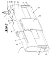
- the equipped with a bit, in the housing housing inserting tool shows the FIG. 2 ,
- the gun is here opposite the representation in Fig. 1 turned by 180 °, so that the knurled, the hexagonal output opening 12 surrounding ring rests on the bottom 23 of the tool receiving opening 10.
- the knurled ring has a circular inner opening, at which the end of the hexagonal portion 4 'of the bit 4 can be supported.
- it is a storage device, which consists of two substantially manufactured by injection molding plastic housing parts, namely a frame part 1, which forms two spaced apart and mutually parallel frame legs 1 '.
- the frame legs 1 ' form two narrow sides of the housing and are connected to one another via a housing web, which forms a longer, rounded narrow side 5.
- the second housing part is a between the frame legs 1 'arranged pivoting part 2, which is about a pivot axis 9 of a in the Fig. 1 shown closed position in a in the Fig. 8 shown open position is pivotable.
- the pivoting part 2 forms one of the first narrow side 5 opposite second narrow side 6, which is also rounded.
- the pivot axis 9 passes through the free ends of the frame legs 1 '.
- a rotary drive tool 3 in the form of a feed.
- This receiving opening is closed in the closed position by the frame leg 1 '.
- the pivoting part 2 also forms insertion openings 25 extending transversely to the pivot axis 9 for insertion of the hexagonal sections 4 'from the screwdriver bits 4.
- the fferenburnerbits 4 stuck in two arranged in parallel rows insertion openings 25, wherein a series of insertion openings 25 is formed by a pivot bar 22 which is pivotally mounted on the pivot member 2.
- the pivoting part 2 is held in the closed position by locking means, not shown, against unintentional pivoting in the open position.
- the bolt can be brought by moving a bolt slide 26 from its operative position.
- a belt clamp 19 is centrally attached to the frame web.
- the viewing opening 8 ' is limited on its, the insertion openings 25 opposite side of the frame web of the frame part 1, which forms a tool receiving opening 10.
- the tool receiving opening 10 is elongate and extends parallel to the pivot axis 9.
- the edge 10 'of the tool receiving opening is adapted to the outline contour of the additional tool 11 received therein.
- the additional tool is a ratchet 11.
- the ratchet 11 forms a head 13, which has a switchable freewheel mechanism.
- the head 13 forms a hexagonal output opening 12 into which hexagonal sections 4 'of the bits 4 can be inserted.
- the head 13 is followed by a narrowed neck 14.
- the neck 14 is materially connected to the annular head 13 and a drive arm 15, which forms a bead-like diameter size portion 15 '.
- the widest portions of the ratchet 11 are formed by the head 13 and the arm 15.
- the additional tool 11 may be held in the tool receiving opening by a latch.
- a holding member 16 is provided in the form of a slider.
- the front side 7 of the frame part 1 forms guide grooves 18 parallel to the extension direction of the frame web.
- the extending on the back and on the front guide grooves 18 are parallel to each other.
- In the guide grooves 18 engage guide projections 17 of the holding member 16 a.
- FIGS. 4 and 5 It can be seen that the trained by a slider holding member 16, the arm 15 of the ratchet 11 engages bow-shaped.
- the slider 16 forms an arc section 16 ', at both ends of which a leg 16 "is connected, the end of which forms the guide extension 17.
- Fig. 6 It can be seen that the arc section 16 'forms approximately in its center a latching niche 24, in which the bulge 15' of the arm rests in the holding position, so that the slider 16 only after overcoming a latching force of the holding position according to Fig. 6 in a release position according to Fig. 8 can be moved.
- the bottom 23 of the tool receiving opening 10 is substantially planar and transverse to the axes of the tool inserts 4.
- the tips of the tool inserts 4 are thus in front of a partition wall 28, which forms the bottom 23 of the tool receiving opening 10.
- the arrangement of the tool receiving opening 11 in the web portion of the frame part 1 proves to be handling technology low, since this is the longer narrow side.
- the housing can be grasped by one hand of the user in the region of the opposite, the axis of rotation 9 forming narrow side.
- the narrow side 5 then corresponds to the show side of the housing.
- the inventive arrangement of the tool receiving opening 10 in front of the head of the tool inserts 4 is a handling-favorable spatial form created.
- the ratchet 11 proves to be due to their flat design as an excellent tool to find in a housing narrow wall recording.
- the ratchet 11 can be designed to be sufficiently narrow because it has a 1/4 "hexagonal output opening 12, into which the hexagonal sections 4 'of the tool inserts can be inserted
- the slider 16 is designed to overhang only a portion and, in particular, only the arm 15 of the ratchet 11.
- the slider may be made of a translucent plastic so that the surface contour of the arm 15 will also be is visible in the holding position.
- the edge 20 ' is designed so that there nuts 21 can be inserted with a hexagon inner profile.
- the nuts can be connected to the ratchet 11 by means of an adapter piece which fits into one of the insertion openings 25.
- the edge 20 ' encloses openings whose edges run along substantially circular contour lines of different diameters, so that nuts 21 with a different outside diameter are received there. The nuts will be 21 held in the tool receiving opening 20 by not shown locking means.
- the nuts 21 are arranged axially parallel to each other, the nuts 21 are in the in the Fig. 10 illustrated embodiment in the axial direction one behind the other.
- the local tool receiving opening 20 is formed so that the nuts lie coaxially one behind the other, wherein the axis of the nuts 21 may coincide with the pivot axis 9.
- the holder of nuts 21, in the in the Fig. 9 and illustrated embodiments can also be done by means of a retaining slide.
Abstract
Description
Die Erfindung betrifft eine Aufbewahrungsvorrichtung mit in einem, Schmalseiten und Breitseiten aufweisenden Gehäuse welches in ein Drehantriebswerkzeug einsteckbare Werkzeugeinsätze, insbesondere in Form von Schraubendreherbits bevorratet.The invention relates to a storage device with in one, narrow sides and broad sides having housing which stores in a rotary drive tool insertable tool inserts, in particular in the form of Schraubendreherbits.
Ferner betrifft die Erfindung eine Aufbewahrungsvorrichtung mit in einem Schmalseiten und Breitseiten aufweisenden Gehäuse, welches in ein Drehantriebswerkzeug einsteckbare Werkzeugeinsätze, insbesondere in Form von Schraubendreherbits bevorratet und welches ein zumindest eine der Schalseiten und zumindest ein einen Teil einer der Breitseiten ausbildendes Rahmenteil und ein in einer Ausnehmung des Rahmenteils in einer Geschlossenstellung aufgenommenes Schwenkteil aufweist, welches um eine Schwenkachse von der Geschlossenstellung in eine Offenstellung schwenkbar ist, in welcher die in der Geschlossenstellung nicht entnehmbaren Werkzeugeinsätze entnehmbar sind, und mit einem in einer einer der Schmalseiten zugeordneten Werkzeugaufnahmeöffnungen gehaltenen zusätzlichen Werkzeug.Furthermore, the invention relates to a storage device with in a narrow sides and broad sides having housing which stores in a rotary drive tool insertable tool inserts, in particular in the form of Schraubendreherbits and which at least one of the shutter sides and at least one part of one of the broad sides forming frame part and in a recess of the frame part in a closed position has received pivoting part which is pivotable about a pivot axis from the closed position to an open position in which the not removable in the closed position tool inserts are removed, and with an in one of the narrow sides associated tool receiving openings held additional tool.
Eine gattungsgemäße Aufbewahrungsvorrichtung wird in der
Die
Die
Der Erfindung liegt die Aufgabe zugrunde, die gattungsgemäße Aufbewahrungsvorrichtung gebrauchsvorteilhaft weiterzubilden.The invention has the object of developing the generic storage device nutzsvorteilhaft the task.
Gelöst wird die Aufgabe durch die in den Ansprüchen angegebene Erfindung.The object is achieved by the invention specified in the claims.
Zunächst und im Wesentlichen ist vorgesehen, dass sich in einer Schmalseite des Gehäuses eine Werkzeugaufnahmeöffnung befindet. In dieser steckt eine Knarre. Die Knarre besitzt einen Antriebskopf mit einem Freilaufgesperre, welches eine Abtriebsöffnung aufweist. Die Abtriebsöffnung besitzt ein Mehrkantprofil, welches dem Mehrkantantriebsprofil der Werkzeugeinsätze angepasst ist. Die Knarre liegt derart in der Werkzeugaufnahmeöffnung ein, dass die Einstecköffnung zugänglich ist, um darin einen Werkzeugeinsatz einzustecken. Es liegt eine drehfeste Kopplung zwischen Knarre und Gehäuse vor, so dass das Gehäuse als Handgriff verwendet werden kann. Hierzu liegt die Knarre formschlüssig in einer Aussparung ein und wird von einem Halteglied in der Aussparung gehalten. Der bevorzugt nahe einer Gehäuseecke angeordnete Kopf der Knarre besitzt einen Durchmesser, der maximal der Breite der Schmalseite entspricht, so dass die Drehebene des Freilaufgesperres der Knarre in etwa in der Schmalseitenebene liegt. Der Knarrenarm erstreckt sich in Erstreckungsrichtung der Gehäuseschmalseite, so dass ein optimale Drehmomentübertragung gegeben ist, wenn das Gehäuse als Handgriff genutzt wird. Da die Breitseitenfläche der Knarre in der Schmalseitenebene des Gehäuses liegt, ist auch ein Umschalter des Richtungsgesperres in der Aufbewahrungsstellung der Knarre zugänglich. Besonders förderlich ist es, wenn das Halteglied, mit dem die Knarre ans Gehäuse gefesselt ist, lediglich am Knarrenarm angreift.First and foremost, it is provided that a tool receiving opening is located in a narrow side of the housing. There is a gun in it. The ratchet has a drive head with a freewheel mechanism, which has an output opening. The output opening has a polygonal profile, which is adapted to the polygonal drive profile of the tool inserts. The ratchet is located in the tool receiving opening such that the insertion opening is accessible to insert therein a tool insert. There is a non-rotatable coupling between the ratchet and the housing, so that the housing can be used as a handle. For this purpose, the ratchet is positively in a recess and is of a holding member in the recess held. The preferably arranged near a housing corner head of the ratchet has a diameter which corresponds at most to the width of the narrow side, so that the plane of rotation of the Freilaufgesperres the ratchet is located approximately in the narrow side plane. The ratchet arm extends in the extension direction of the housing narrow side, so that an optimal torque transmission is given when the housing is used as a handle. Since the broad side surface of the ratchet lies in the narrow side plane of the housing, a switch of Richtungsgesperres in the storage position of the ratchet is accessible. It is particularly beneficial if the holding member, with which the ratchet is tied to the housing, only attacks the ratchet arm.
In einer Weiterbildung der Erfindung, die auch eine eigenständige Lösung der Aufgabe bildet, ist vorgesehen, dass die Werkzeugaufnahmeöffnung langgestreckt ist und sich in einer Schmalseite, die parallel zur Schwenkachse verläuft, befindet. Es handelt sich hierbei um die längere Schmalseite, wohingegen die kürzere Schmalseite quer zur Schenkachsenrichtung verläuft. Zufolge dieser Ausgestaltung kann das zusätzliche Werkzeug als Knarre ausgebildet sein, die bevorzugt eine Sechskantabtriebsöffnung aufweist, in die die Antriebssechskantabschnitte der Werkzeugeinsätze eingesteckt werden können.In a further development of the invention, which also forms an independent solution to the problem, it is provided that the tool receiving opening is elongate and located in a narrow side which runs parallel to the pivot axis. This is the longer narrow side, whereas the shorter narrow side is transverse to the Schenkachsenrichtung. As a result of this configuration, the additional tool can be designed as a ratchet, which preferably has a hexagonal output opening into which the drive hexagonal sections of the tool inserts can be inserted.
Zur Halterung des zusätzlichen Werkzeuges, also bevorzugt der Knarre, in der Werkzeugaufnahmeöffnung ist ein Halteglied vorgesehen. Dieses kann eine Haltestellung einnehmen, in der die Knarre zwar sichtbar, aber nicht aus der Werkzeugaufnahmeöffnung entnehmbar ist. Es kann in eine Freigabestellung verlagert werden, in der die Knarre der Werkzeugaufnahmeöffnung entnommen werden kann. Bevorzugt wird das Halteglied von einem Schieber ausgebildet, der parallel zur Richtung der Schwenkachse geführt ist. Die beiden voneinander wegweisenden Breitseiten des Gehäuses und insbesondere die Breitseitenabschnitte, die vom Rahmenteil ausgebildet werden, können an ihrem zur Schmalseite hin weisenden Rand eine Führung aufweisen, in der der Schieber geführt wird. Bevorzugt werden diese Führungen von Nuten ausgebildet, in die Führungsvorsprünge des Schiebers eingreifen können. Das Halteglied, das den Arm der Knarre bereichsweise umgreift, kann bogenförmig ausgebildet sein und bevorzugt im Querschnitt C-förmig gestaltet sein. Ein mittlerer Bogenabschnitt überfängt einen Abschnitt der Knarre. Die beiden Bogenenden bilden aufeinander zuweisende Führungsvorsprünge aus, die in die Führungsnuten eingreifen können. Die Werkzeugaufnahmeöffnung kann an einer der beiden längeren Schmalseiten vorgesehen sein. Es ist aber auch möglich, dass sowohl eine Werkzeugaufnahmeöffnung der Schmalseite des Rahmenteils, als auch eine Werkzeugaufnahmeöffnung der Schmalseite des Schwenkteils zugeordnet ist. In einer bevorzugten Ausgestaltung wird eine vollständige Schmalseite vom Rahmenteil und der überwiegende Teil der anderen Schmalseite vom Schwenkteil ausgebildet, welches sich lediglich zwischen Rahmenschenkeln des Rahmenteils erstreckt.For holding the additional tool, so preferably the ratchet, in the tool receiving opening, a holding member is provided. This can assume a holding position, in which the ratchet, although visible, can not be removed from the tool receiving opening. It can be moved to a release position in which the ratchet of the tool receiving opening can be removed. Preferably, the holding member is formed by a slider which is guided parallel to the direction of the pivot axis. The two facing away from each other wide sides of the housing and in particular the broad side sections, which are formed by the frame part, can at their for Narrow side facing edge have a guide in which the slider is guided. Preferably, these guides are formed by grooves, can engage in the guide projections of the slider. The holding member which surrounds the arm of the ratchet area, may be arcuate in design and preferably be designed in cross-section C-shaped. A middle arch section overhangs a section of the ratchet. The two bow ends form guide protrusions facing each other, which can engage in the guide grooves. The tool receiving opening may be provided on one of the two longer narrow sides. But it is also possible that both a tool receiving opening of the narrow side of the frame part, as well as a tool receiving opening of the narrow side of the pivoting part is assigned. In a preferred embodiment, a complete narrow side of the frame part and the vast majority of the other narrow side of the pivot part is formed, which extends only between the frame legs of the frame part.
In einer weiteren Ausgestaltung der Erfindung ist vorgesehen, dass in der Werkzeugaufnahmeöffnung Nüsse angeordnet sind, mit denen Sechskantmuttern oder Sechskantschraubenköpfe gedreht werden können. Die Nüsse haben hierzu einen Innensechskantquerschnitt. Die Nüsse können in Achsrichtung hintereinander oder in achsparalleler Anordnung in der Werkzeugaufnahmeöffnung angeordnet sein. Die diesbezügliche Werkzeugaufnahmeöffnung erstreckt sich bevorzugt im Bereich der Drehachse. Sie ist dann dem Schwenkteil zugeordnet. In einer bevorzugten Weiterbildung der Erfindung ist vorgesehen, dass der Rand der Werkzeugaufnahme, in der insbesondere eine einen Kopf, einen Hals und einen Arm aufweisende Knarre liegt, die der Umrisskontur des zusätzlichen Werkzeugs angepasst ist. Der Arm der Knarre kann einen verdickten Umfangsabschnitt aufweisen. Die derart gebildete Auswölbung bildet einen Rastvorsprung aus, der in eine Rastnische des Haltegliedes, insbesondere des vom Halteglied ausgebildeten Schiebers eingreift. Die Rastnische befindet sich bevorzugt im inneren Wölbungsabschnitt des Schiebers. Die Schmalseite, welche die Werkzeugaufnahmeöffnung ausbildet, verläuft bevorzugt gerundet. Als Folge dessen verläuft der Rand der Werkzeugaufnahmeöffnung auf einer Konturlinie, die Mulden freigibt, welche als Fingereingriffsöffnungen die Entnahme des Werkzeugs erlauben.In a further embodiment of the invention it is provided that in the tool receiving opening nuts are arranged with which hex nuts or hexagonal screw heads can be rotated. The nuts have a hexagon socket cross section for this purpose. The nuts can be arranged in the axial direction one behind the other or in an axially parallel arrangement in the tool receiving opening. The relevant tool receiving opening preferably extends in the region of the axis of rotation. It is then assigned to the swivel part. In a preferred embodiment of the invention it is provided that the edge of the tool holder, in which in particular a head, a neck and an arm having ratchet, which is adapted to the outline contour of the additional tool. The arm of the gun may have a thickened peripheral portion. The bulge thus formed forms a latching projection, which in a latching niche of the holding member, in particular the engages trained by the holding member slider. The detent niche is preferably located in the inner arch portion of the slider. The narrow side, which forms the tool receiving opening, is preferably rounded. As a result, the edge of the tool receiving aperture extends along a contour line which clears troughs which allow the tool to be removed as finger engagement apertures.
Ausführungsbeispiele der Erfindung werden nachfolgend anhand beigefügter Zeichnungen erläutert. Es zeigen:
- Fig. 1
- eine erste perspektivische Frontansicht eines ersten Ausführungsbeispiels der Erfindung, bei der das
Schwenkteil 2 seine Geschlossenstellung einnimmt und bei der dasHalteglied 16 die Haltestellung einnimmt, - Fig. 2
- eine perspektivische Rückansicht,
- Fig. 3
- eine Breitseitendraufsicht,
- Fig. 4
- einen Schnitt gemäß der Linie IV-IV in
Fig. 3 , - Fig. 5
- einen Schnitt gemäß der Linie V-V in
Fig. 3 , - Fig. 6
- einen Schnitt gemäß der Linie VI-VI in
Fig. 4 , - Fig. 7
- eine Schmalseitenansicht mit aus der
Werkzeugaufnahmeöffnung 10 entnommenemzusätzlichem Werkzeug 11, - Fig. 8
- eine perspektivische Darstellung der Aufbewahrungsvorrichtung in der Offenstellung und in der Freigabestellung des Haltegliedes,
- Fig. 9
- ein zweites Ausführungsbeispiel der Erfindung in einer perspektivischen Darstellung, und
- Fig. 10
- ein drittes Ausführungsbeispiel der Erfindung in einer perspektivischen Darstellung.
- Fig. 1
- a first perspective front view of a first embodiment of the invention, in which the pivoting
part 2 assumes its closed position and in which the holdingmember 16 assumes the holding position, - Fig. 2
- a perspective rear view,
- Fig. 3
- a broadside top view,
- Fig. 4
- a section along the line IV-IV in
Fig. 3 . - Fig. 5
- a section along the line VV in
Fig. 3 . - Fig. 6
- a section along the line VI-VI in
Fig. 4 . - Fig. 7
- a narrow side view with removed from the
tool receiving opening 10additional tool 11, - Fig. 8
- a perspective view of the storage device in the open position and in the release position of the holding member,
- Fig. 9
- A second embodiment of the invention in a perspective view, and
- Fig. 10
- A third embodiment of the invention in a perspective view.
Die Ausführungsbeispiele betreffen Bitaufbewahrungsgehäuse, die eine Schmalseite 5 ausbilden, in der in einer Werkzeugaufnahmeöffnung eine Knarre 11 liegt. In die Einstecköffnung 12 des Knarrenkopfes 3 der in der Werkzeugaufnahmeöffnung 10 einliegenden und dort mit einem Halteglied 16 gehaltenen Knarre 11 kann der Sechskantabschnitt 4' eines Bits eingesetzt werden, so dass das Gehäuse 1, 2 als Handgriff verwendet werden kann. Die Werkzeugaufnahmeöffnung 10 ist dabei so angeordnet, dass der Kopf 13 der Knarre 11 im Eckbereich zweier aufeinander stoßender Schmalseiten liegt. Da die Schmalseite 5, in der sich die Werkzeugaufnahmeöffnung 10 befindet, länger ist, als die Längserstreckung der gesamten Knarre 11, bildet das Gehäuse auch eine Hebelverlängerung.The exemplary embodiments relate to bit storage housings which form a
Das mit einem Bit bestückte, in der Gehäuseaufnahme einliegende Werkzeug zeigt die
Bei den Ausführungsbeispielen handelt es sich um eine Aufbewahrungsvorrichtung, die aus zwei im Wesentlichen im Spritzgussverfahren hergestellten Kunststoffgehäuseteilen besteht, nämlich einem Rahmenteil 1, welches zwei voneinander beabstandete und parallel zueinander verlaufende Rahmenschenkel 1' ausbildet. Die Rahmenschenkel 1' bilden zwei Gehäuseschmalseiten aus und sind über einen Gehäusesteg miteinander verbunden, welcher eine längere, gerundete Schmalseite 5 ausbildet.In the embodiments, it is a storage device, which consists of two substantially manufactured by injection molding plastic housing parts, namely a
Das zweite Gehäuseteil ist ein zwischen den Rahmenschenkeln 1' angeordnetes Schwenkteil 2, welches um eine Schwenkachse 9 von einer in der
In einer sich im Wesentlichen parallel zur Schwenkachse 9 erstreckenden Aufnahmeöffnung steckt ein Drehantriebswerkzeug 3 in Form eines Futters. Diese Aufnahmeöffnung ist in der Geschlossenstellung vom Rahmenschenkel 1' verschlossen. Das Schwenkteil 2 bildet darüber hinaus quer zur Schwenkachse 9 verlaufende Einstecköffnungen 25 zum Einstecken der Sechskantabschnitte 4' von den Schraubendreherbits 4 aus. Die Schraubendreherbits 4 stecken in zwei in zueinander parallel verlaufenden Reihen angeordneten Einstecköffnungen 25, wobei eine Reihe der Einstecköffnungen 25 von einer Schwenkleiste 22 ausgebildet ist, die schwenkbar am Schwenkteil 2 angelenkt ist. Das Schwenkteil 2 wird in der Geschlossenstellung von nicht dargestellten Riegelmitteln gegen ein unbeabsichtigtes Aufschwenken in die Offenstellung gehalten. Der Riegel kann durch Verschieben eines Riegelschiebers 26 aus seiner Wirkstellung gebracht werden.In a substantially parallel to the
An der Rückseite des Rahmenteils 1 ist mittig am Rahmensteg eine Gürtelklammer 19 befestigt.At the back of the
Die Ausnehmung 8, in welcher sich in der Geschlossenstellung das Schwenkteil 2 befindet, setzt sich in eine von einer Rückwand 27 verschlossenen Sichtöffnung 8' fort. Die Schäfte und die Arbeitsspitzen der Schraubendreherbits 4 ragen in die Sichtöffnung 8' ein, die so bemessen ist, dass die Werkzeugeinsätze 4 in Richtung ihrer Achse nicht so weit aus den Einstecköffnungen 25 entnommen werden können, dass sie im geschlossenen Zustand entnehmbar sind. Die Sichtöffnung 8' wird auf ihrer, den Einstecköffnungen 25 gegenüberliegenden Seite von dem Rahmensteg des Rahmenteiles 1 begrenzt, welches eine Werkzeugaufnahmeöffnung 10 ausbildet.The
Die Werkzeugaufnahmeöffnung 10 ist langgestreckt und erstreckt sich parallel zur Schwenkachse 9. Der Rand 10' der Werkzeugaufnahmeöffnung ist der Umrisskontur des darin aufgenommenen zusätzlichen Werkzeuges 11 angepasst. Bei den Ausführungsbeispielen ist das zusätzliche Werkzeug eine Knarre 11. Die Knarre 11 bildet einen Kopf 13 aus, der ein umschaltbares Freilaufgesperre besitzt. Der Kopf 13 bildet eine Sechskantabtriebsöffnung 12 aus, in die Sechskantabschnitte 4' der Bits 4 eingesteckt werden können. An den Kopf 13 schließt sich ein verschmälerter Hals 14 an. Der Hals 14 ist materialeinheitlich mit dem ringförmigen Kopf 13 und einem Antriebsarm 15 verbunden, welcher einen wulstartigen Durchmessergrößenabschnitt 15' ausbildet. Die breitesten Abschnitte der Knarre 11 werden vom Kopf 13 und vom Arm 15 ausgebildet. Wegen der gerundeten Schmalseite 5 bildet der Rand 10' an diesen breitesten Stellen, bezogen auf die Breitseitenebene des Gehäuses, Mulden, die als Fingereingriffsmulden verwendet werden können, um das zusätzliche Werkzeug 11 zu fassen und aus der Werkzeugaufnahmeöffnung 10 zu entnehmen bzw. es dort wieder zurückzulegen.The
Das zusätzliche Werkzeug 11 kann in der Werkzeugaufnahmeöffnung von einer Rast gehalten sein. Im Ausführungsbeispiel ist aber ein Halteglied 16 in Form eines Schiebers vorgesehen. Zur Führung des Schiebers bildet die Frontseite 7 des Rahmenteils 1 parallel zur Erstreckungsrichtung des Rahmensteges Führungsnuten 18 aus. Die auf der Rückseite und auf der Frontseite verlaufenden Führungsnuten 18 verlaufen parallel zueinander. In die Führungsnuten 18 greifen Führungsfortsätze 17 des Haltegliedes 16 ein.The
Den
Der
Der
Aus der
Die Anordnung der Werkzeugaufnahmeöffnung 11 im Stegabschnitt des Rahmenteiles 1 erweist sich als handhabungstechnisch günstig, da es sich hierbei um die längere Schmalseite handelt. Das Gehäuse kann von einer Hand des Benutzers im Bereich der gegenüberliegenden, die Drehachse 9 ausbildenden Schmalseite gefasst werden. Die Schmalseite 5 entspricht dann der Schauseite des Gehäuses. Mit der erfindungsgemäßen Anordnung der Werkzeugaufnahmeöffnung 10 vor Kopf der Werkzeugeinsätze 4 ist eine handhabungsgünstige Raumform geschaffen. Die Knarre 11 erweist sich wegen ihrer flachen Bauform als ausgezeichnetes Werkzeug, um in einer Gehäuseschmalwand Aufnahme zu finden. Die Knarre 11 kann ausreichend schmal ausgebildet sein, weil sie eine 1/4"-Sechskantabtriebsöffnung 12 besitzt, in die die Sechskantabschnitte 4' der Werkzeugeinsätze einsetzbar ist. Die Halterung der Werkzeugeinsätze erfolgt mittels einer nicht dargestellten, in der Sechskantabtriebsöffnung 12 vorgesehenen Rast, die mit einer Mehrkanteckaussparung des Sechskantabschnittes 4' zusammenwirkt. Der Schieber 16 ist so gestaltet, dass er nur einen Teilabschnitt und insbesondere nur den Arm 15 der Knarre 11 überfängt. Der Schieber kann aus einem durchscheinenden Kunststoff gefertigt sein, so dass die Oberflächenkontur des Armes 15 auch in der Haltestellung sichtbar ist.The arrangement of the
Bei dem in der
Während bei dem in der
Alle offenbarten Merkmale sind (für sich) erfindungswesentlich. In die Offenbarung der Anmeldung wird hiermit auch der Offenbarungsinhalt der zugehörigen/beigefügten Prioritätsunterlagen (Abschrift der Voranmeldung) vollinhaltlich mit einbezogen, auch zu dem Zweck, Merkmale dieser Unterlagen in Ansprüche vorliegender Anmeldung mit aufzunehmen. Die Unteransprüche charakterisieren in ihrer fakultativ nebengeordneten Fassung eigenständige erfinderische Weiterbildung des Standes der Technik, insbesondere um auf Basis dieser Ansprüche Teilanmeldungen vorzunehmen.All disclosed features are essential to the invention. The disclosure of the associated / attached priority documents (copy of the prior application) is hereby also incorporated in full in the disclosure of the application, also for the purpose of including features of these documents in claims of the present application. The subclaims characterize in their optional sibling version independent inventive development of the prior art, in particular to make on the basis of these claims divisional applications.
- 11
- Rahmenteilframe part
- 22
- Schwenkteilpivoting part
- 33
- DrehantriebswerkzeugRotary drive tool
- 44
-
Werkzeugeinsatz
4' Sechskanttool insert
4 'hexagon - 55
- Schmalseitenarrow side
- 66
- Schmalseitenarrow side
- 77
-
Breitseite
7' Breitseitebroadside
7 'broadside - 88th
-
Ausnehmung
8' Sichtöffnungrecess
8 'view opening - 99
- Schwenkachseswivel axis
- 1010
-
Werkzeugaufnahmeöffnung
10' RandTool receiving opening
10 'edge - 1111
- Werkzeug, KnarreTool, gun
- 1212
- SechskantabtriebsöffnungHex output opening
- 1313
- Kopfhead
- 1414
- Halsneck
- 1515
-
Arm
15' Auswölbungpoor
15 'bulge - 1616
-
Halteglied
16' Bogenabschnitt
16" Schenkelretaining member
16 'bow section
16 "thighs - 1717
- Führungsfortsatz, BogenendeGuide extension, end of bow
- 1818
- Nut, (Führungs-)Groove, (guide)
- 1919
- Gürtelklammerbelt clip
- 2020
- WerkzeugaufnahmeöffnungTool receiving opening
- 2121
- Werkzeug, (Schraubwerkzeug-)NussTool, (Wrench) nut
- 2222
- Schwenkleisteswivel bar
- 2323
-
Boden
23' Seitenwand
23" Seitenwand, Stirnwandground
23 'sidewall
23 "sidewall, front wall - 2424
- Rastnischelatching recess
- 2525
- Einstecköffnunginsertion
- 2626
- Riegelschieberlocking slide
- 2727
- Rückwandrear wall
- 2828
- Trennwandpartition wall
Claims (10)
Applications Claiming Priority (1)
| Application Number | Priority Date | Filing Date | Title |
|---|---|---|---|
| DE102010000566.5A DE102010000566B4 (en) | 2010-02-26 | 2010-02-26 | Storage device for bits with ratchet received in a housing narrow side |
Publications (3)
| Publication Number | Publication Date |
|---|---|
| EP2361733A2 true EP2361733A2 (en) | 2011-08-31 |
| EP2361733A3 EP2361733A3 (en) | 2013-02-13 |
| EP2361733B1 EP2361733B1 (en) | 2016-02-17 |
Family
ID=44117244
Family Applications (1)
| Application Number | Title | Priority Date | Filing Date |
|---|---|---|---|
| EP11154958.0A Active EP2361733B1 (en) | 2010-02-26 | 2011-02-18 | Storage device for bits with a ratchet held in the narrow side of a housing |
Country Status (2)
| Country | Link |
|---|---|
| EP (1) | EP2361733B1 (en) |
| DE (1) | DE102010000566B4 (en) |
Cited By (2)
| Publication number | Priority date | Publication date | Assignee | Title |
|---|---|---|---|---|
| EP3067161A1 (en) * | 2015-03-11 | 2016-09-14 | KWB Germany GmbH | Storage device for tool inserts |
| EP3398727A1 (en) * | 2017-05-04 | 2018-11-07 | Schuebo GmbH | Bit box for holding tool bits |
Families Citing this family (2)
| Publication number | Priority date | Publication date | Assignee | Title |
|---|---|---|---|---|
| DE202015100562U1 (en) * | 2015-02-05 | 2016-05-09 | Wera-Werk Hermann Werner Gmbh & Co. Kg | Storage device for screw inserts with rubber-elastic housing |
| CN107139117B (en) * | 2017-04-21 | 2018-10-26 | 蔡毓旻 | Turntable type instrument with mood mitigation capability |
Citations (3)
| Publication number | Priority date | Publication date | Assignee | Title |
|---|---|---|---|---|
| DE102006055025A1 (en) | 2006-11-22 | 2008-05-29 | Wera-Werk Hermann Werner Gmbh & Co. Kg | Storage device for e.g. nut, has die carrier pivoting from storing position into removal position during opening base and pivot parts, where retaining devices align with vision openings of housing pivot part in closing position |
| DE102006055195A1 (en) | 2006-11-23 | 2008-05-29 | Wera-Werk Hermann Werner Gmbh & Co. Kg | Storage device for bits |
| US7530459B2 (en) | 2006-08-10 | 2009-05-12 | Shu-Hui Yeh | Tool box for storing a tool handle and multiple tool tips |
Family Cites Families (9)
| Publication number | Priority date | Publication date | Assignee | Title |
|---|---|---|---|---|
| US5535882A (en) | 1995-05-26 | 1996-07-16 | Liu; Lai-Ho | Handy tool case |
| DE19620566B4 (en) * | 1996-05-22 | 2007-05-31 | Wera-Werk Hermann Werner Gmbh & Co. | Storage device for screwdriver bits or the like and associated chuck |
| US6216858B1 (en) * | 2000-06-12 | 2001-04-17 | Chun Ta Chiu | Toolbox |
| JP2002205286A (en) * | 2000-12-15 | 2002-07-23 | Zuikan Ko | Socket suspension rack |
| US6431034B1 (en) * | 2001-03-21 | 2002-08-13 | Ying Wu Chen | Tool handle having a completely openable configuration |
| US7270235B2 (en) * | 2003-09-12 | 2007-09-18 | Chang-Ying Chen | Removable tool box |
| DE202004013087U1 (en) * | 2004-08-20 | 2004-12-30 | Liu, Kuo-Chen, Da-Li | Screwdriver kit box, comprises seat and two pivoting holders with bores for holding screwdriver bits and shaft |
| US20080041746A1 (en) * | 2006-08-15 | 2008-02-21 | Fu-Jui Hsiao | Toolbox |
| US20080083304A1 (en) * | 2006-10-07 | 2008-04-10 | Finn Patrick W | Combination tool with a multi-functional case |
-
2010
- 2010-02-26 DE DE102010000566.5A patent/DE102010000566B4/en active Active
-
2011
- 2011-02-18 EP EP11154958.0A patent/EP2361733B1/en active Active
Patent Citations (3)
| Publication number | Priority date | Publication date | Assignee | Title |
|---|---|---|---|---|
| US7530459B2 (en) | 2006-08-10 | 2009-05-12 | Shu-Hui Yeh | Tool box for storing a tool handle and multiple tool tips |
| DE102006055025A1 (en) | 2006-11-22 | 2008-05-29 | Wera-Werk Hermann Werner Gmbh & Co. Kg | Storage device for e.g. nut, has die carrier pivoting from storing position into removal position during opening base and pivot parts, where retaining devices align with vision openings of housing pivot part in closing position |
| DE102006055195A1 (en) | 2006-11-23 | 2008-05-29 | Wera-Werk Hermann Werner Gmbh & Co. Kg | Storage device for bits |
Cited By (4)
| Publication number | Priority date | Publication date | Assignee | Title |
|---|---|---|---|---|
| EP3067161A1 (en) * | 2015-03-11 | 2016-09-14 | KWB Germany GmbH | Storage device for tool inserts |
| CN105965428A (en) * | 2015-03-11 | 2016-09-28 | kwb德国有限公司 | Storage device for tool inserts |
| CN105965428B (en) * | 2015-03-11 | 2020-07-17 | kwb德国有限公司 | Storage device for tool inserts |
| EP3398727A1 (en) * | 2017-05-04 | 2018-11-07 | Schuebo GmbH | Bit box for holding tool bits |
Also Published As
| Publication number | Publication date |
|---|---|
| EP2361733A3 (en) | 2013-02-13 |
| EP2361733B1 (en) | 2016-02-17 |
| DE102010000566B4 (en) | 2019-05-09 |
| DE102010000566A1 (en) | 2011-09-01 |
Similar Documents
| Publication | Publication Date | Title |
|---|---|---|
| EP2412493B1 (en) | Locking mechanism | |
| DE1627012C3 (en) | Drill head or the like. Tool holder | |
| DE102020127061B4 (en) | Switching element for ratchet wrench | |
| DE10308735A1 (en) | Wrench locking and positioning device for rotating workpiece e.g. bolt, nut has spring that is mounted in positioning body to push oblique slide guide portion of positioning body to extend into drive portion of drive head of wrench | |
| DE102011056829A1 (en) | Adjustable wrench | |
| DE202010008996U1 (en) | Compact toolbox with drive function | |
| EP2361733B1 (en) | Storage device for bits with a ratchet held in the narrow side of a housing | |
| DE112011104952T5 (en) | wrench | |
| DE102016125517B4 (en) | Hand tool with a ratchet function | |
| DE202014103741U1 (en) | Handlebar grip for transport | |
| DE102009046996B4 (en) | Pressable ratchet wrench | |
| DE19909224B4 (en) | Assembly pliers with adjustable mouth width | |
| EP0746450B1 (en) | Hand-held screwdriver | |
| DE202014100306U1 (en) | Bitbox with optimized storage space utilization | |
| DE102005010464B4 (en) | tongs | |
| DE102018112183B3 (en) | ratchet wrench | |
| DE19725401C1 (en) | Drilling device with drilling depth limitation | |
| DE102006059807B3 (en) | Two-jaw, two-handled spanner or pipe grip, includes variable-position point of rotation following curved track maintaining defined geometrical relationships | |
| EP2412492B1 (en) | Ratchet box | |
| EP1317996B1 (en) | Screwing tool | |
| DE10132973A1 (en) | Screw-top closure, for tank containing liquid, has Z-shaped fitting on top of closure, which may be engaged by screwdriver blade to enable it to be used as lever to start unscrewing closure | |
| DE102012002849B3 (en) | Screwdriver has positioning lock element that is located at screwdriver blade which is inserted into fixing ring fitted above projection portion of grasp element, and guiding groove which is located at positioning detent portion | |
| DE102016105942A1 (en) | Hand tool holder | |
| DE102022100891A1 (en) | Screwing tool for nuts and bits | |
| DE102021120579A1 (en) | Tool for driving a chain pin out of a chain link |
Legal Events
| Date | Code | Title | Description |
|---|---|---|---|
| PUAI | Public reference made under article 153(3) epc to a published international application that has entered the european phase |
Free format text: ORIGINAL CODE: 0009012 |
|
| AK | Designated contracting states |
Kind code of ref document: A2 Designated state(s): AL AT BE BG CH CY CZ DE DK EE ES FI FR GB GR HR HU IE IS IT LI LT LU LV MC MK MT NL NO PL PT RO RS SE SI SK SM TR |
|
| AX | Request for extension of the european patent |
Extension state: BA ME |
|
| PUAL | Search report despatched |
Free format text: ORIGINAL CODE: 0009013 |
|
| AK | Designated contracting states |
Kind code of ref document: A3 Designated state(s): AL AT BE BG CH CY CZ DE DK EE ES FI FR GB GR HR HU IE IS IT LI LT LU LV MC MK MT NL NO PL PT RO RS SE SI SK SM TR |
|
| AX | Request for extension of the european patent |
Extension state: BA ME |
|
| RIC1 | Information provided on ipc code assigned before grant |
Ipc: B25B 13/46 20060101ALI20130110BHEP Ipc: B25F 1/02 20060101ALI20130110BHEP Ipc: B25H 3/00 20060101AFI20130110BHEP |
|
| TPAC | Observations filed by third parties |
Free format text: ORIGINAL CODE: EPIDOSNTIPA |
|
| 17P | Request for examination filed |
Effective date: 20130617 |
|
| RBV | Designated contracting states (corrected) |
Designated state(s): AL AT BE BG CH CY CZ DE DK EE ES FI FR GB GR HR HU IE IS IT LI LT LU LV MC MK MT NL NO PL PT RO RS SE SI SK SM TR |
|
| 17Q | First examination report despatched |
Effective date: 20141204 |
|
| GRAP | Despatch of communication of intention to grant a patent |
Free format text: ORIGINAL CODE: EPIDOSNIGR1 |
|
| INTG | Intention to grant announced |
Effective date: 20150901 |
|
| GRAS | Grant fee paid |
Free format text: ORIGINAL CODE: EPIDOSNIGR3 |
|
| GRAA | (expected) grant |
Free format text: ORIGINAL CODE: 0009210 |
|
| REG | Reference to a national code |
Ref country code: FR Ref legal event code: PLFP Year of fee payment: 6 |
|
| AK | Designated contracting states |
Kind code of ref document: B1 Designated state(s): AL AT BE BG CH CY CZ DE DK EE ES FI FR GB GR HR HU IE IS IT LI LT LU LV MC MK MT NL NO PL PT RO RS SE SI SK SM TR |
|
| REG | Reference to a national code |
Ref country code: GB Ref legal event code: FG4D Free format text: NOT ENGLISH |
|
| REG | Reference to a national code |
Ref country code: CH Ref legal event code: EP |
|
| REG | Reference to a national code |
Ref country code: IE Ref legal event code: FG4D Free format text: LANGUAGE OF EP DOCUMENT: GERMAN |
|
| REG | Reference to a national code |
Ref country code: AT Ref legal event code: REF Ref document number: 775419 Country of ref document: AT Kind code of ref document: T Effective date: 20160315 |
|
| REG | Reference to a national code |
Ref country code: DE Ref legal event code: R096 Ref document number: 502011008893 Country of ref document: DE |
|
| REG | Reference to a national code |
Ref country code: NL Ref legal event code: MP Effective date: 20160217 |
|
| REG | Reference to a national code |
Ref country code: LT Ref legal event code: MG4D |
|
| PG25 | Lapsed in a contracting state [announced via postgrant information from national office to epo] |
Ref country code: IT Free format text: LAPSE BECAUSE OF FAILURE TO SUBMIT A TRANSLATION OF THE DESCRIPTION OR TO PAY THE FEE WITHIN THE PRESCRIBED TIME-LIMIT Effective date: 20160217 Ref country code: FI Free format text: LAPSE BECAUSE OF FAILURE TO SUBMIT A TRANSLATION OF THE DESCRIPTION OR TO PAY THE FEE WITHIN THE PRESCRIBED TIME-LIMIT Effective date: 20160217 Ref country code: ES Free format text: LAPSE BECAUSE OF FAILURE TO SUBMIT A TRANSLATION OF THE DESCRIPTION OR TO PAY THE FEE WITHIN THE PRESCRIBED TIME-LIMIT Effective date: 20160217 Ref country code: GR Free format text: LAPSE BECAUSE OF FAILURE TO SUBMIT A TRANSLATION OF THE DESCRIPTION OR TO PAY THE FEE WITHIN THE PRESCRIBED TIME-LIMIT Effective date: 20160518 Ref country code: NO Free format text: LAPSE BECAUSE OF FAILURE TO SUBMIT A TRANSLATION OF THE DESCRIPTION OR TO PAY THE FEE WITHIN THE PRESCRIBED TIME-LIMIT Effective date: 20160517 |
|
| PG25 | Lapsed in a contracting state [announced via postgrant information from national office to epo] |
Ref country code: PT Free format text: LAPSE BECAUSE OF FAILURE TO SUBMIT A TRANSLATION OF THE DESCRIPTION OR TO PAY THE FEE WITHIN THE PRESCRIBED TIME-LIMIT Effective date: 20160617 Ref country code: LT Free format text: LAPSE BECAUSE OF FAILURE TO SUBMIT A TRANSLATION OF THE DESCRIPTION OR TO PAY THE FEE WITHIN THE PRESCRIBED TIME-LIMIT Effective date: 20160217 Ref country code: PL Free format text: LAPSE BECAUSE OF FAILURE TO SUBMIT A TRANSLATION OF THE DESCRIPTION OR TO PAY THE FEE WITHIN THE PRESCRIBED TIME-LIMIT Effective date: 20160217 Ref country code: LV Free format text: LAPSE BECAUSE OF FAILURE TO SUBMIT A TRANSLATION OF THE DESCRIPTION OR TO PAY THE FEE WITHIN THE PRESCRIBED TIME-LIMIT Effective date: 20160217 Ref country code: BE Free format text: LAPSE BECAUSE OF NON-PAYMENT OF DUE FEES Effective date: 20160229 Ref country code: SE Free format text: LAPSE BECAUSE OF FAILURE TO SUBMIT A TRANSLATION OF THE DESCRIPTION OR TO PAY THE FEE WITHIN THE PRESCRIBED TIME-LIMIT Effective date: 20160217 Ref country code: RS Free format text: LAPSE BECAUSE OF FAILURE TO SUBMIT A TRANSLATION OF THE DESCRIPTION OR TO PAY THE FEE WITHIN THE PRESCRIBED TIME-LIMIT Effective date: 20160217 Ref country code: NL Free format text: LAPSE BECAUSE OF FAILURE TO SUBMIT A TRANSLATION OF THE DESCRIPTION OR TO PAY THE FEE WITHIN THE PRESCRIBED TIME-LIMIT Effective date: 20160217 |
|
| REG | Reference to a national code |
Ref country code: CH Ref legal event code: PL |
|
| PG25 | Lapsed in a contracting state [announced via postgrant information from national office to epo] |
Ref country code: DK Free format text: LAPSE BECAUSE OF FAILURE TO SUBMIT A TRANSLATION OF THE DESCRIPTION OR TO PAY THE FEE WITHIN THE PRESCRIBED TIME-LIMIT Effective date: 20160217 Ref country code: EE Free format text: LAPSE BECAUSE OF FAILURE TO SUBMIT A TRANSLATION OF THE DESCRIPTION OR TO PAY THE FEE WITHIN THE PRESCRIBED TIME-LIMIT Effective date: 20160217 Ref country code: LI Free format text: LAPSE BECAUSE OF NON-PAYMENT OF DUE FEES Effective date: 20160229 Ref country code: CH Free format text: LAPSE BECAUSE OF NON-PAYMENT OF DUE FEES Effective date: 20160229 |
|
| REG | Reference to a national code |
Ref country code: DE Ref legal event code: R097 Ref document number: 502011008893 Country of ref document: DE |
|
| PG25 | Lapsed in a contracting state [announced via postgrant information from national office to epo] |
Ref country code: SM Free format text: LAPSE BECAUSE OF FAILURE TO SUBMIT A TRANSLATION OF THE DESCRIPTION OR TO PAY THE FEE WITHIN THE PRESCRIBED TIME-LIMIT Effective date: 20160217 Ref country code: SK Free format text: LAPSE BECAUSE OF FAILURE TO SUBMIT A TRANSLATION OF THE DESCRIPTION OR TO PAY THE FEE WITHIN THE PRESCRIBED TIME-LIMIT Effective date: 20160217 Ref country code: CZ Free format text: LAPSE BECAUSE OF FAILURE TO SUBMIT A TRANSLATION OF THE DESCRIPTION OR TO PAY THE FEE WITHIN THE PRESCRIBED TIME-LIMIT Effective date: 20160217 Ref country code: RO Free format text: LAPSE BECAUSE OF FAILURE TO SUBMIT A TRANSLATION OF THE DESCRIPTION OR TO PAY THE FEE WITHIN THE PRESCRIBED TIME-LIMIT Effective date: 20160217 |
|
| REG | Reference to a national code |
Ref country code: IE Ref legal event code: MM4A |
|
| PLBE | No opposition filed within time limit |
Free format text: ORIGINAL CODE: 0009261 |
|
| STAA | Information on the status of an ep patent application or granted ep patent |
Free format text: STATUS: NO OPPOSITION FILED WITHIN TIME LIMIT |
|
| 26N | No opposition filed |
Effective date: 20161118 |
|
| PG25 | Lapsed in a contracting state [announced via postgrant information from national office to epo] |
Ref country code: IE Free format text: LAPSE BECAUSE OF NON-PAYMENT OF DUE FEES Effective date: 20160218 |
|
| REG | Reference to a national code |
Ref country code: FR Ref legal event code: PLFP Year of fee payment: 7 |
|
| PG25 | Lapsed in a contracting state [announced via postgrant information from national office to epo] |
Ref country code: BG Free format text: LAPSE BECAUSE OF FAILURE TO SUBMIT A TRANSLATION OF THE DESCRIPTION OR TO PAY THE FEE WITHIN THE PRESCRIBED TIME-LIMIT Effective date: 20160517 Ref country code: SI Free format text: LAPSE BECAUSE OF FAILURE TO SUBMIT A TRANSLATION OF THE DESCRIPTION OR TO PAY THE FEE WITHIN THE PRESCRIBED TIME-LIMIT Effective date: 20160217 |
|
| REG | Reference to a national code |
Ref country code: AT Ref legal event code: MM01 Ref document number: 775419 Country of ref document: AT Kind code of ref document: T Effective date: 20160218 |
|
| PG25 | Lapsed in a contracting state [announced via postgrant information from national office to epo] |
Ref country code: AT Free format text: LAPSE BECAUSE OF NON-PAYMENT OF DUE FEES Effective date: 20160218 |
|
| PG25 | Lapsed in a contracting state [announced via postgrant information from national office to epo] |
Ref country code: MT Free format text: LAPSE BECAUSE OF FAILURE TO SUBMIT A TRANSLATION OF THE DESCRIPTION OR TO PAY THE FEE WITHIN THE PRESCRIBED TIME-LIMIT Effective date: 20160217 |
|
| REG | Reference to a national code |
Ref country code: DE Ref legal event code: R082 Ref document number: 502011008893 Country of ref document: DE Representative=s name: RIEDER & PARTNER MBB PATENTANWAELTE - RECHTSAN, DE Ref country code: DE Ref legal event code: R081 Ref document number: 502011008893 Country of ref document: DE Owner name: WERA WERKZEUGE GMBH, DE Free format text: FORMER OWNER: WERA-WERK HERMANN WERNER GMBH & CO. KG, 42349 WUPPERTAL, DE |
|
| REG | Reference to a national code |
Ref country code: FR Ref legal event code: PLFP Year of fee payment: 8 |
|
| PG25 | Lapsed in a contracting state [announced via postgrant information from national office to epo] |
Ref country code: CY Free format text: LAPSE BECAUSE OF FAILURE TO SUBMIT A TRANSLATION OF THE DESCRIPTION OR TO PAY THE FEE WITHIN THE PRESCRIBED TIME-LIMIT Effective date: 20160217 Ref country code: HU Free format text: LAPSE BECAUSE OF FAILURE TO SUBMIT A TRANSLATION OF THE DESCRIPTION OR TO PAY THE FEE WITHIN THE PRESCRIBED TIME-LIMIT; INVALID AB INITIO Effective date: 20110218 |
|
| PG25 | Lapsed in a contracting state [announced via postgrant information from national office to epo] |
Ref country code: TR Free format text: LAPSE BECAUSE OF FAILURE TO SUBMIT A TRANSLATION OF THE DESCRIPTION OR TO PAY THE FEE WITHIN THE PRESCRIBED TIME-LIMIT Effective date: 20160217 Ref country code: MC Free format text: LAPSE BECAUSE OF FAILURE TO SUBMIT A TRANSLATION OF THE DESCRIPTION OR TO PAY THE FEE WITHIN THE PRESCRIBED TIME-LIMIT Effective date: 20160217 Ref country code: HR Free format text: LAPSE BECAUSE OF FAILURE TO SUBMIT A TRANSLATION OF THE DESCRIPTION OR TO PAY THE FEE WITHIN THE PRESCRIBED TIME-LIMIT Effective date: 20160217 Ref country code: IS Free format text: LAPSE BECAUSE OF FAILURE TO SUBMIT A TRANSLATION OF THE DESCRIPTION OR TO PAY THE FEE WITHIN THE PRESCRIBED TIME-LIMIT Effective date: 20160217 Ref country code: MK Free format text: LAPSE BECAUSE OF FAILURE TO SUBMIT A TRANSLATION OF THE DESCRIPTION OR TO PAY THE FEE WITHIN THE PRESCRIBED TIME-LIMIT Effective date: 20160217 Ref country code: LU Free format text: LAPSE BECAUSE OF NON-PAYMENT OF DUE FEES Effective date: 20160218 |
|
| PG25 | Lapsed in a contracting state [announced via postgrant information from national office to epo] |
Ref country code: AL Free format text: LAPSE BECAUSE OF FAILURE TO SUBMIT A TRANSLATION OF THE DESCRIPTION OR TO PAY THE FEE WITHIN THE PRESCRIBED TIME-LIMIT Effective date: 20160217 |
|
| PGFP | Annual fee paid to national office [announced via postgrant information from national office to epo] |
Ref country code: FR Payment date: 20230216 Year of fee payment: 13 |
|
| PGFP | Annual fee paid to national office [announced via postgrant information from national office to epo] |
Ref country code: GB Payment date: 20230216 Year of fee payment: 13 Ref country code: DE Payment date: 20220628 Year of fee payment: 13 |
|
| P01 | Opt-out of the competence of the unified patent court (upc) registered |
Effective date: 20230516 |