EP2361673A2 - Apparatus - Google Patents
Apparatus Download PDFInfo
- Publication number
- EP2361673A2 EP2361673A2 EP11154905A EP11154905A EP2361673A2 EP 2361673 A2 EP2361673 A2 EP 2361673A2 EP 11154905 A EP11154905 A EP 11154905A EP 11154905 A EP11154905 A EP 11154905A EP 2361673 A2 EP2361673 A2 EP 2361673A2
- Authority
- EP
- European Patent Office
- Prior art keywords
- agitator
- passage
- connecting rod
- propeller
- drive motor
- Prior art date
- Legal status (The legal status is an assumption and is not a legal conclusion. Google has not performed a legal analysis and makes no representation as to the accuracy of the status listed.)
- Withdrawn
Links
Images


Classifications
-
- A—HUMAN NECESSITIES
- A01—AGRICULTURE; FORESTRY; ANIMAL HUSBANDRY; HUNTING; TRAPPING; FISHING
- A01C—PLANTING; SOWING; FERTILISING
- A01C3/00—Treating manure; Manuring
- A01C3/02—Storage places for manure, e.g. cisterns for liquid manure; Installations for fermenting manure
- A01C3/026—Storage places for manure, e.g. cisterns for liquid manure; Installations for fermenting manure with mixing or agitating devices
-
- B—PERFORMING OPERATIONS; TRANSPORTING
- B01—PHYSICAL OR CHEMICAL PROCESSES OR APPARATUS IN GENERAL
- B01F—MIXING, e.g. DISSOLVING, EMULSIFYING OR DISPERSING
- B01F27/00—Mixers with rotary stirring devices in fixed receptacles; Kneaders
- B01F27/21—Mixers with rotary stirring devices in fixed receptacles; Kneaders characterised by their rotating shafts
- B01F27/2124—Shafts with adjustable length, e.g. telescopic shafts
-
- B—PERFORMING OPERATIONS; TRANSPORTING
- B01—PHYSICAL OR CHEMICAL PROCESSES OR APPARATUS IN GENERAL
- B01F—MIXING, e.g. DISSOLVING, EMULSIFYING OR DISPERSING
- B01F27/00—Mixers with rotary stirring devices in fixed receptacles; Kneaders
- B01F27/23—Mixers with rotary stirring devices in fixed receptacles; Kneaders characterised by the orientation or disposition of the rotor axis
- B01F27/231—Mixers with rotary stirring devices in fixed receptacles; Kneaders characterised by the orientation or disposition of the rotor axis with a variable orientation during mixing operation, e.g. with tiltable rotor axis
-
- B—PERFORMING OPERATIONS; TRANSPORTING
- B01—PHYSICAL OR CHEMICAL PROCESSES OR APPARATUS IN GENERAL
- B01F—MIXING, e.g. DISSOLVING, EMULSIFYING OR DISPERSING
- B01F33/00—Other mixers; Mixing plants; Combinations of mixers
- B01F33/86—Mixing heads comprising a driven stirrer
-
- B—PERFORMING OPERATIONS; TRANSPORTING
- B01—PHYSICAL OR CHEMICAL PROCESSES OR APPARATUS IN GENERAL
- B01F—MIXING, e.g. DISSOLVING, EMULSIFYING OR DISPERSING
- B01F35/00—Accessories for mixers; Auxiliary operations or auxiliary devices; Parts or details of general application
- B01F35/40—Mounting or supporting mixing devices or receptacles; Clamping or holding arrangements therefor
- B01F35/41—Mounting or supporting stirrer shafts or stirrer units on receptacles
- B01F35/411—Mounting or supporting stirrer shafts or stirrer units on receptacles by supporting only one extremity of the shaft
- B01F35/4113—Mounting or supporting stirrer shafts or stirrer units on receptacles by supporting only one extremity of the shaft at a side wall of the receptacle
-
- B—PERFORMING OPERATIONS; TRANSPORTING
- B01—PHYSICAL OR CHEMICAL PROCESSES OR APPARATUS IN GENERAL
- B01F—MIXING, e.g. DISSOLVING, EMULSIFYING OR DISPERSING
- B01F27/00—Mixers with rotary stirring devices in fixed receptacles; Kneaders
- B01F27/05—Stirrers
- B01F27/11—Stirrers characterised by the configuration of the stirrers
- B01F27/113—Propeller-shaped stirrers for producing an axial flow, e.g. shaped like a ship or aircraft propeller
-
- B—PERFORMING OPERATIONS; TRANSPORTING
- B01—PHYSICAL OR CHEMICAL PROCESSES OR APPARATUS IN GENERAL
- B01F—MIXING, e.g. DISSOLVING, EMULSIFYING OR DISPERSING
- B01F27/00—Mixers with rotary stirring devices in fixed receptacles; Kneaders
- B01F27/60—Mixers with rotary stirring devices in fixed receptacles; Kneaders with stirrers rotating about a horizontal or inclined axis
- B01F27/61—Mixers with rotary stirring devices in fixed receptacles; Kneaders with stirrers rotating about a horizontal or inclined axis about an inclined axis
Definitions
- the invention relates to a device for mixing the contents of substrate containers with a stirrer, consisting of a drive motor, a connecting rod and the end remote from the drive motor of the connecting rod a stirring propeller.
- stirrers of this type especially for mixing manure, but also just in biogas plants for mixing the material to be gasified known.
- the present invention is therefore based on the object to propose a device according to the preamble of the independent claim, which is also used in flat or covered with tarpaulin pools.
- This object is achieved in that a support means for receiving the weight of the agitator is provided.
- a dense and mobile implementation can be created, which nevertheless does not have to absorb the weight of the agitator. It is also conceivable that the cover is held by the implementation in a predetermined position. In addition, it is conceivable that flexible fermentation tanks can be created, protrudes through the walls of the Rüherwerk.
- Another very advantageous embodiment of the invention is also present when the agitator with respect to the support means and / or the implementation is pivotable and / or displaceable, and / or that the agitator is pivotable about a pivot point which lies at least substantially in the implementation.
- the carrying device is designed as a support arm, which may have an additional support strut against the ground.
- the support device has a length-adjustable strut for adjusting the vertical and or horizontal position of the articulation point of the agitator and / or the agitator.
- the agitator can be releasably connected to the support means and the implementation.
- the bushing has a liquid-tight and / or gas-tight seal towards the connecting rod.
- the substrate container can be sealed tight to the environment.
- the use of the agitator is also conceivable for substrate containers whose cover is raised in operation by the resulting gases and at least slightly inflated.
- the connecting rod is longitudinally displaceable and / or length-adjustable.
- Another very advantageous embodiment is also present when the propeller is associated with an at least partially encircling protection device.
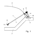
- FIG. 1 an agitator for mixing substrate in containers, especially in fermentation containers.
- a Gährungs employer is composed of a mostly sloping towards the middle sloping gutter 2 and a flexible cover 3.
- the cover 3 is connected to the gutter 2 in a gastight manner.
- Such containers are often used for the production of biogas from biomass.
- the substrate is introduced at one end of the container into the bottom channel 2 and at the other end the residues are discharged again after the gasification process.
- stirrers 1 are provided at the edge of the gutter. These are mounted on a support device 4, which is able to absorb the load of the respective agitator 1.
- the support means 4 may be formed as a strut, which may have an additional support 5, so that the support means 4 is able to absorb horizontal forces.
- the agitator 1 projects with its stirring propeller 8 into the substrate in the gutter 2.
- the connecting pipe 7 is guided through the cover 3 and sealed there with a bushing 9.
- the implementation 9 is arranged so that it is provided at least in the immediate vicinity of the support means 4. Thus, on the one hand movements of the cover 3 when moving the agitator 1 are at least largely avoided. On the other hand, the cover 3 is held by the passage, for example, when the substrate container is re-charged.
- the carrying device 4 engages directly on the passage 9.
- the fulcrum of the agitator 1 then lies almost exactly in the plane of the cover within the passage 9.
- a backup and support strut 10 which engages in the region of the lower end of the support means 4 and with its other end, for example on the drive motor. 6 to attack.
- the propeller 8 is driven by the drive motor 6 via a shaft, not shown.
- This shaft extends in the connecting tube 7 and is gas-tightly sealed with respect to this, for example with shaft seals, so that no gas is able to escape from the container via the connecting tube. In addition, it is also prevented that substrate penetrates into the connecting pipe 7.
- a protection 11 is provided which covers at least a portion of the propeller circumference and thus prevents the propeller can rest directly on the gutter 2 or that the propeller 8 is able to damage the cover 3, when it is lifted from the substrate , or when the cover 3 drops.
- the protection 11 may be formed as a circumferential ring which is fixed to the connecting pipe 7.
- the implementation 9 consists essentially of an inner ring 21, a support ring 22, are formed on the mounting tabs 23 which are connectable to the support means 4, a flexible seal 24 and an outer ring 25.
- the inner diameter of the inner ring 21 and the support ring 22 should be at least as large as the diameter of the guard 11 above the propeller 8, so that the stirring device 1 can be easily pulled out of the container, without the container should be emptied or entered, which then service work is very easy to carry out.
- the outer ring 25 is then simply unscrewed and removed together with the seal 24.
- the passage 9 can be connected, for example via tabs 23 and a bolt 31 1 with the support means 4.
- the bolt 31 may, for example, simultaneously engage in a further holding device 32 which is arranged on the connecting pipe 7 and defines the insertion position of the stirring device 1 and at the same time transmits the weight of the stirring device 1 to the carrying device 4.
- the support means 4 For installation of the stirring device 1 in existing container, the support means 4 is mounted and thus determines the position of the passage 9 on the cover 3. Then, a corresponding hole in the cover 9 are introduced. Then the inner ring 21 and the support ring 22 is mounted. About the tabs 23, the support ring 22 is already connected to the support means 4 and so the cover 3 are held in the later position. Further bushings 9 can now be mounted as well.
- stirring devices 1 Only then are the stirring devices 1 introduced through the openings of the passages 9 into the container.
- the stirring device 1 is with the Carrying device connected for example by bolts 31. Thereafter, the seal 24 and the outer ring 25 is connected to the inner ring 21 and the support ring 22 and so closed the cover again.
- the seal 24 may be formed, for example, as a rubber boot. But it is also conceivable that an at least partially flexible steel seal is provided.
Landscapes
- Chemical & Material Sciences (AREA)
- Chemical Kinetics & Catalysis (AREA)
- Life Sciences & Earth Sciences (AREA)
- Soil Sciences (AREA)
- Environmental Sciences (AREA)
- Mixers Of The Rotary Stirring Type (AREA)
- Accessories For Mixers (AREA)
Abstract
Description
Die Erfindung bezieht sich auf eine Vorrichtung zum Durchmischen des Inhaltes von Substratbehältern mit einem Rührwerk, bestehend aus einem Antriebsmotor, einer Verbindungsstange und am vom Antriebsmotor abgewandten Ende der Verbindungsstange einem Rührpropeller.The invention relates to a device for mixing the contents of substrate containers with a stirrer, consisting of a drive motor, a connecting rod and the end remote from the drive motor of the connecting rod a stirring propeller.
Es sind verschiedene Rührwerke dieser Bauart, insbesondere zum Durchmischen von Gülle, aber auch gerade bei Biogasanlagen zum Durchmischen des zu vergasenden Materials bekannt.There are various stirrers of this type, especially for mixing manure, but also just in biogas plants for mixing the material to be gasified known.
Allen diesen Rührwerken ist gemein, daß diese nur an festen, besonders tragfähigen Becken angebracht werden können. Der Einsatz an offenen, oder mit Planen abgedeckten Becken ist weder vorgesehen noch möglich.All these agitators have in common that they can be attached only to solid, particularly viable pool. The use on open or covered with tarpaulin tanks is neither intended nor possible.
Der vorliegenden Erfindung liegt daher die Aufgabe zugrunde, eine Vorrichtung gemäß dem Oberbegriff des unabhängigen Anspruches vorzuschlagen, die auch bei flachen oder mit Planen abgedeckten Becken einsetzbar ist.The present invention is therefore based on the object to propose a device according to the preamble of the independent claim, which is also used in flat or covered with tarpaulin pools.
Diese Aufgabe wird erfindungsgemäß dadurch gelöst, daß eine Trageinrichtung zur Aufnahme des Gewichtes des Rührwerkes vorgesehen ist.This object is achieved in that a support means for receiving the weight of the agitator is provided.
Damit wird das Rührwerk in Position gehalten und geführt.This will hold and guide the agitator in position.
Sehr vorteilhaft ist es auch, wenn eine Durchführung vorgesehen ist, die in eine nicht tragfähige Abdeckung des Substratbehälters einsetzbar ist und durch die das Rührwerk hindurchragt.It is also very advantageous if a bushing is provided which can be inserted into a non-load-bearing cover of the substrate container and through which the agitator protrudes.
Damit kann eine dichte und bewegliche Durchführung geschaffen werden, die trotzdem nicht das Gewicht des Rührwerkes aufnehmen muss. Es ist auch denkbar, daß die Abdeckung durch die Durchführung in einer vorgegebenen Position gehalten wird. Zudem ist es denkbar, daß flexible Gärbehälter geschaffen werden können, durch deren Wandungn das Rüherwerk hindurchragt.Thus, a dense and mobile implementation can be created, which nevertheless does not have to absorb the weight of the agitator. It is also conceivable that the cover is held by the implementation in a predetermined position. In addition, it is conceivable that flexible fermentation tanks can be created, protrudes through the walls of the Rüherwerk.
Ebenfalls sehr vorteilhaft ist es, wenn die Durchführung mit der Trageinrichtung verbunden ist.It is also very advantageous if the bushing is connected to the carrying device.
Hierdurch werden Kraftübertragungen auf die Abdeckung des Substratbehälters vermieden.As a result, power transmissions are avoided on the cover of the substrate container.
Eine weitere sehr vorteilhafte Ausgestaltung der Erfindung liegt auch vor, wenn das Rührwerk gegenüber der Trageinrichtung und/oder der Durchführung schwenkbar und/oder verschiebbar ist, und/oder daß das Rührwerk um einen Drehpunkt schwenkbar ist, der wenigstens im wesentlichen in der Durchführung liegt.Another very advantageous embodiment of the invention is also present when the agitator with respect to the support means and / or the implementation is pivotable and / or displaceable, and / or that the agitator is pivotable about a pivot point which lies at least substantially in the implementation.
Dadurch werden Relativbewegungen zwischen dem Rührwerk und der Abdeckung weitgehend vermieden. Zudem wird eine optimale Bewegbarkeit des Rührwerks im Substratbehälter sichergestellt.As a result, relative movements between the agitator and the cover are largely avoided. In addition, optimal mobility of the agitator is ensured in the substrate container.
Es hat sich erfindungsgemäß auch als äußerst vorteilhaft erwiesen, wenn die Trageinrichtung als Tragarm ausgebildet ist, der eine zusätzliche Stützstrebe gegen den Untergrund aufweisen kann.It has also proved to be extremely advantageous according to the invention when the carrying device is designed as a support arm, which may have an additional support strut against the ground.
Damit wird eine nochmals verbesserte Stabilität der Trageinrichtung gewährleistet. Auch horizontale Belastungen werden damit von der Konstruktion sicher aufgenommen.For a further improved stability of the support device is ensured. Even horizontal loads are thus safely absorbed by the design.
Eine weitere sehr vorteilhafte Ausgestaltung der Erfindung liegt auch vor, wenn die Trageinrichtung eine längenverstellbare Strebe zur Einstellung der Vertikal- und oder Horizontalposition des Anlenkpunktes des Rührwerkes und/oder des Rührwerkes aufweist.Another very advantageous embodiment of the invention is also present when the support device has a length-adjustable strut for adjusting the vertical and or horizontal position of the articulation point of the agitator and / or the agitator.
Damit kann nicht nur die Position des Anlenkpunktes des Rührwerkes, sondern auch die der Durchführung und die Position des Rührwerkes im Behälter eingestellt werden.Thus, not only the position of the articulation point of the agitator, but also the implementation and the position of the agitator can be set in the container.
Gemäß einer weiteren sehr vorteilhaften Weiterbildung der Erfindung kann auch das Rührwerk lösbar mit der Trageinrichtung und der Durchführung verbunden sein.According to a further very advantageous embodiment of the invention, the agitator can be releasably connected to the support means and the implementation.
Dadurch wird nicht nur der nachträgliche Einbau des Rührwerks in bestehende Substratbehälter erleichtert, sondern auch der Service und/oder der Austausch von Teilen kann sehr leicht durchgeführt werden.This not only facilitates the subsequent installation of the agitator in existing substrate container, but also the service and / or the replacement of parts can be carried out very easily.
Ebenfalls äußerst vorteilhaft ist es erfindungsgemäß, wenn die Durchführung eine flüssigkeits- und/oder gasdichte Abdichtung zur Verbindungsstange hin aufweist.It is also extremely advantageous according to the invention if the bushing has a liquid-tight and / or gas-tight seal towards the connecting rod.
Damit kann der Substratbehälter dicht zur Umgebung abgeschlossen werden. Der Einsatz des Rührwerkes ist auch bei Substratbehältern denkbar, deren Abdeckung im Betrieb durch die entstehenden Gase angehoben und zumindest geringfügig aufgebläht wird.Thus, the substrate container can be sealed tight to the environment. The use of the agitator is also conceivable for substrate containers whose cover is raised in operation by the resulting gases and at least slightly inflated.
Äußerst vorteilhaft ist es erfindungsgemäß auch, wenn die Verbindungsstange längsverschiebbar und/oder längenverstellbar ausgebildet ist.It is also extremely advantageous according to the invention if the connecting rod is longitudinally displaceable and / or length-adjustable.
Damit kann ein sehr großer Bereich im Substratbehälter erreicht werden. Eine gute Durchmischung wird sichergestellt.Thus, a very large area can be achieved in the substrate container. Good mixing is ensured.
Eine weitere sehr vorteilhafte Ausgestaltung liegt auch vor, wenn dem Propeller eine wenigstens teilweise umlaufende Schutzeinrichtung zugeordnet ist.Another very advantageous embodiment is also present when the propeller is associated with an at least partially encircling protection device.
Dadurch wird einerseits verhindert, daß der Propeller auf dem Untergrund des Behälter direkt aufliegen kann und andererseits sichergestellt, daß der Propeller nicht etwa Behälterwandungen beschädigt, was vor allem bei flexiblen Wandungen ein Problem darstellen kann.This prevents on the one hand that the propeller can rest directly on the ground of the container and on the other hand ensures that the propeller does not damage container walls, which can be a problem especially in flexible walls.
Im folgenden wird die Erfindung anhand eines Ausführungsbeispiels veranschaulicht.In the following the invention is illustrated by means of an embodiment.
Dabei zeigen:
- Fig. 1
- eine schematische Darstellung eines erfindungsgemäßen Rührwerkes, welches in einem Substratbehälter mit einer flexiblen Abdeckung angeordnet ist,
- Fig. 2
- eine Detailansicht der Trageinrichtung mit Durchführung und Antriebsmotor,
- Fig. 3
- eine Explosionsdarstellung der Durchführung mit der Trageinrichtung, und
- Fig. 4
- eine Detailansicht des Rührpropellers.
- Fig. 1
- a schematic representation of an agitator according to the invention, which is arranged in a substrate container with a flexible cover,
- Fig. 2
- a detailed view of the support device with implementation and drive motor,
- Fig. 3
- an exploded view of the implementation with the support means, and
- Fig. 4
- a detailed view of the stirring propeller.
Mit 1 ist in
Dabei kommt es jedoch zu Ablagerungen von Substrat in der Bodenrinne 2, so daß keine ausreichende Vergasung stattfinden kann.However, it comes to deposits of substrate in the
Um dies zu verhindern wird ein oder mehrere Rührwerke 1 am Rand der Bodenrinne vorgesehen. Diese sind auf einer Trageinrichtung 4 gelagert, welche die Last des jeweiligen Rührwerks 1 aufzunehmen vermag. Die Trageinrichtung 4 kann dabei als Strebe ausgebildet sein, die eine zusätzliche Stütze 5 aufweisen kann, so daß die Trageinrichtung 4 auch horizontale Kräfte aufzunehmen vermag.To prevent this, one or
Auf der Trageinrichtung 4 ruht das im wesentlichen aus einem Antriebsmotor 6, einem Verbindungsrohr 7 und am vom Antriebsmotor 6 abgewandten Ende des Verbindungsrohres 7 angeordneten Rührpropeller 8 bestehenden Rührwerk 1.On the support means 4 rests the substantially consisting of a
Das Rührwerk 1 ragt mit seinem Rührpropeller 8 in das Substrat in der Bodenrinne 2 hinein. Dazu ist das Verbindungrohr 7 durch die Abdeckung 3 geführt und dort mit einer Durchführung 9 abgedichtet.The
Die Durchführung 9 ist dabei so angeordnet, daß diese zumindest in direkter Nähe zur Trageinrichtung 4 vorgesehen ist. So werden einerseits Bewegungen der Abdeckung 3 beim Bewegen des Rührwerkes 1 wenigstens weitgehend vermieden. Andererseits wird auch die Abdeckung 3 durch die Durchführung gehalten, wenn zum Beispiel der Substratbehälter neu beschickt wird.The
Im Idealfall greift die Trageinrichtung 4 direkt an der Durchführung 9 an. Der Drehpunkt des Rührwerkes 1 liegt dann ziemlich genau in der Ebene der Abdeckung innerhalb der Durchführung 9.Ideally, the
Um die Position des Propellers 8 im Substrat vorgeben zu können und/oder um eine bestimmte Bewegungsbahn vorgeben zu können kann eine Sicherungs- und Stützstrebe 10 vorgesehen sein, die im Bereich des unteren Endes der Stützeinrichtung 4 angreift und mit ihrem anderen Ende beispielsweise am Antriebsmotor 6 anzugreifen vermag.In order to specify the position of the
Durch diese Stützstrebe 10 wird der Abstand zwischen Antriebsmotor und Grund gehalten.By this
Der Propeller 8 wird vom Antriebsmotor 6 über eine nicht dargestellte Welle angetrieben. Diese Welle verläuft im Verbindungsrohr 7 und ist gegenüber diesem zum Beispiel mit Wellendichtringen gasdicht abgedichtet, so daß über das Verbindungsrohr kein Gas aus dem Behälter zu entweichen vermag. Zusätzlich wird so auch verhindert, daß Substrat in das Verbindungsrohr 7 eindringt.The
Um den Propeller 8 ist ein Schutz 11 vorgesehen, der wenigstens einen Teilbereich der Propellerumfanges abdeckt und so verhindert, daß der Propeller direkt auf der Bodenrinne 2 aufliegen kann oder daß der Propeller 8 die Abdeckung 3 zu beschädigen vermag, wenn dieser aus dem Substrat gehoben wird, oder wenn die Abdeckung 3 absinkt.To the
Der Schutz 11 kann dabei als umlaufender Ring ausgebildet sein, der am Verbindungsrohr 7 befestigt ist.The
Die Durchführung 9 besteht im wesentlichen aus einem Innenring 21, einem Tragring 22, an den Befestigungslaschen 23 angeformt sind, die mit der Trageinrichtung 4 verbindbar sind, einer flexiblen Dichtung 24 und einem Außenring 25. Durch diesen Aufbau wird eine absolut dichte Verbindung zwischen Verbindungsrohr 7 und der Abdeckung 3 geschaffen.The
Der Innendurchmesser des Innenrings 21 und des Tragrings 22 sollte wenigstens so groß sein, wie der Durchmesser des Schutzes 11 über dem Propeller 8, so daß die Rühreinrichtung 1 aus dem Behälter einfach herausgezogen werden kann, ohne daß der Behälter entleert oder betreten werden müsste, wodurch dann Servicearbeiten sehr einfach durchführbar sind.The inner diameter of the
Um die Rühreinrichtung 1 herauszuziehen wird dann einfach der Außenring 25 abgeschraubt und zusammen mit der Dichtung 24 entfernt.In order to extract the stirring
Die Durchführung 9 kann beispielsweise über Laschen 23 und mit einem Bolzen 31 1 mit der Trageinrichtung 4 verbunden werden. Der Bolzen 31 kann beispielsweise gleichzeitig in eine weitere Halteeinrichtung 32 eingreifen, welche am Verbindungsrohr 7 angeordnet ist und die Einschieb-Position der Rühreinrichtung 1 definiert und zugleich das Gewicht der Rühreinrichtung 1 auf die Trageinrichtung 4 überträgt.The
Es ist denkbar, daß mehrere Bolzen 31 vorgesehen sein können.It is conceivable that a plurality of
Zum Einbau der Rühreinrichtung 1 in bestehende Behälter wird die Trageinrichtung 4 angebracht und so die Position der Durchführung 9 an der Abdeckung 3 bestimmt. Dann kann ein entsprechendes Loch in die Abdeckung 9 eingebracht werden. Hierauf wird der Innenring 21 und der Tragring 22 montiert. Über die Laschen 23 kann der Tragring 22 bereits mit der Trageinrichtung 4 verbunden und so die Abdeckung 3 in der späteren Position gehalten werden. Weitere Durchführungen 9 können nun ebenso montiert werden.For installation of the stirring
Erst anschließend werden die Rühreinrichtungen 1 durch die Öffnungen der Durchführungen 9 in den Behälter eingeführt. Die Rühreinrichtung 1 wird mit der Trageinrichtung zum Beispiel durch Bolzen 31 verbunden. Danach wird die Dichtung 24 und der Außenring 25 mit dem Innenring 21 und dem Tragring 22 verbunden und so die Abdeckung wieder verschlossen.Only then are the stirring
Dabei liegt die Dichtung 24 dicht am Verbindungrohr 7 an.In this case, the
Die Dichtung 24 kann beispielsweise als Gummimanschette ausgebildet sein. Es ist aber auch denkbar, daß eine wenigstens teilweise flexible Stahldichtung vorgesehen wird.The
Claims (10)
Applications Claiming Priority (1)
| Application Number | Priority Date | Filing Date | Title |
|---|---|---|---|
| DE102010000489A DE102010000489B4 (en) | 2010-02-21 | 2010-02-21 | contraption |
Publications (2)
| Publication Number | Publication Date |
|---|---|
| EP2361673A2 true EP2361673A2 (en) | 2011-08-31 |
| EP2361673A3 EP2361673A3 (en) | 2013-01-02 |
Family
ID=44010122
Family Applications (1)
| Application Number | Title | Priority Date | Filing Date |
|---|---|---|---|
| EP11154905A Withdrawn EP2361673A3 (en) | 2010-02-21 | 2011-02-17 | Apparatus |
Country Status (4)
| Country | Link |
|---|---|
| US (1) | US20110205833A1 (en) |
| EP (1) | EP2361673A3 (en) |
| BR (1) | BRPI1002134A2 (en) |
| DE (1) | DE102010000489B4 (en) |
Families Citing this family (4)
| Publication number | Priority date | Publication date | Assignee | Title |
|---|---|---|---|---|
| SE534766C2 (en) * | 2010-04-26 | 2011-12-13 | Itt Mfg Enterprises Inc | Implementation for digestion |
| US8721166B1 (en) * | 2013-01-15 | 2014-05-13 | The Maitland Company | Agitation and evacuation of refinery solids waste |
| CN109337799B (en) * | 2018-11-06 | 2023-08-25 | 胡小鹤 | Integrated anaerobic fermentation device |
| CN114377583B (en) * | 2022-03-24 | 2022-06-07 | 诸城市中裕机电设备有限公司 | Feed mixing device for livestock breeding |
Family Cites Families (24)
| Publication number | Priority date | Publication date | Assignee | Title |
|---|---|---|---|---|
| US1703099A (en) * | 1923-07-31 | 1929-02-26 | Frederick L Craddock | Mixing device |
| US1693170A (en) * | 1925-03-30 | 1928-11-27 | Alsop Samuel | Mixer |
| US1817353A (en) * | 1929-08-28 | 1931-08-04 | Mixing Equipment Company Inc | Safety mixer |
| US2042511A (en) * | 1931-10-17 | 1936-06-02 | Mixing Equipment Company Inc | Safety mixer |
| US2116099A (en) * | 1936-09-04 | 1938-05-03 | Us Stoneware Co | Sealing, supporting, and cushioning assembly |
| US2209287A (en) * | 1938-04-07 | 1940-07-23 | Wilbur L Simpson | Apparatus for mixing |
| US2376722A (en) * | 1943-07-01 | 1945-05-22 | Abram I Podell | Mixing attachment |
| AT241276B (en) * | 1963-05-20 | 1965-07-12 | Bauer Roehren Pumpen | Mixing and delivery pump |
| US3223389A (en) * | 1964-02-10 | 1965-12-14 | Clyde S Simmonds | Paint mixer |
| US3425835A (en) * | 1964-03-30 | 1969-02-04 | Eastman Kodak Co | Method for dispersing non-aqueous solution in aqueous gelatin solutions using an aspirating agitator |
| FR1578343A (en) * | 1967-08-11 | 1969-08-14 | ||
| DE2124313A1 (en) * | 1971-05-17 | 1972-11-30 | Kupka D | Side entry tank agitator - has angled shaft describing cone surface outline while agitator revolves |
| US4396291A (en) * | 1982-03-18 | 1983-08-02 | William Simmonds | Motor driven paint mixer |
| US4844843A (en) * | 1987-11-02 | 1989-07-04 | Rajendren Richard B | Waste water aerator having rotating compression blades |
| DE4124912A1 (en) * | 1991-07-26 | 1993-01-28 | Henkel Kgaa | DEVICE AND METHOD FOR DOSING POWDER DIRECTLY FROM THE SALES CONTAINER |
| US5226727A (en) * | 1991-09-30 | 1993-07-13 | Reichner Thomas W | Agitator/mixer |
| US6572261B1 (en) * | 2001-06-12 | 2003-06-03 | Walker Stainless Equipment Company | Horizontal agitator |
| EP1310292A1 (en) * | 2001-11-13 | 2003-05-14 | Maschinenbau Peters S.P.R.L. | Movable stirring apparatus |
| DE202004004101U1 (en) * | 2004-03-16 | 2004-07-29 | U.T.S. Umwelt-Technik-Süd GmbH | Fermenter of a biogas plant with a stirring device |
| DE202005017638U1 (en) * | 2005-11-09 | 2006-04-06 | Envicon Klärtechnik Verwaltungsgesellschaft mbH | Mounting for submersible stirrers in biogas generators comprises rail mounted on pivot on tank wall, allowing stirrer to be lowered into it, and hydraulic or electrical stirrer drive fitted inside rail |
| DE202006013548U1 (en) * | 2006-09-01 | 2008-01-10 | Envicon Klärtechnik GmbH & Co. KG | Stirring device for a gas-tight sealed container |
| DE102007022902A1 (en) * | 2007-05-14 | 2008-11-20 | Karl Buschmann Maschinenbau Gmbh | Conveying system of a fermentation or digestion tank |
| DE102007060608B4 (en) * | 2007-12-13 | 2013-03-14 | Thürwächter GmbH & Co. KG | Wall bushing |
| AT507028B1 (en) * | 2008-06-25 | 2012-07-15 | Sattler Ag | ERDBECKENFERMENTER |
-
2010
- 2010-02-21 DE DE102010000489A patent/DE102010000489B4/en not_active Expired - Fee Related
- 2010-06-04 BR BRPI1002134-5A patent/BRPI1002134A2/en not_active IP Right Cessation
-
2011
- 2011-02-17 EP EP11154905A patent/EP2361673A3/en not_active Withdrawn
- 2011-02-17 US US12/932,118 patent/US20110205833A1/en not_active Abandoned
Non-Patent Citations (1)
| Title |
|---|
| None |
Also Published As
| Publication number | Publication date |
|---|---|
| DE102010000489B4 (en) | 2012-07-26 |
| DE102010000489A1 (en) | 2011-08-25 |
| US20110205833A1 (en) | 2011-08-25 |
| EP2361673A3 (en) | 2013-01-02 |
| BRPI1002134A2 (en) | 2011-11-01 |
Similar Documents
| Publication | Publication Date | Title |
|---|---|---|
| EP1992405B1 (en) | Conveying system of a fermentation/digestion tank | |
| DE102005041798B4 (en) | Fermenter and method for operating a fermenter | |
| EP2270128B1 (en) | Biogas facility and manhole for a biogas facility | |
| EP2389432B1 (en) | Biogas plant service device | |
| DE202004004101U1 (en) | Fermenter of a biogas plant with a stirring device | |
| DE202006013772U1 (en) | Biogas production plant comprises housing, fermentation tank to receive fermentation material, biogas storage connected with the fermentation tank, and feeding device to supply solid fermentation material into the fermentation | |
| EP2878365B1 (en) | Agitator for a biogas fermenter | |
| DE102007005069A1 (en) | Biogas plant for continuous single step working process, has main fermenter container and post fermenter container, where both containers have gas proof container cover and gas tank, and are assembled in fermenter network | |
| EP2361673A2 (en) | Apparatus | |
| EP3898930A1 (en) | Container and method for installing an agitator in a container | |
| DE102018000927A1 (en) | Biogas plant fermenter tank, service facility for installation on a biogas plant fermenter tank and method for operating a biogas plant fermenter tank | |
| EP2914709B1 (en) | Fermenter of a biogas system | |
| DE102011114793A1 (en) | Cylindrical mashing container used for biogasification, has filling opening which is formed in ceiling, and a mixer positioned with respect to filling opening such that the container is re-fed to a substrate | |
| EP1619239A2 (en) | Biogas plant for the fermentation of organic material | |
| EP1876229A1 (en) | Bio gas facility for fermenting organic substances | |
| DE102005031221A1 (en) | screening device | |
| DE202009017017U1 (en) | Digester for the production of biogas, with container pot, film hood and a vertical, accessible from the outside agitator | |
| EP0127769B1 (en) | Plant having containers made of synthetic tarpaulins for the progressive (aerobic and anaerobic) fermentation of animal manure and agricultural and/or food factory by-products | |
| DE202007018863U1 (en) | Fermentation or digester | |
| EP2826549B1 (en) | Device for mixing the content of substrate containers | |
| WO2019029913A1 (en) | Mixing device and method for operating a mixing device | |
| DE102020116333A1 (en) | Gas-tight container | |
| DE102011081431A1 (en) | Fermentation- or digestion tank, comprises a container wall and a mounting shaft for accommodating a removable agitator, which passes through container wall, where agitator is introduced into fixed mounting shaft through mounting unit | |
| EP1925564B1 (en) | Fastening unit | |
| WO2015135616A1 (en) | Apparatus for fermenting biomass for production of gas |
Legal Events
| Date | Code | Title | Description |
|---|---|---|---|
| PUAI | Public reference made under article 153(3) epc to a published international application that has entered the european phase |
Free format text: ORIGINAL CODE: 0009012 |
|
| AK | Designated contracting states |
Kind code of ref document: A2 Designated state(s): AL AT BE BG CH CY CZ DE DK EE ES FI FR GB GR HR HU IE IS IT LI LT LU LV MC MK MT NL NO PL PT RO RS SE SI SK SM TR |
|
| AX | Request for extension of the european patent |
Extension state: BA ME |
|
| PUAL | Search report despatched |
Free format text: ORIGINAL CODE: 0009013 |
|
| AK | Designated contracting states |
Kind code of ref document: A3 Designated state(s): AL AT BE BG CH CY CZ DE DK EE ES FI FR GB GR HR HU IE IS IT LI LT LU LV MC MK MT NL NO PL PT RO RS SE SI SK SM TR |
|
| AX | Request for extension of the european patent |
Extension state: BA ME |
|
| RIC1 | Information provided on ipc code assigned before grant |
Ipc: A01C 3/02 20060101ALI20121126BHEP Ipc: B01F 15/00 20060101AFI20121126BHEP Ipc: B01F 7/00 20060101ALI20121126BHEP Ipc: F16M 11/00 20060101ALI20121126BHEP Ipc: C12M 1/107 20060101ALI20121126BHEP |
|
| 17P | Request for examination filed |
Effective date: 20130225 |
|
| 17Q | First examination report despatched |
Effective date: 20131105 |
|
| GRAP | Despatch of communication of intention to grant a patent |
Free format text: ORIGINAL CODE: EPIDOSNIGR1 |
|
| INTG | Intention to grant announced |
Effective date: 20151113 |
|
| STAA | Information on the status of an ep patent application or granted ep patent |
Free format text: STATUS: THE APPLICATION IS DEEMED TO BE WITHDRAWN |
|
| 18D | Application deemed to be withdrawn |
Effective date: 20160315 |