EP2361003A2 - Use of token switch to indicate unauthorized manipulation of a protected device - Google Patents
Use of token switch to indicate unauthorized manipulation of a protected device Download PDFInfo
- Publication number
- EP2361003A2 EP2361003A2 EP11153599A EP11153599A EP2361003A2 EP 2361003 A2 EP2361003 A2 EP 2361003A2 EP 11153599 A EP11153599 A EP 11153599A EP 11153599 A EP11153599 A EP 11153599A EP 2361003 A2 EP2361003 A2 EP 2361003A2
- Authority
- EP
- European Patent Office
- Prior art keywords
- housing
- plunger
- circuit
- register
- token switch
- Prior art date
- Legal status (The legal status is an assumption and is not a legal conclusion. Google has not performed a legal analysis and makes no representation as to the accuracy of the status listed.)
- Withdrawn
Links
Images


Classifications
-
- H—ELECTRICITY
- H05—ELECTRIC TECHNIQUES NOT OTHERWISE PROVIDED FOR
- H05K—PRINTED CIRCUITS; CASINGS OR CONSTRUCTIONAL DETAILS OF ELECTRIC APPARATUS; MANUFACTURE OF ASSEMBLAGES OF ELECTRICAL COMPONENTS
- H05K5/00—Casings, cabinets or drawers for electric apparatus
- H05K5/02—Details
- H05K5/0208—Interlock mechanisms; Means for avoiding unauthorised use or function, e.g. tamperproof
Definitions
- Some electronic components are sensitive to tampering and will no longer function properly if the housing in which the electronic component is enclosed is opened. If the user of such a component attempts to undertake repairs or to examine the electronic component, the user may unwittingly render the electronic component inaccurate and/or unusable.
- the present application relates to an apparatus to indicate unauthorized manipulation of at least one protected device enclosed in a housing.
- the apparatus includes a structure attached to a first portion of the housing and a token switch attached to a second portion of the housing.
- the token switch is operably positioned with reference to the structure.
- the token switch includes a plunger, and a register programmed with a value.
- the register is communicatively coupled with a processor in a circuit.
- the circuit is communicatively coupled to drive the device.
- the structure, the token switch, and the circuit are internal to the housing when the housing is in a closed position.
- the plunger and the structure are positioned to generate a current when the housing is opened.
- the programmed value in the register is changed by the generated current and the processor takes an action responsive to the change in the programmed value.
- Electronic and/or optical components that are sensitive to tampering may be rendered inaccurate if the electronic and/or optical component is disturbed and/or misaligned by a non-skilled technician. It is advantageous that the electronic and/or optical component be rendered inoperable or flagged as erroneous if tampered with, in order to prevent use of the inaccurate electronic and/or optical components, since use of an inaccurate electronic and/or optical component can cause degraded performance or malfunction. If the electronic and/or optical component is part of a safety critical device, degraded performance or malfunction can have unfortunate consequences. For example, gyroscopes used in navigation systems are very sensitive to misalignments caused by tampering.
- Tampering or unauthorized manipulation of a protected electronic and/or optical component typically occurs when the electronic and/or optical component is powered down.
- the embodiments of the apparatus and methods described herein can be implemented with or without the electronic and/or optical component and/or related circuitry being powered up.
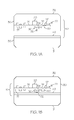
- Figures 1A and 1B are an embodiment of an apparatus 10 to indicate unauthorized manipulation of at least one protected device 20 enclosed in a housing 30 in accordance with the present invention.
- Figure 1A is an embodiment of the apparatus 10 to protect a device 20 when the housing 30 is in the open position.
- Figure 1B is an embodiment of the apparatus 10 to protect a device 20 when the housing 30 is in the closed position.
- the device 20 is one or more of an optical device, an electronic device, an opto-electronic device.
- the device 20 is a gyroscope 20.
- the device 20 is a ring-laser gyroscope 20.
- the device 20 is an accelerometer 20.
- the device 20 includes at one or more of at least one navigation sensor, at least one inertial sensor, at least one gyroscope, at least one accelerometer, at least one magnetometer, at least one pressure sensor, at least one air data sensor, and other types of safety critical devices.
- the apparatus 10 includes a structure 40 attached to a first portion 31 of the housing 30, the token switch 50 attached to a second portion 32 of the housing 30, and a circuit 70 communicatively coupled to drive the device 20.
- the structure 40 is a plate 40 that extends across an opening in the first portion 31 of the housing 30.
- the structure 40 is a ledge in the first portion 31 or a protrusion from a floor of the first portion 31 that extends into at least a portion of a center region of the housing.
- structure and “plate” are used interchangeably herein.
- the token switch 50 includes a plunger 52 and at least one register 54, which is programmed with an initial value prior to operation of the circuit 70.
- the value is a randomized constant value that is known to registered users and is unknown to unregistered users.
- the register 54 is communicatively coupled with a processor 60 in the circuit 70.
- the processor 60 reads the value in the register 54 when the circuit 70 is powered up.
- the circuit 70 is communicatively coupled to drive the device 20.
- the circuit 70 is a surface mounted circuit card on a printed circuit board (PCB) 75.
- the PCB 75 has a top surface 76 and an opposing bottom surface 77.
- the token switch 50 is attached to the bottom surface 77 of the PCB 75.
- the plate 40, the token switch 50, the circuit 70, and the device 20 are internal to the housing 30 when the housing 30 is in a closed position.
- the plunger 52 and the plate 40 are positioned to generate a current when the housing 30 is opened.
- the current changes the programmed value stored in the register 54.
- the current nulls the programmed value stored in the register 54.
- the current is generated without a power source so that the detection of manipulation of a protected device 20 occurs when the circuit 70 is powered down.
- the detection of manipulation of a protected device 20 can also occur when the device is powered up.
- the processor 60 detects the change in the state of the register 54 and takes an action.
- the token switch 50 is a magnetic token switch 150.
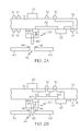
- Figure 2A shows an enlarged view of an embodiment of a magnetic token switch 150 in position with a portion of the plate 141 when the housing 30 is in the open position ( Figure 1A ) in accordance with the present invention.
- the structure attached to a first portion 31 of the housing 30 is a plate 140 with a hole 142 encircled by a magnetic material 145.
- the magnetic token switch 150 has a magnetic plunger 152 formed from a magnetic material.
- Figure 2B shows an enlarged view of the magnetic token switch 50 of Figure 2A when the housing 30 is in the closed position ( Figure 1B ).
- the magnetic plunger 152 and the plate 140 are configured so that the magnetic plunger 152 is positioned external to the hole 142 when the housing 30 is open and so that the magnetic plunger 152 is positioned inside of the hole 142 and encircled by the magnetic material 145 when the housing 30 is closed. In this manner, when the housing 30 is opened from the closed position, the movement of the magnetic plunger 152 out of the hole 142, generates current due to the movement of the magnetic plunger 152 from inside of the magnetic ring 145 to outside of the magnetic ring 145.
- the magnetic ring 145 is a permanent magnet. As shown in Figure 2A , the current i is transmitted from the magnetic plunger 152 to the register 154 via link 66. When the current i is received at the register 154, the value in the register 154 is changed or cleared.
- the value in the register 154 is programmed once the housing 30 is closed and the magnetic plunger 152 is inside the magnetic ring 145.
- the value in the register 154 is a password or code that is known by the manufacturer who assembles the device 20 in the housing 30 and/or is known by a skilled technician who is authorized to work on the device 20 in the housing 30.
- the value stored in the register 154 is also stored as a password or code in a memory 57 that is communicatively coupled to the processor 60 when the apparatus 10 is manufactured and/or initialized. In one implementation of this embodiment, the value stored in the register 154 is also stored as a password or code in the processor 60.
- the processor 60 Each time that the protected device 20 in the housing 30 is powered up, the processor 60 reads the value of the register 154 via link 62, and checks to make sure that the value in the register 154 matches a password or code stored in the memory 57. The processor 60 permits the circuit 70 to operate once the password is determined to match the value in the register 154.
- the circuit 70 drives the protected device 20.
- the protected device 20 includes more than one device 20, such as at least one navigation sensor, at least one inertial sensor, at least one gyroscope, at least one accelerometer, at least one magnetometer, at least one pressure sensor, and/or at least one air data sensor (or other safety critical devices), the circuit 70 runs the two or more devices. Exemplary links 163 within the printed circuit board 75, communicatively couple the processor 60, circuit 70, and the protected device 20.
- the processor 60 is prompted to take an action.
- the action taken by the processor 60 indicates to a user that the housing 30 has been opened.
- the processor 60 can set a flag to indicate that the housing 30 has been opened.
- the processor 60 renders the circuit 70 inoperable to drive the device 20 if the housing 30 has been opened.
- the processor 60 causes the circuit 70 to operate the device 20 in a degraded manner if the housing 30 has been opened.
- the processor 60 causes the circuit 70 to display a message to the user indicating an error in the device 20 or a tampering with the housing 30 if the housing 30 has been opened. In some embodiments, more than one of these actions is taken when the housing is opened.
- a registered technician opens the housing 30 to perform maintenance or other procedures, the registered technician reprograms the register 154 with the password that is recognizable by the processor 60 after the maintenance is completed and the housing 30 is closed again. If an unregistered user opens the housing 30, the unregistered user is unable to reprogram the register 154 with the value that is recognizable by the processor 60 as the password, since the unregistered user does not know the password.
- the memory 57 comprises any suitable memory now known or later developed such as, for example, random access memory (RAM), read only memory (ROM), and/or registers within the processor 60.
- the processor 60 comprises a microprocessor or microcontroller.
- the processor 60 and memory 57 are shown as separate elements in Figure 1 , in one implementation, the processor 60 and memory 57 are implemented in a single device (for example, a single integrated-circuit device).
- the processor 60 comprises processor support chips and/or system support chips such as application-specific integrated circuits (ASICs).
- ASICs application-specific integrated circuits
- the processor 60 executes software (not shown) stored in a storage medium (not shown) to make the processor take the actions described herein.
- the software executed by the processor 60 is stored in the processor 60 or in the memory 57.
- the hole 142 is shown to extend completely through the plate 140.
- the hole 142 is a cavity of sufficient depth for the magnetic plunger 152 to extend at least partially into the cavity without touching the plate 140.
- the entrance to the cavity is enclosed by a magnetic material 145 or the inside of the cavity is encircled with the magnetic material 145.
- FIGS 2A and 2B shows views of an embodiment of a plate 141 having a hole 142 encircled by a magnetic ring 146 in accordance with the present invention.
- Figure 3A is a top view of the plate 141.
- Figure 3B is a cross-sectional side view of the plate 141. The plane upon which the cross-section view of Figure 3B is taken is indicated by section line 3B-3B in Figure 3A .
- the plate 141 includes a permanent magnet 146 with a hole 142 extending through the permanent magnet 146. Other configurations for encircling a hole in a plate with a permanent magnet are possible.
- the token switch 50 in the apparatus 10 is a piezoelectric token switch 120 as shown in Figures 4A-4C .
- the piezoelectric token switch 120 includes at least one register 137, a piezoelectric element 125, and a plunger 130.
- the plunger 130 is operably positioned to be in a retracted mode as shown in Figure 4A or an extended mode as shown in Figure 4C .
- the plunger 130 applies a first pressure to the piezoelectric element 125 as indicated by the arrow F1.
- the plunger 130 applies a second pressure, as indicated by the arrow F, to the piezoelectric element 125.
- the second pressure is less than the first pressure.
- snap mechanism 133 is positioned within the plunger 130.
- the snap mechanism 133 indicated in this embodiment, as a spring is held within the plunger 130 by an indent 131 in an end surface 132 of the plunger 130.
- the snap mechanism 133 ensures that the pressure change on the piezoelectric element 125 is abrupt enough to generate the current. In this manner, a slow gradual opening of the housing 30, which would allow incremental changes to the pressure on the piezoelectric element 125, is not possible. The incremental changes in pressure of the piezoelectric element 125 could result in no current being transmitted from the piezoelectric element 125 to the register 137.
- FIG 4A shows an enlarged view of an embodiment of a piezoelectric token switch 120 in contact with the plate 40 when the housing 30 is in the closed position in accordance with the present invention.
- the snap mechanism 133 is the spring 133 that is compressed between a floor 135 of the indent 131 and the top surface 143 of the plate 40.
- the plunger 130 applies the first pressure to the piezoelectric element 125 as indicated by the arrow F1.
- the first pressure P1 equals F1 divided by the unit area of the end face 136 of the plunger 130.
- Figure 4B shows the enlarged view of the piezoelectric token switch 120 of Figure 4A when the housing 30 is in the initial stages of being opened.
- the distance between the PCB 75 and the top surface 143 of the plate 40 has increased to D2.
- the snap mechanism 133 is still under compression since the spring 133 is still compressed between the floor 135 of the indent 131 and the top surface 143 of the plate 40.
- the pressure on the piezoelectric element 125 is approximately F1.
- the pressure may be slightly less that the first pressure depending on the design of the spring 133 and the plunger 130 since the compression on the spring 133 is reduced.
- a threshold indicative of an opening of the housing 30 is set by the snap mechanism 133.
- the threshold indicative of an opening of the housing 30 is exceeded when the spring 133 no longer forces the plunger 130 against the piezoelectric element 125.
- Other types of snap mechanisms are possible. All the types of snap mechanisms cause the quick change in pressure on the piezoelectric element 125 even if there is a slow gradual opening of the housing 30.
- Figure 4C shows the enlarged view of the piezoelectric token switch 120 of Figures 4A and 4B when the housing 30 is completely open.
- the distance between the PCB 75 and the top surface 143 of the plate 40 has increased to D3.
- the spring 133 is no longer compressed between the floor 135 of the indent 131 and the top surface 143 of the plate 40.
- the change in pressure on the piezoelectric element 125 generates a charge since plunger 130 there is a change in pressure on the piezoelectric element 125.
- a current is generated by a change in pressure on a piezoelectric element 125.
- there is zero pressure (F 0) on the piezoelectric element 125 since the plunger 130 does not contact the piezoelectric element 125.
- the second pressure is non-zero and is less than the first pressure and the change in pressure occurs over a sufficiently short duration and is of sufficient difference to generate a current.
- the generated current is transmitted to the register 137 via link 138.
- Figure 5 illustrates a flow chart, representative of an embodiment of a method 500 of indicating unauthorized manipulation of a protected device 20 enclosed in housing 30 in accordance with the present invention.
- Method 500 can be implemented by the apparatus 10 illustrated in Figures 1A and 1B , in which the token switch 50 is the magnetic token switch 150 shown in Figures 2A and 2B .
- method 500 can be implemented by the apparatus 10 illustrated in illustrated in Figures 1A and 1B in which the token switch is the piezoelectric token switch 120 shown in Figures 4A-4C .
- At block 502 at least one register 54 in the token switch 50 is communicatively coupled to a processor 60 in circuit 70 on a PCB 75.
- a protected device 20 is also attached to the PCB 75.
- the circuit 70 is configured to drive the protected device 20.
- the circuit 70 can be on the top surface 76 of the PCB 75 or the bottom surface 77 of the PCB 75 as shown in Figure 2A .
- the token switch 50 is attached to the bottom surface 77 of the PCB 75.
- the processor 60 in the circuit 70 is programmed to take an action when a value in the register 54 is modified.
- the action can be to shut down the circuit 70 to render it inoperable, to set a flag in the circuit 70, to degrade the performance of the protected device 20, or to send an indication of tampering to a user of the protected device 20 when it is powered up the next time.
- a structure 40 is positioned on a first portion 31 of the housing 30.
- the structure 40 positioned in the first portion 31 of the housing 30 is the plate 140 having a hole 142 encircled by a magnetic ring 145.
- the structure 40 positioned in the first portion 31 of the housing 30 is the plate 40.
- the first portion 31 of the housing is a bottom portion of the housing for a gyroscope 20.
- a token switch 50 is positioned on a second portion 32 of the housing 30.
- the relative position of the token switch 50 and the structure 40 is such that the plunger 52 and structure 40 are positioned to generate a current that changes the register 54 in the token switch 50 when the housing 30 is opened, as is understandable to one skilled in the art upon reading this document.
- the token switch 50 positioned on the second portion 32 is the magnetic token switch 150 and the plate positioned in the first portion 31 of the housing 30 during block 506 was the plate 140 having a hole 142 encircled by a magnetic ring 145.
- the token switch 50 positioned on the second portion 32 is the piezoelectric token switch 120 and the plate positioned in the first portion 31 of the housing 30 during block 506 was the plate 40 that does not require a hole 142.
- the second portion 32 of the housing 30 is a top portion 32 of the housing for a gyroscope 20.
- the first portion 31 of the housing 30 is attached to the second portion 32 of the housing 30. This is an optional step.
- the attachment used to connect the first portion 31 to the second portion 32 is a hinging apparatus.
- the housing 30 is closed so that the token switch 50 is operable to generate a current to change the value in the register 54 in the token switch 50 when the housing 30 is opened.
- the first portion 31 is mated to the second portion 32. If block 510 is not an implemented step in method 500, then the first portion 31 to the second portion 32 are mated together by a clipping mechanism and/or by adhesives. In this manner, the device 20 is enclosed by the first and second portions 31 and 32 of the housing 30.
- a ring laser gyroscope is enclosed in a housing 30.
- closing the housing 30 so that the token switch 50 is operable to generate a current to change a value in the register 54 in the token switch 50 when the housing 30 is opened comprises positioning the magnetic plunger 152 within the hole 142 of the plate 141 when the housing 30 is closed.
- closing the housing 30 so that the token switch 50 is operable to generate a current to change a value in the register 54 in the token switch 50 when the housing 30 is opened comprises positioning the plunger 130 in a retracted mode in order to apply pressure on the piezoelectric element 125 (as shown in Figure 4A ) when the housing 30 is closed.
- the token switch 50 is operable to generate current to modify the value in the register 54 in the token switch 51 when the first and second portions 31 and 32 of the housing 30 are separated.
- the value is initialized in the at least one register 54.
- the value is initialized after the housing is closed since the act of closing the housing to align the token switch 50 with respect to the plate 40 creates a current that is sent to the register 54.
- the value is initialized in the register 54 via a lead line, which extends through a seam in the closed housing 30.
- value is initialized in the register 54 via a wireless signal transmitted to the token switch 50.
- a current is generated in the token switch 52 when the housing 30 is opened and the current changes the value in the register 54.
- the processor 60 takes an action to indicate to the user that the housing 30 was opened by an unauthorized person. The user is then aware that the protected device 20 may malfunction due to the opening of the housing 30 by the unauthorized person.
- the plate 40 can be a ledge or lip on an inner portion of the first portion 31 of the housing 30.
- the plunger 52 of the token switch 50 is positioned with reference to the ledge or lip to generate current when the housing is opened. Therefore, it is manifestly intended that this invention be limited only by the claims and the equivalents thereof.
Abstract
An apparatus to indicate unauthorized manipulation of at least one protected device enclosed in a housing is provided. The apparatus includes a structure attached to a first portion of the housing and a token switch attached to a second portion of the housing. The token switch is operably positioned with reference to the structure. The token switch includes a plunger, and a register programmed with a value. The register is communicatively coupled with a processor in a circuit. The circuit is communicatively coupled to drive the device. The structure, the token switch, and the circuit are internal to the housing when the housing is in a closed position. The plunger and the structure are positioned to generate a current when the housing is opened. The programmed value in the register is changed by the generated current and the processor takes an action responsive to the change in the programmed value.
Description
- Some electronic components are sensitive to tampering and will no longer function properly if the housing in which the electronic component is enclosed is opened. If the user of such a component attempts to undertake repairs or to examine the electronic component, the user may unwittingly render the electronic component inaccurate and/or unusable.
- The present application relates to an apparatus to indicate unauthorized manipulation of at least one protected device enclosed in a housing. The apparatus includes a structure attached to a first portion of the housing and a token switch attached to a second portion of the housing. The token switch is operably positioned with reference to the structure. The token switch includes a plunger, and a register programmed with a value. The register is communicatively coupled with a processor in a circuit. The circuit is communicatively coupled to drive the device. The structure, the token switch, and the circuit are internal to the housing when the housing is in a closed position. The plunger and the structure are positioned to generate a current when the housing is opened. The programmed value in the register is changed by the generated current and the processor takes an action responsive to the change in the programmed value.
-
-
Figures 1A and 1B are an embodiment of an apparatus to indicate unauthorized manipulation of a protected device enclosed in a housing in accordance with the present invention; -
Figure 2A shows an enlarged view of an embodiment of a magnetic token switch in position with a portion of a structure when the housing is in the open position in accordance with the present invention; -
Figure 2B shows an enlarged view of the magnetic token switch ofFigure 2A when the housing is in the closed position in accordance with the present invention; -
Figures 3A and 3B shows views of an embodiment of a plate having a hole encircled by a magnetic ring in accordance with the present invention; -
Figure 4A shows an enlarged view of an embodiment of a piezoelectric token switch in contact with the plate when the housing is in the closed position in accordance with the present invention; -
Figure 4B shows the enlarged view of the piezoelectric token switch ofFigure 4A when the housing is in the initial stages of being opened; -
Figure 4C shows the enlarged view of the piezoelectric token switch ofFigures 4A and 4B when the housing is completely open; and -
Figure 5 illustrates a flow chart, representative of an embodiment of a method of indicating unauthorized manipulation of a protected device enclosed in a housing in accordance with the present invention. - Like reference numbers and designations in the various drawings indicate like elements.
- Electronic and/or optical components that are sensitive to tampering may be rendered inaccurate if the electronic and/or optical component is disturbed and/or misaligned by a non-skilled technician. It is advantageous that the electronic and/or optical component be rendered inoperable or flagged as erroneous if tampered with, in order to prevent use of the inaccurate electronic and/or optical components, since use of an inaccurate electronic and/or optical component can cause degraded performance or malfunction. If the electronic and/or optical component is part of a safety critical device, degraded performance or malfunction can have unfortunate consequences. For example, gyroscopes used in navigation systems are very sensitive to misalignments caused by tampering. Since a misaligned gyroscope can result in degraded performance, which could lead to an accident, it is useful to render a misaligned gyroscope unusable or to flag the misaligned gyroscope as erroneous so that the user of the navigation system recognizes that there is a problem. Embodiments of an apparatus and method to indicate that the electronic and/or optical component was tampered with and is therefore unusable are described herein.
- Tampering or unauthorized manipulation of a protected electronic and/or optical component typically occurs when the electronic and/or optical component is powered down. The embodiments of the apparatus and methods described herein can be implemented with or without the electronic and/or optical component and/or related circuitry being powered up.
-
Figures 1A and 1B are an embodiment of anapparatus 10 to indicate unauthorized manipulation of at least one protecteddevice 20 enclosed in ahousing 30 in accordance with the present invention.Figure 1A is an embodiment of theapparatus 10 to protect adevice 20 when thehousing 30 is in the open position.Figure 1B is an embodiment of theapparatus 10 to protect adevice 20 when thehousing 30 is in the closed position. Thedevice 20 is one or more of an optical device, an electronic device, an opto-electronic device. In one implementation of this embodiment, thedevice 20 is agyroscope 20. In another implementation of this embodiment, thedevice 20 is a ring-laser gyroscope 20. In yet another implementation of this embodiment, thedevice 20 is anaccelerometer 20. In yet another implementation of this embodiment, thedevice 20 includes at one or more of at least one navigation sensor, at least one inertial sensor, at least one gyroscope, at least one accelerometer, at least one magnetometer, at least one pressure sensor, at least one air data sensor, and other types of safety critical devices. - The
apparatus 10 includes astructure 40 attached to afirst portion 31 of thehousing 30, thetoken switch 50 attached to asecond portion 32 of thehousing 30, and acircuit 70 communicatively coupled to drive thedevice 20. As shown inFigures 1A and 1B , thestructure 40 is aplate 40 that extends across an opening in thefirst portion 31 of thehousing 30. In other embodiments thestructure 40 is a ledge in thefirst portion 31 or a protrusion from a floor of thefirst portion 31 that extends into at least a portion of a center region of the housing. The terms "structure" and "plate" are used interchangeably herein. - The
token switch 50 includes aplunger 52 and at least oneregister 54, which is programmed with an initial value prior to operation of thecircuit 70. The value is a randomized constant value that is known to registered users and is unknown to unregistered users. Theregister 54 is communicatively coupled with aprocessor 60 in thecircuit 70. Theprocessor 60 reads the value in theregister 54 when thecircuit 70 is powered up. Thecircuit 70 is communicatively coupled to drive thedevice 20. In one implementation of this embodiment, thecircuit 70 is a surface mounted circuit card on a printed circuit board (PCB) 75. The PCB 75 has atop surface 76 and anopposing bottom surface 77. Thetoken switch 50 is attached to thebottom surface 77 of thePCB 75. Theplate 40, the token switch 50, thecircuit 70, and thedevice 20 are internal to thehousing 30 when thehousing 30 is in a closed position. - The
plunger 52 and theplate 40 are positioned to generate a current when thehousing 30 is opened. The current changes the programmed value stored in theregister 54. In one implementation of this embodiment, the current nulls the programmed value stored in theregister 54. The current is generated without a power source so that the detection of manipulation of a protecteddevice 20 occurs when thecircuit 70 is powered down. The detection of manipulation of a protecteddevice 20 can also occur when the device is powered up. In this case, theprocessor 60 detects the change in the state of theregister 54 and takes an action. - In one implementation of this embodiment, the
token switch 50 is amagnetic token switch 150.Figure 2A shows an enlarged view of an embodiment of amagnetic token switch 150 in position with a portion of theplate 141 when thehousing 30 is in the open position (Figure 1A ) in accordance with the present invention. In this embodiment, the structure attached to afirst portion 31 of thehousing 30 is aplate 140 with ahole 142 encircled by amagnetic material 145. Themagnetic token switch 150 has amagnetic plunger 152 formed from a magnetic material.Figure 2B shows an enlarged view of themagnetic token switch 50 ofFigure 2A when thehousing 30 is in the closed position (Figure 1B ). - The
magnetic plunger 152 and theplate 140 are configured so that themagnetic plunger 152 is positioned external to thehole 142 when thehousing 30 is open and so that themagnetic plunger 152 is positioned inside of thehole 142 and encircled by themagnetic material 145 when thehousing 30 is closed. In this manner, when thehousing 30 is opened from the closed position, the movement of themagnetic plunger 152 out of thehole 142, generates current due to the movement of themagnetic plunger 152 from inside of themagnetic ring 145 to outside of themagnetic ring 145. Themagnetic ring 145 is a permanent magnet. As shown inFigure 2A , the current i is transmitted from themagnetic plunger 152 to theregister 154 vialink 66. When the current i is received at theregister 154, the value in theregister 154 is changed or cleared. - Since a current is also generated when the
housing 30 is closed, the value in theregister 154 is programmed once thehousing 30 is closed and themagnetic plunger 152 is inside themagnetic ring 145. The value in theregister 154 is a password or code that is known by the manufacturer who assembles thedevice 20 in thehousing 30 and/or is known by a skilled technician who is authorized to work on thedevice 20 in thehousing 30. The value stored in theregister 154 is also stored as a password or code in amemory 57 that is communicatively coupled to theprocessor 60 when theapparatus 10 is manufactured and/or initialized. In one implementation of this embodiment, the value stored in theregister 154 is also stored as a password or code in theprocessor 60. - Each time that the protected
device 20 in thehousing 30 is powered up, theprocessor 60 reads the value of theregister 154 vialink 62, and checks to make sure that the value in theregister 154 matches a password or code stored in thememory 57. Theprocessor 60 permits thecircuit 70 to operate once the password is determined to match the value in theregister 154. Thecircuit 70 drives the protecteddevice 20. In embodiments in which the protecteddevice 20 includes more than onedevice 20, such as at least one navigation sensor, at least one inertial sensor, at least one gyroscope, at least one accelerometer, at least one magnetometer, at least one pressure sensor, and/or at least one air data sensor (or other safety critical devices), thecircuit 70 runs the two or more devices.Exemplary links 163 within the printedcircuit board 75, communicatively couple theprocessor 60,circuit 70, and the protecteddevice 20. - If the
housing 30 has been opened by an unregistered user who does not reprogram the value in theregister 154, the value in theregister 154 does not match the password/codeword stored in thememory 57 the next time thecircuit 70 is powered up to drive thedevice 20. In this case, theprocessor 60 is prompted to take an action. The action taken by theprocessor 60 indicates to a user that thehousing 30 has been opened. In one implementation of this embodiment, theprocessor 60 can set a flag to indicate that thehousing 30 has been opened. In another implementation of this embodiment, theprocessor 60 renders thecircuit 70 inoperable to drive thedevice 20 if thehousing 30 has been opened. In yet another implementation of this embodiment, theprocessor 60 causes thecircuit 70 to operate thedevice 20 in a degraded manner if thehousing 30 has been opened. The degraded manner is obvious to a user of thedevice 20. In yet another implementation of this embodiment, theprocessor 60 causes thecircuit 70 to display a message to the user indicating an error in thedevice 20 or a tampering with thehousing 30 if thehousing 30 has been opened. In some embodiments, more than one of these actions is taken when the housing is opened. - If a registered technician opens the
housing 30 to perform maintenance or other procedures, the registered technician reprograms theregister 154 with the password that is recognizable by theprocessor 60 after the maintenance is completed and thehousing 30 is closed again. If an unregistered user opens thehousing 30, the unregistered user is unable to reprogram theregister 154 with the value that is recognizable by theprocessor 60 as the password, since the unregistered user does not know the password. - The
memory 57 comprises any suitable memory now known or later developed such as, for example, random access memory (RAM), read only memory (ROM), and/or registers within theprocessor 60. In one implementation, theprocessor 60 comprises a microprocessor or microcontroller. Moreover, although theprocessor 60 andmemory 57 are shown as separate elements inFigure 1 , in one implementation, theprocessor 60 andmemory 57 are implemented in a single device (for example, a single integrated-circuit device). In one implementation, theprocessor 60 comprises processor support chips and/or system support chips such as application-specific integrated circuits (ASICs). Theprocessor 60 executes software (not shown) stored in a storage medium (not shown) to make the processor take the actions described herein. The software executed by theprocessor 60 is stored in theprocessor 60 or in thememory 57. - As shown in
Figures 2A and 2B , thehole 142 is shown to extend completely through theplate 140. In some embodiments, thehole 142 is a cavity of sufficient depth for themagnetic plunger 152 to extend at least partially into the cavity without touching theplate 140. In such an embodiment, the entrance to the cavity is enclosed by amagnetic material 145 or the inside of the cavity is encircled with themagnetic material 145. - As shown in
Figures 2A and 2B ,permanent magnet 145 is on the top surface of theplate 140 and circling thehole 142.Figures 3A and 3B shows views of an embodiment of aplate 141 having ahole 142 encircled by amagnetic ring 146 in accordance with the present invention.Figure 3A is a top view of theplate 141.Figure 3B is a cross-sectional side view of theplate 141. The plane upon which the cross-section view ofFigure 3B is taken is indicated bysection line 3B-3B inFigure 3A . Theplate 141 includes apermanent magnet 146 with ahole 142 extending through thepermanent magnet 146. Other configurations for encircling a hole in a plate with a permanent magnet are possible. - In another embodiment, the
token switch 50 in theapparatus 10 is a piezoelectrictoken switch 120 as shown inFigures 4A-4C . The piezoelectrictoken switch 120 includes at least oneregister 137, apiezoelectric element 125, and aplunger 130. Theplunger 130 is operably positioned to be in a retracted mode as shown inFigure 4A or an extended mode as shown inFigure 4C . When in the retracted mode, theplunger 130 applies a first pressure to thepiezoelectric element 125 as indicated by the arrow F1. When in the extended mode, theplunger 130 applies a second pressure, as indicated by the arrow F, to thepiezoelectric element 125. The second pressure is less than the first pressure. When the pressure on thepiezoelectric element 125 is changed, a current is generated by thepiezoelectric element 125 as shown inFigure 4C . The current generated by thepiezoelectric element 125 is transmitted to theregister 137 and the value in theregister 137 is changed. - In the embodiments of the piezoelectric
token switch 120 shown inFigures 4A and 4C ,snap mechanism 133 is positioned within theplunger 130. Thesnap mechanism 133, indicated in this embodiment, as a spring is held within theplunger 130 by anindent 131 in anend surface 132 of theplunger 130. Thesnap mechanism 133 ensures that the pressure change on thepiezoelectric element 125 is abrupt enough to generate the current. In this manner, a slow gradual opening of thehousing 30, which would allow incremental changes to the pressure on thepiezoelectric element 125, is not possible. The incremental changes in pressure of thepiezoelectric element 125 could result in no current being transmitted from thepiezoelectric element 125 to theregister 137. -
Figure 4A shows an enlarged view of an embodiment of a piezoelectrictoken switch 120 in contact with theplate 40 when thehousing 30 is in the closed position in accordance with the present invention. When thehousing 30 is in the closed position, there is a distance D1 between thebottom surface 77 of thePCB 75 and thetop surface 143 of theplate 40. Thesnap mechanism 133 is thespring 133 that is compressed between afloor 135 of theindent 131 and thetop surface 143 of theplate 40. Theplunger 130 applies the first pressure to thepiezoelectric element 125 as indicated by the arrow F1. The first pressure P1 equals F1 divided by the unit area of theend face 136 of theplunger 130. -
Figure 4B shows the enlarged view of the piezoelectrictoken switch 120 ofFigure 4A when thehousing 30 is in the initial stages of being opened. When thehousing 30 is initially opened, the distance between thePCB 75 and thetop surface 143 of theplate 40 has increased to D2. Thesnap mechanism 133 is still under compression since thespring 133 is still compressed between thefloor 135 of theindent 131 and thetop surface 143 of theplate 40. The pressure on thepiezoelectric element 125 is approximately F1. The pressure may be slightly less that the first pressure depending on the design of thespring 133 and theplunger 130 since the compression on thespring 133 is reduced. A threshold indicative of an opening of thehousing 30 is set by thesnap mechanism 133. For the spring-type snap mechanism 133 shown inFigures 4A-4C , the threshold indicative of an opening of thehousing 30 is exceeded when thespring 133 no longer forces theplunger 130 against thepiezoelectric element 125. Other types of snap mechanisms are possible. All the types of snap mechanisms cause the quick change in pressure on thepiezoelectric element 125 even if there is a slow gradual opening of thehousing 30. -
Figure 4C shows the enlarged view of the piezoelectrictoken switch 120 ofFigures 4A and 4B when thehousing 30 is completely open. The distance between thePCB 75 and thetop surface 143 of theplate 40 has increased to D3. Thespring 133 is no longer compressed between thefloor 135 of theindent 131 and thetop surface 143 of theplate 40. The change in pressure on thepiezoelectric element 125 generates a charge sinceplunger 130 there is a change in pressure on thepiezoelectric element 125. A current is generated by a change in pressure on apiezoelectric element 125. In the embodiment shown inFigure 4C , there is zero pressure (F = 0) on thepiezoelectric element 125 since theplunger 130 does not contact thepiezoelectric element 125. In other embodiments, the second pressure is non-zero and is less than the first pressure and the change in pressure occurs over a sufficiently short duration and is of sufficient difference to generate a current. The generated current is transmitted to theregister 137 vialink 138. -
Figure 5 illustrates a flow chart, representative of an embodiment of amethod 500 of indicating unauthorized manipulation of a protecteddevice 20 enclosed inhousing 30 in accordance with the present invention.Method 500 can be implemented by theapparatus 10 illustrated inFigures 1A and 1B , in which thetoken switch 50 is the magnetictoken switch 150 shown inFigures 2A and 2B . Likewise,method 500 can be implemented by theapparatus 10 illustrated in illustrated inFigures 1A and 1B in which the token switch is the piezoelectrictoken switch 120 shown inFigures 4A-4C . - At
block 502, at least oneregister 54 in thetoken switch 50 is communicatively coupled to aprocessor 60 incircuit 70 on aPCB 75. A protecteddevice 20 is also attached to thePCB 75. Thecircuit 70 is configured to drive the protecteddevice 20. Thecircuit 70 can be on thetop surface 76 of thePCB 75 or thebottom surface 77 of thePCB 75 as shown inFigure 2A . Thetoken switch 50 is attached to thebottom surface 77 of thePCB 75. Atblock 504, theprocessor 60 in thecircuit 70 is programmed to take an action when a value in theregister 54 is modified. The action can be to shut down thecircuit 70 to render it inoperable, to set a flag in thecircuit 70, to degrade the performance of the protecteddevice 20, or to send an indication of tampering to a user of the protecteddevice 20 when it is powered up the next time. - At
block 506, astructure 40 is positioned on afirst portion 31 of thehousing 30. In one implementation of this embodiment, thestructure 40 positioned in thefirst portion 31 of thehousing 30 is theplate 140 having ahole 142 encircled by amagnetic ring 145. In another implementation of this embodiment, thestructure 40 positioned in thefirst portion 31 of thehousing 30 is theplate 40. In yet another implementation of this embodiment, thefirst portion 31 of the housing is a bottom portion of the housing for agyroscope 20. - At
block 508, atoken switch 50 is positioned on asecond portion 32 of thehousing 30. The relative position of thetoken switch 50 and thestructure 40 is such that theplunger 52 andstructure 40 are positioned to generate a current that changes theregister 54 in thetoken switch 50 when thehousing 30 is opened, as is understandable to one skilled in the art upon reading this document. In one implementation of this embodiment, thetoken switch 50 positioned on thesecond portion 32, is the magnetictoken switch 150 and the plate positioned in thefirst portion 31 of thehousing 30 duringblock 506 was theplate 140 having ahole 142 encircled by amagnetic ring 145. In another implementation of this embodiment, thetoken switch 50 positioned on thesecond portion 32, is the piezoelectrictoken switch 120 and the plate positioned in thefirst portion 31 of thehousing 30 duringblock 506 was theplate 40 that does not require ahole 142. In yet another implementation of this embodiment, thesecond portion 32 of thehousing 30 is atop portion 32 of the housing for agyroscope 20. - At
block 510, thefirst portion 31 of thehousing 30 is attached to thesecond portion 32 of thehousing 30. This is an optional step. In one implementation of this embodiment, the attachment used to connect thefirst portion 31 to thesecond portion 32 is a hinging apparatus. - At
block 512, thehousing 30 is closed so that thetoken switch 50 is operable to generate a current to change the value in theregister 54 in thetoken switch 50 when thehousing 30 is opened. In order to close thehousing 30, thefirst portion 31 is mated to thesecond portion 32. Ifblock 510 is not an implemented step inmethod 500, then thefirst portion 31 to thesecond portion 32 are mated together by a clipping mechanism and/or by adhesives. In this manner, thedevice 20 is enclosed by the first andsecond portions housing 30. In one implementation of this embodiment, a ring laser gyroscope is enclosed in ahousing 30. - In an embodiment in which the
token switch 50 is a magnetictoken switch 150, closing thehousing 30 so that thetoken switch 50 is operable to generate a current to change a value in theregister 54 in thetoken switch 50 when thehousing 30 is opened comprises positioning themagnetic plunger 152 within thehole 142 of theplate 141 when thehousing 30 is closed. - In embodiment in which the
token switch 50 is a piezoelectrictoken switch 120, closing thehousing 30 so that thetoken switch 50 is operable to generate a current to change a value in theregister 54 in thetoken switch 50 when thehousing 30 is opened comprises positioning theplunger 130 in a retracted mode in order to apply pressure on the piezoelectric element 125 (as shown inFigure 4A ) when thehousing 30 is closed. - In this manner, the
token switch 50 is operable to generate current to modify the value in theregister 54 in the token switch 51 when the first andsecond portions housing 30 are separated. - At
block 514, the value is initialized in the at least oneregister 54. The value is initialized after the housing is closed since the act of closing the housing to align thetoken switch 50 with respect to theplate 40 creates a current that is sent to theregister 54. In one implementation of this embodiment, the value is initialized in theregister 54 via a lead line, which extends through a seam in theclosed housing 30. In another implementation of this embodiment value is initialized in theregister 54 via a wireless signal transmitted to thetoken switch 50. - At
block 516, a current is generated in thetoken switch 52 when thehousing 30 is opened and the current changes the value in theregister 54. The next time the protecteddevice 20 in thehousing 30 is used, theprocessor 60 takes an action to indicate to the user that thehousing 30 was opened by an unauthorized person. The user is then aware that the protecteddevice 20 may malfunction due to the opening of thehousing 30 by the unauthorized person. - Although specific embodiments have been illustrated and described herein, it will be appreciated by those skilled in the art that any arrangement, which is calculated to achieve the same purpose, may be substituted for the specific embodiment shown. This application is intended to cover any adaptations or variations of the present invention. For example, the
plate 40 can be a ledge or lip on an inner portion of thefirst portion 31 of thehousing 30. In this case, theplunger 52 of thetoken switch 50 is positioned with reference to the ledge or lip to generate current when the housing is opened. Therefore, it is manifestly intended that this invention be limited only by the claims and the equivalents thereof.
Claims (10)
- An apparatus (10) to indicate unauthorized manipulation of at least one protected device (20) enclosed in a housing (30), the apparatus comprising:a structure (40) attached to a first portion (31) of the housing;a token switch (50) attached to a second portion (32) of the housing, the token switch operably positioned with reference to the structure, the token switch including:a plunger (52), anda register (54) programmed with a value, the register communicatively coupled with a processor (60) in a circuit (70);the circuit communicatively coupled to drive the device, wherein the structure, the token switch, and the circuit are internal to the housing when the housing is in a closed position,wherein the plunger and the structure are positioned to generate a current when the housing is opened, wherein the programmed value in the register is changed by the generated current, and wherein the processor takes an action responsive to the change in the programmed value.
- The apparatus (10) of claim 1, wherein the action taken by the processor (60) is at least one of rendering the circuit (70) inoperable to drive the device (20), setting a flag indicative of the change in the programmed value, causing the circuit to operate the device in a degraded manner, causing the circuit to display a message to a user indicating an error in the device, and causing the circuit to display a message to the user indicating a tampering with the housing.
- The apparatus (10) of claim 1, wherein the token switch (50) is a magnetic token switch (150) having a magnetic plunger (152), wherein the structure (140) includes a hole (142) encircled by a magnetic ring (145), wherein the magnetic plunger and structure are configured so that the magnetic plunger is positioned within the hole when the housing is closed and the magnetic plunger is positioned external to the hole when the housing is open, and wherein, when the housing is opened, the movement of the magnetic plunger out of the hole encircled by the magnetic ring generates the current.
- The apparatus (10) of claim 1, wherein the token switch (50) is a piezoelectric token switch (120) including a piezoelectric element (125), and wherein the plunger (130) is operably positioned to be in a retracted mode when the housing (30) is closed, and wherein the plunger is operably positioned to be in an extended mode when the housing is open, such that, in the retracted mode, the plunger applies a first pressure to the piezoelectric element, and, in the extended mode, the plunger applies a second pressure to the piezoelectric element, the second pressure being less than the first pressure.
- The apparatus (10) of claim 4, wherein the piezoelectric element (125) generates the current when the pressure of the plunger (130) on the piezoelectric element changes from the first pressure to the second pressure.
- The apparatus (10) of claim 4, wherein the piezoelectric token switch (120) further comprises a snap mechanism (133) configured to switch the plunger (130) from the retracted mode to the extended mode when a threshold indicative of an opening of the housing (30) is exceeded.
- The apparatus (10) of claim 4, wherein the second pressure is zero pressure.
- The apparatus (10) of claim 1, further comprising the device (20) enclosed in the housing (30), wherein the device includes one or more of at least one navigation sensor, at least one inertial sensor, at least one gyroscope, at least one accelerometer, at least one magnetometer, at least one pressure sensor, and at least one air data sensor, and wherein circuit runs the at least one device.
- The apparatus (10) of claim 1, wherein the register is programmed with the value prior to operation of the circuit (70), wherein the processor (60) reads the register (54) when the circuit is powered up, and if the read value in the register differs from the programmed value, and the processor takes the action.
- The apparatus of claim 1, wherein the structure is a plate extending across an opening in the first portion of the housing, wherein the circuit is a surface mounted circuit card, and wherein the token switch is attached to the circuit card.
Applications Claiming Priority (1)
| Application Number | Priority Date | Filing Date | Title |
|---|---|---|---|
| US12/705,701 US20110199225A1 (en) | 2010-02-15 | 2010-02-15 | Use of token switch to indicate unauthorized manipulation of a protected device |
Publications (1)
| Publication Number | Publication Date |
|---|---|
| EP2361003A2 true EP2361003A2 (en) | 2011-08-24 |
Family
ID=44041548
Family Applications (1)
| Application Number | Title | Priority Date | Filing Date |
|---|---|---|---|
| EP11153599A Withdrawn EP2361003A2 (en) | 2010-02-15 | 2011-02-07 | Use of token switch to indicate unauthorized manipulation of a protected device |
Country Status (2)
| Country | Link |
|---|---|
| US (1) | US20110199225A1 (en) |
| EP (1) | EP2361003A2 (en) |
Cited By (1)
| Publication number | Priority date | Publication date | Assignee | Title |
|---|---|---|---|---|
| ITTO20120257A1 (en) * | 2012-03-21 | 2013-09-22 | St Microelectronics Srl | APPARATUS EQUIPPED WITH A CONTAINER, WITH INTRUSION DETECTION |
Families Citing this family (411)
| Publication number | Priority date | Publication date | Assignee | Title |
|---|---|---|---|---|
| US20070084897A1 (en) | 2003-05-20 | 2007-04-19 | Shelton Frederick E Iv | Articulating surgical stapling instrument incorporating a two-piece e-beam firing mechanism |
| US9060770B2 (en) | 2003-05-20 | 2015-06-23 | Ethicon Endo-Surgery, Inc. | Robotically-driven surgical instrument with E-beam driver |
| US8215531B2 (en) | 2004-07-28 | 2012-07-10 | Ethicon Endo-Surgery, Inc. | Surgical stapling instrument having a medical substance dispenser |
| US11890012B2 (en) | 2004-07-28 | 2024-02-06 | Cilag Gmbh International | Staple cartridge comprising cartridge body and attached support |
| US10159482B2 (en) | 2005-08-31 | 2018-12-25 | Ethicon Llc | Fastener cartridge assembly comprising a fixed anvil and different staple heights |
| US11484312B2 (en) | 2005-08-31 | 2022-11-01 | Cilag Gmbh International | Staple cartridge comprising a staple driver arrangement |
| US9237891B2 (en) | 2005-08-31 | 2016-01-19 | Ethicon Endo-Surgery, Inc. | Robotically-controlled surgical stapling devices that produce formed staples having different lengths |
| US7934630B2 (en) | 2005-08-31 | 2011-05-03 | Ethicon Endo-Surgery, Inc. | Staple cartridges for forming staples having differing formed staple heights |
| US11246590B2 (en) | 2005-08-31 | 2022-02-15 | Cilag Gmbh International | Staple cartridge including staple drivers having different unfired heights |
| US7669746B2 (en) | 2005-08-31 | 2010-03-02 | Ethicon Endo-Surgery, Inc. | Staple cartridges for forming staples having differing formed staple heights |
| US20070106317A1 (en) | 2005-11-09 | 2007-05-10 | Shelton Frederick E Iv | Hydraulically and electrically actuated articulation joints for surgical instruments |
| US7845537B2 (en) | 2006-01-31 | 2010-12-07 | Ethicon Endo-Surgery, Inc. | Surgical instrument having recording capabilities |
| US8708213B2 (en) | 2006-01-31 | 2014-04-29 | Ethicon Endo-Surgery, Inc. | Surgical instrument having a feedback system |
| US11224427B2 (en) | 2006-01-31 | 2022-01-18 | Cilag Gmbh International | Surgical stapling system including a console and retraction assembly |
| US20110290856A1 (en) | 2006-01-31 | 2011-12-01 | Ethicon Endo-Surgery, Inc. | Robotically-controlled surgical instrument with force-feedback capabilities |
| US20110024477A1 (en) | 2009-02-06 | 2011-02-03 | Hall Steven G | Driven Surgical Stapler Improvements |
| US7753904B2 (en) | 2006-01-31 | 2010-07-13 | Ethicon Endo-Surgery, Inc. | Endoscopic surgical instrument with a handle that can articulate with respect to the shaft |
| US8186555B2 (en) | 2006-01-31 | 2012-05-29 | Ethicon Endo-Surgery, Inc. | Motor-driven surgical cutting and fastening instrument with mechanical closure system |
| US8820603B2 (en) | 2006-01-31 | 2014-09-02 | Ethicon Endo-Surgery, Inc. | Accessing data stored in a memory of a surgical instrument |
| US11793518B2 (en) | 2006-01-31 | 2023-10-24 | Cilag Gmbh International | Powered surgical instruments with firing system lockout arrangements |
| US20120292367A1 (en) | 2006-01-31 | 2012-11-22 | Ethicon Endo-Surgery, Inc. | Robotically-controlled end effector |
| US11278279B2 (en) | 2006-01-31 | 2022-03-22 | Cilag Gmbh International | Surgical instrument assembly |
| US8992422B2 (en) | 2006-03-23 | 2015-03-31 | Ethicon Endo-Surgery, Inc. | Robotically-controlled endoscopic accessory channel |
| US20070225562A1 (en) | 2006-03-23 | 2007-09-27 | Ethicon Endo-Surgery, Inc. | Articulating endoscopic accessory channel |
| US8322455B2 (en) | 2006-06-27 | 2012-12-04 | Ethicon Endo-Surgery, Inc. | Manually driven surgical cutting and fastening instrument |
| US7506791B2 (en) | 2006-09-29 | 2009-03-24 | Ethicon Endo-Surgery, Inc. | Surgical stapling instrument with mechanical mechanism for limiting maximum tissue compression |
| US10568652B2 (en) | 2006-09-29 | 2020-02-25 | Ethicon Llc | Surgical staples having attached drivers of different heights and stapling instruments for deploying the same |
| US11291441B2 (en) | 2007-01-10 | 2022-04-05 | Cilag Gmbh International | Surgical instrument with wireless communication between control unit and remote sensor |
| US8652120B2 (en) | 2007-01-10 | 2014-02-18 | Ethicon Endo-Surgery, Inc. | Surgical instrument with wireless communication between control unit and sensor transponders |
| US8684253B2 (en) | 2007-01-10 | 2014-04-01 | Ethicon Endo-Surgery, Inc. | Surgical instrument with wireless communication between a control unit of a robotic system and remote sensor |
| US11039836B2 (en) | 2007-01-11 | 2021-06-22 | Cilag Gmbh International | Staple cartridge for use with a surgical stapling instrument |
| US8540128B2 (en) | 2007-01-11 | 2013-09-24 | Ethicon Endo-Surgery, Inc. | Surgical stapling device with a curved end effector |
| US8727197B2 (en) | 2007-03-15 | 2014-05-20 | Ethicon Endo-Surgery, Inc. | Staple cartridge cavity configuration with cooperative surgical staple |
| US8893946B2 (en) | 2007-03-28 | 2014-11-25 | Ethicon Endo-Surgery, Inc. | Laparoscopic tissue thickness and clamp load measuring devices |
| US11857181B2 (en) | 2007-06-04 | 2024-01-02 | Cilag Gmbh International | Robotically-controlled shaft based rotary drive systems for surgical instruments |
| US8931682B2 (en) | 2007-06-04 | 2015-01-13 | Ethicon Endo-Surgery, Inc. | Robotically-controlled shaft based rotary drive systems for surgical instruments |
| US7753245B2 (en) | 2007-06-22 | 2010-07-13 | Ethicon Endo-Surgery, Inc. | Surgical stapling instruments |
| US11849941B2 (en) | 2007-06-29 | 2023-12-26 | Cilag Gmbh International | Staple cartridge having staple cavities extending at a transverse angle relative to a longitudinal cartridge axis |
| US7819298B2 (en) | 2008-02-14 | 2010-10-26 | Ethicon Endo-Surgery, Inc. | Surgical stapling apparatus with control features operable with one hand |
| US9179912B2 (en) | 2008-02-14 | 2015-11-10 | Ethicon Endo-Surgery, Inc. | Robotically-controlled motorized surgical cutting and fastening instrument |
| US8758391B2 (en) | 2008-02-14 | 2014-06-24 | Ethicon Endo-Surgery, Inc. | Interchangeable tools for surgical instruments |
| US8636736B2 (en) | 2008-02-14 | 2014-01-28 | Ethicon Endo-Surgery, Inc. | Motorized surgical cutting and fastening instrument |
| US7866527B2 (en) | 2008-02-14 | 2011-01-11 | Ethicon Endo-Surgery, Inc. | Surgical stapling apparatus with interlockable firing system |
| US8573465B2 (en) | 2008-02-14 | 2013-11-05 | Ethicon Endo-Surgery, Inc. | Robotically-controlled surgical end effector system with rotary actuated closure systems |
| BRPI0901282A2 (en) | 2008-02-14 | 2009-11-17 | Ethicon Endo Surgery Inc | surgical cutting and fixation instrument with rf electrodes |
| US9770245B2 (en) | 2008-02-15 | 2017-09-26 | Ethicon Llc | Layer arrangements for surgical staple cartridges |
| US11272927B2 (en) | 2008-02-15 | 2022-03-15 | Cilag Gmbh International | Layer arrangements for surgical staple cartridges |
| US11648005B2 (en) | 2008-09-23 | 2023-05-16 | Cilag Gmbh International | Robotically-controlled motorized surgical instrument with an end effector |
| US9386983B2 (en) | 2008-09-23 | 2016-07-12 | Ethicon Endo-Surgery, Llc | Robotically-controlled motorized surgical instrument |
| US9005230B2 (en) | 2008-09-23 | 2015-04-14 | Ethicon Endo-Surgery, Inc. | Motorized surgical instrument |
| US8210411B2 (en) | 2008-09-23 | 2012-07-03 | Ethicon Endo-Surgery, Inc. | Motor-driven surgical cutting instrument |
| US8608045B2 (en) | 2008-10-10 | 2013-12-17 | Ethicon Endo-Sugery, Inc. | Powered surgical cutting and stapling apparatus with manually retractable firing system |
| US8517239B2 (en) | 2009-02-05 | 2013-08-27 | Ethicon Endo-Surgery, Inc. | Surgical stapling instrument comprising a magnetic element driver |
| US8444036B2 (en) | 2009-02-06 | 2013-05-21 | Ethicon Endo-Surgery, Inc. | Motor driven surgical fastener device with mechanisms for adjusting a tissue gap within the end effector |
| CN102341048A (en) | 2009-02-06 | 2012-02-01 | 伊西康内外科公司 | Driven surgical stapler improvements |
| US8851354B2 (en) | 2009-12-24 | 2014-10-07 | Ethicon Endo-Surgery, Inc. | Surgical cutting instrument that analyzes tissue thickness |
| US8220688B2 (en) | 2009-12-24 | 2012-07-17 | Ethicon Endo-Surgery, Inc. | Motor-driven surgical cutting instrument with electric actuator directional control assembly |
| US8783543B2 (en) | 2010-07-30 | 2014-07-22 | Ethicon Endo-Surgery, Inc. | Tissue acquisition arrangements and methods for surgical stapling devices |
| US9204880B2 (en) | 2012-03-28 | 2015-12-08 | Ethicon Endo-Surgery, Inc. | Tissue thickness compensator comprising capsules defining a low pressure environment |
| US10945731B2 (en) | 2010-09-30 | 2021-03-16 | Ethicon Llc | Tissue thickness compensator comprising controlled release and expansion |
| US9282962B2 (en) | 2010-09-30 | 2016-03-15 | Ethicon Endo-Surgery, Llc | Adhesive film laminate |
| US9629814B2 (en) | 2010-09-30 | 2017-04-25 | Ethicon Endo-Surgery, Llc | Tissue thickness compensator configured to redistribute compressive forces |
| US11812965B2 (en) | 2010-09-30 | 2023-11-14 | Cilag Gmbh International | Layer of material for a surgical end effector |
| US9364233B2 (en) | 2010-09-30 | 2016-06-14 | Ethicon Endo-Surgery, Llc | Tissue thickness compensators for circular surgical staplers |
| US9386988B2 (en) | 2010-09-30 | 2016-07-12 | Ethicon End-Surgery, LLC | Retainer assembly including a tissue thickness compensator |
| US9211120B2 (en) | 2011-04-29 | 2015-12-15 | Ethicon Endo-Surgery, Inc. | Tissue thickness compensator comprising a plurality of medicaments |
| US9016542B2 (en) | 2010-09-30 | 2015-04-28 | Ethicon Endo-Surgery, Inc. | Staple cartridge comprising compressible distortion resistant components |
| US9220501B2 (en) | 2010-09-30 | 2015-12-29 | Ethicon Endo-Surgery, Inc. | Tissue thickness compensators |
| US11298125B2 (en) | 2010-09-30 | 2022-04-12 | Cilag Gmbh International | Tissue stapler having a thickness compensator |
| US9433419B2 (en) | 2010-09-30 | 2016-09-06 | Ethicon Endo-Surgery, Inc. | Tissue thickness compensator comprising a plurality of layers |
| US9517063B2 (en) | 2012-03-28 | 2016-12-13 | Ethicon Endo-Surgery, Llc | Movable member for use with a tissue thickness compensator |
| EP2621356B1 (en) | 2010-09-30 | 2018-03-07 | Ethicon LLC | Fastener system comprising a retention matrix and an alignment matrix |
| US11849952B2 (en) | 2010-09-30 | 2023-12-26 | Cilag Gmbh International | Staple cartridge comprising staples positioned within a compressible portion thereof |
| US8695866B2 (en) | 2010-10-01 | 2014-04-15 | Ethicon Endo-Surgery, Inc. | Surgical instrument having a power control circuit |
| CA2834649C (en) | 2011-04-29 | 2021-02-16 | Ethicon Endo-Surgery, Inc. | Staple cartridge comprising staples positioned within a compressible portion thereof |
| US11207064B2 (en) | 2011-05-27 | 2021-12-28 | Cilag Gmbh International | Automated end effector component reloading system for use with a robotic system |
| US9072535B2 (en) | 2011-05-27 | 2015-07-07 | Ethicon Endo-Surgery, Inc. | Surgical stapling instruments with rotatable staple deployment arrangements |
| US9044230B2 (en) | 2012-02-13 | 2015-06-02 | Ethicon Endo-Surgery, Inc. | Surgical cutting and fastening instrument with apparatus for determining cartridge and firing motion status |
| CN104379068B (en) | 2012-03-28 | 2017-09-22 | 伊西康内外科公司 | Holding device assembly including tissue thickness compensation part |
| BR112014024098B1 (en) | 2012-03-28 | 2021-05-25 | Ethicon Endo-Surgery, Inc. | staple cartridge |
| BR112014024102B1 (en) | 2012-03-28 | 2022-03-03 | Ethicon Endo-Surgery, Inc | CLAMP CARTRIDGE ASSEMBLY FOR A SURGICAL INSTRUMENT AND END ACTUATOR ASSEMBLY FOR A SURGICAL INSTRUMENT |
| US9101358B2 (en) | 2012-06-15 | 2015-08-11 | Ethicon Endo-Surgery, Inc. | Articulatable surgical instrument comprising a firing drive |
| US9204879B2 (en) | 2012-06-28 | 2015-12-08 | Ethicon Endo-Surgery, Inc. | Flexible drive member |
| JP6290201B2 (en) | 2012-06-28 | 2018-03-07 | エシコン・エンド−サージェリィ・インコーポレイテッドEthicon Endo−Surgery,Inc. | Lockout for empty clip cartridge |
| US11278284B2 (en) | 2012-06-28 | 2022-03-22 | Cilag Gmbh International | Rotary drive arrangements for surgical instruments |
| BR112014032776B1 (en) | 2012-06-28 | 2021-09-08 | Ethicon Endo-Surgery, Inc | SURGICAL INSTRUMENT SYSTEM AND SURGICAL KIT FOR USE WITH A SURGICAL INSTRUMENT SYSTEM |
| US9282974B2 (en) | 2012-06-28 | 2016-03-15 | Ethicon Endo-Surgery, Llc | Empty clip cartridge lockout |
| US20140001231A1 (en) | 2012-06-28 | 2014-01-02 | Ethicon Endo-Surgery, Inc. | Firing system lockout arrangements for surgical instruments |
| US9226751B2 (en) | 2012-06-28 | 2016-01-05 | Ethicon Endo-Surgery, Inc. | Surgical instrument system including replaceable end effectors |
| US9289256B2 (en) | 2012-06-28 | 2016-03-22 | Ethicon Endo-Surgery, Llc | Surgical end effectors having angled tissue-contacting surfaces |
| US9798294B2 (en) * | 2012-09-18 | 2017-10-24 | Nxp B.V. | System, method and computer program product for detecting tampering in a product |
| JP6382235B2 (en) | 2013-03-01 | 2018-08-29 | エシコン・エンド−サージェリィ・インコーポレイテッドEthicon Endo−Surgery,Inc. | Articulatable surgical instrument with a conductive path for signal communication |
| JP6345707B2 (en) | 2013-03-01 | 2018-06-20 | エシコン・エンド−サージェリィ・インコーポレイテッドEthicon Endo−Surgery,Inc. | Surgical instrument with soft stop |
| US9629629B2 (en) | 2013-03-14 | 2017-04-25 | Ethicon Endo-Surgey, LLC | Control systems for surgical instruments |
| US9332987B2 (en) | 2013-03-14 | 2016-05-10 | Ethicon Endo-Surgery, Llc | Control arrangements for a drive member of a surgical instrument |
| US9844368B2 (en) | 2013-04-16 | 2017-12-19 | Ethicon Llc | Surgical system comprising first and second drive systems |
| BR112015026109B1 (en) | 2013-04-16 | 2022-02-22 | Ethicon Endo-Surgery, Inc | surgical instrument |
| US20150053746A1 (en) * | 2013-08-23 | 2015-02-26 | Ethicon Endo-Surgery, Inc. | Torque optimization for surgical instruments |
| JP6416260B2 (en) | 2013-08-23 | 2018-10-31 | エシコン エルエルシー | Firing member retractor for a powered surgical instrument |
| US9962161B2 (en) | 2014-02-12 | 2018-05-08 | Ethicon Llc | Deliverable surgical instrument |
| CN106232029B (en) | 2014-02-24 | 2019-04-12 | 伊西康内外科有限责任公司 | Fastening system including firing member locking piece |
| US9839422B2 (en) | 2014-02-24 | 2017-12-12 | Ethicon Llc | Implantable layers and methods for altering implantable layers for use with surgical fastening instruments |
| US10201364B2 (en) | 2014-03-26 | 2019-02-12 | Ethicon Llc | Surgical instrument comprising a rotatable shaft |
| BR112016021943B1 (en) | 2014-03-26 | 2022-06-14 | Ethicon Endo-Surgery, Llc | SURGICAL INSTRUMENT FOR USE BY AN OPERATOR IN A SURGICAL PROCEDURE |
| US10004497B2 (en) | 2014-03-26 | 2018-06-26 | Ethicon Llc | Interface systems for use with surgical instruments |
| US9733663B2 (en) | 2014-03-26 | 2017-08-15 | Ethicon Llc | Power management through segmented circuit and variable voltage protection |
| BR112016023825B1 (en) | 2014-04-16 | 2022-08-02 | Ethicon Endo-Surgery, Llc | STAPLE CARTRIDGE FOR USE WITH A SURGICAL STAPLER AND STAPLE CARTRIDGE FOR USE WITH A SURGICAL INSTRUMENT |
| JP6532889B2 (en) | 2014-04-16 | 2019-06-19 | エシコン エルエルシーEthicon LLC | Fastener cartridge assembly and staple holder cover arrangement |
| JP6636452B2 (en) | 2014-04-16 | 2020-01-29 | エシコン エルエルシーEthicon LLC | Fastener cartridge including extension having different configurations |
| US10561422B2 (en) | 2014-04-16 | 2020-02-18 | Ethicon Llc | Fastener cartridge comprising deployable tissue engaging members |
| US10327764B2 (en) | 2014-09-26 | 2019-06-25 | Ethicon Llc | Method for creating a flexible staple line |
| US20150297223A1 (en) | 2014-04-16 | 2015-10-22 | Ethicon Endo-Surgery, Inc. | Fastener cartridges including extensions having different configurations |
| US10045781B2 (en) | 2014-06-13 | 2018-08-14 | Ethicon Llc | Closure lockout systems for surgical instruments |
| US11311294B2 (en) | 2014-09-05 | 2022-04-26 | Cilag Gmbh International | Powered medical device including measurement of closure state of jaws |
| BR112017004361B1 (en) | 2014-09-05 | 2023-04-11 | Ethicon Llc | ELECTRONIC SYSTEM FOR A SURGICAL INSTRUMENT |
| US10111679B2 (en) | 2014-09-05 | 2018-10-30 | Ethicon Llc | Circuitry and sensors for powered medical device |
| US10105142B2 (en) | 2014-09-18 | 2018-10-23 | Ethicon Llc | Surgical stapler with plurality of cutting elements |
| US11523821B2 (en) | 2014-09-26 | 2022-12-13 | Cilag Gmbh International | Method for creating a flexible staple line |
| JP6648119B2 (en) | 2014-09-26 | 2020-02-14 | エシコン エルエルシーEthicon LLC | Surgical stapling buttress and accessory materials |
| US10076325B2 (en) | 2014-10-13 | 2018-09-18 | Ethicon Llc | Surgical stapling apparatus comprising a tissue stop |
| US9924944B2 (en) | 2014-10-16 | 2018-03-27 | Ethicon Llc | Staple cartridge comprising an adjunct material |
| US10517594B2 (en) | 2014-10-29 | 2019-12-31 | Ethicon Llc | Cartridge assemblies for surgical staplers |
| US11141153B2 (en) | 2014-10-29 | 2021-10-12 | Cilag Gmbh International | Staple cartridges comprising driver arrangements |
| US9844376B2 (en) | 2014-11-06 | 2017-12-19 | Ethicon Llc | Staple cartridge comprising a releasable adjunct material |
| US10736636B2 (en) | 2014-12-10 | 2020-08-11 | Ethicon Llc | Articulatable surgical instrument system |
| US10085748B2 (en) | 2014-12-18 | 2018-10-02 | Ethicon Llc | Locking arrangements for detachable shaft assemblies with articulatable surgical end effectors |
| US9844374B2 (en) | 2014-12-18 | 2017-12-19 | Ethicon Llc | Surgical instrument systems comprising an articulatable end effector and means for adjusting the firing stroke of a firing member |
| US10004501B2 (en) | 2014-12-18 | 2018-06-26 | Ethicon Llc | Surgical instruments with improved closure arrangements |
| US10117649B2 (en) | 2014-12-18 | 2018-11-06 | Ethicon Llc | Surgical instrument assembly comprising a lockable articulation system |
| US10188385B2 (en) | 2014-12-18 | 2019-01-29 | Ethicon Llc | Surgical instrument system comprising lockable systems |
| US9844375B2 (en) | 2014-12-18 | 2017-12-19 | Ethicon Llc | Drive arrangements for articulatable surgical instruments |
| US9987000B2 (en) | 2014-12-18 | 2018-06-05 | Ethicon Llc | Surgical instrument assembly comprising a flexible articulation system |
| MX2017008108A (en) | 2014-12-18 | 2018-03-06 | Ethicon Llc | Surgical instrument with an anvil that is selectively movable about a discrete non-movable axis relative to a staple cartridge. |
| US11154301B2 (en) | 2015-02-27 | 2021-10-26 | Cilag Gmbh International | Modular stapling assembly |
| US10180463B2 (en) | 2015-02-27 | 2019-01-15 | Ethicon Llc | Surgical apparatus configured to assess whether a performance parameter of the surgical apparatus is within an acceptable performance band |
| US10321907B2 (en) | 2015-02-27 | 2019-06-18 | Ethicon Llc | System for monitoring whether a surgical instrument needs to be serviced |
| US9993258B2 (en) | 2015-02-27 | 2018-06-12 | Ethicon Llc | Adaptable surgical instrument handle |
| US10045776B2 (en) | 2015-03-06 | 2018-08-14 | Ethicon Llc | Control techniques and sub-processor contained within modular shaft with select control processing from handle |
| US10687806B2 (en) | 2015-03-06 | 2020-06-23 | Ethicon Llc | Adaptive tissue compression techniques to adjust closure rates for multiple tissue types |
| US9924961B2 (en) | 2015-03-06 | 2018-03-27 | Ethicon Endo-Surgery, Llc | Interactive feedback system for powered surgical instruments |
| JP2020121162A (en) | 2015-03-06 | 2020-08-13 | エシコン エルエルシーEthicon LLC | Time dependent evaluation of sensor data to determine stability element, creep element and viscoelastic element of measurement |
| US10617412B2 (en) | 2015-03-06 | 2020-04-14 | Ethicon Llc | System for detecting the mis-insertion of a staple cartridge into a surgical stapler |
| US9901342B2 (en) | 2015-03-06 | 2018-02-27 | Ethicon Endo-Surgery, Llc | Signal and power communication system positioned on a rotatable shaft |
| US10245033B2 (en) | 2015-03-06 | 2019-04-02 | Ethicon Llc | Surgical instrument comprising a lockable battery housing |
| US9808246B2 (en) | 2015-03-06 | 2017-11-07 | Ethicon Endo-Surgery, Llc | Method of operating a powered surgical instrument |
| US10548504B2 (en) | 2015-03-06 | 2020-02-04 | Ethicon Llc | Overlaid multi sensor radio frequency (RF) electrode system to measure tissue compression |
| US10441279B2 (en) | 2015-03-06 | 2019-10-15 | Ethicon Llc | Multiple level thresholds to modify operation of powered surgical instruments |
| US9993248B2 (en) | 2015-03-06 | 2018-06-12 | Ethicon Endo-Surgery, Llc | Smart sensors with local signal processing |
| US9895148B2 (en) | 2015-03-06 | 2018-02-20 | Ethicon Endo-Surgery, Llc | Monitoring speed control and precision incrementing of motor for powered surgical instruments |
| US10213201B2 (en) | 2015-03-31 | 2019-02-26 | Ethicon Llc | Stapling end effector configured to compensate for an uneven gap between a first jaw and a second jaw |
| US10368861B2 (en) | 2015-06-18 | 2019-08-06 | Ethicon Llc | Dual articulation drive system arrangements for articulatable surgical instruments |
| US11058425B2 (en) | 2015-08-17 | 2021-07-13 | Ethicon Llc | Implantable layers for a surgical instrument |
| US10357251B2 (en) | 2015-08-26 | 2019-07-23 | Ethicon Llc | Surgical staples comprising hardness variations for improved fastening of tissue |
| US10363036B2 (en) | 2015-09-23 | 2019-07-30 | Ethicon Llc | Surgical stapler having force-based motor control |
| US10085751B2 (en) | 2015-09-23 | 2018-10-02 | Ethicon Llc | Surgical stapler having temperature-based motor control |
| US10105139B2 (en) | 2015-09-23 | 2018-10-23 | Ethicon Llc | Surgical stapler having downstream current-based motor control |
| US10238386B2 (en) | 2015-09-23 | 2019-03-26 | Ethicon Llc | Surgical stapler having motor control based on an electrical parameter related to a motor current |
| US10327769B2 (en) | 2015-09-23 | 2019-06-25 | Ethicon Llc | Surgical stapler having motor control based on a drive system component |
| US10076326B2 (en) | 2015-09-23 | 2018-09-18 | Ethicon Llc | Surgical stapler having current mirror-based motor control |
| US10299878B2 (en) | 2015-09-25 | 2019-05-28 | Ethicon Llc | Implantable adjunct systems for determining adjunct skew |
| US10285699B2 (en) | 2015-09-30 | 2019-05-14 | Ethicon Llc | Compressible adjunct |
| US11890015B2 (en) | 2015-09-30 | 2024-02-06 | Cilag Gmbh International | Compressible adjunct with crossing spacer fibers |
| US10327777B2 (en) | 2015-09-30 | 2019-06-25 | Ethicon Llc | Implantable layer comprising plastically deformed fibers |
| US10980539B2 (en) | 2015-09-30 | 2021-04-20 | Ethicon Llc | Implantable adjunct comprising bonded layers |
| US10368865B2 (en) | 2015-12-30 | 2019-08-06 | Ethicon Llc | Mechanisms for compensating for drivetrain failure in powered surgical instruments |
| US10292704B2 (en) | 2015-12-30 | 2019-05-21 | Ethicon Llc | Mechanisms for compensating for battery pack failure in powered surgical instruments |
| US10265068B2 (en) | 2015-12-30 | 2019-04-23 | Ethicon Llc | Surgical instruments with separable motors and motor control circuits |
| BR112018016098B1 (en) | 2016-02-09 | 2023-02-23 | Ethicon Llc | SURGICAL INSTRUMENT |
| US11213293B2 (en) | 2016-02-09 | 2022-01-04 | Cilag Gmbh International | Articulatable surgical instruments with single articulation link arrangements |
| US20170224332A1 (en) | 2016-02-09 | 2017-08-10 | Ethicon Endo-Surgery, Llc | Surgical instruments with non-symmetrical articulation arrangements |
| US10448948B2 (en) | 2016-02-12 | 2019-10-22 | Ethicon Llc | Mechanisms for compensating for drivetrain failure in powered surgical instruments |
| US11224426B2 (en) | 2016-02-12 | 2022-01-18 | Cilag Gmbh International | Mechanisms for compensating for drivetrain failure in powered surgical instruments |
| US10258331B2 (en) | 2016-02-12 | 2019-04-16 | Ethicon Llc | Mechanisms for compensating for drivetrain failure in powered surgical instruments |
| US10617413B2 (en) | 2016-04-01 | 2020-04-14 | Ethicon Llc | Closure system arrangements for surgical cutting and stapling devices with separate and distinct firing shafts |
| US11064997B2 (en) | 2016-04-01 | 2021-07-20 | Cilag Gmbh International | Surgical stapling instrument |
| US11179150B2 (en) | 2016-04-15 | 2021-11-23 | Cilag Gmbh International | Systems and methods for controlling a surgical stapling and cutting instrument |
| US10405859B2 (en) | 2016-04-15 | 2019-09-10 | Ethicon Llc | Surgical instrument with adjustable stop/start control during a firing motion |
| US10828028B2 (en) | 2016-04-15 | 2020-11-10 | Ethicon Llc | Surgical instrument with multiple program responses during a firing motion |
| US11607239B2 (en) | 2016-04-15 | 2023-03-21 | Cilag Gmbh International | Systems and methods for controlling a surgical stapling and cutting instrument |
| US10357247B2 (en) | 2016-04-15 | 2019-07-23 | Ethicon Llc | Surgical instrument with multiple program responses during a firing motion |
| US10492783B2 (en) | 2016-04-15 | 2019-12-03 | Ethicon, Llc | Surgical instrument with improved stop/start control during a firing motion |
| US10456137B2 (en) | 2016-04-15 | 2019-10-29 | Ethicon Llc | Staple formation detection mechanisms |
| US10426467B2 (en) | 2016-04-15 | 2019-10-01 | Ethicon Llc | Surgical instrument with detection sensors |
| US10335145B2 (en) | 2016-04-15 | 2019-07-02 | Ethicon Llc | Modular surgical instrument with configurable operating mode |
| US11317917B2 (en) | 2016-04-18 | 2022-05-03 | Cilag Gmbh International | Surgical stapling system comprising a lockable firing assembly |
| US10368867B2 (en) | 2016-04-18 | 2019-08-06 | Ethicon Llc | Surgical instrument comprising a lockout |
| US20170296173A1 (en) | 2016-04-18 | 2017-10-19 | Ethicon Endo-Surgery, Llc | Method for operating a surgical instrument |
| US10426471B2 (en) | 2016-12-21 | 2019-10-01 | Ethicon Llc | Surgical instrument with multiple failure response modes |
| US10588631B2 (en) | 2016-12-21 | 2020-03-17 | Ethicon Llc | Surgical instruments with positive jaw opening features |
| US20180168625A1 (en) | 2016-12-21 | 2018-06-21 | Ethicon Endo-Surgery, Llc | Surgical stapling instruments with smart staple cartridges |
| US11419606B2 (en) | 2016-12-21 | 2022-08-23 | Cilag Gmbh International | Shaft assembly comprising a clutch configured to adapt the output of a rotary firing member to two different systems |
| CN110099619B (en) | 2016-12-21 | 2022-07-15 | 爱惜康有限责任公司 | Lockout device for surgical end effector and replaceable tool assembly |
| US10918385B2 (en) | 2016-12-21 | 2021-02-16 | Ethicon Llc | Surgical system comprising a firing member rotatable into an articulation state to articulate an end effector of the surgical system |
| US20180168615A1 (en) | 2016-12-21 | 2018-06-21 | Ethicon Endo-Surgery, Llc | Method of deforming staples from two different types of staple cartridges with the same surgical stapling instrument |
| US20180168633A1 (en) | 2016-12-21 | 2018-06-21 | Ethicon Endo-Surgery, Llc | Surgical stapling instruments and staple-forming anvils |
| US10959727B2 (en) | 2016-12-21 | 2021-03-30 | Ethicon Llc | Articulatable surgical end effector with asymmetric shaft arrangement |
| US10973516B2 (en) | 2016-12-21 | 2021-04-13 | Ethicon Llc | Surgical end effectors and adaptable firing members therefor |
| US11090048B2 (en) | 2016-12-21 | 2021-08-17 | Cilag Gmbh International | Method for resetting a fuse of a surgical instrument shaft |
| US10695055B2 (en) | 2016-12-21 | 2020-06-30 | Ethicon Llc | Firing assembly comprising a lockout |
| US10682138B2 (en) | 2016-12-21 | 2020-06-16 | Ethicon Llc | Bilaterally asymmetric staple forming pocket pairs |
| JP7010956B2 (en) | 2016-12-21 | 2022-01-26 | エシコン エルエルシー | How to staple tissue |
| US11134942B2 (en) | 2016-12-21 | 2021-10-05 | Cilag Gmbh International | Surgical stapling instruments and staple-forming anvils |
| US10856868B2 (en) | 2016-12-21 | 2020-12-08 | Ethicon Llc | Firing member pin configurations |
| MX2019007311A (en) | 2016-12-21 | 2019-11-18 | Ethicon Llc | Surgical stapling systems. |
| US10568624B2 (en) | 2016-12-21 | 2020-02-25 | Ethicon Llc | Surgical instruments with jaws that are pivotable about a fixed axis and include separate and distinct closure and firing systems |
| US10888322B2 (en) | 2016-12-21 | 2021-01-12 | Ethicon Llc | Surgical instrument comprising a cutting member |
| USD879809S1 (en) | 2017-06-20 | 2020-03-31 | Ethicon Llc | Display panel with changeable graphical user interface |
| US11382638B2 (en) | 2017-06-20 | 2022-07-12 | Cilag Gmbh International | Closed loop feedback control of motor velocity of a surgical stapling and cutting instrument based on measured time over a specified displacement distance |
| US10368864B2 (en) | 2017-06-20 | 2019-08-06 | Ethicon Llc | Systems and methods for controlling displaying motor velocity for a surgical instrument |
| USD890784S1 (en) | 2017-06-20 | 2020-07-21 | Ethicon Llc | Display panel with changeable graphical user interface |
| US10881396B2 (en) | 2017-06-20 | 2021-01-05 | Ethicon Llc | Surgical instrument with variable duration trigger arrangement |
| US11653914B2 (en) | 2017-06-20 | 2023-05-23 | Cilag Gmbh International | Systems and methods for controlling motor velocity of a surgical stapling and cutting instrument according to articulation angle of end effector |
| US11090046B2 (en) | 2017-06-20 | 2021-08-17 | Cilag Gmbh International | Systems and methods for controlling displacement member motion of a surgical stapling and cutting instrument |
| US10390841B2 (en) | 2017-06-20 | 2019-08-27 | Ethicon Llc | Control of motor velocity of a surgical stapling and cutting instrument based on angle of articulation |
| US11071554B2 (en) | 2017-06-20 | 2021-07-27 | Cilag Gmbh International | Closed loop feedback control of motor velocity of a surgical stapling and cutting instrument based on magnitude of velocity error measurements |
| US10881399B2 (en) | 2017-06-20 | 2021-01-05 | Ethicon Llc | Techniques for adaptive control of motor velocity of a surgical stapling and cutting instrument |
| US10327767B2 (en) | 2017-06-20 | 2019-06-25 | Ethicon Llc | Control of motor velocity of a surgical stapling and cutting instrument based on angle of articulation |
| US11517325B2 (en) | 2017-06-20 | 2022-12-06 | Cilag Gmbh International | Closed loop feedback control of motor velocity of a surgical stapling and cutting instrument based on measured displacement distance traveled over a specified time interval |
| US10624633B2 (en) | 2017-06-20 | 2020-04-21 | Ethicon Llc | Systems and methods for controlling motor velocity of a surgical stapling and cutting instrument |
| US10980537B2 (en) | 2017-06-20 | 2021-04-20 | Ethicon Llc | Closed loop feedback control of motor velocity of a surgical stapling and cutting instrument based on measured time over a specified number of shaft rotations |
| USD879808S1 (en) | 2017-06-20 | 2020-03-31 | Ethicon Llc | Display panel with graphical user interface |
| US10888321B2 (en) | 2017-06-20 | 2021-01-12 | Ethicon Llc | Systems and methods for controlling velocity of a displacement member of a surgical stapling and cutting instrument |
| US10307170B2 (en) | 2017-06-20 | 2019-06-04 | Ethicon Llc | Method for closed loop control of motor velocity of a surgical stapling and cutting instrument |
| US10646220B2 (en) | 2017-06-20 | 2020-05-12 | Ethicon Llc | Systems and methods for controlling displacement member velocity for a surgical instrument |
| US10813639B2 (en) | 2017-06-20 | 2020-10-27 | Ethicon Llc | Closed loop feedback control of motor velocity of a surgical stapling and cutting instrument based on system conditions |
| US10779820B2 (en) | 2017-06-20 | 2020-09-22 | Ethicon Llc | Systems and methods for controlling motor speed according to user input for a surgical instrument |
| US11324503B2 (en) | 2017-06-27 | 2022-05-10 | Cilag Gmbh International | Surgical firing member arrangements |
| US11266405B2 (en) | 2017-06-27 | 2022-03-08 | Cilag Gmbh International | Surgical anvil manufacturing methods |
| US20180368844A1 (en) | 2017-06-27 | 2018-12-27 | Ethicon Llc | Staple forming pocket arrangements |
| US10856869B2 (en) | 2017-06-27 | 2020-12-08 | Ethicon Llc | Surgical anvil arrangements |
| US10993716B2 (en) | 2017-06-27 | 2021-05-04 | Ethicon Llc | Surgical anvil arrangements |
| US10772629B2 (en) | 2017-06-27 | 2020-09-15 | Ethicon Llc | Surgical anvil arrangements |
| US11484310B2 (en) | 2017-06-28 | 2022-11-01 | Cilag Gmbh International | Surgical instrument comprising a shaft including a closure tube profile |
| EP3420947B1 (en) | 2017-06-28 | 2022-05-25 | Cilag GmbH International | Surgical instrument comprising selectively actuatable rotatable couplers |
| US10211586B2 (en) | 2017-06-28 | 2019-02-19 | Ethicon Llc | Surgical shaft assemblies with watertight housings |
| US10765427B2 (en) | 2017-06-28 | 2020-09-08 | Ethicon Llc | Method for articulating a surgical instrument |
| US10716614B2 (en) | 2017-06-28 | 2020-07-21 | Ethicon Llc | Surgical shaft assemblies with slip ring assemblies with increased contact pressure |
| US11246592B2 (en) | 2017-06-28 | 2022-02-15 | Cilag Gmbh International | Surgical instrument comprising an articulation system lockable to a frame |
| USD869655S1 (en) | 2017-06-28 | 2019-12-10 | Ethicon Llc | Surgical fastener cartridge |
| US11478242B2 (en) | 2017-06-28 | 2022-10-25 | Cilag Gmbh International | Jaw retainer arrangement for retaining a pivotable surgical instrument jaw in pivotable retaining engagement with a second surgical instrument jaw |
| US11564686B2 (en) | 2017-06-28 | 2023-01-31 | Cilag Gmbh International | Surgical shaft assemblies with flexible interfaces |
| USD854151S1 (en) | 2017-06-28 | 2019-07-16 | Ethicon Llc | Surgical instrument shaft |
| USD906355S1 (en) | 2017-06-28 | 2020-12-29 | Ethicon Llc | Display screen or portion thereof with a graphical user interface for a surgical instrument |
| US11259805B2 (en) | 2017-06-28 | 2022-03-01 | Cilag Gmbh International | Surgical instrument comprising firing member supports |
| USD851762S1 (en) | 2017-06-28 | 2019-06-18 | Ethicon Llc | Anvil |
| US10903685B2 (en) | 2017-06-28 | 2021-01-26 | Ethicon Llc | Surgical shaft assemblies with slip ring assemblies forming capacitive channels |
| US10898183B2 (en) | 2017-06-29 | 2021-01-26 | Ethicon Llc | Robotic surgical instrument with closed loop feedback techniques for advancement of closure member during firing |
| US10258418B2 (en) | 2017-06-29 | 2019-04-16 | Ethicon Llc | System for controlling articulation forces |
| US11007022B2 (en) | 2017-06-29 | 2021-05-18 | Ethicon Llc | Closed loop velocity control techniques based on sensed tissue parameters for robotic surgical instrument |
| US10398434B2 (en) | 2017-06-29 | 2019-09-03 | Ethicon Llc | Closed loop velocity control of closure member for robotic surgical instrument |
| US10932772B2 (en) | 2017-06-29 | 2021-03-02 | Ethicon Llc | Methods for closed loop velocity control for robotic surgical instrument |
| US11944300B2 (en) | 2017-08-03 | 2024-04-02 | Cilag Gmbh International | Method for operating a surgical system bailout |
| US11471155B2 (en) | 2017-08-03 | 2022-10-18 | Cilag Gmbh International | Surgical system bailout |
| US11304695B2 (en) | 2017-08-03 | 2022-04-19 | Cilag Gmbh International | Surgical system shaft interconnection |
| US11399829B2 (en) | 2017-09-29 | 2022-08-02 | Cilag Gmbh International | Systems and methods of initiating a power shutdown mode for a surgical instrument |
| US10729501B2 (en) | 2017-09-29 | 2020-08-04 | Ethicon Llc | Systems and methods for language selection of a surgical instrument |
| USD917500S1 (en) | 2017-09-29 | 2021-04-27 | Ethicon Llc | Display screen or portion thereof with graphical user interface |
| USD907648S1 (en) | 2017-09-29 | 2021-01-12 | Ethicon Llc | Display screen or portion thereof with animated graphical user interface |
| US10765429B2 (en) | 2017-09-29 | 2020-09-08 | Ethicon Llc | Systems and methods for providing alerts according to the operational state of a surgical instrument |
| US10796471B2 (en) | 2017-09-29 | 2020-10-06 | Ethicon Llc | Systems and methods of displaying a knife position for a surgical instrument |
| US10743872B2 (en) | 2017-09-29 | 2020-08-18 | Ethicon Llc | System and methods for controlling a display of a surgical instrument |
| USD907647S1 (en) | 2017-09-29 | 2021-01-12 | Ethicon Llc | Display screen or portion thereof with animated graphical user interface |
| US11090075B2 (en) | 2017-10-30 | 2021-08-17 | Cilag Gmbh International | Articulation features for surgical end effector |
| US11134944B2 (en) | 2017-10-30 | 2021-10-05 | Cilag Gmbh International | Surgical stapler knife motion controls |
| US10779903B2 (en) | 2017-10-31 | 2020-09-22 | Ethicon Llc | Positive shaft rotation lock activated by jaw closure |
| US10842490B2 (en) | 2017-10-31 | 2020-11-24 | Ethicon Llc | Cartridge body design with force reduction based on firing completion |
| US11006955B2 (en) | 2017-12-15 | 2021-05-18 | Ethicon Llc | End effectors with positive jaw opening features for use with adapters for electromechanical surgical instruments |
| US10779826B2 (en) | 2017-12-15 | 2020-09-22 | Ethicon Llc | Methods of operating surgical end effectors |
| US10743874B2 (en) | 2017-12-15 | 2020-08-18 | Ethicon Llc | Sealed adapters for use with electromechanical surgical instruments |
| US11071543B2 (en) | 2017-12-15 | 2021-07-27 | Cilag Gmbh International | Surgical end effectors with clamping assemblies configured to increase jaw aperture ranges |
| US10828033B2 (en) | 2017-12-15 | 2020-11-10 | Ethicon Llc | Handheld electromechanical surgical instruments with improved motor control arrangements for positioning components of an adapter coupled thereto |
| US11033267B2 (en) | 2017-12-15 | 2021-06-15 | Ethicon Llc | Systems and methods of controlling a clamping member firing rate of a surgical instrument |
| US10743875B2 (en) | 2017-12-15 | 2020-08-18 | Ethicon Llc | Surgical end effectors with jaw stiffener arrangements configured to permit monitoring of firing member |
| US10869666B2 (en) | 2017-12-15 | 2020-12-22 | Ethicon Llc | Adapters with control systems for controlling multiple motors of an electromechanical surgical instrument |
| US10966718B2 (en) | 2017-12-15 | 2021-04-06 | Ethicon Llc | Dynamic clamping assemblies with improved wear characteristics for use in connection with electromechanical surgical instruments |
| US10687813B2 (en) | 2017-12-15 | 2020-06-23 | Ethicon Llc | Adapters with firing stroke sensing arrangements for use in connection with electromechanical surgical instruments |
| US10779825B2 (en) | 2017-12-15 | 2020-09-22 | Ethicon Llc | Adapters with end effector position sensing and control arrangements for use in connection with electromechanical surgical instruments |
| US11197670B2 (en) | 2017-12-15 | 2021-12-14 | Cilag Gmbh International | Surgical end effectors with pivotal jaws configured to touch at their respective distal ends when fully closed |
| US10729509B2 (en) | 2017-12-19 | 2020-08-04 | Ethicon Llc | Surgical instrument comprising closure and firing locking mechanism |
| US10716565B2 (en) | 2017-12-19 | 2020-07-21 | Ethicon Llc | Surgical instruments with dual articulation drivers |
| US11045270B2 (en) | 2017-12-19 | 2021-06-29 | Cilag Gmbh International | Robotic attachment comprising exterior drive actuator |
| USD910847S1 (en) | 2017-12-19 | 2021-02-16 | Ethicon Llc | Surgical instrument assembly |
| US10835330B2 (en) | 2017-12-19 | 2020-11-17 | Ethicon Llc | Method for determining the position of a rotatable jaw of a surgical instrument attachment assembly |
| US11020112B2 (en) | 2017-12-19 | 2021-06-01 | Ethicon Llc | Surgical tools configured for interchangeable use with different controller interfaces |
| US11076853B2 (en) | 2017-12-21 | 2021-08-03 | Cilag Gmbh International | Systems and methods of displaying a knife position during transection for a surgical instrument |
| US11179152B2 (en) | 2017-12-21 | 2021-11-23 | Cilag Gmbh International | Surgical instrument comprising a tissue grasping system |
| US11311290B2 (en) | 2017-12-21 | 2022-04-26 | Cilag Gmbh International | Surgical instrument comprising an end effector dampener |
| US11129680B2 (en) | 2017-12-21 | 2021-09-28 | Cilag Gmbh International | Surgical instrument comprising a projector |
| US10842492B2 (en) | 2018-08-20 | 2020-11-24 | Ethicon Llc | Powered articulatable surgical instruments with clutching and locking arrangements for linking an articulation drive system to a firing drive system |
| US10779821B2 (en) | 2018-08-20 | 2020-09-22 | Ethicon Llc | Surgical stapler anvils with tissue stop features configured to avoid tissue pinch |
| US11083458B2 (en) | 2018-08-20 | 2021-08-10 | Cilag Gmbh International | Powered surgical instruments with clutching arrangements to convert linear drive motions to rotary drive motions |
| US11039834B2 (en) | 2018-08-20 | 2021-06-22 | Cilag Gmbh International | Surgical stapler anvils with staple directing protrusions and tissue stability features |
| US11324501B2 (en) | 2018-08-20 | 2022-05-10 | Cilag Gmbh International | Surgical stapling devices with improved closure members |
| US10912559B2 (en) | 2018-08-20 | 2021-02-09 | Ethicon Llc | Reinforced deformable anvil tip for surgical stapler anvil |
| US11291440B2 (en) | 2018-08-20 | 2022-04-05 | Cilag Gmbh International | Method for operating a powered articulatable surgical instrument |
| US11207065B2 (en) | 2018-08-20 | 2021-12-28 | Cilag Gmbh International | Method for fabricating surgical stapler anvils |
| US11045192B2 (en) | 2018-08-20 | 2021-06-29 | Cilag Gmbh International | Fabricating techniques for surgical stapler anvils |
| US11253256B2 (en) | 2018-08-20 | 2022-02-22 | Cilag Gmbh International | Articulatable motor powered surgical instruments with dedicated articulation motor arrangements |
| USD914878S1 (en) | 2018-08-20 | 2021-03-30 | Ethicon Llc | Surgical instrument anvil |
| US10856870B2 (en) | 2018-08-20 | 2020-12-08 | Ethicon Llc | Switching arrangements for motor powered articulatable surgical instruments |
| US11147553B2 (en) | 2019-03-25 | 2021-10-19 | Cilag Gmbh International | Firing drive arrangements for surgical systems |
| US11696761B2 (en) | 2019-03-25 | 2023-07-11 | Cilag Gmbh International | Firing drive arrangements for surgical systems |
| US11172929B2 (en) | 2019-03-25 | 2021-11-16 | Cilag Gmbh International | Articulation drive arrangements for surgical systems |
| US11147551B2 (en) | 2019-03-25 | 2021-10-19 | Cilag Gmbh International | Firing drive arrangements for surgical systems |
| US11426251B2 (en) | 2019-04-30 | 2022-08-30 | Cilag Gmbh International | Articulation directional lights on a surgical instrument |
| US11253254B2 (en) | 2019-04-30 | 2022-02-22 | Cilag Gmbh International | Shaft rotation actuator on a surgical instrument |
| US11452528B2 (en) | 2019-04-30 | 2022-09-27 | Cilag Gmbh International | Articulation actuators for a surgical instrument |
| US11432816B2 (en) | 2019-04-30 | 2022-09-06 | Cilag Gmbh International | Articulation pin for a surgical instrument |
| US11648009B2 (en) | 2019-04-30 | 2023-05-16 | Cilag Gmbh International | Rotatable jaw tip for a surgical instrument |
| US11903581B2 (en) | 2019-04-30 | 2024-02-20 | Cilag Gmbh International | Methods for stapling tissue using a surgical instrument |
| US11471157B2 (en) | 2019-04-30 | 2022-10-18 | Cilag Gmbh International | Articulation control mapping for a surgical instrument |
| US11376098B2 (en) | 2019-06-28 | 2022-07-05 | Cilag Gmbh International | Surgical instrument system comprising an RFID system |
| US11478241B2 (en) | 2019-06-28 | 2022-10-25 | Cilag Gmbh International | Staple cartridge including projections |
| US11246678B2 (en) | 2019-06-28 | 2022-02-15 | Cilag Gmbh International | Surgical stapling system having a frangible RFID tag |
| US11399837B2 (en) | 2019-06-28 | 2022-08-02 | Cilag Gmbh International | Mechanisms for motor control adjustments of a motorized surgical instrument |
| US11298132B2 (en) | 2019-06-28 | 2022-04-12 | Cilag GmbH Inlernational | Staple cartridge including a honeycomb extension |
| US11259803B2 (en) | 2019-06-28 | 2022-03-01 | Cilag Gmbh International | Surgical stapling system having an information encryption protocol |
| US11350938B2 (en) | 2019-06-28 | 2022-06-07 | Cilag Gmbh International | Surgical instrument comprising an aligned rfid sensor |
| US11291451B2 (en) | 2019-06-28 | 2022-04-05 | Cilag Gmbh International | Surgical instrument with battery compatibility verification functionality |
| US11224497B2 (en) | 2019-06-28 | 2022-01-18 | Cilag Gmbh International | Surgical systems with multiple RFID tags |
| US11638587B2 (en) | 2019-06-28 | 2023-05-02 | Cilag Gmbh International | RFID identification systems for surgical instruments |
| US11523822B2 (en) | 2019-06-28 | 2022-12-13 | Cilag Gmbh International | Battery pack including a circuit interrupter |
| US11627959B2 (en) | 2019-06-28 | 2023-04-18 | Cilag Gmbh International | Surgical instruments including manual and powered system lockouts |
| US11497492B2 (en) | 2019-06-28 | 2022-11-15 | Cilag Gmbh International | Surgical instrument including an articulation lock |
| US11051807B2 (en) | 2019-06-28 | 2021-07-06 | Cilag Gmbh International | Packaging assembly including a particulate trap |
| US11464601B2 (en) | 2019-06-28 | 2022-10-11 | Cilag Gmbh International | Surgical instrument comprising an RFID system for tracking a movable component |
| US11219455B2 (en) | 2019-06-28 | 2022-01-11 | Cilag Gmbh International | Surgical instrument including a lockout key |
| US11298127B2 (en) | 2019-06-28 | 2022-04-12 | Cilag GmbH Interational | Surgical stapling system having a lockout mechanism for an incompatible cartridge |
| US11660163B2 (en) | 2019-06-28 | 2023-05-30 | Cilag Gmbh International | Surgical system with RFID tags for updating motor assembly parameters |
| US11426167B2 (en) | 2019-06-28 | 2022-08-30 | Cilag Gmbh International | Mechanisms for proper anvil attachment surgical stapling head assembly |
| US11553971B2 (en) | 2019-06-28 | 2023-01-17 | Cilag Gmbh International | Surgical RFID assemblies for display and communication |
| US11771419B2 (en) | 2019-06-28 | 2023-10-03 | Cilag Gmbh International | Packaging for a replaceable component of a surgical stapling system |
| US11684434B2 (en) | 2019-06-28 | 2023-06-27 | Cilag Gmbh International | Surgical RFID assemblies for instrument operational setting control |
| FR3100635B1 (en) * | 2019-09-10 | 2021-08-06 | Schneider Electric Ind Sas | Device security system |
| US11464512B2 (en) | 2019-12-19 | 2022-10-11 | Cilag Gmbh International | Staple cartridge comprising a curved deck surface |
| US11844520B2 (en) | 2019-12-19 | 2023-12-19 | Cilag Gmbh International | Staple cartridge comprising driver retention members |
| US11234698B2 (en) | 2019-12-19 | 2022-02-01 | Cilag Gmbh International | Stapling system comprising a clamp lockout and a firing lockout |
| US11701111B2 (en) | 2019-12-19 | 2023-07-18 | Cilag Gmbh International | Method for operating a surgical stapling instrument |
| US11931033B2 (en) | 2019-12-19 | 2024-03-19 | Cilag Gmbh International | Staple cartridge comprising a latch lockout |
| US11529137B2 (en) | 2019-12-19 | 2022-12-20 | Cilag Gmbh International | Staple cartridge comprising driver retention members |
| US11607219B2 (en) | 2019-12-19 | 2023-03-21 | Cilag Gmbh International | Staple cartridge comprising a detachable tissue cutting knife |
| US11304696B2 (en) | 2019-12-19 | 2022-04-19 | Cilag Gmbh International | Surgical instrument comprising a powered articulation system |
| US11504122B2 (en) | 2019-12-19 | 2022-11-22 | Cilag Gmbh International | Surgical instrument comprising a nested firing member |
| US11911032B2 (en) | 2019-12-19 | 2024-02-27 | Cilag Gmbh International | Staple cartridge comprising a seating cam |
| US11446029B2 (en) | 2019-12-19 | 2022-09-20 | Cilag Gmbh International | Staple cartridge comprising projections extending from a curved deck surface |
| US11529139B2 (en) | 2019-12-19 | 2022-12-20 | Cilag Gmbh International | Motor driven surgical instrument |
| US11559304B2 (en) | 2019-12-19 | 2023-01-24 | Cilag Gmbh International | Surgical instrument comprising a rapid closure mechanism |
| US11576672B2 (en) | 2019-12-19 | 2023-02-14 | Cilag Gmbh International | Surgical instrument comprising a closure system including a closure member and an opening member driven by a drive screw |
| US11291447B2 (en) | 2019-12-19 | 2022-04-05 | Cilag Gmbh International | Stapling instrument comprising independent jaw closing and staple firing systems |
| USD975278S1 (en) | 2020-06-02 | 2023-01-10 | Cilag Gmbh International | Staple cartridge |
| USD975850S1 (en) | 2020-06-02 | 2023-01-17 | Cilag Gmbh International | Staple cartridge |
| USD967421S1 (en) | 2020-06-02 | 2022-10-18 | Cilag Gmbh International | Staple cartridge |
| USD974560S1 (en) | 2020-06-02 | 2023-01-03 | Cilag Gmbh International | Staple cartridge |
| USD975851S1 (en) | 2020-06-02 | 2023-01-17 | Cilag Gmbh International | Staple cartridge |
| USD966512S1 (en) | 2020-06-02 | 2022-10-11 | Cilag Gmbh International | Staple cartridge |
| USD976401S1 (en) | 2020-06-02 | 2023-01-24 | Cilag Gmbh International | Staple cartridge |
| US20220031320A1 (en) | 2020-07-28 | 2022-02-03 | Cilag Gmbh International | Surgical instruments with flexible firing member actuator constraint arrangements |
| US11452526B2 (en) | 2020-10-29 | 2022-09-27 | Cilag Gmbh International | Surgical instrument comprising a staged voltage regulation start-up system |
| US11779330B2 (en) | 2020-10-29 | 2023-10-10 | Cilag Gmbh International | Surgical instrument comprising a jaw alignment system |
| US11896217B2 (en) | 2020-10-29 | 2024-02-13 | Cilag Gmbh International | Surgical instrument comprising an articulation lock |
| US11717289B2 (en) | 2020-10-29 | 2023-08-08 | Cilag Gmbh International | Surgical instrument comprising an indicator which indicates that an articulation drive is actuatable |
| US11931025B2 (en) | 2020-10-29 | 2024-03-19 | Cilag Gmbh International | Surgical instrument comprising a releasable closure drive lock |
| USD1013170S1 (en) | 2020-10-29 | 2024-01-30 | Cilag Gmbh International | Surgical instrument assembly |
| USD980425S1 (en) | 2020-10-29 | 2023-03-07 | Cilag Gmbh International | Surgical instrument assembly |
| US11617577B2 (en) | 2020-10-29 | 2023-04-04 | Cilag Gmbh International | Surgical instrument comprising a sensor configured to sense whether an articulation drive of the surgical instrument is actuatable |
| US11534259B2 (en) | 2020-10-29 | 2022-12-27 | Cilag Gmbh International | Surgical instrument comprising an articulation indicator |
| US11517390B2 (en) | 2020-10-29 | 2022-12-06 | Cilag Gmbh International | Surgical instrument comprising a limited travel switch |
| US11844518B2 (en) | 2020-10-29 | 2023-12-19 | Cilag Gmbh International | Method for operating a surgical instrument |
| US11744581B2 (en) | 2020-12-02 | 2023-09-05 | Cilag Gmbh International | Powered surgical instruments with multi-phase tissue treatment |
| US11653915B2 (en) | 2020-12-02 | 2023-05-23 | Cilag Gmbh International | Surgical instruments with sled location detection and adjustment features |
| US11890010B2 (en) | 2020-12-02 | 2024-02-06 | Cllag GmbH International | Dual-sided reinforced reload for surgical instruments |
| US11653920B2 (en) | 2020-12-02 | 2023-05-23 | Cilag Gmbh International | Powered surgical instruments with communication interfaces through sterile barrier |
| US11678882B2 (en) | 2020-12-02 | 2023-06-20 | Cilag Gmbh International | Surgical instruments with interactive features to remedy incidental sled movements |
| US11944296B2 (en) | 2020-12-02 | 2024-04-02 | Cilag Gmbh International | Powered surgical instruments with external connectors |
| US11627960B2 (en) | 2020-12-02 | 2023-04-18 | Cilag Gmbh International | Powered surgical instruments with smart reload with separately attachable exteriorly mounted wiring connections |
| US11737751B2 (en) | 2020-12-02 | 2023-08-29 | Cilag Gmbh International | Devices and methods of managing energy dissipated within sterile barriers of surgical instrument housings |
| US11849943B2 (en) | 2020-12-02 | 2023-12-26 | Cilag Gmbh International | Surgical instrument with cartridge release mechanisms |
| US11751869B2 (en) | 2021-02-26 | 2023-09-12 | Cilag Gmbh International | Monitoring of multiple sensors over time to detect moving characteristics of tissue |
| US11925349B2 (en) | 2021-02-26 | 2024-03-12 | Cilag Gmbh International | Adjustment to transfer parameters to improve available power |
| US11812964B2 (en) | 2021-02-26 | 2023-11-14 | Cilag Gmbh International | Staple cartridge comprising a power management circuit |
| US11701113B2 (en) | 2021-02-26 | 2023-07-18 | Cilag Gmbh International | Stapling instrument comprising a separate power antenna and a data transfer antenna |
| US11730473B2 (en) | 2021-02-26 | 2023-08-22 | Cilag Gmbh International | Monitoring of manufacturing life-cycle |
| US11950779B2 (en) | 2021-02-26 | 2024-04-09 | Cilag Gmbh International | Method of powering and communicating with a staple cartridge |
| US11950777B2 (en) | 2021-02-26 | 2024-04-09 | Cilag Gmbh International | Staple cartridge comprising an information access control system |
| US11723657B2 (en) | 2021-02-26 | 2023-08-15 | Cilag Gmbh International | Adjustable communication based on available bandwidth and power capacity |
| US11696757B2 (en) | 2021-02-26 | 2023-07-11 | Cilag Gmbh International | Monitoring of internal systems to detect and track cartridge motion status |
| US11744583B2 (en) | 2021-02-26 | 2023-09-05 | Cilag Gmbh International | Distal communication array to tune frequency of RF systems |
| US11749877B2 (en) | 2021-02-26 | 2023-09-05 | Cilag Gmbh International | Stapling instrument comprising a signal antenna |
| US11793514B2 (en) | 2021-02-26 | 2023-10-24 | Cilag Gmbh International | Staple cartridge comprising sensor array which may be embedded in cartridge body |
| US11717291B2 (en) | 2021-03-22 | 2023-08-08 | Cilag Gmbh International | Staple cartridge comprising staples configured to apply different tissue compression |
| US11826042B2 (en) | 2021-03-22 | 2023-11-28 | Cilag Gmbh International | Surgical instrument comprising a firing drive including a selectable leverage mechanism |
| US11737749B2 (en) | 2021-03-22 | 2023-08-29 | Cilag Gmbh International | Surgical stapling instrument comprising a retraction system |
| US11826012B2 (en) | 2021-03-22 | 2023-11-28 | Cilag Gmbh International | Stapling instrument comprising a pulsed motor-driven firing rack |
| US11723658B2 (en) | 2021-03-22 | 2023-08-15 | Cilag Gmbh International | Staple cartridge comprising a firing lockout |
| US11759202B2 (en) | 2021-03-22 | 2023-09-19 | Cilag Gmbh International | Staple cartridge comprising an implantable layer |
| US11806011B2 (en) | 2021-03-22 | 2023-11-07 | Cilag Gmbh International | Stapling instrument comprising tissue compression systems |
| US11744603B2 (en) | 2021-03-24 | 2023-09-05 | Cilag Gmbh International | Multi-axis pivot joints for surgical instruments and methods for manufacturing same |
| US11786243B2 (en) | 2021-03-24 | 2023-10-17 | Cilag Gmbh International | Firing members having flexible portions for adapting to a load during a surgical firing stroke |
| US11849945B2 (en) | 2021-03-24 | 2023-12-26 | Cilag Gmbh International | Rotary-driven surgical stapling assembly comprising eccentrically driven firing member |
| US11849944B2 (en) | 2021-03-24 | 2023-12-26 | Cilag Gmbh International | Drivers for fastener cartridge assemblies having rotary drive screws |
| US11857183B2 (en) | 2021-03-24 | 2024-01-02 | Cilag Gmbh International | Stapling assembly components having metal substrates and plastic bodies |
| US11896218B2 (en) | 2021-03-24 | 2024-02-13 | Cilag Gmbh International | Method of using a powered stapling device |
| US11832816B2 (en) | 2021-03-24 | 2023-12-05 | Cilag Gmbh International | Surgical stapling assembly comprising nonplanar staples and planar staples |
| US11944336B2 (en) | 2021-03-24 | 2024-04-02 | Cilag Gmbh International | Joint arrangements for multi-planar alignment and support of operational drive shafts in articulatable surgical instruments |
| US11903582B2 (en) | 2021-03-24 | 2024-02-20 | Cilag Gmbh International | Leveraging surfaces for cartridge installation |
| US11793516B2 (en) | 2021-03-24 | 2023-10-24 | Cilag Gmbh International | Surgical staple cartridge comprising longitudinal support beam |
| US11786239B2 (en) | 2021-03-24 | 2023-10-17 | Cilag Gmbh International | Surgical instrument articulation joint arrangements comprising multiple moving linkage features |
| US11896219B2 (en) | 2021-03-24 | 2024-02-13 | Cilag Gmbh International | Mating features between drivers and underside of a cartridge deck |
| US11826047B2 (en) | 2021-05-28 | 2023-11-28 | Cilag Gmbh International | Stapling instrument comprising jaw mounts |
| US11877745B2 (en) | 2021-10-18 | 2024-01-23 | Cilag Gmbh International | Surgical stapling assembly having longitudinally-repeating staple leg clusters |
| US11937816B2 (en) | 2021-10-28 | 2024-03-26 | Cilag Gmbh International | Electrical lead arrangements for surgical instruments |
Family Cites Families (15)
| Publication number | Priority date | Publication date | Assignee | Title |
|---|---|---|---|---|
| AU6749090A (en) * | 1989-11-17 | 1991-06-13 | Z Microsystems, Inc. | Removable disk drive security module with lockable write protect feature |
| US5426415A (en) * | 1993-06-21 | 1995-06-20 | Consumer Safety Technology | Breath analyzer for use in automobile ignition locking systems |
| US5520424A (en) * | 1995-01-30 | 1996-05-28 | U.S. Controls Copr. | Tamper-proof door switch and latch device |
| US5877697A (en) * | 1997-07-25 | 1999-03-02 | Lucent Technologies Inc. | Security system and method for detecting chassis tampering |
| US6028519A (en) * | 1997-09-05 | 2000-02-22 | R. F. Tracking L.L.C. | Tamper-proof security device and system |
| US6016099A (en) * | 1998-06-16 | 2000-01-18 | Campman; James P | Automatically active personal alert safety system |
| DE10142537A1 (en) * | 2001-08-30 | 2003-03-20 | Adp Gauselmann Gmbh | Method for activating a control unit arranged in a housing, which is protected against spying on data |
| US20030179073A1 (en) * | 2002-03-20 | 2003-09-25 | Ohanes Ghazarian | Electronic secure locking system |
| GB0207290D0 (en) * | 2002-03-28 | 2002-05-08 | Ritson Peter A | Closure cap with audible warning |
| US6946960B2 (en) * | 2002-12-28 | 2005-09-20 | Pitney Bowes Inc. | Active tamper detection system for electronic modules |
| DE602004016599D1 (en) * | 2003-01-30 | 2008-10-30 | Matsushita Electric Ind Co Ltd | DEVIATION DETECTION DEVICE AND INFORMATION DEVICE USING THE SAME |
| JP2007258877A (en) * | 2006-03-22 | 2007-10-04 | Tokai Rika Co Ltd | Portable machine |
| DK1995210T3 (en) * | 2007-05-23 | 2013-03-18 | Dresser Wayne Ab | Fuel dispenser with intelligent switch |
| PL2079091T3 (en) * | 2008-01-10 | 2014-07-31 | Schneider Electric Ind Sas | Voltage trigger case for a circuit breaker, voltage trigger device and assembly method |
| CN102017369B (en) * | 2008-04-18 | 2013-11-13 | 森克罗尼公司 | Magnetic thrust bearing with integrated electronics |
-
2010
- 2010-02-15 US US12/705,701 patent/US20110199225A1/en not_active Abandoned
-
2011
- 2011-02-07 EP EP11153599A patent/EP2361003A2/en not_active Withdrawn
Non-Patent Citations (1)
| Title |
|---|
| None |
Cited By (2)
| Publication number | Priority date | Publication date | Assignee | Title |
|---|---|---|---|---|
| ITTO20120257A1 (en) * | 2012-03-21 | 2013-09-22 | St Microelectronics Srl | APPARATUS EQUIPPED WITH A CONTAINER, WITH INTRUSION DETECTION |
| US8963715B2 (en) | 2012-03-21 | 2015-02-24 | Stmicroelectronics S.R.L | Apparatus having a housing, with intrusion detection |
Also Published As
| Publication number | Publication date |
|---|---|
| US20110199225A1 (en) | 2011-08-18 |
Similar Documents
| Publication | Publication Date | Title |
|---|---|---|
| EP2361003A2 (en) | Use of token switch to indicate unauthorized manipulation of a protected device | |
| US8376760B1 (en) | Avionics data storage device and transfer system with electro-opto-mechanical identification | |
| US11238184B2 (en) | Secure vehicle control unit | |
| JP2000205892A (en) | Method and apparatus for safely deciding various states of history of commodity | |
| US11755719B2 (en) | Interface for a hardware security module | |
| CN103325198A (en) | Apparatus having a housing, with intrusion detection | |
| US20210302247A1 (en) | Impact indicator | |
| TWI500226B (en) | Control device | |
| JP5177287B2 (en) | Proximity switch | |
| JP2006229667A (en) | Tamper-resistant device, and tamper-resistant method | |
| US6543738B2 (en) | Integral flush shock mount | |
| EP2535687A2 (en) | Methods and systems for activating sealed sensors in the field | |
| KR100645850B1 (en) | Card reader | |
| EP3139311A1 (en) | Shield member for selectively securing an electrical device | |
| JP5010769B2 (en) | Electronic circuit housing with tamper detection function | |
| CN109196300B (en) | Intelligent detonator assembly | |
| JP6290480B2 (en) | Flow measuring device especially for legal metrology verification transactions | |
| JP3017190B1 (en) | Product container opening history management means and management method | |
| JP2006208144A (en) | Contactless ic tag with memory sensor and environmental security method | |
| RU2608708C2 (en) | Housing | |
| JP4134102B2 (en) | Fraud equipment attachment detection device | |
| JP4698985B2 (en) | Non-contact IC tag with sensor and environmental security method | |
| US11320250B2 (en) | Assembly for detecting an intrusion into an appliance and a corresponding appliance | |
| JP2005010909A (en) | Abnormality signal generator, and information device | |
| CN115732251A (en) | Anti-intrusion input device |
Legal Events
| Date | Code | Title | Description |
|---|---|---|---|
| PUAI | Public reference made under article 153(3) epc to a published international application that has entered the european phase |
Free format text: ORIGINAL CODE: 0009012 |
|
| PUAI | Public reference made under article 153(3) epc to a published international application that has entered the european phase |
Free format text: ORIGINAL CODE: 0009012 |
|
| 17P | Request for examination filed |
Effective date: 20110207 |
|
| AK | Designated contracting states |
Kind code of ref document: A2 Designated state(s): AL AT BE BG CH CY CZ DE DK EE ES FI FR GB GR HR HU IE IS IT LI LT LU LV MC MK MT NL NO PL PT RO RS SE SI SK SM TR |
|
| AX | Request for extension of the european patent |
Extension state: BA ME |
|
| STAA | Information on the status of an ep patent application or granted ep patent |
Free format text: STATUS: THE APPLICATION HAS BEEN WITHDRAWN |
|
| 18W | Application withdrawn |
Effective date: 20130703 |