EP2535687A2 - Methods and systems for activating sealed sensors in the field - Google Patents
Methods and systems for activating sealed sensors in the field Download PDFInfo
- Publication number
- EP2535687A2 EP2535687A2 EP20120169673 EP12169673A EP2535687A2 EP 2535687 A2 EP2535687 A2 EP 2535687A2 EP 20120169673 EP20120169673 EP 20120169673 EP 12169673 A EP12169673 A EP 12169673A EP 2535687 A2 EP2535687 A2 EP 2535687A2
- Authority
- EP
- European Patent Office
- Prior art keywords
- sensor unit
- sensor module
- activation mechanism
- packaged
- sealed enclosure
- Prior art date
- Legal status (The legal status is an assumption and is not a legal conclusion. Google has not performed a legal analysis and makes no representation as to the accuracy of the status listed.)
- Granted
Links
- 238000000034 method Methods 0.000 title claims abstract description 30
- 230000003213 activating effect Effects 0.000 title description 2
- 230000004913 activation Effects 0.000 claims abstract description 66
- 230000007246 mechanism Effects 0.000 claims abstract description 56
- 230000000977 initiatory effect Effects 0.000 claims abstract description 14
- 230000004044 response Effects 0.000 claims abstract description 4
- 238000003306 harvesting Methods 0.000 claims description 26
- 238000004891 communication Methods 0.000 claims description 14
- 230000001133 acceleration Effects 0.000 claims description 7
- 230000008878 coupling Effects 0.000 claims description 4
- 238000010168 coupling process Methods 0.000 claims description 4
- 238000005859 coupling reaction Methods 0.000 claims description 4
- 230000003287 optical effect Effects 0.000 claims description 2
- 230000002427 irreversible effect Effects 0.000 claims 1
- 238000007789 sealing Methods 0.000 description 5
- 238000001514 detection method Methods 0.000 description 4
- 238000010586 diagram Methods 0.000 description 4
- 239000007789 gas Substances 0.000 description 4
- 230000006835 compression Effects 0.000 description 3
- 238000007906 compression Methods 0.000 description 3
- 238000004519 manufacturing process Methods 0.000 description 3
- 238000005259 measurement Methods 0.000 description 3
- 238000010897 surface acoustic wave method Methods 0.000 description 3
- 239000003990 capacitor Substances 0.000 description 2
- 239000003795 chemical substances by application Substances 0.000 description 2
- 230000005672 electromagnetic field Effects 0.000 description 2
- 238000004146 energy storage Methods 0.000 description 2
- 239000002360 explosive Substances 0.000 description 2
- 239000012530 fluid Substances 0.000 description 2
- 231100001261 hazardous Toxicity 0.000 description 2
- 239000007788 liquid Substances 0.000 description 2
- 230000033001 locomotion Effects 0.000 description 2
- 239000000463 material Substances 0.000 description 2
- 230000037361 pathway Effects 0.000 description 2
- 230000008569 process Effects 0.000 description 2
- 230000009467 reduction Effects 0.000 description 2
- 206010011906 Death Diseases 0.000 description 1
- 230000005540 biological transmission Effects 0.000 description 1
- 238000006243 chemical reaction Methods 0.000 description 1
- 238000010276 construction Methods 0.000 description 1
- 239000000356 contaminant Substances 0.000 description 1
- 230000005670 electromagnetic radiation Effects 0.000 description 1
- 238000005516 engineering process Methods 0.000 description 1
- 239000000446 fuel Substances 0.000 description 1
- 238000003780 insertion Methods 0.000 description 1
- 230000037431 insertion Effects 0.000 description 1
- 238000012986 modification Methods 0.000 description 1
- 230000004048 modification Effects 0.000 description 1
- 238000012544 monitoring process Methods 0.000 description 1
- 238000012552 review Methods 0.000 description 1
- 230000003068 static effect Effects 0.000 description 1
- 238000003860 storage Methods 0.000 description 1
Images


Classifications
-
- G—PHYSICS
- G01—MEASURING; TESTING
- G01D—MEASURING NOT SPECIALLY ADAPTED FOR A SPECIFIC VARIABLE; ARRANGEMENTS FOR MEASURING TWO OR MORE VARIABLES NOT COVERED IN A SINGLE OTHER SUBCLASS; TARIFF METERING APPARATUS; MEASURING OR TESTING NOT OTHERWISE PROVIDED FOR
- G01D21/00—Measuring or testing not otherwise provided for
-
- G—PHYSICS
- G08—SIGNALLING
- G08C—TRANSMISSION SYSTEMS FOR MEASURED VALUES, CONTROL OR SIMILAR SIGNALS
- G08C19/00—Electric signal transmission systems
-
- G—PHYSICS
- G08—SIGNALLING
- G08C—TRANSMISSION SYSTEMS FOR MEASURED VALUES, CONTROL OR SIMILAR SIGNALS
- G08C19/00—Electric signal transmission systems
- G08C19/12—Electric signal transmission systems in which the signal transmitted is frequency or phase of ac
-
- H—ELECTRICITY
- H02—GENERATION; CONVERSION OR DISTRIBUTION OF ELECTRIC POWER
- H02J—CIRCUIT ARRANGEMENTS OR SYSTEMS FOR SUPPLYING OR DISTRIBUTING ELECTRIC POWER; SYSTEMS FOR STORING ELECTRIC ENERGY
- H02J13/00—Circuit arrangements for providing remote indication of network conditions, e.g. an instantaneous record of the open or closed condition of each circuitbreaker in the network; Circuit arrangements for providing remote control of switching means in a power distribution network, e.g. switching in and out of current consumers by using a pulse code signal carried by the network
-
- G—PHYSICS
- G06—COMPUTING; CALCULATING OR COUNTING
- G06K—GRAPHICAL DATA READING; PRESENTATION OF DATA; RECORD CARRIERS; HANDLING RECORD CARRIERS
- G06K7/00—Methods or arrangements for sensing record carriers, e.g. for reading patterns
-
- H—ELECTRICITY
- H01—ELECTRIC ELEMENTS
- H01H—ELECTRIC SWITCHES; RELAYS; SELECTORS; EMERGENCY PROTECTIVE DEVICES
- H01H1/00—Contacts
- H01H1/64—Protective enclosures, baffle plates, or screens for contacts
- H01H1/66—Contacts sealed in an evacuated or gas-filled envelope, e.g. magnetic dry-reed contacts
Definitions
- the disclosure relates generally to sensors, and more particular, to systems and methods for activating sensors in the field.
- Wireless sensors have demonstrated their value in recent times. Wireless sensors may be used to measure and report a variety of quantities, such as pressure, temperature, position, acoustic output, and other quantities that may be suitably measured. Wireless sensors may be employed in HVAC systems, industrial process monitoring and control, and many other applications.
- Wireless sensors may be packaged in sealed enclosures for a number of reasons, including cost reduction and protection of the sensor from the environment. Enclosing sensors in sealed packages can raise operational issues in the field.
- the present disclosure provides for initiation of sensors that are packaged in sealed enclosures.
- the disclosure relates generally to sensors, and more particular, to systems and methods for initiating sealed sensors in the field.
- a method for initiating a packaged sensor unit is provided.
- the packaged sensor unit may include a sensor module, an activation mechanism, and an internal battery, all situated in a sealed enclosure.
- the method may include applying a pre-defined triggering stimulus to the packaged sensor unit, and detecting the pre-defined triggering stimulus via the activation mechanism of the packaged sensor unit.
- the activation mechanism detects the pre-defined triggering stimulus
- the internal battery may be connected to the sensor module.
- both the sensor module and the activation mechanism may draw no power from the internal battery of the packaged sensor unit. This may increase the shelf-life of the packaged sensor unit before the packaged sensor unit is deployed in the field.
- a packaged sensor unit may include a sensor module having sensor, a controller operatively coupled to the sensor, and a communication device operatively coupled to the controller.
- the packaged sensor unit may also include a power supply, an activation mechanism capable of selectively coupling the power supply to the sensor module, and a sealed enclosure housing the sensor module, the power supply, and the activation mechanism.
- the sealed enclosure may be devoid of any external switch.
- the packaged sensor unit may be configured such that the sensor module and the activation mechanism remain in an electronically inactive state until an activation sequence is externally initiated.
- the sensor module and activation may, for example, draw no power from the power supply of the packaged sensor unit.
- an energy harvesting device may be included in the packaged sensor unit, which may harvest energy provided to the packaged sensor unit.
- the activation mechanism may use the harvested energy.
- Wireless sensors typically operate on power provided by an internal or onboard power source, such as a battery. While it is possible that a wireless sensor may be shipped from a factory in a powered-on state, often such sensors are shipped powered-down. By shipping powered-down, battery drain may be avoided prior to deployment of the wireless sensor, and in some cases, it may be desirable or required (due to regulations, for example) that a wireless sensor not emit radio-frequency or other signals during transit. Some wireless sensors that ship unpowered may be powered-up in a number of ways, such as upon insertion of a battery, closing of an externally accessible switch, or some other application of power.
- a sensor unit may be packaged in a sealed enclosure or package.
- a sealed enclosure may be an enclosure that prevents contact between the internal volume inside the enclosure with the external environment outside the enclosure.
- a sealed enclosure once sealed at the factory, may not be opened or unsealed without irreversibly damaging the ability of the enclosure to seal.
- an irreversibly sealed enclosure or package may be permanently sealed upon completion of manufacture, and may not be unsealed or opened before the end-of-life of the sensor unit.
- a sealed enclosure may be employed for cost reduction, as the cost of screws, threading, etc. may be avoided. Also, a sealed enclosure may be suitable for use in hazardous environments, such as in the presence of explosive gases, where the sealed enclosure may prevent or reduce possibility of contact between the explosive gas and potentially hazardous potentials and/or currents originating from within the enclosure. In addition or alternately, a sealed enclosure may protect the sensor unit itself from moisture, corrosive fluids (including liquid and/or gases), etc., of the environment in which the package is deployed, or through which the package is transported, etc.
- a sealed enclosure or package may prevent using some methods of powering-up a wireless sensor. For example, it may not be possible to insert a battery to power-up a sensor unit in the field. Many mechanically-actuated switches, which might otherwise be made accessible from the exterior of a sealed enclosure and employed to turn on power for the sensor unit in the field, may not be usable with a sealed enclosure due to the difficulty or impossibility of sealing the enclosure with such a switch present.
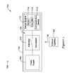
- FIG. 1 is a schematic diagram of an illustrative packaged sensor unit 100.
- Illustrative packaged sensor unit is generally shown at 100, and may include a sealed enclosure 102. Substantially all components of the packaged sensor unit 100 may be housed in the interior 104 of the sealed enclosure 102, save for the sealed enclosure itself. Sealed enclosure 102 may substantially or effectively seal its interior 104 from the exterior environment 106. Sealing may include preventing the contact and/or exchange of fluids (liquids or gases) between the interior 104 of the sealed enclosure 102 and the exterior environment 106. In some illustrative embodiments, sealed enclosure 102 may electrically insulate interior 104 from exterior environment 106.
- packaged sensor unit 100 does not provide any conductive pathways between interior 104 and exterior environment 106.
- sealed enclosure 102 may be devoid of any external switches or any other components that could compromise the sealing integrity of the enclosure, such as by providing a pathway for contaminants to enter the interior 102.
- sealed enclosure 102 may provide shielding for electric and/or magnetic fields.
- sealed enclosure 102 may help thermally insulate between interior 104 and exterior environment 106.
- sealed enclosure 102 may substantially thermally conduct between interior 104 and exterior environment 106. It is contemplated that the sealed enclosure 102 may define exterior walls that provide an interface between the interior 104 and the exterior environment 106.
- Sealed enclosure 102 may be constructed of any suitable material, in any suitable manner.
- multiple enclosure elements may be bonded together during manufacture, with the bonding providing a final seal.
- multiple enclosure elements may be snap fit together, possibly with a gasket or like sealing member disposed between enclosure elements to provide sealing.
- a sealed enclosure 102 may be substantially rigid.
- a sealed enclosure 102 may be mechanically flexible, allowing a degree of deformation with applied mechanical force.
- packaged sensor unit 100 may include a power supply 108, such as an internal battery or other suitable energy storage device (e.g. a super capacitor, a fuel cell, etc.), an activation mechanism 110, and a sensor module 112.
- the sensor module 112 may include a sensor 114, a controller 116 operatively coupled to the sensor 114, and a communication device 118 operatively coupled to the controller 116.
- all components of power supply 108, activation mechanism 110, and sensor module 112 are disposed entirely within the interior 104 of sealed enclosure 102.
- a component such as sensor 114 of sensor module 112 may be disposed in, on, or through, or be integrated with, sealed enclosure 102 such that the sensor 114 may physically contact and/or sensingly communicate with the exterior environment 106.
- provisions for such external contact or communication may be achieved in such a way that does not compromise the seal between the interior 104 of the sealed enclosure 102 and the exterior environment 106.
- Sensor 114 may be any suitable sensor configured to measure any quantity of interest, such as temperature, pressure, humidity, flow rate, magnitude of an electric, magnetic, or electromagnetic field, position and/or movement (e.g. global positioning sensor, accelerometer or gyroscope), and the like.
- Communication device 118 may be configured to employ any suitable communication technologies and protocols, such as (but not limited to) infrared (IR), near-field communications (NFC), surface acoustic waves (SAW), radio-frequency identification (RFID), Bluetooth, WiFi, other RF standards, etc.
- Communication device 118 may be used to communicate sensor measurements to a measurement and/or control system.
- activation mechanism 110 may be capable of selectively coupling or connecting the internal power supply 108 to the sensor module 112.
- the selective coupling may be initiated from external of the sealed enclosure 102 as part of an activation sequence, as discussed in further detail herein.
- an activation sequence which may include detection of a pre-defined triggering stimulus 120 applied by one or more external agents 122
- both the sensor module 112 and the activation mechanism 110 may remain in an electronically inactive state. In such a state, the sensor module 112 and the activation mechanism 110 may draw no power from the power supply (battery) 108 of the packaged sensor unit.
- a component in an electronically inactive state may neither dissipate electrical power nor radiate electromagnetic radiation.
- FIG. 2 is a flowchart of an illustrative method 200 for initiating a packaged sensor unit such as that of Figure 1 or any other suitable packaged sensor unit.
- a pre-defined triggering stimulus 120 may be applied to the packaged sensor unit 100.
- the pre-defined triggering stimulus 120 may be applied by at least one external agent 122 (located external to the sealed enclosure 102).
- the pre-defined triggering stimulus 120 may be detected via the activation mechanism 110 of the packaged sensor unit.
- the activation mechanism may connect or couple the power supply 108 to the sensor module 112 such that the sensor module may draw power from the power supply and enter an electronically active state.
- the packaged sensor unit 100 Prior to detecting the pre-defined triggering stimulus 120, the packaged sensor unit 100 may be configured such that sensor module 112 draws no power from power supply 108. Alternatively, or in addition, the packaged sensor unit 100 may be configured such that activation mechanism 110 draws no power from power supply 108 prior to detecting the pre-defined triggering stimulus 120.
- the activation mechanism 110 may generally include or be the component that detects the pre-defined triggering stimulus 120, the structure of the activation mechanism may be linked to the pre-defined triggering stimulus.
- the activation mechanism 110 may include a switch, and the pre-defined triggering stimulus may include exerting a force that mechanically closes the switch, resulting in connecting the power supply 108 to the sensor module 112.
- the switch may be a magnetic switch, and the force may be a magnetic force.
- the step of applying the pre-defined triggering stimulus may include providing a magnetic field through the wall of the sealed enclosure 102.
- a coded magnetic key may be employed to provide a coded magnetic field that is keyed to a coded magnetic switch. That is, the activation mechanism may include a magnetic switch matched to the coded magnetic key, but this is not required. Other magnetically-actuated activation mechanisms are contemplated.
- the pre-defined triggering stimulus may include acceleration of the packaged sensor unit 100 in a pre-defined acceleration profile.
- the activation mechanism 110 may include a mechanical switch that closes when the packaged sensor unit 100 is subjected to the pre-defined acceleration profile.
- Such an acceleration profile may be produced, for example, by shaking, striking, jerking, or otherwise applying a predefined mechanical impulse to the packaged sensor unit.
- the activation mechanism 110 once activated, may irreversibly couple the power supply 108 to the sensor module 112.
- the internal battery 108 may be selectively disconnected from the sensor module 112 after it has been connected to the sensor module. Such selective disconnection may be facilitated by the activation mechanism 110, or by another mechanism (not illustrated) of the packaged sensor unit.
- a mechanical switch may be opened via application of an appropriate magnetic field, or by subjecting the packaged sensor unit to a suitable acceleration profile. The switch that opens may the same switch that closed previously to connect the internal battery 108 to the sensor module 112, or it may be a different switch or the like.
- the walls of the sealed enclosure 102 may be mechanically flexible, and the pre-defined triggering stimulus may include applying compression or tension to the sealed enclosure.
- the activation mechanism 110 may include a mechanical switch coupled to the walls of the sealed enclosure 102, or response to increased pressure inside the sealed enclosure 102, to detect the applied compression or tension.
- the pre-defined triggering stimulus does not include applying compression or tension to the sealed enclosure.
- the pre-defined triggering stimulus does not include the application of static force to the sealed sensor unit.
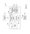
- FIG 3 is a schematic diagram of an illustrative packaged sensor unit 300 having an energy harvesting device 330. Some features of the illustrative packaged sensor unit 300 may be similar or identical to corresponding features of packaged sensor unit 100.
- Energy harvesting device 330 when supplied with harvestable energy 332, may harvest the harvestable energy 332 as part of an externally-initiated activation sequence. Harvested energy may be provided to the activation mechanism 310.
- Energy harvesting device 330 may include or be connected to an energy storage device, such as a battery, super-capacitor, etc., in the interior 304 of sealed enclosure 302.
- Energy provided by the energy harvesting device 330 may allow powered operation of the activation mechanism 310.
- a powered detector 334 may be used to detect a pre-defined triggering stimulus to result in the activation mechanism connecting power supply/internal battery 308 to sensor module 312, initiating the packaged sensor unit 300.
- powered detector 334 may be a dedicated device of the activation mechanism 310. It is contemplated in some other illustrative embodiments, however, that another device not solely purposed for detection of pre-defined triggering stimulus may be used, such as sensor 314 of the sensor module 312, or, one or more components of communication device 318. More generally, it is contemplated that any suitable device may be used as a powered detector 334.
- Detector 334 may be used to detect a pre-defined triggering stimulus, such as an electric and/or magnetic field, provided through the wall of the sealed enclosure 302.
- the pre-defined triggering stimulus may be a radio-frequency transmission employing a standard RF communication protocol.
- detector 334 may be an accelerometer suitable for detecting a pre-defined acceleration profile.
- a pre-defined triggering stimulus may come in the form of a type of measurand that the packaged sensor unit is tasked to measure and report.
- the activation mechanism 110, 310 draws no power from power supply 108, 308 prior to initiation of an activation sequence
- the activation mechanism may draw some power from the power supply prior to initiation of an activation sequence.
- Such power may be used, for example, to power a detector 334 or other sensor to detect a pre-defined triggering stimulus, or for any other suitable purpose.
- a packaged sensor unit with an activation mechanism that draws power from an internal power supply may have a shorter powered mission life than a packaged sensor unit with an activation mechanism that does not draw power from an internal power supply.
- energy provided by the energy harvesting device 330 may be used by the activation mechanism 310 to close an electronic switch or the like to connect the power supply/battery 308 to the sensor module 312.
- the harvested energy may be considered to have been used to connect the internal battery to the sensor module if any part of the process of making such a connection (such as detecting the pre-defined triggering stimulus) is performed using the harvested energy.
- Energy harvesting device 330 may be any suitable device capable of harvesting any suitable harvestable energy 332.
- the energy harvesting device 330 may harvest one or more of thermal energy, mechanical energy, optical energy, electromagnetic energy, or other energy.
- the step of providing harvestable energy may include, for example, exposing the packaged sensor unit 300 to a temperature difference or differential; translating, rotating, or otherwise subjecting the packaged sensor unit 300 to motion; exposing the packaged sensor unit 300 to light (the packaged sensor unit may be shielded from light until activation); subjecting the packaged sensor unit 300 to a time-varying electromagnetic field; and so on.
- the energy harvesting device 330 may convert the harvested energy into electrical energy, but conversion to other forms of energy, which may be stored, is also contemplated in some embodiments.
- the act of providing harvestable energy itself may be the act of providing the pre-defined triggering stimulus to the sensor unit. Harvesting a sufficient amount of energy may trigger the activation mechanism 310, which may then connect the internal power supply to the sensor module. In some cases, the activation mechanism 310, once activated, may irreversibly couple the power supply 308 to the sensor module 312.
- a packaged sensor unit 300 includes an energy harvesting device 304, and the activation mechanism 310 requires power from the energy harvesting device 330 to couple the internal power supply 308 to the sensor module 312 to activate the sensor module 312.
- a sensor module 312 of a packaged sensor unit 300 may use energy harvested by an energy harvesting device 330, but this is not required.
- Initiation or activation of a packaged sensor unit may include the step of commissioning the sensor unit and/or sensor module. Commissioning may include any steps that facilitate the use of the packaged sensor unit in the field. In some cases, commissioning may be necessary for the packaged sensor unit to be used by a measurement and/or control system. In other cases, commissioning may not be required at all. Commissioning may include, for example, establishing communication protocols between the packaged sensor unit and external devices, which may include secure communications; calibration of one or more sensors of the packaged sensor unit; download or other specification of configuration parameters to the packaged sensor unit, and the like. Bulk commissioning of more than one packaged sensor unit during a commissioning session may be performed.
- multiple packaged sensor units may share one or more security keys.
- packaged sensor units may have unique security keys.
- Commissioning may be accomplished by any suitable protocol. Any suitable communications means may be employed for commissioning, including but not limited to IR, NFC, SAW, RFID, Bluetooth, WiFi, other RF standards, etc.
- the communication device (e.g., 118/318) of a sensor module may be used for commissioning, or other hardware of the packaged sensor unit may be employed.
- commissioning may be performed subsequent to the step of connecting the internal battery to the sensor module.
- commissioning may be performed prior to the step of connecting the internal battery to the sensor module. Such prior commissioning may be performed, for example, at a factory with the sensor module powered-up, then the sensor module may be powered-down for transport, storage, etc. until subsequent powering-up in the field via one or more methods of the present disclosure.
- FIG 4 is a flowchart of another illustrative method 400 for initiating a packaged sensor unit, such as packaged sensor unit 300 of Figure 3 .
- the packaged sensor unit optionally may be pre-commissioned, for example, at a factory.
- harvestable energy may be provided to the packaged sensor unit.
- the energy harvesting device of the packaged sensor unit (if so equipped) may harvest the harvestable energy.
- a pre-defined triggering stimulus may be applied to the packaged sensor unit.
- the pre-defined triggering stimulus may be detected by the activation mechanism of the packaged sensor unit; if an energy harvesting device is present, the activation mechanism may use harvested energy.
- the internal battery (power supply) of the packaged sensor unit maybe connected to the sensor module.
- the packaged sensor unit may be commissioned, if needed or desired.
- the internal battery may optionally be selectively disconnected from the sensor module. In some cases, the internal battery (power supply) may be irreversibly coupled to the sensor module.
Abstract
Description
- The disclosure relates generally to sensors, and more particular, to systems and methods for activating sensors in the field.
- Wireless sensors have demonstrated their value in recent times. Wireless sensors may be used to measure and report a variety of quantities, such as pressure, temperature, position, acoustic output, and other quantities that may be suitably measured. Wireless sensors may be employed in HVAC systems, industrial process monitoring and control, and many other applications.
- Wireless sensors may be packaged in sealed enclosures for a number of reasons, including cost reduction and protection of the sensor from the environment. Enclosing sensors in sealed packages can raise operational issues in the field. The present disclosure, among various aspects, provides for initiation of sensors that are packaged in sealed enclosures.
- The disclosure relates generally to sensors, and more particular, to systems and methods for initiating sealed sensors in the field. In an illustrative but non-limiting example, a method for initiating a packaged sensor unit is provided. The packaged sensor unit may include a sensor module, an activation mechanism, and an internal battery, all situated in a sealed enclosure. The method may include applying a pre-defined triggering stimulus to the packaged sensor unit, and detecting the pre-defined triggering stimulus via the activation mechanism of the packaged sensor unit. When the activation mechanism detects the pre-defined triggering stimulus, the internal battery may be connected to the sensor module. Prior to detecting the pre-defined triggering stimulus, both the sensor module and the activation mechanism may draw no power from the internal battery of the packaged sensor unit. This may increase the shelf-life of the packaged sensor unit before the packaged sensor unit is deployed in the field.
- In another illustrative but non-limiting example, a packaged sensor unit is provided. The packaged sensor unit may include a sensor module having sensor, a controller operatively coupled to the sensor, and a communication device operatively coupled to the controller. The packaged sensor unit may also include a power supply, an activation mechanism capable of selectively coupling the power supply to the sensor module, and a sealed enclosure housing the sensor module, the power supply, and the activation mechanism. In some cases, the sealed enclosure may be devoid of any external switch. In some instances, the packaged sensor unit may be configured such that the sensor module and the activation mechanism remain in an electronically inactive state until an activation sequence is externally initiated. In an electronically inactive state, the sensor module and activation may, for example, draw no power from the power supply of the packaged sensor unit. In some instances, an energy harvesting device may be included in the packaged sensor unit, which may harvest energy provided to the packaged sensor unit. The activation mechanism may use the harvested energy.
- The above summary is not intended to describe each and every disclosed illustrative example or every implementation of the disclosure. The Description that follows more particularly exemplifies various illustrative embodiments.
- The following description should be read with reference to the drawings. The drawings, which are not necessarily to scale, depict selected illustrative embodiments and are not intended to limit the scope of the disclosure. The disclosure may be more completely understood in consideration of the following detailed description of various illustrative embodiments in connection with the accompanying drawings, in which:
-
Figure 1 is a schematic diagram of an illustrative packaged sensor unit; -
Figure 2 is a flowchart of an illustrative method for initiating a packaged sensor unit; -
Figure 3 is a schematic diagram of an illustrative packaged sensor unit having an energy harvesting device; and -
Figure 4 is a flowchart of another illustrative method for initiating a packaged sensor unit. - The following description should be read with reference to the drawings, in which like elements in different drawings are numbered in like fashion. The drawings, which are not necessarily to scale, depict selected illustrative embodiments and are not intended to limit the scope of the disclosure. Although examples of construction, dimensions, and materials are illustrated for the various elements, those skilled in the art will recognize that many of the examples provided have suitable alternatives that may be utilized.
- Wireless sensors typically operate on power provided by an internal or onboard power source, such as a battery. While it is possible that a wireless sensor may be shipped from a factory in a powered-on state, often such sensors are shipped powered-down. By shipping powered-down, battery drain may be avoided prior to deployment of the wireless sensor, and in some cases, it may be desirable or required (due to regulations, for example) that a wireless sensor not emit radio-frequency or other signals during transit. Some wireless sensors that ship unpowered may be powered-up in a number of ways, such as upon insertion of a battery, closing of an externally accessible switch, or some other application of power.
- In some illustrative embodiments of the present disclosure, a sensor unit may be packaged in a sealed enclosure or package. A sealed enclosure may be an enclosure that prevents contact between the internal volume inside the enclosure with the external environment outside the enclosure. In some cases, a sealed enclosure, once sealed at the factory, may not be opened or unsealed without irreversibly damaging the ability of the enclosure to seal. In other words, an irreversibly sealed enclosure or package may be permanently sealed upon completion of manufacture, and may not be unsealed or opened before the end-of-life of the sensor unit. In some other cases, it may be possible to open, then reseal a sealed enclosure. In some cases, it may be impractical or cost-prohibitive to re-seal a previously sealed enclosure, once opened.
- A sealed enclosure may be employed for cost reduction, as the cost of screws, threading, etc. may be avoided. Also, a sealed enclosure may be suitable for use in hazardous environments, such as in the presence of explosive gases, where the sealed enclosure may prevent or reduce possibility of contact between the explosive gas and potentially hazardous potentials and/or currents originating from within the enclosure. In addition or alternately, a sealed enclosure may protect the sensor unit itself from moisture, corrosive fluids (including liquid and/or gases), etc., of the environment in which the package is deployed, or through which the package is transported, etc.
- Use of a sealed enclosure or package may prevent using some methods of powering-up a wireless sensor. For example, it may not be possible to insert a battery to power-up a sensor unit in the field. Many mechanically-actuated switches, which might otherwise be made accessible from the exterior of a sealed enclosure and employed to turn on power for the sensor unit in the field, may not be usable with a sealed enclosure due to the difficulty or impossibility of sealing the enclosure with such a switch present.
-
Figure 1 is a schematic diagram of an illustrative packagedsensor unit 100. Illustrative packaged sensor unit is generally shown at 100, and may include a sealedenclosure 102. Substantially all components of the packagedsensor unit 100 may be housed in theinterior 104 of the sealedenclosure 102, save for the sealed enclosure itself. Sealedenclosure 102 may substantially or effectively seal itsinterior 104 from theexterior environment 106. Sealing may include preventing the contact and/or exchange of fluids (liquids or gases) between theinterior 104 of the sealedenclosure 102 and theexterior environment 106. In some illustrative embodiments, sealedenclosure 102 may electrically insulateinterior 104 fromexterior environment 106. In some illustrative embodiments, packagedsensor unit 100 does not provide any conductive pathways between interior 104 andexterior environment 106. In some illustrative embodiments, sealedenclosure 102 may be devoid of any external switches or any other components that could compromise the sealing integrity of the enclosure, such as by providing a pathway for contaminants to enter theinterior 102. In some illustrative embodiments, sealedenclosure 102 may provide shielding for electric and/or magnetic fields. In some illustrative embodiments, sealedenclosure 102 may help thermally insulate between interior 104 andexterior environment 106. In some illustrative embodiments, sealedenclosure 102 may substantially thermally conduct betweeninterior 104 andexterior environment 106. It is contemplated that the sealedenclosure 102 may define exterior walls that provide an interface between the interior 104 and theexterior environment 106. -
Sealed enclosure 102 may be constructed of any suitable material, in any suitable manner. For example, in some illustrative embodiments, multiple enclosure elements may be bonded together during manufacture, with the bonding providing a final seal. In some illustrative embodiments, multiple enclosure elements may be snap fit together, possibly with a gasket or like sealing member disposed between enclosure elements to provide sealing. In some illustrative embodiments, a sealedenclosure 102 may be substantially rigid. In other illustrative embodiments, a sealedenclosure 102 may be mechanically flexible, allowing a degree of deformation with applied mechanical force. - As shown in
Figure 1 , packagedsensor unit 100 may include apower supply 108, such as an internal battery or other suitable energy storage device (e.g. a super capacitor, a fuel cell, etc.), anactivation mechanism 110, and asensor module 112. Thesensor module 112 may include asensor 114, acontroller 116 operatively coupled to thesensor 114, and acommunication device 118 operatively coupled to thecontroller 116. In some illustrative embodiments, all components ofpower supply 108,activation mechanism 110, andsensor module 112 are disposed entirely within theinterior 104 of sealedenclosure 102. In some illustrative embodiments, a component such assensor 114 ofsensor module 112 may be disposed in, on, or through, or be integrated with, sealedenclosure 102 such that thesensor 114 may physically contact and/or sensingly communicate with theexterior environment 106. Generally, provisions for such external contact or communication may be achieved in such a way that does not compromise the seal between the interior 104 of the sealedenclosure 102 and theexterior environment 106. -
Sensor 114 may be any suitable sensor configured to measure any quantity of interest, such as temperature, pressure, humidity, flow rate, magnitude of an electric, magnetic, or electromagnetic field, position and/or movement (e.g. global positioning sensor, accelerometer or gyroscope), and the like.Communication device 118 may be configured to employ any suitable communication technologies and protocols, such as (but not limited to) infrared (IR), near-field communications (NFC), surface acoustic waves (SAW), radio-frequency identification (RFID), Bluetooth, WiFi, other RF standards, etc.Communication device 118 may be used to communicate sensor measurements to a measurement and/or control system. - As schematically represented in
Figure 1 with the use of the symbol for a switch,activation mechanism 110 may be capable of selectively coupling or connecting theinternal power supply 108 to thesensor module 112. The selective coupling may be initiated from external of the sealedenclosure 102 as part of an activation sequence, as discussed in further detail herein. Prior to the activation sequence, which may include detection of a pre-defined triggeringstimulus 120 applied by one or moreexternal agents 122, both thesensor module 112 and theactivation mechanism 110 may remain in an electronically inactive state. In such a state, thesensor module 112 and theactivation mechanism 110 may draw no power from the power supply (battery) 108 of the packaged sensor unit. In some illustrative embodiments, a component in an electronically inactive state may neither dissipate electrical power nor radiate electromagnetic radiation. -
Figure 2 is a flowchart of anillustrative method 200 for initiating a packaged sensor unit such as that ofFigure 1 or any other suitable packaged sensor unit. Atstep 210, a pre-defined triggeringstimulus 120 may be applied to the packagedsensor unit 100. The pre-defined triggeringstimulus 120 may be applied by at least one external agent 122 (located external to the sealed enclosure 102). Atstep 220, the pre-defined triggeringstimulus 120 may be detected via theactivation mechanism 110 of the packaged sensor unit. In response to theactivation mechanism 110 detecting the pre-defined triggeringstimulus 120, the activation mechanism may connect or couple thepower supply 108 to thesensor module 112 such that the sensor module may draw power from the power supply and enter an electronically active state. Prior to detecting the pre-defined triggeringstimulus 120, the packagedsensor unit 100 may be configured such thatsensor module 112 draws no power frompower supply 108. Alternatively, or in addition, the packagedsensor unit 100 may be configured such thatactivation mechanism 110 draws no power frompower supply 108 prior to detecting the pre-defined triggeringstimulus 120. - As the
activation mechanism 110 may generally include or be the component that detects the pre-defined triggeringstimulus 120, the structure of the activation mechanism may be linked to the pre-defined triggering stimulus. For example, theactivation mechanism 110 may include a switch, and the pre-defined triggering stimulus may include exerting a force that mechanically closes the switch, resulting in connecting thepower supply 108 to thesensor module 112. In some illustrative embodiments, the switch may be a magnetic switch, and the force may be a magnetic force. The step of applying the pre-defined triggering stimulus may include providing a magnetic field through the wall of the sealedenclosure 102. In some such cases, a coded magnetic key may be employed to provide a coded magnetic field that is keyed to a coded magnetic switch. That is, the activation mechanism may include a magnetic switch matched to the coded magnetic key, but this is not required. Other magnetically-actuated activation mechanisms are contemplated. - In some illustrative embodiments, the pre-defined triggering stimulus may include acceleration of the packaged
sensor unit 100 in a pre-defined acceleration profile. In such an embodiment, theactivation mechanism 110 may include a mechanical switch that closes when the packagedsensor unit 100 is subjected to the pre-defined acceleration profile. Such an acceleration profile may be produced, for example, by shaking, striking, jerking, or otherwise applying a predefined mechanical impulse to the packaged sensor unit. - In some illustrative embodiments, the
activation mechanism 110, once activated, may irreversibly couple thepower supply 108 to thesensor module 112. In some other illustrative embodiments, theinternal battery 108 may be selectively disconnected from thesensor module 112 after it has been connected to the sensor module. Such selective disconnection may be facilitated by theactivation mechanism 110, or by another mechanism (not illustrated) of the packaged sensor unit. For example, a mechanical switch may be opened via application of an appropriate magnetic field, or by subjecting the packaged sensor unit to a suitable acceleration profile. The switch that opens may the same switch that closed previously to connect theinternal battery 108 to thesensor module 112, or it may be a different switch or the like. - In some illustrative embodiments, at least some of the walls of the sealed
enclosure 102 may be mechanically flexible, and the pre-defined triggering stimulus may include applying compression or tension to the sealed enclosure. Theactivation mechanism 110 may include a mechanical switch coupled to the walls of the sealedenclosure 102, or response to increased pressure inside the sealedenclosure 102, to detect the applied compression or tension. In some illustrative embodiments, the pre-defined triggering stimulus does not include applying compression or tension to the sealed enclosure. In some illustrative embodiments, the pre-defined triggering stimulus does not include the application of static force to the sealed sensor unit. -
Figure 3 is a schematic diagram of an illustrative packagedsensor unit 300 having anenergy harvesting device 330. Some features of the illustrative packagedsensor unit 300 may be similar or identical to corresponding features of packagedsensor unit 100.Energy harvesting device 330, when supplied withharvestable energy 332, may harvest theharvestable energy 332 as part of an externally-initiated activation sequence. Harvested energy may be provided to theactivation mechanism 310.Energy harvesting device 330 may include or be connected to an energy storage device, such as a battery, super-capacitor, etc., in theinterior 304 of sealedenclosure 302. - Energy provided by the
energy harvesting device 330 may allow powered operation of theactivation mechanism 310. For example, in some illustrative embodiments, apowered detector 334 may be used to detect a pre-defined triggering stimulus to result in the activation mechanism connecting power supply/internal battery 308 tosensor module 312, initiating the packagedsensor unit 300. In some cases,powered detector 334 may be a dedicated device of theactivation mechanism 310. It is contemplated in some other illustrative embodiments, however, that another device not solely purposed for detection of pre-defined triggering stimulus may be used, such assensor 314 of thesensor module 312, or, one or more components ofcommunication device 318. More generally, it is contemplated that any suitable device may be used as apowered detector 334.Detector 334 may be used to detect a pre-defined triggering stimulus, such as an electric and/or magnetic field, provided through the wall of the sealedenclosure 302. In some embodiments, the pre-defined triggering stimulus may be a radio-frequency transmission employing a standard RF communication protocol. In some embodiments,detector 334 may be an accelerometer suitable for detecting a pre-defined acceleration profile. In some illustrative embodiments, a pre-defined triggering stimulus may come in the form of a type of measurand that the packaged sensor unit is tasked to measure and report. - While in some embodiments, the
activation mechanism power supply detector 334 or other sensor to detect a pre-defined triggering stimulus, or for any other suitable purpose. A packaged sensor unit with an activation mechanism that draws power from an internal power supply may have a shorter powered mission life than a packaged sensor unit with an activation mechanism that does not draw power from an internal power supply. - Aside from powered detection of pre-defined triggering stimuli, energy provided by the
energy harvesting device 330 may be used by theactivation mechanism 310 to close an electronic switch or the like to connect the power supply/battery 308 to thesensor module 312. In a more general sense, the harvested energy may be considered to have been used to connect the internal battery to the sensor module if any part of the process of making such a connection (such as detecting the pre-defined triggering stimulus) is performed using the harvested energy. -
Energy harvesting device 330 may be any suitable device capable of harvesting any suitableharvestable energy 332. Theenergy harvesting device 330 may harvest one or more of thermal energy, mechanical energy, optical energy, electromagnetic energy, or other energy. The step of providing harvestable energy may include, for example, exposing the packagedsensor unit 300 to a temperature difference or differential; translating, rotating, or otherwise subjecting the packagedsensor unit 300 to motion; exposing the packagedsensor unit 300 to light (the packaged sensor unit may be shielded from light until activation); subjecting the packagedsensor unit 300 to a time-varying electromagnetic field; and so on. Theenergy harvesting device 330 may convert the harvested energy into electrical energy, but conversion to other forms of energy, which may be stored, is also contemplated in some embodiments. - In some illustrative embodiments, the act of providing harvestable energy itself may be the act of providing the pre-defined triggering stimulus to the sensor unit. Harvesting a sufficient amount of energy may trigger the
activation mechanism 310, which may then connect the internal power supply to the sensor module. In some cases, theactivation mechanism 310, once activated, may irreversibly couple thepower supply 308 to thesensor module 312. - In some illustrative embodiments, a packaged
sensor unit 300 includes anenergy harvesting device 304, and theactivation mechanism 310 requires power from theenergy harvesting device 330 to couple theinternal power supply 308 to thesensor module 312 to activate thesensor module 312. In some illustrative embodiments, asensor module 312 of a packagedsensor unit 300 may use energy harvested by anenergy harvesting device 330, but this is not required. - Initiation or activation of a packaged sensor unit, which may include initiation or activation of a sensor module of the packaged sensor unit, may include the step of commissioning the sensor unit and/or sensor module. Commissioning may include any steps that facilitate the use of the packaged sensor unit in the field. In some cases, commissioning may be necessary for the packaged sensor unit to be used by a measurement and/or control system. In other cases, commissioning may not be required at all. Commissioning may include, for example, establishing communication protocols between the packaged sensor unit and external devices, which may include secure communications; calibration of one or more sensors of the packaged sensor unit; download or other specification of configuration parameters to the packaged sensor unit, and the like. Bulk commissioning of more than one packaged sensor unit during a commissioning session may be performed. In some illustrative embodiments, multiple packaged sensor units may share one or more security keys. In some illustrative embodiments, packaged sensor units may have unique security keys. Commissioning may be accomplished by any suitable protocol. Any suitable communications means may be employed for commissioning, including but not limited to IR, NFC, SAW, RFID, Bluetooth, WiFi, other RF standards, etc. The communication device (e.g., 118/318) of a sensor module may be used for commissioning, or other hardware of the packaged sensor unit may be employed. In some illustrative embodiments, commissioning may be performed subsequent to the step of connecting the internal battery to the sensor module. In some illustrative embodiments, commissioning may be performed prior to the step of connecting the internal battery to the sensor module. Such prior commissioning may be performed, for example, at a factory with the sensor module powered-up, then the sensor module may be powered-down for transport, storage, etc. until subsequent powering-up in the field via one or more methods of the present disclosure.
-
Figure 4 is a flowchart of anotherillustrative method 400 for initiating a packaged sensor unit, such as packagedsensor unit 300 ofFigure 3 . At 410, the packaged sensor unit optionally may be pre-commissioned, for example, at a factory. At 420, harvestable energy may be provided to the packaged sensor unit. At 430, the energy harvesting device of the packaged sensor unit (if so equipped) may harvest the harvestable energy. At 440, a pre-defined triggering stimulus may be applied to the packaged sensor unit. At 450, the pre-defined triggering stimulus may be detected by the activation mechanism of the packaged sensor unit; if an energy harvesting device is present, the activation mechanism may use harvested energy. At 460, following detection of the pre-defined triggering stimulus, the internal battery (power supply) of the packaged sensor unit maybe connected to the sensor module. At 470, the packaged sensor unit may be commissioned, if needed or desired. At 480, the internal battery may optionally be selectively disconnected from the sensor module. In some cases, the internal battery (power supply) may be irreversibly coupled to the sensor module. - The disclosure should not be considered limited to the particular examples described above. Various modifications, equivalent processes, as well as numerous structures to which the disclosure can be applicable will be readily apparent to those of skill in the art upon review of the instant specification.
Claims (15)
- A method for initiating a packaged sensor unit (100) having a sealed enclosure (102), the sensor unit (100) including a sensor module (112), an activation mechanism (110), and an internal battery (108) all in the sealed enclosure (102), the method comprising:applying a pre-defined triggering stimulus (120) to the packaged sensor unit (100);detecting the pre-defined triggering stimulus (120) via the activation mechanism (110);connecting the internal battery (108) to the sensor module (112) in response to the activation mechanism (110) detecting the pre-defined triggering stimulus (120); andwherein prior to detecting the pre-defined triggering stimulus (120), both the sensor module (112) and the activation mechanism (110) draw no power from the internal battery (108) of the packaged sensor unit (100).
- The method of claim 1, wherein the step of applying the pre-defined triggering stimulus (120) includes providing an electric and/or magnetic field through a wall of the sealed enclosure (102).
- The method of claim 2, wherein the step of applying the pre-defined triggering stimulus (120) includes providing a magnetic field through the wall of the sealed enclosure (102).
- The method of claim 3, wherein a coded magnetic key is employed to provide the magnetic field.
- The method of claim 1, wherein the step of applying the pre-defined triggering stimulus (120) includes accelerating the packaged sensor unit (100) in a pre-defined acceleration profile.
- The method of claim 5, wherein the activation mechanism (110) includes an accelerometer.
- The method of claim 1, wherein:the activation mechanism (110) includes a switch; andthe pre-defined triggering stimulus (120) includes exerting a force that mechanically closes the switch, resulting in connecting the internal battery (108) to the sensor module (112).
- The method of claim 7, wherein the switch is a magnetic switch, and the force is a magnetic force.
- The method of claim 1, wherein:the activation mechanism (110) includes an energy harvesting device (304); the method further includes the steps of:providing harvestable energy (332) to the sensor unit (100) through the wall of the sealed enclosure (102);the energy harvesting device (304) harvesting the harvestable energy (332), and then using the harvestable energy (332) to connect the internal battery (108) to the sensor module (112).
- The method of claim 9, wherein the energy harvesting device (304) harvests one or more of thermal energy, mechanical energy, optical energy and electromagnetic energy.
- The method of claim 1, further comprising the step of commissioning the packaged sensor unit (100) subsequent to the step of connecting the internal battery (108) to the sensor module (112).
- The method of claim 1, further comprising the step of pre-commissioning the packaged sensor unit (100) prior to the step of connecting the internal battery (108) to the sensor module (112).
- The method of claim 1, further comprising the step of selectively disconnecting the internal battery (108) from the sensor module (112) after the step of connecting the internal battery (108) to the sensor module (112).
- The method of claim 1, wherein the connecting step is irreversible.
- A packaged sensor unit (100), comprising:a sensor module (112) including:a sensor (114);a controller (116) operatively coupled to the sensor (114); anda communication device (118) operatively coupled to the controller (116); a power supply (108);an activation mechanism (110) capable of selectively coupling the power supply (108) to the sensor module (112);a sealed enclosure (102) housing the sensor module (112), the power supply (108), and the activation mechanism (110), the sealed enclosure (102) being devoid of any external switch;wherein:the packaged sensor unit (100) is configured such that the sensor module (112) and the activation mechanism (110) remain in an electronically inactive state until an activation sequence is externally initiated.
Applications Claiming Priority (1)
| Application Number | Priority Date | Filing Date | Title |
|---|---|---|---|
| US13/161,364 US10018487B2 (en) | 2011-06-15 | 2011-06-15 | Methods and systems for activating sealed sensors in the field |
Publications (3)
| Publication Number | Publication Date |
|---|---|
| EP2535687A2 true EP2535687A2 (en) | 2012-12-19 |
| EP2535687A3 EP2535687A3 (en) | 2017-05-17 |
| EP2535687B1 EP2535687B1 (en) | 2018-07-11 |
Family
ID=46210105
Family Applications (1)
| Application Number | Title | Priority Date | Filing Date |
|---|---|---|---|
| EP12169673.6A Active EP2535687B1 (en) | 2011-06-15 | 2012-05-25 | Methods and systems for activating sealed sensors in the field |
Country Status (4)
| Country | Link |
|---|---|
| US (1) | US10018487B2 (en) |
| EP (1) | EP2535687B1 (en) |
| CN (2) | CN102829814B (en) |
| CA (1) | CA2778542A1 (en) |
Cited By (1)
| Publication number | Priority date | Publication date | Assignee | Title |
|---|---|---|---|---|
| WO2016139049A1 (en) * | 2015-03-02 | 2016-09-09 | Endress+Hauser Gmbh+Co. Kg | Field device for automation engineering |
Families Citing this family (4)
| Publication number | Priority date | Publication date | Assignee | Title |
|---|---|---|---|---|
| US10018487B2 (en) | 2011-06-15 | 2018-07-10 | Honeywell International Inc. | Methods and systems for activating sealed sensors in the field |
| US20140138275A1 (en) * | 2012-11-20 | 2014-05-22 | Nokia Corporation | Automatic power-up from sales package |
| DE102018212965A1 (en) * | 2018-08-02 | 2020-02-06 | Vega Grieshaber Kg | BATTERY POWERED MEASURING DEVICE |
| US11094486B2 (en) | 2018-12-20 | 2021-08-17 | Cognex Corporation | Magnetic trigger arrangement |
Family Cites Families (36)
| Publication number | Priority date | Publication date | Assignee | Title |
|---|---|---|---|---|
| US5301553A (en) | 1989-12-20 | 1994-04-12 | Tjs Development Corporation | Apparatus for remote sensing and receiving |
| DE19619975C1 (en) * | 1996-05-17 | 1997-09-11 | Daimler Benz Ag | Hand transmitter operating method for vehicle remote control |
| US5908365A (en) * | 1997-02-05 | 1999-06-01 | Preeminent Energy Services, Inc. | Downhole triggering device |
| US6298787B1 (en) * | 1999-10-05 | 2001-10-09 | Southwest Research Institute | Non-lethal kinetic energy weapon system and method |
| US6351906B1 (en) * | 1999-11-05 | 2002-03-05 | Ernest M. Honig, Jr. | Firearm automatic locking system and method |
| US7478108B2 (en) * | 1999-12-06 | 2009-01-13 | Micro Strain, Inc. | Data collection using sensing units and separate control units with all power derived from the control units |
| US8384538B2 (en) * | 2002-06-11 | 2013-02-26 | Intelligent Technologies International, Inc. | Remote monitoring of fixed structures |
| US6991257B2 (en) * | 2003-03-14 | 2006-01-31 | Ford Global Technologies, Llc | Side airbag for a vehicle |
| US20050246040A1 (en) * | 2004-04-29 | 2005-11-03 | Caterpillar Inc. | Operator profile control system for a work machine |
| WO2005122879A1 (en) | 2004-06-15 | 2005-12-29 | Philips Intellectual Property & Standards Gmbh | Sensor for acquiring physiological signals of a patient |
| US7236072B2 (en) * | 2004-12-01 | 2007-06-26 | Teledyne Technologies Incorporated | Passive magnetic latch |
| GB0502886D0 (en) | 2005-02-11 | 2005-03-16 | Univ Glasgow | Sensing device and system |
| US7117129B1 (en) | 2005-03-11 | 2006-10-03 | Hewlett-Packard Development Company, L.P. | Commissioning of sensors |
| US7629545B1 (en) * | 2005-06-02 | 2009-12-08 | Asner Jerome L | Impact-activated trigger with omni-directional sensor |
| WO2007100343A1 (en) | 2005-06-03 | 2007-09-07 | Terahop Networks Inc. | Remote sensor interface (rsi) stepped wake-up sequence |
| NO20053351A (en) | 2005-07-11 | 2007-01-08 | Hovden Knut Reinhardt | Motion-activated device |
| US7551087B2 (en) | 2005-08-19 | 2009-06-23 | Adasa, Inc. | Handheld and cartridge-fed applicator for commissioning wireless sensors |
| US7351066B2 (en) * | 2005-09-26 | 2008-04-01 | Apple Computer, Inc. | Electromagnetic connector for electronic device |
| US7675935B2 (en) | 2006-05-31 | 2010-03-09 | Honeywell International Inc. | Apparatus and method for integrating wireless or other field devices in a process control system |
| JP4881095B2 (en) * | 2006-07-28 | 2012-02-22 | 株式会社東海理化電機製作所 | Key system |
| JP4995513B2 (en) * | 2006-08-29 | 2012-08-08 | セイコーインスツル株式会社 | Pedometer |
| GB0704878D0 (en) | 2007-03-14 | 2007-04-18 | Trw Ltd | Aircraft landing gear monitoring apparatus |
| GB2448861A (en) * | 2007-05-04 | 2008-11-05 | Tana Leonardus Wondergem | Light switch controlled socket isolator |
| CN100507452C (en) | 2007-06-01 | 2009-07-01 | 北京中星微电子有限公司 | Sensor interface signal conversion device and method |
| US7993224B2 (en) * | 2007-10-10 | 2011-08-09 | Grace Engineering Corp. | Battery holder for a lighted archery nock |
| US20090108814A1 (en) * | 2007-10-24 | 2009-04-30 | Christopher Wilkins | Battery Switch Sensor |
| US20090121550A1 (en) * | 2007-11-12 | 2009-05-14 | Louis Riviera | Universal Power Adapter |
| US20090317028A1 (en) * | 2008-06-24 | 2009-12-24 | Larry Castleman | Seal assembly in situ lifetime measurement |
| US20100013639A1 (en) * | 2008-07-21 | 2010-01-21 | Rene Revert | Low power asset position tracking system |
| US8224576B2 (en) | 2008-10-21 | 2012-07-17 | Paksense, Inc. | Environmental sensing and communication |
| US8258959B2 (en) * | 2008-12-31 | 2012-09-04 | L3 Communications Integrated Systems, L.P. | Activation circuit for sealed electronic device |
| US8692648B2 (en) * | 2009-11-02 | 2014-04-08 | Snap-On Tools Of Canada, Ltd. | System for monitoring and/or controlling equipment in a hazardous area |
| US8928190B2 (en) * | 2009-12-31 | 2015-01-06 | Ultralife Corporation | System and method for activating an isolated device |
| CN101873587B (en) * | 2010-05-27 | 2013-06-26 | 大唐微电子技术有限公司 | Wireless communication device and method for realizing service security thereof |
| US20120119681A1 (en) * | 2010-11-15 | 2012-05-17 | Raffel Systems, Llc | Light devices and systems |
| US10018487B2 (en) | 2011-06-15 | 2018-07-10 | Honeywell International Inc. | Methods and systems for activating sealed sensors in the field |
-
2011
- 2011-06-15 US US13/161,364 patent/US10018487B2/en active Active
-
2012
- 2012-05-25 EP EP12169673.6A patent/EP2535687B1/en active Active
- 2012-05-31 CA CA 2778542 patent/CA2778542A1/en not_active Abandoned
- 2012-06-14 CN CN201210195840.9A patent/CN102829814B/en not_active Expired - Fee Related
- 2012-06-14 CN CN201610888091.6A patent/CN107014422B/en not_active Expired - Fee Related
Non-Patent Citations (1)
| Title |
|---|
| None |
Cited By (2)
| Publication number | Priority date | Publication date | Assignee | Title |
|---|---|---|---|---|
| WO2016139049A1 (en) * | 2015-03-02 | 2016-09-09 | Endress+Hauser Gmbh+Co. Kg | Field device for automation engineering |
| US10264691B2 (en) | 2015-03-02 | 2019-04-16 | Endress+Hauser SE+Co. KG | Field device for automation technology |
Also Published As
| Publication number | Publication date |
|---|---|
| CA2778542A1 (en) | 2012-12-15 |
| US10018487B2 (en) | 2018-07-10 |
| US20120319482A1 (en) | 2012-12-20 |
| CN102829814B (en) | 2016-12-21 |
| CN107014422B (en) | 2020-07-24 |
| EP2535687A3 (en) | 2017-05-17 |
| CN107014422A (en) | 2017-08-04 |
| CN102829814A (en) | 2012-12-19 |
| EP2535687B1 (en) | 2018-07-11 |
Similar Documents
| Publication | Publication Date | Title |
|---|---|---|
| US10018487B2 (en) | Methods and systems for activating sealed sensors in the field | |
| EP2294364B1 (en) | Wireless communication adapter for field devices | |
| US9674976B2 (en) | Wireless process communication adapter with improved encapsulation | |
| JP5031842B2 (en) | Wireless field device with antenna and radome for industrial location | |
| US8626087B2 (en) | Wire harness for field devices used in a hazardous locations | |
| EP2805142B1 (en) | Field device with self-testing of a piezoelectric transducer | |
| RU2636814C2 (en) | Process variable transmitter with cabin with two branches | |
| US20140077816A1 (en) | Sensor device and method for producing a sensor device for accommodation in a galvanic cell | |
| EP2972115B1 (en) | Wireless interface within transmitter | |
| CN115023594A (en) | Temperature indicator | |
| KR102165219B1 (en) | Speed sensor | |
| CN103959017A (en) | Sensor module with a displacement sensor and a pressure sensor in a common housing | |
| JP2016508603A (en) | Sensor with modular threaded package | |
| EP3049764B1 (en) | Process variable transmitter with dual compartment housing | |
| CN114829881A (en) | Sensor device, management system, management server, acceptance check device, method executed by sensor device, and label | |
| CN105992480B (en) | Controller | |
| US10989732B2 (en) | Wireless piezoelectric accelerometer and system | |
| AU2019904454A0 (en) | A small individual miniature re-programmable computer system, energized via passive/active or positive energy source exceeding explosive environments IP protocols, unit for onboard data mining detection sensor/s capture values and ranging analysis monitoring of any environmental factors and interrogation transceiver remote scanning and integrated with any of the following features of temperature, vibration, noise, stress, breaker bar or load cell/s, volume/s, degradation, contamination, electrical induction or any other feature monitoring array of values. | |
| WO2013150485A2 (en) | Method and device for measuring and collecting environment data in a closed volume | |
| CN114981851A (en) | Sensor device and expansion module | |
| JP2005044324A (en) | Switch with vibration sensor |
Legal Events
| Date | Code | Title | Description |
|---|---|---|---|
| PUAI | Public reference made under article 153(3) epc to a published international application that has entered the european phase |
Free format text: ORIGINAL CODE: 0009012 |
|
| 17P | Request for examination filed |
Effective date: 20120525 |
|
| AK | Designated contracting states |
Kind code of ref document: A2 Designated state(s): AL AT BE BG CH CY CZ DE DK EE ES FI FR GB GR HR HU IE IS IT LI LT LU LV MC MK MT NL NO PL PT RO RS SE SI SK SM TR |
|
| AX | Request for extension of the european patent |
Extension state: BA ME |
|
| RAP1 | Party data changed (applicant data changed or rights of an application transferred) |
Owner name: HONEYWELL INTERNATIONAL INC. |
|
| PUAL | Search report despatched |
Free format text: ORIGINAL CODE: 0009013 |
|
| STAA | Information on the status of an ep patent application or granted ep patent |
Free format text: STATUS: EXAMINATION IS IN PROGRESS |
|
| AK | Designated contracting states |
Kind code of ref document: A3 Designated state(s): AL AT BE BG CH CY CZ DE DK EE ES FI FR GB GR HR HU IE IS IT LI LT LU LV MC MK MT NL NO PL PT RO RS SE SI SK SM TR |
|
| AX | Request for extension of the european patent |
Extension state: BA ME |
|
| RIC1 | Information provided on ipc code assigned before grant |
Ipc: G01D 21/00 20060101AFI20170410BHEP |
|
| 17Q | First examination report despatched |
Effective date: 20170504 |
|
| GRAP | Despatch of communication of intention to grant a patent |
Free format text: ORIGINAL CODE: EPIDOSNIGR1 |
|
| STAA | Information on the status of an ep patent application or granted ep patent |
Free format text: STATUS: GRANT OF PATENT IS INTENDED |
|
| INTG | Intention to grant announced |
Effective date: 20180223 |
|
| GRAS | Grant fee paid |
Free format text: ORIGINAL CODE: EPIDOSNIGR3 |
|
| GRAA | (expected) grant |
Free format text: ORIGINAL CODE: 0009210 |
|
| STAA | Information on the status of an ep patent application or granted ep patent |
Free format text: STATUS: THE PATENT HAS BEEN GRANTED |
|
| AK | Designated contracting states |
Kind code of ref document: B1 Designated state(s): AL AT BE BG CH CY CZ DE DK EE ES FI FR GB GR HR HU IE IS IT LI LT LU LV MC MK MT NL NO PL PT RO RS SE SI SK SM TR |
|
| REG | Reference to a national code |
Ref country code: GB Ref legal event code: FG4D |
|
| REG | Reference to a national code |
Ref country code: CH Ref legal event code: EP |
|
| REG | Reference to a national code |
Ref country code: AT Ref legal event code: REF Ref document number: 1017348 Country of ref document: AT Kind code of ref document: T Effective date: 20180715 |
|
| REG | Reference to a national code |
Ref country code: IE Ref legal event code: FG4D |
|
| REG | Reference to a national code |
Ref country code: DE Ref legal event code: R096 Ref document number: 602012048301 Country of ref document: DE |
|
| REG | Reference to a national code |
Ref country code: NL Ref legal event code: MP Effective date: 20180711 |
|
| REG | Reference to a national code |
Ref country code: LT Ref legal event code: MG4D |
|
| REG | Reference to a national code |
Ref country code: AT Ref legal event code: MK05 Ref document number: 1017348 Country of ref document: AT Kind code of ref document: T Effective date: 20180711 |
|
| PG25 | Lapsed in a contracting state [announced via postgrant information from national office to epo] |
Ref country code: NL Free format text: LAPSE BECAUSE OF FAILURE TO SUBMIT A TRANSLATION OF THE DESCRIPTION OR TO PAY THE FEE WITHIN THE PRESCRIBED TIME-LIMIT Effective date: 20180711 |
|
| PG25 | Lapsed in a contracting state [announced via postgrant information from national office to epo] |
Ref country code: SE Free format text: LAPSE BECAUSE OF FAILURE TO SUBMIT A TRANSLATION OF THE DESCRIPTION OR TO PAY THE FEE WITHIN THE PRESCRIBED TIME-LIMIT Effective date: 20180711 Ref country code: RS Free format text: LAPSE BECAUSE OF FAILURE TO SUBMIT A TRANSLATION OF THE DESCRIPTION OR TO PAY THE FEE WITHIN THE PRESCRIBED TIME-LIMIT Effective date: 20180711 Ref country code: NO Free format text: LAPSE BECAUSE OF FAILURE TO SUBMIT A TRANSLATION OF THE DESCRIPTION OR TO PAY THE FEE WITHIN THE PRESCRIBED TIME-LIMIT Effective date: 20181011 Ref country code: PL Free format text: LAPSE BECAUSE OF FAILURE TO SUBMIT A TRANSLATION OF THE DESCRIPTION OR TO PAY THE FEE WITHIN THE PRESCRIBED TIME-LIMIT Effective date: 20180711 Ref country code: IS Free format text: LAPSE BECAUSE OF FAILURE TO SUBMIT A TRANSLATION OF THE DESCRIPTION OR TO PAY THE FEE WITHIN THE PRESCRIBED TIME-LIMIT Effective date: 20181111 Ref country code: AT Free format text: LAPSE BECAUSE OF FAILURE TO SUBMIT A TRANSLATION OF THE DESCRIPTION OR TO PAY THE FEE WITHIN THE PRESCRIBED TIME-LIMIT Effective date: 20180711 Ref country code: LT Free format text: LAPSE BECAUSE OF FAILURE TO SUBMIT A TRANSLATION OF THE DESCRIPTION OR TO PAY THE FEE WITHIN THE PRESCRIBED TIME-LIMIT Effective date: 20180711 Ref country code: BG Free format text: LAPSE BECAUSE OF FAILURE TO SUBMIT A TRANSLATION OF THE DESCRIPTION OR TO PAY THE FEE WITHIN THE PRESCRIBED TIME-LIMIT Effective date: 20181011 Ref country code: GR Free format text: LAPSE BECAUSE OF FAILURE TO SUBMIT A TRANSLATION OF THE DESCRIPTION OR TO PAY THE FEE WITHIN THE PRESCRIBED TIME-LIMIT Effective date: 20181012 Ref country code: FI Free format text: LAPSE BECAUSE OF FAILURE TO SUBMIT A TRANSLATION OF THE DESCRIPTION OR TO PAY THE FEE WITHIN THE PRESCRIBED TIME-LIMIT Effective date: 20180711 |
|
| PG25 | Lapsed in a contracting state [announced via postgrant information from national office to epo] |
Ref country code: LV Free format text: LAPSE BECAUSE OF FAILURE TO SUBMIT A TRANSLATION OF THE DESCRIPTION OR TO PAY THE FEE WITHIN THE PRESCRIBED TIME-LIMIT Effective date: 20180711 Ref country code: ES Free format text: LAPSE BECAUSE OF FAILURE TO SUBMIT A TRANSLATION OF THE DESCRIPTION OR TO PAY THE FEE WITHIN THE PRESCRIBED TIME-LIMIT Effective date: 20180711 Ref country code: AL Free format text: LAPSE BECAUSE OF FAILURE TO SUBMIT A TRANSLATION OF THE DESCRIPTION OR TO PAY THE FEE WITHIN THE PRESCRIBED TIME-LIMIT Effective date: 20180711 Ref country code: HR Free format text: LAPSE BECAUSE OF FAILURE TO SUBMIT A TRANSLATION OF THE DESCRIPTION OR TO PAY THE FEE WITHIN THE PRESCRIBED TIME-LIMIT Effective date: 20180711 |
|
| REG | Reference to a national code |
Ref country code: DE Ref legal event code: R097 Ref document number: 602012048301 Country of ref document: DE |
|
| PG25 | Lapsed in a contracting state [announced via postgrant information from national office to epo] |
Ref country code: IT Free format text: LAPSE BECAUSE OF FAILURE TO SUBMIT A TRANSLATION OF THE DESCRIPTION OR TO PAY THE FEE WITHIN THE PRESCRIBED TIME-LIMIT Effective date: 20180711 Ref country code: RO Free format text: LAPSE BECAUSE OF FAILURE TO SUBMIT A TRANSLATION OF THE DESCRIPTION OR TO PAY THE FEE WITHIN THE PRESCRIBED TIME-LIMIT Effective date: 20180711 Ref country code: EE Free format text: LAPSE BECAUSE OF FAILURE TO SUBMIT A TRANSLATION OF THE DESCRIPTION OR TO PAY THE FEE WITHIN THE PRESCRIBED TIME-LIMIT Effective date: 20180711 Ref country code: CZ Free format text: LAPSE BECAUSE OF FAILURE TO SUBMIT A TRANSLATION OF THE DESCRIPTION OR TO PAY THE FEE WITHIN THE PRESCRIBED TIME-LIMIT Effective date: 20180711 |
|
| PLBE | No opposition filed within time limit |
Free format text: ORIGINAL CODE: 0009261 |
|
| STAA | Information on the status of an ep patent application or granted ep patent |
Free format text: STATUS: NO OPPOSITION FILED WITHIN TIME LIMIT |
|
| PG25 | Lapsed in a contracting state [announced via postgrant information from national office to epo] |
Ref country code: SM Free format text: LAPSE BECAUSE OF FAILURE TO SUBMIT A TRANSLATION OF THE DESCRIPTION OR TO PAY THE FEE WITHIN THE PRESCRIBED TIME-LIMIT Effective date: 20180711 Ref country code: SK Free format text: LAPSE BECAUSE OF FAILURE TO SUBMIT A TRANSLATION OF THE DESCRIPTION OR TO PAY THE FEE WITHIN THE PRESCRIBED TIME-LIMIT Effective date: 20180711 Ref country code: DK Free format text: LAPSE BECAUSE OF FAILURE TO SUBMIT A TRANSLATION OF THE DESCRIPTION OR TO PAY THE FEE WITHIN THE PRESCRIBED TIME-LIMIT Effective date: 20180711 |
|
| 26N | No opposition filed |
Effective date: 20190412 |
|
| PG25 | Lapsed in a contracting state [announced via postgrant information from national office to epo] |
Ref country code: SI Free format text: LAPSE BECAUSE OF FAILURE TO SUBMIT A TRANSLATION OF THE DESCRIPTION OR TO PAY THE FEE WITHIN THE PRESCRIBED TIME-LIMIT Effective date: 20180711 |
|
| REG | Reference to a national code |
Ref country code: CH Ref legal event code: PL |
|
| PG25 | Lapsed in a contracting state [announced via postgrant information from national office to epo] |
Ref country code: LI Free format text: LAPSE BECAUSE OF NON-PAYMENT OF DUE FEES Effective date: 20190531 Ref country code: MC Free format text: LAPSE BECAUSE OF FAILURE TO SUBMIT A TRANSLATION OF THE DESCRIPTION OR TO PAY THE FEE WITHIN THE PRESCRIBED TIME-LIMIT Effective date: 20180711 Ref country code: CH Free format text: LAPSE BECAUSE OF NON-PAYMENT OF DUE FEES Effective date: 20190531 |
|
| REG | Reference to a national code |
Ref country code: BE Ref legal event code: MM Effective date: 20190531 |
|
| PG25 | Lapsed in a contracting state [announced via postgrant information from national office to epo] |
Ref country code: LU Free format text: LAPSE BECAUSE OF NON-PAYMENT OF DUE FEES Effective date: 20190525 |
|
| PG25 | Lapsed in a contracting state [announced via postgrant information from national office to epo] |
Ref country code: TR Free format text: LAPSE BECAUSE OF FAILURE TO SUBMIT A TRANSLATION OF THE DESCRIPTION OR TO PAY THE FEE WITHIN THE PRESCRIBED TIME-LIMIT Effective date: 20180711 |
|
| PG25 | Lapsed in a contracting state [announced via postgrant information from national office to epo] |
Ref country code: IE Free format text: LAPSE BECAUSE OF NON-PAYMENT OF DUE FEES Effective date: 20190525 |
|
| PG25 | Lapsed in a contracting state [announced via postgrant information from national office to epo] |
Ref country code: BE Free format text: LAPSE BECAUSE OF NON-PAYMENT OF DUE FEES Effective date: 20190531 |
|
| PG25 | Lapsed in a contracting state [announced via postgrant information from national office to epo] |
Ref country code: PT Free format text: LAPSE BECAUSE OF FAILURE TO SUBMIT A TRANSLATION OF THE DESCRIPTION OR TO PAY THE FEE WITHIN THE PRESCRIBED TIME-LIMIT Effective date: 20181111 |
|
| PG25 | Lapsed in a contracting state [announced via postgrant information from national office to epo] |
Ref country code: CY Free format text: LAPSE BECAUSE OF FAILURE TO SUBMIT A TRANSLATION OF THE DESCRIPTION OR TO PAY THE FEE WITHIN THE PRESCRIBED TIME-LIMIT Effective date: 20180711 |
|
| PG25 | Lapsed in a contracting state [announced via postgrant information from national office to epo] |
Ref country code: MT Free format text: LAPSE BECAUSE OF FAILURE TO SUBMIT A TRANSLATION OF THE DESCRIPTION OR TO PAY THE FEE WITHIN THE PRESCRIBED TIME-LIMIT Effective date: 20180711 Ref country code: HU Free format text: LAPSE BECAUSE OF FAILURE TO SUBMIT A TRANSLATION OF THE DESCRIPTION OR TO PAY THE FEE WITHIN THE PRESCRIBED TIME-LIMIT; INVALID AB INITIO Effective date: 20120525 |
|
| PG25 | Lapsed in a contracting state [announced via postgrant information from national office to epo] |
Ref country code: MK Free format text: LAPSE BECAUSE OF FAILURE TO SUBMIT A TRANSLATION OF THE DESCRIPTION OR TO PAY THE FEE WITHIN THE PRESCRIBED TIME-LIMIT Effective date: 20180711 |
|
| PGFP | Annual fee paid to national office [announced via postgrant information from national office to epo] |
Ref country code: DE Payment date: 20220527 Year of fee payment: 11 |
|
| PGFP | Annual fee paid to national office [announced via postgrant information from national office to epo] |
Ref country code: FR Payment date: 20230523 Year of fee payment: 12 |
|
| PGFP | Annual fee paid to national office [announced via postgrant information from national office to epo] |
Ref country code: GB Payment date: 20230523 Year of fee payment: 12 |
|
| REG | Reference to a national code |
Ref country code: DE Ref legal event code: R119 Ref document number: 602012048301 Country of ref document: DE |