EP2360464A1 - Détecteur d'informations biologiques, dispositif de mesure d'informations biologiques et procédé pour la conception d'une partie réfléchissante dans le détecteur d'informations biologiques - Google Patents
Détecteur d'informations biologiques, dispositif de mesure d'informations biologiques et procédé pour la conception d'une partie réfléchissante dans le détecteur d'informations biologiques Download PDFInfo
- Publication number
- EP2360464A1 EP2360464A1 EP20110153023 EP11153023A EP2360464A1 EP 2360464 A1 EP2360464 A1 EP 2360464A1 EP 20110153023 EP20110153023 EP 20110153023 EP 11153023 A EP11153023 A EP 11153023A EP 2360464 A1 EP2360464 A1 EP 2360464A1
- Authority
- EP
- European Patent Office
- Prior art keywords
- light
- reflecting
- focal distance
- biological information
- reflected
- Prior art date
- Legal status (The legal status is an assumption and is not a legal conclusion. Google has not performed a legal analysis and makes no representation as to the accuracy of the status listed.)
- Withdrawn
Links
- 238000000034 method Methods 0.000 title claims description 12
- 238000001514 detection method Methods 0.000 claims abstract description 86
- 239000000758 substrate Substances 0.000 claims abstract description 76
- 239000000463 material Substances 0.000 claims abstract description 13
- 230000003287 optical effect Effects 0.000 claims description 22
- 238000012360 testing method Methods 0.000 claims description 11
- 230000000694 effects Effects 0.000 abstract description 24
- 210000004204 blood vessel Anatomy 0.000 description 21
- 230000008859 change Effects 0.000 description 20
- 210000000707 wrist Anatomy 0.000 description 19
- 125000006850 spacer group Chemical group 0.000 description 15
- 230000007423 decrease Effects 0.000 description 14
- 230000035945 sensitivity Effects 0.000 description 14
- 238000013461 design Methods 0.000 description 13
- 230000001133 acceleration Effects 0.000 description 9
- 230000003321 amplification Effects 0.000 description 9
- 238000005259 measurement Methods 0.000 description 9
- 238000003199 nucleic acid amplification method Methods 0.000 description 9
- 238000004088 simulation Methods 0.000 description 7
- QVGXLLKOCUKJST-UHFFFAOYSA-N atomic oxygen Chemical compound [O] QVGXLLKOCUKJST-UHFFFAOYSA-N 0.000 description 6
- 230000005540 biological transmission Effects 0.000 description 6
- 238000006243 chemical reaction Methods 0.000 description 6
- 229910052760 oxygen Inorganic materials 0.000 description 6
- 239000001301 oxygen Substances 0.000 description 6
- 238000012545 processing Methods 0.000 description 5
- JBRZTFJDHDCESZ-UHFFFAOYSA-N AsGa Chemical compound [As]#[Ga] JBRZTFJDHDCESZ-UHFFFAOYSA-N 0.000 description 4
- 229910001218 Gallium arsenide Inorganic materials 0.000 description 4
- 239000008280 blood Substances 0.000 description 4
- 210000004369 blood Anatomy 0.000 description 4
- 210000003491 skin Anatomy 0.000 description 4
- 239000007787 solid Substances 0.000 description 4
- 238000004458 analytical method Methods 0.000 description 3
- 230000003542 behavioural effect Effects 0.000 description 3
- 206010033675 panniculitis Diseases 0.000 description 3
- 230000001681 protective effect Effects 0.000 description 3
- 210000004304 subcutaneous tissue Anatomy 0.000 description 3
- 238000002834 transmittance Methods 0.000 description 3
- XUIMIQQOPSSXEZ-UHFFFAOYSA-N Silicon Chemical compound [Si] XUIMIQQOPSSXEZ-UHFFFAOYSA-N 0.000 description 2
- 238000010521 absorption reaction Methods 0.000 description 2
- 230000003044 adaptive effect Effects 0.000 description 2
- 230000036760 body temperature Effects 0.000 description 2
- 210000004207 dermis Anatomy 0.000 description 2
- 210000002615 epidermis Anatomy 0.000 description 2
- 239000011521 glass Substances 0.000 description 2
- 238000012986 modification Methods 0.000 description 2
- 230000004048 modification Effects 0.000 description 2
- 229920001230 polyarylate Polymers 0.000 description 2
- 229910052710 silicon Inorganic materials 0.000 description 2
- 239000010703 silicon Substances 0.000 description 2
- 239000000126 substance Substances 0.000 description 2
- 102000001554 Hemoglobins Human genes 0.000 description 1
- 108010054147 Hemoglobins Proteins 0.000 description 1
- 239000004952 Polyamide Substances 0.000 description 1
- 239000004642 Polyimide Substances 0.000 description 1
- 238000002835 absorbance Methods 0.000 description 1
- 230000002411 adverse Effects 0.000 description 1
- 238000013459 approach Methods 0.000 description 1
- 210000001367 artery Anatomy 0.000 description 1
- 239000000872 buffer Substances 0.000 description 1
- 239000000470 constituent Substances 0.000 description 1
- 238000007496 glass forming Methods 0.000 description 1
- 238000001727 in vivo Methods 0.000 description 1
- 230000007246 mechanism Effects 0.000 description 1
- 229910052751 metal Inorganic materials 0.000 description 1
- 239000002184 metal Substances 0.000 description 1
- 238000005457 optimization Methods 0.000 description 1
- 229920002647 polyamide Polymers 0.000 description 1
- 229920001721 polyimide Polymers 0.000 description 1
- 230000008569 process Effects 0.000 description 1
- 239000011347 resin Substances 0.000 description 1
- 229920005989 resin Polymers 0.000 description 1
- 239000000523 sample Substances 0.000 description 1
- 210000004872 soft tissue Anatomy 0.000 description 1
- 210000003462 vein Anatomy 0.000 description 1
- XLYOFNOQVPJJNP-UHFFFAOYSA-N water Substances O XLYOFNOQVPJJNP-UHFFFAOYSA-N 0.000 description 1
Images


Classifications
-
- A—HUMAN NECESSITIES
- A61—MEDICAL OR VETERINARY SCIENCE; HYGIENE
- A61B—DIAGNOSIS; SURGERY; IDENTIFICATION
- A61B5/00—Measuring for diagnostic purposes; Identification of persons
- A61B5/0059—Measuring for diagnostic purposes; Identification of persons using light, e.g. diagnosis by transillumination, diascopy, fluorescence
-
- A—HUMAN NECESSITIES
- A61—MEDICAL OR VETERINARY SCIENCE; HYGIENE
- A61B—DIAGNOSIS; SURGERY; IDENTIFICATION
- A61B5/00—Measuring for diagnostic purposes; Identification of persons
- A61B5/02—Detecting, measuring or recording pulse, heart rate, blood pressure or blood flow; Combined pulse/heart-rate/blood pressure determination; Evaluating a cardiovascular condition not otherwise provided for, e.g. using combinations of techniques provided for in this group with electrocardiography or electroauscultation; Heart catheters for measuring blood pressure
- A61B5/024—Detecting, measuring or recording pulse rate or heart rate
- A61B5/02438—Detecting, measuring or recording pulse rate or heart rate with portable devices, e.g. worn by the patient
-
- A—HUMAN NECESSITIES
- A61—MEDICAL OR VETERINARY SCIENCE; HYGIENE
- A61B—DIAGNOSIS; SURGERY; IDENTIFICATION
- A61B5/00—Measuring for diagnostic purposes; Identification of persons
- A61B5/02—Detecting, measuring or recording pulse, heart rate, blood pressure or blood flow; Combined pulse/heart-rate/blood pressure determination; Evaluating a cardiovascular condition not otherwise provided for, e.g. using combinations of techniques provided for in this group with electrocardiography or electroauscultation; Heart catheters for measuring blood pressure
- A61B5/0205—Simultaneously evaluating both cardiovascular conditions and different types of body conditions, e.g. heart and respiratory condition
- A61B5/02055—Simultaneously evaluating both cardiovascular condition and temperature
-
- A—HUMAN NECESSITIES
- A61—MEDICAL OR VETERINARY SCIENCE; HYGIENE
- A61B—DIAGNOSIS; SURGERY; IDENTIFICATION
- A61B5/00—Measuring for diagnostic purposes; Identification of persons
- A61B5/02—Detecting, measuring or recording pulse, heart rate, blood pressure or blood flow; Combined pulse/heart-rate/blood pressure determination; Evaluating a cardiovascular condition not otherwise provided for, e.g. using combinations of techniques provided for in this group with electrocardiography or electroauscultation; Heart catheters for measuring blood pressure
- A61B5/024—Detecting, measuring or recording pulse rate or heart rate
- A61B5/02416—Detecting, measuring or recording pulse rate or heart rate using photoplethysmograph signals, e.g. generated by infrared radiation
- A61B5/02427—Details of sensor
-
- A—HUMAN NECESSITIES
- A61—MEDICAL OR VETERINARY SCIENCE; HYGIENE
- A61B—DIAGNOSIS; SURGERY; IDENTIFICATION
- A61B5/00—Measuring for diagnostic purposes; Identification of persons
- A61B5/02—Detecting, measuring or recording pulse, heart rate, blood pressure or blood flow; Combined pulse/heart-rate/blood pressure determination; Evaluating a cardiovascular condition not otherwise provided for, e.g. using combinations of techniques provided for in this group with electrocardiography or electroauscultation; Heart catheters for measuring blood pressure
- A61B5/024—Detecting, measuring or recording pulse rate or heart rate
- A61B5/02444—Details of sensor
-
- A—HUMAN NECESSITIES
- A61—MEDICAL OR VETERINARY SCIENCE; HYGIENE
- A61B—DIAGNOSIS; SURGERY; IDENTIFICATION
- A61B5/00—Measuring for diagnostic purposes; Identification of persons
- A61B5/145—Measuring characteristics of blood in vivo, e.g. gas concentration, pH value; Measuring characteristics of body fluids or tissues, e.g. interstitial fluid, cerebral tissue
- A61B5/1455—Measuring characteristics of blood in vivo, e.g. gas concentration, pH value; Measuring characteristics of body fluids or tissues, e.g. interstitial fluid, cerebral tissue using optical sensors, e.g. spectral photometrical oximeters
- A61B5/14551—Measuring characteristics of blood in vivo, e.g. gas concentration, pH value; Measuring characteristics of body fluids or tissues, e.g. interstitial fluid, cerebral tissue using optical sensors, e.g. spectral photometrical oximeters for measuring blood gases
- A61B5/14552—Details of sensors specially adapted therefor
-
- A—HUMAN NECESSITIES
- A61—MEDICAL OR VETERINARY SCIENCE; HYGIENE
- A61B—DIAGNOSIS; SURGERY; IDENTIFICATION
- A61B5/00—Measuring for diagnostic purposes; Identification of persons
- A61B5/68—Arrangements of detecting, measuring or recording means, e.g. sensors, in relation to patient
- A61B5/6801—Arrangements of detecting, measuring or recording means, e.g. sensors, in relation to patient specially adapted to be attached to or worn on the body surface
- A61B5/6802—Sensor mounted on worn items
- A61B5/681—Wristwatch-type devices
-
- A—HUMAN NECESSITIES
- A61—MEDICAL OR VETERINARY SCIENCE; HYGIENE
- A61B—DIAGNOSIS; SURGERY; IDENTIFICATION
- A61B5/00—Measuring for diagnostic purposes; Identification of persons
- A61B5/72—Signal processing specially adapted for physiological signals or for diagnostic purposes
- A61B5/7271—Specific aspects of physiological measurement analysis
- A61B5/7278—Artificial waveform generation or derivation, e.g. synthesising signals from measured signals
-
- G—PHYSICS
- G01—MEASURING; TESTING
- G01N—INVESTIGATING OR ANALYSING MATERIALS BY DETERMINING THEIR CHEMICAL OR PHYSICAL PROPERTIES
- G01N21/00—Investigating or analysing materials by the use of optical means, i.e. using sub-millimetre waves, infrared, visible or ultraviolet light
- G01N21/17—Systems in which incident light is modified in accordance with the properties of the material investigated
- G01N21/47—Scattering, i.e. diffuse reflection
- G01N21/4738—Diffuse reflection, e.g. also for testing fluids, fibrous materials
- G01N21/474—Details of optical heads therefor, e.g. using optical fibres
-
- G—PHYSICS
- G01—MEASURING; TESTING
- G01N—INVESTIGATING OR ANALYSING MATERIALS BY DETERMINING THEIR CHEMICAL OR PHYSICAL PROPERTIES
- G01N21/00—Investigating or analysing materials by the use of optical means, i.e. using sub-millimetre waves, infrared, visible or ultraviolet light
- G01N21/17—Systems in which incident light is modified in accordance with the properties of the material investigated
- G01N21/47—Scattering, i.e. diffuse reflection
- G01N21/49—Scattering, i.e. diffuse reflection within a body or fluid
-
- A—HUMAN NECESSITIES
- A61—MEDICAL OR VETERINARY SCIENCE; HYGIENE
- A61B—DIAGNOSIS; SURGERY; IDENTIFICATION
- A61B2562/00—Details of sensors; Constructional details of sensor housings or probes; Accessories for sensors
- A61B2562/02—Details of sensors specially adapted for in-vivo measurements
- A61B2562/0219—Inertial sensors, e.g. accelerometers, gyroscopes, tilt switches
-
- A—HUMAN NECESSITIES
- A61—MEDICAL OR VETERINARY SCIENCE; HYGIENE
- A61B—DIAGNOSIS; SURGERY; IDENTIFICATION
- A61B2562/00—Details of sensors; Constructional details of sensor housings or probes; Accessories for sensors
- A61B2562/02—Details of sensors specially adapted for in-vivo measurements
- A61B2562/0233—Special features of optical sensors or probes classified in A61B5/00
- A61B2562/0238—Optical sensor arrangements for performing transmission measurements on body tissue
-
- G—PHYSICS
- G01—MEASURING; TESTING
- G01N—INVESTIGATING OR ANALYSING MATERIALS BY DETERMINING THEIR CHEMICAL OR PHYSICAL PROPERTIES
- G01N2201/00—Features of devices classified in G01N21/00
- G01N2201/06—Illumination; Optics
- G01N2201/064—Stray light conditioning
Definitions
- the present invention relates to a biological information detector, a biological information measuring device, and method for designing a reflecting part in the biological information detector and the like.
- a biological information measuring device measures human biological information such as, for example, pulse rate, blood oxygen saturation level, body temperature, or heart rate, and an example of a biological information measuring device is a pulse rate monitor for measuring the pulse rate.
- a biological information measuring device such as a pulse rate monitor may be installed in a clock, a mobile phone, a pager, a PC, or another electrical device, or may be combined with the electrical device.
- the biological information measuring device has a biological information detector for detecting biological information, and the biological information detector includes a light-emitting part for emitting light towards a detection site (e.g., finger or arm) of a test subject (e.g., a user), and a light-receiving part for receiving light having biological information from the detection site.
- Patent Citation 1 a reflection-type light sensor in which a light-emitting element and a light-receiving element are coaxially provided.
- the reflection-type light sensor described in Patent Citation 1 is designed so that the detection sensitivity of the light-receiving element is at a maximum when a detection target (e.g., a finger) is positioned at a predetermined distance away from a window for transmitting light emitted from the light-emitting element.
- a detection target e.g., a finger
- JP-A 2004-337605 (Patent Citation 1) is an example of the related art.
- Light emitted by the light-emitting element illuminates a detection site of a test subject via a light-transmitting member (corresponding to a window part in Patent Citation 1).
- a part of the light emitted by the light-emitting element is reflected on a surface (and a vicinity of the surface) of the light-transmitting member.
- the reflected light is light that has been reflected directly on the surface (and a vicinity of the surface) of the light-transmitting member (i.e., directly reflected light), and directly reflected light is invalid light that does not have biological information (i.e., noise light).
- the S/N i.e., signal-to-noise ratio
- the S/N i.e., signal-to-noise ratio
- the biological information detector includes:
- the once-reflected light i.e., directly reflected light
- the once-reflected light i.e., directly reflected light; invalid light
- the once-reflected light is inhibited from being incident on the light-receiving part, it is possible to minimize a decrease in the S/N of a detection signal outputted from the light-receiving part.
- a twice-reflected light which is the light emitted from the light-emitting part reflected twice on the contact-surface side of the contact member, is inhibited from being incident on the light-receiving part.
- a component of the light emitted by the light-emitting part that is the twice-reflected light produced by a double reflection on the contact-surface side of the contact member of the protecting part i.e., the contact surface and a vicinity of the contact surface of the contact member, which is a light-transmitting member
- the contact-surface side of the contact member of the protecting part i.e., the contact surface and a vicinity of the contact surface of the contact member, which is a light-transmitting member
- the twice-reflected light i.e., directly reflected light; invalid light
- the twice-reflected light is inhibited from being incident on a light-receiving region of the light-receiving part, it is possible to minimize a decrease in the S/N of the detection signal outputted from the light-receiving part.
- the reflecting part has a reflecting surface including a part of a spherical surface; the diameter of an outer circumferential circle of the reflecting part with respect to a plan view is set at a predetermined value; and in an instance in which there exist, as ranges of a focal distance of the reflecting part, a first focal distance range, in which a ratio of a once-reflected incident light, which is the once-reflected light reflecting on the reflecting surface and being incident on the light-receiving part, with respect to a total amount of received light is higher than a first threshold value; a second focal distance range; and a third focal distance range, in which a ratio of a twice-reflected incident light, which is the twice-reflected light reflecting on the reflecting surface and being incident on the light-receiving part, with respect to the total amount of received light is higher than a second threshold value; the focal distance of the reflecting surface is set within the second focal distance range, which is between the first focal distance range and the third focal distance range.
- the reflecting part has a reflecting surface, and the reflecting surface includes a part of a spherical surface, which is a quadric surface.
- the reflecting surface has an outer circumferential shape that is circular with respect to a plan view, and the diameter (i.e., the aperture diameter of the reflecting surface) of the circle (i.e., the outer circumferential circle of the reflecting surface) is set to a predetermined value.
- changing the focal distance of the reflecting surface so as to, e.g., gradually increase results first in a focal distance range in which a ratio of light that is the once-reflected light, which has reflected once on a contact-surface side of the contact member, reflecting again at the reflecting surface and being incident on the light-receiving part (i.e., the once-reflected incident light), with respect to a total amount of light received at the light-receiving part, is higher than a predetermined threshold value (i.e., the first threshold value).
- This focal distance range is defined as the first focal distance range.
- This focal distance range is defined as the second focal distance range.
- a focal distance range in which a ratio of light that is the twice-reflected light, which has reflected twice on the contact-surface side of the contact member, reflecting again at the reflecting surface and being incident on the light-receiving part (i.e., the twice-reflected incident light), in relation to the total amount of light received at the light-receiving part, is higher than a predetermined threshold value (i.e., the second threshold value).
- This focal distance range is defined as the third focal distance range.
- the first threshold value and the second threshold value may be identical or may differ from each other.
- the focal distance of the reflecting surface of the reflecting part is set within the second focal distance range, which is between the first focal distance range and the third focal distance range.
- the curvature radius of the spherical surface forming the reflecting surface is established (the curvature radius is twice the length of the focal distance).
- the spherical surface is thereby unambiguously established.
- the aperture diameter of the reflecting surface is already known. This means that a position at which the spherical surface is sliced along, e.g., an x-y plane is unambiguously established.
- a three-dimensional shape (and height) of a reflecting surface including a part of the spherical surface is thereby established.
- the once-reflected light i.e., directly reflected light; invalid light
- the twice-reflected light i.e., directly reflected light; invalid light
- ⁇ represents the diameter of the outer circumferential circle of the reflecting part
- r represents the curvature radius of the spherical surface forming the reflecting surface
- h represents the height of the reflecting surface, the height h being established in correspondence with the curvature radius r and the diameter ⁇ of the outer circumferential circle of the reflecting part and representing a distance between the second surface and a point of intersection between an optical axis and the reflecting surface
- ⁇ h represents a difference between the height h of the reflecting surface and the curvature radius r of the reflecting surface.
- the aspect described above defines the curvature radius r of the spherical surface forming the reflecting surface.
- ⁇ represents the aperture diameter of the reflecting surface
- h represents the height of the reflecting surface established in correspondence with the aperture diameter ⁇ and the curvature radius r of the spherical surface forming the reflecting surface
- ⁇ h represents the difference between the height h of the reflecting surface and the curvature radius r of the reflecting surface
- the curvature radius r is represented by the above Equation (1).
- the curvature radius r of the spherical surface forming the reflecting surface changes.
- the difference ⁇ h between the height h and the curvature radius r of the reflecting surface changes.
- the difference ⁇ h and the focal distance df of the spherical surface forming the reflecting surface have a one-to-one correspondence relationship; when the focal distance df increases, the difference ⁇ h also increases.
- the focal distance df of the reflecting part is established, the difference ⁇ h is established, and due to the Pythagorean theorem, the above Equation 1 is established.
- the reflecting part has a reflecting surface including a part of a paraboloid;
- a paraboloid is used as a quadric surface that forms the reflecting surface of the reflecting part.
- a paraboloid of revolution can be used as the paraboloid.
- the paraboloid of revolution is a quadric surface obtained by revolving a parabola, using the z-axis, which is an axis of symmetry, as an axis of revolution, where the z-axis among the mutually perpendicular x-, y-, and z-axes that define a 3-dimensional space is the optical axis (i.e., a curved surface represented by a quadratic equation with three unknowns of x, y, and z).
- the paraboloid of revolution can be represented by the above Equation 2.
- the focal distance df of the reflecting surface and the curvature radius r of the spherical surface in contact with the origin of the paraboloid forming the reflecting surface have a one-to-one correspondence relationship. Therefore, when a preferred focal distance df is established, the curvature radius r of the spherical surface in contact with the origin is established, and the shape of the paraboloid of revolution is unambiguously established by the above Equation 2. Also, since the aperture diameter of the reflecting surface is already known, a position at which the paraboloid of revolution is sliced along an x-y plane is thereby established. The three-dimensional shape and height of the reflecting surface including the paraboloid are thereby unambiguously established.
- the focal distance of the reflecting surface provided to the reflecting part is set within the second focal distance range, which is between the first focal distance range and the third focal distance range.
- the focal distance of the reflecting surface is established, the three-dimensional shape and height of the reflecting surface are unambiguously established.
- the reflecting part having, e.g., the reflecting surface that is optimized can thereby be obtained.
- the aspect described above thereby makes it possible to obtain the reflecting part having the reflecting surface that is, e.g., optimized and that makes it possible to reduce the effect of light reflected on the contact-surface side of the contact member (e.g., a decrease in the S/N of the detection signal outputted from the light-receiving part).
- a biological information measuring device including the biological information detector according to any of the above-mentioned aspects, and a biological information measuring part for measuring the biological information according to a detection signal outputted from the light-receiving part.
- the biological information detector according to any of the above aspects are designed so as to be capable of reducing the effect of light reflected on the contact-surface side of the contact member (e.g., a decrease in the S/N of the detection signal outputted from the light-receiving part).
- the biological information measuring device provided with the biological information detector is thereby capable of measuring biological information to a high degree of accuracy.
- Specific examples of the biological information measuring device include a pulse rate monitor, a sphygmograph, and a pulse oximeter for measuring arterial oxygen saturation (S p O 2 ).
- the biological information measuring device is a pulse rate monitor.
- the blood vessel that is a biological information source is located within subcutaneous tissue located at the detection site (e.g., a finger, arm, or wrist).
- Light emitted from the light-emitting part provided to the pulse rate monitor reaches a blood vessel and is reflected; a portion of the light also being partially absorbed at the blood vessel. Due to an effect of the pulse, the rate of absorption at the blood vessel varies, and the amount of light reflected at the blood vessel (i.e., light reflected at the detection site) also varies in correspondence with the pulse. Therefore, the light reflected at the blood vessel contains pulse rate information as biological information.
- the pulse rate can therefore be measured according to a biological information detection signal outputted from the light-receiving part (including a pulsating component corresponding to the pulse).
- the biological information measuring device may have a wristband capable of attaching the biological information detector to, e.g., a wrist (or an arm) of the test subject, and, e.g., a wrist pulse rate monitor (or a wrist sphygmograph) is thereby realized.
- a wrist pulse rate monitor makes it possible to obtain, e.g., a time-series pulse rate information while the user performs jogging or another exercise.
- the obtained pulse rate information can be used in a versatile manner such as for improving the constitution of the user.
- the biological information detector according to any of the above aspects is designed so as to be capable of reducing the effect of light reflected on the contact-surface side of the contact member (e.g., a decrease in the S/N of the detection signal outputted from the light-receiving part) as described above; therefore, the pulse rate monitor according to the aspect described above is capable of detecting the pulse rate to a high degree of accuracy and at a high sensitivity, and can be readily applied to a wrist pulse rate monitor.
- a method for designing a reflecting part of a biological information detector of another aspect of the invention includes:
- the aspect described above shows a preferred method for designing the reflecting part of the biological information detector.
- the biological information detector has the reflecting part.
- the reflecting part has the reflecting surface, and the reflecting surface includes a part of a quadric surface.
- the reflecting surface includes a part of a spherical surface or a part of a paraboloid.
- the outer circumferential shape of the reflecting surface is circular with respect to the plan view.
- the outer circumferential shape of a cross-section surface formed by slicing the spherical surface along an x-y plane is circular, and the diameter of the circle (i.e., the aperture diameter of the reflecting surface) is set to a predetermined value.
- the behavior of the ratio of incident light corresponding to directly reflected light that is reflected on the contact-surface side (i.e., contact surface and a vicinity of the contact surface) of the contact member (i.e., a light-transmitting member) and is incident on the light-receiving part, with respect to the total amount of light received at the light-receiving part, is then examined while changing the focal distance of the reflecting surface.
- Changing the focal distance of the reflecting surface so as to, e.g., gradually increase results first in a focal distance range in which a ratio of light that is the once-reflected light, which has reflected once on the contact-surface side of the contact member, reflecting again at the reflecting surface and being incident on the light-receiving part (i.e., the once-reflected incident light), with respect to a total amount of light received at the light-receiving part, is higher than a predetermined threshold value (i.e., the first threshold value).
- This focal distance range is defined as the first focal distance range.
- This focal distance range is defined as the second focal distance range.
- a focal distance range in which a ratio of light that is the twice-reflected light, which has reflected twice on the contact-surface side of the contact member, reflecting again at the reflecting surface and being incident on the light-receiving part (i.e., the twice-reflected incident light), in relation to the total amount of light received at the light-receiving part, is higher than a predetermined threshold value (i.e., the second threshold value).
- This focal distance range is defined as the third focal distance range.
- the focal distance of the reflecting surface of the reflecting part is set within the second focal distance range, which is between the first focal distance range and the third focal distance range. Once the focal distance of the reflecting surface is established, the three-dimensional shape and height of the reflecting surface are unambiguously established.
- a reflecting surface i.e., a reflecting part
- a reflecting part having preferable reflective characteristics, capable of minimizing incidence of the once-reflected light (i.e., directly reflected light; invalid light) and the twice-reflected light (i.e., directly reflected light; invalid light) on the light-receiving part.
- FIGS. 1A and 1B are drawings used to represent an example of a configuration of a biological information detector and a preferable design for a reflecting part;
- FIG. 2 is a drawing representing a specific example of a configuration of the biological information detector
- FIG. 3 is a drawing representing, with respect to the plan view, an outer appearance of a substrate coated with a light-transmitting film
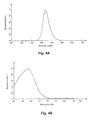
- FIGS. 4A and 4B are drawings representing an example of intensity characteristics of light emitted by a light-emitting part and an example of sensitivity characteristics of a light-receiving part;
- FIG. 5 is a drawing representing an example of light transmission characteristics of the substrate having the light-transmitting film
- FIGS. 6A and 6B are drawings representing parameters relating to designing the reflecting part having the reflecting surface that uses a part of a spherical surface, and to an example of a method for designing the reflecting part;
- FIG. 7 is a drawing representing an example of dimensions of main configurations in the biological information detector
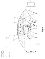
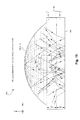
- FIGS. 17A and 17B are drawings used to describe a reflecting surface including a part of a paraboloid (i.e., a paraboloid mirror);
- FIG. 22 is a drawing representing an external appearance of an example of a biological information measuring device (i.e., a wrist pulse rate monitor) including the biological information detector; and
- FIG. 23 is a drawing representing an example of an internal configuration of the biological information measuring device.
- FIGS. 1A and 1B are drawings used to describe an example of a configuration of a biological information detector and a preferable design for a reflecting part.
- FIG. 1A shows a state in which reflected light (i.e., valid light) is incident on a light-receiving region of a light-receiving part.
- FIG. 1B shows a state in which light reflected on a contact-surface side of a contact member forming a protecting part (i.e., directly reflected light; invalid light) is incident on the light-receiving region of the light-receiving part.
- the structure of the biological information detector 200 shown in FIGS. 1A and 1B is identical, and parts that are the same in each drawing are affixed with the same reference numerals.
- the biological information detector 200 can be installed in, e.g., a pulse rate monitor that can be fitted onto a wrist of a person using a wristband or another component (and is not limited to the description given above).
- a pulse rate monitor that can be fitted onto a wrist of a person using a wristband or another component (and is not limited to the description given above).
- the biological information may also be blood oxygen saturation, body temperature, or another variable.
- the biological information detector has a light-emitting part 14 (with an LED or another light-emitting element) for emitting light R1 directed at a detection site 1 (e.g., finger, arm, or wrist) of a test subject 2 (e.g., a human body); a light-receiving part 16 (with a photodiode or another light-receiving element) for receiving light R1' having biological information produced by the light R1 emitted by the light-emitting part 14 being reflected at a blood vessel BV, which is a biological information source at the detection site 1; a reflecting part 18 for reflecting light having biological information; a protecting part 19; and a light-transmitting substrate 11.
- a detection site 1 e.g., finger, arm, or wrist
- a test subject 2 e.g., a human body
- a light-receiving part 16 with a photodiode or another light-receiving element
- the light-receiving part 16 has a light-receiving region (i.e., light-receiving surface) 16-1 on a side towards the reflecting part 18.
- the reflecting part 18 has a reflecting surface (i.e., a reflecting mirror) that is a quadric surface.
- the reflecting surface can be provided on an inner surface of a dome provided on a light path between the light-emitting part 14 and the light-receiving part 16.
- a main body of the reflecting part 18 is made of a resin, and the inner surface (i.e., a quadric surface formed on a side towards the light-receiving part 16) of the main body is subjected to mirror surface finishing (e.g., a metal film or a similar structure is formed on the surface), thereby making it possible to form the reflecting part (i.e., a reflecting optical system).
- mirror surface finishing e.g., a metal film or a similar structure is formed on the surface
- the protecting part 19 has a contact member 19-2 provided with a contact surface SA in contact with (or at least has a possibility of being in contact with) the test subject (i.e., measurement target, e.g., a human body), and a spacer member 19-1.
- the contact member 19-2 and the spacer member 19-1 is formed from a material that is transparent with respect to a wavelength of light R1 emitted by the light-emitting part 14 (e.g., glass).
- the contact member 19-2 is a light-transmitting member.
- the protecting part 19 is also an accommodating part for accommodating the light-emitting part 14 (i.e., an accommodating container or a protective case), and has a function of protecting the light-emitting part 14.
- the substrate 11 is arranged between the reflecting part 18 and the protecting part 19.
- the substrate 11 has two main surfaces.
- a main surface of the substrate 11 on a side towards the light-emitting part 14 may be referred to as a first surface (or a reverse surface)
- a main surface of the substrate 11 on a side towards the reflecting part 18 may be referred to as a second surface (or a front surface).
- the light-emitting part 14 is arranged on the first surface (i.e., the reverse surface) of the substrate 11, and the light-receiving part 16 is arranged on the second surface (i.e., the front surface).
- the light-emitting part 14 and the light-receiving part 16 have an overlap with respect to the plan view.
- the substrate 11 is formed from a material that is transparent with respect to the wavelength of light emitted by the light-emitting part 14 (e.g., polyimide or polyarylate).
- the substrate 11 is a light-transmitting substrate.
- the substrate 11 is arranged between the reflecting part 18 and the protecting part 19, even in an instance in which the light-emitting part 14 and the light-receiving part 16 are arranged on the substrate 11, there is no need to separately provide a mechanism for supporting the substrate 11 itself, and the number of components is smaller. Also, since the substrate 11 is formed from a material that is transparent with respect to the emission wavelength, the substrate 11 can be disposed on a light path from the light-emitting part 14 to the light-receiving part 16. Therefore, there is no need to accommodate the substrate 11 at a position away from the light path, such as in an interior of the reflecting part 18. A biological information detector that can be readily assembled can thus be provided.
- the reflecting part 18 makes it possible to increase the amount of light incident on the light-receiving part 16, thereby increasing the detection accuracy (i.e., signal-to-noise ratio) of the biological information detector.
- the biological information source e.g., the blood vessel BV
- the blood vessel BV which is a biological information source, is located, e.g., within an interior of the detection site 1 (e.g., a finger or an arm (or in a narrower sense, the wrist)) of the test subject 2 (e.g., a human body).
- Light R1 emitted by the light-emitting part 14 (specifically, a main light beam, i.e., an expression meaning light that does not contain reflected light reflected on another member) travels into the interior of the detection site 1 and diffuses or scatters at the epidermis, the dermis, and the subcutaneous tissue.
- the light R1 subsequently reaches the blood vessel BV, which is the biological information source, and is reflected at the blood vessel BV.
- a part of the light R1 is absorbed by the blood vessel BV. Due to an effect of the pulse, the rate of absorption at the blood vessel BV varies, and the amount of reflected light R1' reflected at the blood vessel BV therefore varies. Therefore, biological information (e.g., pulse rate) is thus reflected in the reflected light R1' reflect at the blood vessel BV.
- the reflected light R1' reflected at the blood vessel BV diffuses or scatters at the epidermis, the dermis, and the subcutaneous tissue.
- the reflected light R1' passes through the substrate 11, is reflected on the reflecting part 18, and is directly incident on a light-receiving region (i.e., light-receiving surface) 16-1 of the light-receiving part 16.
- the expression "is directly incident on” is used to express the fact that the light is not routed via, e.g., a complex reflection process, but via, e.g., a smallest possible number of reflections (i.e., via a simple path).
- a biological information detection signal outputted by the light-receiving part 16 includes a pulsating component corresponding to the pulse. Therefore, the pulse rate can be measured according to the detection signal.
- reflected light i.e., invalid light
- a main light beam R2 emitted by the light-emitting part 14 reflects once at a point N1 on the contact member 19-2 on a side towards the contact surface SA (e.g., at a point on the contact surface SA).
- a main light beam R3 emitted by the light-emitting part 14 reflects twice at positions N2 and N3 on the contact member 19-2 on a side towards the contact surface SA (e.g., at points on the contact surface SA).
- a reflected light R3' which has reflected twice (i.e., a twice-reflected light) passes through the substrate 11, reflects again at the reflecting part 18, and is incident on the light-receiving region 16-1 of the light-receiving part 16.
- the reflected light R2' and the reflected light R3' are reflected lights produced by the light emitted by the light-emitting part 14 directly reflecting on the surface (or a vicinity thereof) of the contact member 19-2, which is a light-transmitting member (i.e., directly reflected light).
- the directly reflected light is an invalid light (i.e., noise light) that does not have biological information.
- the S/N i.e., signal-to-noise ratio
- the reflecting part 18 which is a light-collecting optical system, so that directly reflected light (i.e., invalid light) can be inhibited from being incident on the light-receiving region 16-1 of the light-receiving part 16.
- FIG. 2 is a drawing representing a specific example of a configuration of the biological information detector.
- the upper side of FIG. 2 shows an example of a cross-section structure of the biological information detector, and the lower side shows positional relationships between each part with respect to the plan view. Parts in FIG. 2 that are the same as those in FIG. 1 are affixed with the same reference numerals (this also applies to other drawings described further below).
- the aperture diameter of the reflecting part 18 is ⁇ .
- a reflecting surface 18-1 of the reflecting part 18 includes a part of a quadric surface (a spherical surface in this instance; the reflecting surface 18-1 may be, e.g., a substantially hemispherical surface).
- a bottom part of the hemispherical surface is open, not accounting for the substrate or other components.
- the shape of the opening with respect to the plan view i.e., the outer circumferential shape of the reflecting surface with respect to the plan view
- the diameter i.e., the aperture diameter
- the height of the spacer member 19-1 in the protecting part 19 (may be regarded as a spacing between the substrate 11 and a surface of the contact member 19-2 that is opposite the contact surface SA) is ⁇ , and the thickness of the contact member 19-2 is t.
- each of the light-emitting part 14, the light-receiving part 16, and the reflecting part 18 is a circle, each of which circles being concentric with one another (with the center being represented by s).
- the substrate 11 is an optical component as a light-transmitting member, and is also a circuit substrate for forming a circuit.
- the substrate 11 is, e.g., a printed circuit board.
- a wiring 62-1 for the light-receiving part 16 is formed on the first surface (i.e., front surface) of the substrate 11, and wiring 62-2, 62-3 for the light-emitting part 14 are formed on the second surface (i.e., reverse surface) of the substrate 11.
- the wiring 62-1 and the light-receiving part 16 are connected by a bonding wire 63.
- the wiring 62-2 and the light-emitting part 14 are connected by a bonding wire 62.
- the wiring 62-3 and the light-emitting part 14 are connected by a bonding wire 65.
- the first surface (i.e., reverse surface) and the second surface (i.e., front surface) are preferably roughened to a certain extent to prevent printed wiring from detaching.
- a problem is presented in that scattering of light increases. Therefore, in the example shown in FIG. 2 , a light-transmitting film 11-1 and a light-transmitting film 11-2 are respectively formed on the first surface (i.e., reverse surface) and the second surface (i.e., front surface) in a light-transmitting region (or a region excluding a light-blocking region on which wiring or other components are formed) of the substrate 11.
- the light-transmitting films 11-1 and 11-2 are, e.g., a light-transmitting resist film. Forming the light-transmitting films 11-1 and 11-2 in the light-transmitting region of the substrate 11 smoothens the roughness on each of the reverse surface and the front surface and reduces a difference in refraction index between the substrate 11 and air. Light is thereby inhibited from scattering at the front surface and the reverse surface of the substrate 11 (in a broader sense, including the 11-1 and the 11-2). Also, since the difference in the refraction index between the substrate 11 and air is smaller, the degree to which light refracts in the substrate 11 can be reduced. For example, if the substrate 11 is set to a small thickness, light can be considered to travel straight through the substrate 11 without any significant refraction. This contributes towards making it possible to readily simulate the behavior of light, and to readily design an optical system in the biological information detector 200.
- a reflector 20 is provided.
- the reflecting part 18 having the reflecting surface 18-1 including the quadric surface can be referred to as a second reflecting part.
- the reflector 20 has an effect of minimizing a spread of light emitted from the light-emitting part 14, increasing the directivity of light, and reducing the amount of invalid light emitted in a direction other than towards the detection site 1.
- the light-emitting part 14 has a first light-emitting surface 14A and a second light-emitting surface (i.e., a side surface) 14B, and light is also emitted from the second light-emitting surface 14B.
- a protruding part (having, on an inner wall surface of which, a reflecting surface that is an inclined or a curved surface) provided on a periphery of the reflector 20 has an effect of reflecting light emitted from a side surface (i.e., the second light-emitting surface 14B) of the light-emitting part 14 (producing a reflected light R4) and directing the light R4 towards the detection site 1.
- the reflector 20 has a certain amount of width. Therefore, the reflector 20 also has an effect of preventing a part of the directly reflected light (i.e., invalid light) reflected on a vicinity of the contact surface SA of the contact member 19-2 of the protecting part 19 from entering a side towards the reflecting part 18. For example, directly reflected light incident from diagonally below is reflected on an end part and other parts of the reflector 20, and the directly reflected light is thereby prevented from entering the side towards the reflecting part 18.
- the reflector 20 also has an effect of reflecting a part of the directly reflected light towards the detection site 1, thereby converting invalid light into valid light.
- the effect of improving the S/N due to the preferable reflective characteristics of the reflecting optical system that are realized by the invention is thus supplemented with the effect of improving the S/N due to the reflector 20, and the detection accuracy of the information detector 200 is thereby further improved.
- FIG. 3 is a drawing representing, with respect to the plan view, an outer appearance of the substrate coated with the light-transmitting film.
- FIG. 3 shows an outer appearance of the first surface (i.e., the front surface; the surface on the side towards the light-receiving part 16) of the substrate 11 with respect to the plan view.
- the light-transmitting film 11-1 is formed on a light-transmitting region (i.e., a region other than a light-blocking region) on the first surface of the substrate 11.
- the light-transmitting film 11-2 is formed on a light-transmitting region (i.e., a region other than a light-blocking region) is formed on the second surface (i.e., the surface on the side towards the light-emitting part 14).
- a light-transmitting region i.e., a region other than a light-blocking region
- the second surface i.e., the surface on the side towards the light-emitting part 14.
- FIGS. 4A and 4B are drawings representing an example of intensity characteristics of light emitted by the light-emitting part and an example of sensitivity characteristics of the light-receiving part.
- the intensity is at a maximum for light having a wavelength of 520 nm, and the intensity of light having other wavelengths is normalized with respect thereto.
- the wavelengths of light emitted by the light-emitting part 14 are within a range of 470 nm to 600 nm.
- the light-emitting part 14 includes, e.g., an LED.
- the light emitted by the LED has a maximum intensity (or in a broader sense, a peak intensity) within a wavelength range of, e.g., 425 nm to 625 nm, and light emitted by the light-emitting part 14 is, e.g., green in color.
- FIG. 4B shows an example of sensitivity characteristics of the light-receiving part.
- a gallium arsenide phosphide photodiode or a silicon photodiode are examples of the light-receiving part 16 that can be used.
- the gallium arsenide phosphide photodiode has a maximum sensitivity (or in a broader sense, a peak sensitivity) for received light having a wavelength within a range of, e.g., 550 nm to 650 nm.
- the light-receiving part 16 formed by the gallium arsenide phosphide photodiode is more capable of reducing noise components arising from external light than the light-receiving part 16 formed by the silicon photodiode.
- Sensitivity characteristics shown in FIG. 4B are those for an instance in which a gallium arsenide phosphide photodiode is used as the light-receiving part 16.
- the sensitivity is at a maximum for light having a wavelength of 565 nm, and the sensitivity for light having other wavelengths is normalized with respect thereto.
- the wavelength of light received by the light-receiving part 16 at which the sensitivity is at the maximum is within the range of wavelengths emitted by the light-emitting part 14 shown in FIG.
- the sensitivity of infrared light falling within the range of 700 nm to 1100 nm is set at a relative sensitivity of 0.3 (i.e., 30%) or less.
- the wavelength of light received by the light-receiving part 16 at which the wavelength is at the maximum e.g.
- 565 nm is preferably closer to the wavelength at which the intensity of light emitted by the light-emitting part 14 is at the maximum (i.e., 520 nm) than a lower limit of the biological window (i.e., 700 nm).
- FIG. 5 is a drawing representing an example of light transmission characteristics of the substrate coated with the light-transmitting film. Light transmission characteristics shown in FIG. 5 were obtained by calculating the transmittance using intensity of light before passing through the substrate 11 and intensity of light after passing through the substrate 11.
- the transmittance in a region of wavelength equal to or less than 700 nm, which is the lower limit of the biological window, the transmittance is at a maximum for light having a wavelength of 525 nm. Also, in the region of wavelength equal to or less than 700 nm, which is the lower limit of the biological window, the maximum transmittance of light passing through at least one of the light transmission film 11-1 and the light-transmitting film 11-2 falls within a range of ⁇ 10% of the maximum intensity of light with certain wavelength generated by the light-emitting part 14 shown, e.g., in FIG. 4A .
- the light transmission film 11-1 (11-2) it is preferable for the light transmission film 11-1 (11-2) to selectively transmit light emitted by the light-emitting part 14 (e.g., the valid reflected light R1' produced by the light R1 being reflected at the blood vessel BV, shown in FIG. 1A ).
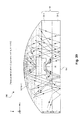
- FIGS. 6A and 6B are drawings representing parameters relating to designing the reflecting part having the reflecting surface that uses a part of a spherical surface, and to an example of a method for designing the reflecting part.
- a mutually perpendicular x-axis, y-axis, and z-axis are shown in order to define a three-dimensional space.
- the z-axis is defined as an optical axis (i.e., a main optical axis).
- a point of intersection between the z-axis and the reflecting surface of the reflecting part 18 is defined as an origin (i.e., a surface origin) m.
- the aperture diameter of the reflecting surface of the reflecting part 18 is represented by ⁇ .
- the reflecting surface of the reflecting part 18 includes a part of a spherical surface, which is a quadric surface.
- the reflecting surface includes a substantially hemispherical surface, which is a part of a spherical surface.
- a focal point of the reflecting part 18 (i.e., a focal point of a light-collecting mirror including the reflecting surface) is f.
- a light beam LG that is parallel to the optical axis i.e., the z-axis
- the light is reflected on the reflecting part 18 and collects at the focal point f.
- the distance between the origin m and the focal point f is the focal distance df.
- a distance that is twice that of the focal distance df is equivalent to the curvature radius r of the reflecting surface. Specifically, the focal distance df is equal to r/2. Also, in FIG. 6A , point p represents a center point of a spherical surface forming the reflecting surface of the reflecting part 18.
- the height of the reflecting surface of the reflecting part 18 is represented by h.
- the height h is established by a distance from the second surface (i.e., the surface on the side towards the reflecting part 18) of the substrate 11 to the origin (i.e., the surface origin) m.
- the height h of the reflecting surface represents the distance between a point m of intersection between the optical axis (i.e., the z-axis) and the reflecting surface (i.e., the surface origin m) and the second surface of the substrate 11 (i.e., the main surface of the substrate 11 that is arranged on a side towards the reflecting surface; the front surface of the substrate 11).
- the height h of the reflecting surface is unambiguously established in correspondence with the curvature radius r and the aperture diameter ⁇ of the reflecting surface.
- ⁇ h is used to represent the difference between the height h of the reflecting surface and the curvature radius r of the reflecting surface.
- the difference ⁇ h (may be referred to simply as ⁇ h) is established by a distance from the second surface of the substrate 11 to the center point p of the spherical surface forming the reflecting surface.
- the height of the spacer member 19-1 in the protecting part 19 i.e., a spacing between the substrate 11 and a surface of the contact member 19-2 that is opposite the contact surface SA
- ⁇ the height of the spacer member 19-1 in the protecting part 19
- t the thickness of the contact member 19-2
- FIG. 6B is a drawing representing how the curvature radius r of the reflecting surface (i.e., the spherical surface forming the reflecting surface) and the shape of the reflecting surface of the reflecting part 18 vary in such an instance.
- ⁇ h i.e., the difference between the height h of the reflecting surface and the curvature radius r of the reflecting surface
- ⁇ h1 i.e., the difference between the height h of the reflecting surface and the curvature radius r of the reflecting surface
- the curvature radius r of the reflecting surface changes from r1 to r2 and r3.
- the curvature radius is r1 at ⁇ h1
- the curvature radius is r2 at ⁇ h2
- the curvature radius is r3 at ⁇ h3.
- the focal distance df of the reflecting part 18 (i.e., a reflecting light-collecting mirror) is half the curvature radius r, when curvature radius r changes, the focal distance df changes in correspondence with the curvature radius r.
- the focal distance is represented by df1
- the focal point f of the reflecting part 18 is represented by f1.
- the focal distance is represented by df2
- the focal point f of the reflecting part 18 is represented by f2.
- the focal distance is represented by df3
- the focal point f of the reflecting part 18 is represented by f3.
- the shape of the reflecting surface including a spherical surface also changes in correspondence with the change in curvature radius r.
- ⁇ is constant, the position of each of points a and b defining the aperture diameter is fixed; therefore, when the curvature radius r changes, the height h of the reflecting surface including a spherical surface also changes in accordance with the change in the curvature radius r.
- the shape of the reflecting surface when the curvature radius r is equal to r1 is represented by 18a.
- the shape of the reflecting surface when the curvature radius r is equal to r2 is represented by 18b.
- the shape of the reflecting surface when the curvature radius r is equal to r3 is represented by 18c.
- the shape of the reflecting surface can also be changed by changing the focal distance df.
- the ⁇ of the reflecting surface is a fixed value (i.e., already known)
- changing, e.g., the focal distance df of the reflecting part 18 i.e., the reflective optical system
- the curvature radius r changes, the difference ⁇ h between the height h and the curvature radius r of the reflecting surface changes.
- the focal distance df of the reflecting surface and the difference ⁇ h between the height h and the curvature radius r of the reflecting surface have a one-to-one correspondence relationship.
- ⁇ h also increases.
- ⁇ h is established.
- the curvature radius r of the contact surface forming the reflecting surface (i.e., the curvature radius of the reflecting surface) can be represented using the following Equation 3 (refer to right-angled triangle indicated by thick arrows in FIG. 6A ).
- Equation 3 Equation 3 (refer to right-angled triangle indicated by thick arrows in FIG. 6A ).
- Mathematical formula 3 r ⁇ ⁇ h 2 + ⁇ / 2 2
- the curvature radius r can be unambiguously established using the above Equation 3, and the spherical surface forming the reflecting surface is established.
- the aperture diameter ⁇ of the reflecting surface i.e., the diameter of the outer circumferential circle of the reflecting surface with respect to the plan view
- the height h of the reflecting surface is unambiguously established.
- a slicing position of the spherical surface i.e., a position at which the spherical surface is sliced along an x-y plane
- the three-dimensional shape and height of the reflecting surface are unambiguously established.
- the above-described method for designing a reflective optical system can be used to design the reflecting part 18 so as to reduce the once-reflected light and the twice-reflected light (which are both invalid directly reflected light) shown in FIG. 1B .
- FIG. 7 is a drawing representing an example of dimensions of main configurations in the biological information detector (the dimensions are not limited to those described in the example below).
- the aperture diameter ⁇ is set to 4.4 mm
- the height ⁇ of the spacer member 19-1 of the protecting part 19 (or, the spacing) is set to 0.53 mm
- the thickness t of the contact member 19-2 is set to 0.4 mm.
- the thickness ta of the light-receiving part 16 is, e.g., 0.28 mm
- the thickness tb of a bottom part of the reflector 20 is, e.g., 0.08 mm
- the thickness tc of the light-emitting part 14 is, e.g., 0.08 mm
- the maximum height td of the reflector 20 is, e.g., 0.2 mm.
- the actual thickness te of the substrate 11 (including the light-transmitting film, i.e., the light-transmitting resist films 11-1 and 11-2) is, e.g., about 0.07 mm. However, since the substrate 11 is sufficiently thin, and, as described above, the light-transmitting resist film maintains smoothness and reduces the difference in refractive index in relation to air, the thickness te of the substrate 11 is ignored in the simulation of the behavior of the reflected light (i.e., te is considered zero). Also, the reflecting surface of the reflecting part 18 includes a part of a spherical surface, which is a quadric surface, as described above.
- the refractive index of glass forming the protecting part 19 is, e.g., 1.52.
- the refractive index of polyamide forming the substrate 11 is, e.g., 1.7.
- Polyarylate (with a refractive index of 1.61) may also be used as a material for the transparent substrate.
- the reflecting surface of the reflecting part 18 is a substantially hemispherical surface.
- the reflecting surface 18-1 of the reflecting part 18 and the spacer member 19-1 are shown, not as a cross-section, but as a shape having spatial depth (this also applies to subsequent drawings).
- trajectories of directly reflected light i.e., invalid light
- the light-emitting part 14 not including light reflected on the reflector or another member
- the contact surface SA i.e., the contact surface SA or a vicinity thereof
- once-reflected light A1 reflects once at a point N1 on the contact member 19-2 on the side towards the contact surface SA.
- the once-reflected light passes through the substrate 11, reflects on the reflecting part 18, and reaches the light-receiving region 16-1 of the light-receiving part 16 in a direct manner (i.e., without undergoing complex reflections or scattering).
- Once-reflected light A2 reflects once at a point N2 on the contact member 19-2 on the side towards the contact surface SA.
- the once-reflected light passes through the substrate 11, reflects on the reflecting part 18, and reaches (i.e., is incident on) the light-receiving region 16-1 of the light-receiving part 16 in a direct manner.
- once-reflected light A3 reflects once at a point N3 on the contact member 19-2 on the side towards the contact surface SA.
- the once-reflected light passes through the substrate 11, reflects on the reflecting part 18, and reaches (i.e., is incident on) the light-receiving region 16-1 of the light-receiving part 16 in a direct manner.
- reflected light R1' reflected at the blood vessel BV i.e., valid reflected light having biological information
- the light-receiving region 16-1 of the light-receiving part 16 i.e., the light-receiving surface
- the ratio of the amount of incident light resulting from the directly reflected light (including once-reflected light and twice-reflected light) being reflected by the reflecting surface and being incident on the light-receiving part 16 (i.e., directly reflected incident light) in relation to the total amount of light received at the light-receiving part 16 to be significantly minimized.
- reflected light R1' reflected at the blood vessel BV i.e., valid reflected light having biological information
- the light-receiving region i.e., the light-receiving surface 16-1 of the light-receiving part 16.
- the twice-reflected light which is the light emitted by the light-emitting part 14 reflecting twice on the side of the contact member 19-2 towards the contact surface SA, being incident on the light-receiving region (i.e., the light-receiving surface) 16-1 of the light-receiving part 16.
- twice-reflected light A4 is reflected twice, at points N4 and N5 on the contact member 19-2 on the side towards the contact surface SA.
- the twice-reflected light passes through the substrate 11, reflects on the reflecting part 18, and reaches (i.e., is incident on) the light-receiving region 16-1 of the light-receiving part 16 in a direct manner.
- twice-reflected light A5 reflects twice at points N6 and N7 on the contact member 19-2 on the side towards the contact surface SA.
- the twice-reflected light passes through the substrate 11, reflects on the reflecting part 18, and reaches (i.e., is incident on) the light-receiving region 16-1 of the light-receiving part 16 in a direct manner.
- twice-reflected light A6 reflects twice at points N8 and N9 on the contact member 19-2 on the side towards the contact surface SA.
- the twice-reflected light passes through the substrate 11, reflects on the reflecting part 18, and reaches (i.e., is incident on) the light-receiving region 16-1 of the light-receiving part 16 in a direct manner.
- reflected light R1' reflected at the blood vessel BV i.e., valid reflected light having biological information
- the light-receiving region i.e., the light-receiving surface 16-1 of the light-receiving part 16.
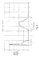
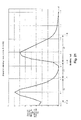
- a focal distance range FA i.e., a range of focal distance df from 1.1 to 1.2
- the focal distance range FA is defined as a first focal distance range.
- the first focal distance range is a focal distance range that corresponds to single reflections.
- a focal distance range FB i.e., a range of focal distance df from 1.2 to 1.41 in which almost no once-reflected light reaches the light-receiving region of the light-receiving part 16.
- the focal distance range FB is defined as a second focal distance range.
- the second focal distance range is a focal distance range within which incidence of directly reflected light on the light-receiving part 16 is minimized.
- a focal distance range FC (i.e., a range of focal distance df from 1.41 to 1.7) in which a ratio, with respect to an amount of light received at the light-receiving region of the light-receiving part 16, of light beams that reflect twice at the contact member 19-2 of the protecting part 19 on a side towards the contact surface SA, then reflects again at the reflecting surface, and arrives at the light-receiving region 16-1 of the light-receiving part 16 in a direct manner, is higher than a predetermined second threshold value (approximately equal to 0%).
- the focal distance range FC is defined as a third focal distance range.
- the third focal distance range is a focal distance range that corresponds to double reflections.
- a behavior of reflected light including, in addition to invalid light, valid light having biological information i.e., valid reflected light; light R1' shown in FIG. 1A .
- the behavior of reflected light including invalid light and valid light is revealed by examining the change in the S/N of a biological information detection signal (e.g., pulse information detection signal) outputted from the light-receiving part 16.
- a biological information detection signal e.g., pulse information detection signal
- a tendency with which the S/N of the detection signal outputted from the light-receiving part 16 changes can be compared with the behavioral tendency of invalid light (i.e., invalid reflected light) shown in FIG. 11 to identify a behavioral tendency of valid light (i.e., valid reflected light) having biological information. For example, if there appears a focal distance range with an increasing S/N in the detection signal within a focal distance range in which the amount of invalid light (i.e., noise N) reaching the light-receiving region 16-1 of the light-receiving part 16 is significantly minimized indicates that the amount of valid light (i.e., signal S) is increasing in the focal distance range.
- the S/N of the detection signal peaks at a vicinity of a focal distance df of 1.28.
- the S/N of the detection signal in each of the first focal distance range FA (i.e., a range of focal distance df from 1.1 to 1.2) and the third focal distance range FC (i.e., a range of focal distance df from 1.41 to 1.7) shown in FIG. 11 is generally lower than the S/N of the detection signal in the second focal distance range FB (i.e., a range of focal distance df from 1.2 to 1.41).
- the second focal distance range FB is a focal distance range in which directly reflected light (i.e., invalid light) is significantly minimized. Therefore, the fact that the S/N of the detection signal in the second focal distance range FB is higher than in other focal distance ranges (i.e., FA and FC) indicates that, specifically, the ratio of valid light (i.e., valid reflected light) in the second focal distance range FB is higher (i.e., more valid light is incident on the light-receiving region 16-1 of the light-receiving part 16) than in the other focal distance ranges (i.e., the first focal distance range FA and the third focal distance range FC).
- the second focal distance range FB i.e., a range of focal distance df from 1.2 to 1.41
- a range of focal distance df from 1.2 to 1.41
- an effect of increasing the amount of valid light (i.e., valid reflected light; light R1' in FIG. 1A ) having pulse rate information as biological information can be obtained. Therefore, setting the focal distance df of the reflecting surface 18-1 of the reflecting part 18 within the focal distance range FB makes it possible to increase the S/N of the detection signal corresponding to detection of the pulse rate as biological information.
- improving the S/N of the detection signal makes it possible to perform detection with a higher degree of accuracy.
- setting the focal distance df of the reflecting surface 18-1 of the reflecting part 18 at a focal distance corresponding to a vicinity of the peak value of the S/N of the detection signal makes it possible to maximize the detection accuracy.
- optical characteristics of the reflecting part were analyzed using the focal distance df as a parameter, a similar result can be obtained in an instance in which ⁇ h is used as a parameter.
- the change in the ratio (%) of the amount of directly reflected light is examined using ⁇ h as a parameter (i.e., a variable).
- ⁇ h range QA corresponding to single reflections (i.e., ⁇ h is within a range of 0.1 to 1.0, in which the ratio is equal to or above 1%; first ⁇ h range); a ⁇ h range QB in which incidence of the directly reflected light on the light-receiving part is minimized (i.e., ⁇ h is within a range of 1.0 to 1.6, in which the ratio is equal to or below 1%; second ⁇ h range); and a ⁇ h range QC corresponding to double reflections ( ⁇ h is within a range of from 1.6 to 2.8, in which the ratio is above 1%; third ⁇ h range).
- the predetermined first and second threshold values are both 1%.
- the S/N of the detection signal outputted from the light-receiving part 16 peaks at a vicinity of a ⁇ h of 1.28.
- the S/N of the detection signal in each of the ⁇ h range QA corresponding to single reflections i.e., a range of ⁇ h from 0.1 to 1.0; the first ⁇ h range
- the ⁇ h range QC corresponding to double reflections i.e., a range of ⁇ h from 1.6 to 2.8; the third ⁇ h range
- the S/N of the detection signal in the second ⁇ h range QB is generally lower than the S/N of the detection signal in the second ⁇ h range QB.
- the second ⁇ h range QB i.e., a range of ⁇ h from 1.0 to 1.6
- the S/N of the pulse rate information detection signal increases (i.e., the S/N of the detection signal improves) relative to other ⁇ h regions (i.e., the first ⁇ h range QA and the third ⁇ h range QC).
- setting ⁇ h within the second ⁇ h range QB makes it possible to improve the S/N of the detection signal corresponding to detection of the pulse rate as biological information. Specifically, the S/N of the detection signal can be improved, thereby making it possible to perform detection with a higher degree of accuracy. In particular, setting ⁇ h at a value corresponding to a vicinity of the peak value of the S/N of the detection signal makes it possible to maximize the detection accuracy.
- FIGS. 15 and 16 represent results obtained when dimension conditions that represent preconditions are partially changed and a similar simulation is performed.
- the aperture diameter ⁇ has been changed from 4.4 mm (as in the example described above) to 3.6 mm.
- a first focal distance range FA' (a range of focal distance df from 0.9 to 0.99)
- a second focal distance range FB' (a range of focal distance df from 0.99 to 1.22)
- a third focal distance range FC' (a range of focal distance df from 1.22 to 1.49) are present.
- the thickness t of the contact member 19-2 has been changed from 0.4 mm (as in the example described above) to 0.3 mm
- the height ⁇ (i.e., the spacing) of the spacer member 19-1 has been changed from 0.53 (as in the example described above) to 0.3 mm.
- a first focal distance range FA" (a range of focal distance df from 1.1 to 1.14), a second focal distance range FB" (a range of focal distance df from 1.14 to 1.28), and a third focal distance range FC" (a range of focal distance df from 1.28 to 1.62) are again present.
- the second focal distance range thus appears between the focal distance range and the third focal distance range. Therefore, it can be seen that a main parameter that has the largest effect on the behavior of directly reflected light of such description is focal distance df (or ⁇ h). Therefore, using the focal distance df (or ⁇ h) as a design parameter is effective when designing the reflecting part 18 to realize preferable reflective characteristics.
- the focal distance df of the reflecting surface of the reflecting part 18 is preferably set within the second focal distance range FB (FB', FB"), which is between the first focal distance range FA (FA', FA”) and the third focal distance range FC (FC', FC").
- the focal distance df of the reflecting surface when the focal distance df of the reflecting surface is established, the curvature radius of the spherical surface forming the reflecting surface is established.
- the spherical surface is therefore unambiguously established.
- the aperture diameter of the reflecting surface since the aperture diameter of the reflecting surface is already known, the position at which the spherical surface is sliced along the x-y plane is unambiguously established, and height h of the reflecting surface including a part of the spherical surface is thereby established.
- the three-dimensional shape and height of the reflecting surface of the reflecting part 18 is thereby unambiguously established.
- the design method described above to adjust the reflective characteristics of the reflecting part 18 makes it possible to minimize incidence of the once-reflected light (i.e., invalid light) and the twice-reflected light (i.e., invalid light) on the light-receiving region 16-1 of the light-receiving part 16 and increase the probability of valid reflected light, having biological information, being incident on the light-receiving region 16-1 of the light-receiving part 16. It is thereby possible to minimize adverse effects (e.g., a decrease in the S/N of the detection signal outputted from the light-receiving part 16) of light reflected on the contact member 19-2 on a side towards the contact surface SA (i.e., directly reflected light).
- adverse effects e.g., a decrease in the S/N of the detection signal outputted from the light-receiving part 16
- the reflecting surface of the reflecting part includes a part of a paraboloid, which is a quadric surface.
- the reflecting surface of the reflecting part was constituted using a spherical surface, which is a quadric surface
- the reflecting surface can also be constituted using a non-spherical surface (i.e., a paraboloid).
- a paraboloid of revolution can be used as the paraboloid.
- the paraboloid of revolution is a quadric surface obtained by revolving a parabola, using a z-axis, which is an axis of symmetry, as an axis of revolution, where an z-axis, among mutually perpendicular x-, y-, and z-axes that define a 3-dimensional space, is an optical axis (i.e., a curved surface represented by a quadratic equation with three unknowns of x, y, and z).
- FIGS. 17A and 17B are drawings used to describe a reflecting surface including a part of a paraboloid (i.e., a paraboloid mirror).
- a paraboloid i.e., a paraboloid mirror
- the paraboloid forming the reflecting surface may be a paraboloid of revolution having the z-axis as an axis of revolution.
- a point of intersection between the z-axis and the paraboloid of revolution is defined as an origin (surface origin) m.
- Equation 5 1 / 2 ⁇ r • x 2 + y 2
- the outer circumferential shape of the reflecting surface 18-1 with respect to the plan view is circular, as with the previous embodiment, and the diameter ⁇ of the circle (i.e., the aperture diameter of the reflecting surface) is set to a predetermined value.
- the focal distance df of the reflecting surface and the curvature radius r of the spherical surface CQ in contact with the origin m of the paraboloid forming the reflecting surface have a one-to-one correspondence relationship. Therefore, when a preferable focal distance df is established, the curvature radius r of the spherical surface in contact with the origin m is established, and the paraboloid of revolution is unambiguously established by the above Equation5.
- the aperture diameter ⁇ of the reflecting surface is already known, a position at which the paraboloid of revolution is sliced along an x-y plane is thereby established, and the height h of the reflecting surface is unambiguously established.
- the three-dimensional shape (and height) of the reflecting surface is thereby unambiguously established.
- the reflecting surface 18-1 of the reflecting part 18 shown in FIG. 18 includes a part of a paraboloid, In FIG. 18 , the reflecting surface of the reflecting part 18 is shown, not as a cross-section, but as a shape having spatial depth (this also applies to subsequent drawings).
- trajectories of directly reflected light i.e., invalid light
- the light-emitting part 14 not including light reflected on the reflector or another member
- the contact surface SA i.e., the contact surface SA or a vicinity thereof
- reflected light from the blood vessel i.e., valid reflected light having biological information
- the light-receiving region i.e., the light-receiving surface 16-1 of the light-receiving part 16.
- the twice-reflected light which is the light emitted by the light-emitting part 14 reflecting twice on the side of the contact member 19-2 towards the contact surface SA, being incident on the light-receiving region (i.e., the light-receiving surface) 16-1 of the light-receiving part 16.
- the light-receiving region i.e., the light-receiving surface
- a first focal distance range FA i.e., a range of focal distance df from 0.55 mm to 1.0 mm
- a second focal distance range FB i.e., a range of focal distance df from 1.0 mm to 1.15 mm
- the ratio of the amount of directly reflected light incident on the light-receiving part is minimized so as to be equal to or below 1% (the first and second threshold values, used as predetermined threshold values in the present example to determine whether the amount of reflected light is high or low, are 1%). Also, the ratio of directly reflected light is almost zero in a vicinity of the focal distance df of 1.1.
- a third focal distance range FC i.e., a range of focal distance df from 1.15 mm to 1.55 mm.
- the focal distance of the reflecting surface (i.e., the paraboloid mirror) of the reflecting part 18 is preferably set within the second focal distance range FB, which is between the first focal distance range FA and the third focal distance range FC.
- the decrease in S/N of the detection signal outputted from the light-receiving part 16, caused by the directly reflected light (i.e., invalid light), is thereby minimized.
- the detection accuracy increases.
- the focal distance is most preferably set in the vicinity of 1.1.
- setting the focal distance df within the second focal distance range makes it possible to increase the S/N of the detection signal corresponding to detection of the pulse rate as biological information. Specifically, improving the S/N of the detection signal makes it possible to perform detection with a higher degree of accuracy.
- setting the focal distance df to a value corresponding to a vicinity of the peak value of the S/N of the detection signal i.e., 1.1
- the focal distance df of the reflecting surface when the focal distance df of the reflecting surface is established, the three-dimensional shape and height of the reflecting surface are unambiguously established. Therefore, using the design method described above makes it possible to obtain a reflecting part 18 having preferable reflective characteristics with which the effect of directly reflected light can be reduced.
- FIG. 22 is a drawing representing an external appearance of an example of a biological information measuring device (i.e., a wrist pulse rate monitor) including the biological information detector.
- the biological information measuring device 300 may further include a wristband 150 capable of attaching the biological information detector 200 to an arm (or specifically, a wrist), which is the detection site 1, of the test subject (i.e., human body) 2.
- the biological information is the pulse rate, and the pulse rate (i.e., "72"), which is a measurement result, is displayed on a display part 165 provided to the biological information measuring device 300.
- the biological information measuring device 300 also functions as a wristwatch.
- the time (e.g., "8:45 am") is displayed on the display part 165 provided to the biological information measuring device 300.
- an opening part is provided to a back cover of the biological information measuring device 300 that also functions as the wristwatch, and the protecting part (i.e., protective case) 19 described above is exposed in the opening part.
- FIG. 23 is a drawing representing an example of an internal configuration of the biological information measuring device.
- the biological information measuring device 300 includes the biological information detector 200 shown in FIG. 1 and other drawings, and a biological information measuring part 202 for measuring biological information from a light reception signal generated by the light-receiving part 16 of the biological information detector. In FIG. 23 , a portion that functions as a clock is omitted.
- the biological information detector 200 may have the light-emitting part 14, the light-receiving part 16, and a control circuit 161 for controlling the light-emitting part 14.
- the biological information detector 200 may further have an amplification circuit 162 for amplifying the light reception signal from the light-receiving part 16.
- the biological information detector 200 may further have an acceleration detecting part 166.
- the biological information measuring part 202 may have an A/D conversion circuit 163 for performing A/D conversion of the light reception signal from the light-receiving part 16, and a pulse rate computation circuit 164 for computationally obtaining the pulse rate.
- the biological information measuring device 300 may further have the display part 165 for displaying the pulse rate.
- the biological information detector 200 may have the acceleration detecting part 166; in such an instance, the biological information measuring part 202 may have an A/D conversion circuit 167 for performing A/D conversion on a detection signal from the acceleration detecting part 166, and a digital signal processing circuit 168 for processing a digital signal.
- the configuration of the biological information measuring device shown in FIG. 23 is given by way of example, but is not limited to the configuration shown.
- the pulse rate computation circuit 164 maybe, e.g., an MPU (i.e., a microprocessing unit) of an electronic device installed with the biological information detector 200.
- the control circuit 161 drives the light-emitting part 14.
- the control circuit 161 is, e.g., a constant current circuit, delivers a predetermined voltage (e.g. 6 V) to the light-emitting part 14 via a protective resistance, and maintains a current flowing to the light-emitting part 14 at a predetermined value (e.g. 2 mA).
- the control circuit 161 is capable of driving the light-emitting part 14 in an intermittent manner (e.g. at 128 Hz) in order to reduce consumption current.
- the control circuit 161 is formed on, e.g., a motherboard (not shown), and wiring between the control circuit 161 and the light-emitting part 14 is formed, e.g., on the substrate 11.
- the amplification circuit 162 shown in FIG. 23 is capable of removing a DC component from the light reception signal (i.e., an electrical current) generated in the light-receiving part 16, extracting only an AC component, amplifying the AC component, and generating an AC signal.
- the amplification circuit 162 removes the DC component at or below a predetermined wavelength using, e.g., a high-pass filter, and buffers the AC component using, e.g., an operational amplifier.
- the light reception signal contains a pulsating component and a body movement component.
- the amplification circuit 162 and the control circuit 161 are capable of feeding a power supply voltage, for operating the light-receiving part 16 at, e.g., reverse bias, to the light-receiving part 16.
- the power supply to the light-receiving part 16 is also intermittently fed, and the AC component is also intermittently amplified.
- the amplification circuit 162 is formed on, e.g., the mother board (not shown), and wiring between the amplification circuit 162 and the light-receiving part 16 is formed on, e.g., the substrate 11.
- the amplification circuit 162 may also have an amplifier for amplifying the light reception signal at a stage prior to the high-pass filter.
- the amplifier can be formed, e.g., on an end part of the substrate 11.
- the A/D conversion circuit 163 converts an AC signal generated in the amplification circuit 162 into a digital signal (i.e., a first digital signal).
- the acceleration detecting part 166 detects, e.g., gravitational acceleration in three axes (i.e., x-axis, y-axis, and z-axis) and generates an acceleration signal. Movement of the body (i.e., the arm), and therefore the movement of the biological information measuring device, is reflected in the acceleration signal.
- the A/D conversion circuit 167 converts the acceleration signal generated in the acceleration detecting part 166 into a digital signal (i.e., a second digital signal).
- the digital signal processing circuit 168 uses the second digital signal to remove or reduce the body movement component in the first digital signal.
- the digital signal processing circuit 168 may be formed by, e.g., an FIR filter or another adaptive filter.
- the digital signal processing circuit 168 inputs the first digital signal and the second digital signal into the adaptive filter and generates a filter output signal in which noise has been removed or reduced.
- the pulse rate computation circuit 164 uses, e.g., fast Fourier transform (or in a broader sense, scrambling Fourier transform) to perform a frequency analysis on the filter output signal.
- the pulse rate computation circuit 164 identifies a frequency that represents a pulsating component based on a result of the frequency analysis, and computationally obtains a pulse rate.
- Using the wrist pulse rate monitor shown in FIG. 22 makes it possible to obtain, e.g., a time-series pulse rate information while the user performs jogging or another exercise.
- the obtained pulse rate information can be used in a versatile manner such as for improving the constitution of the user.
- situations such as the position of the wrist pulse rate monitor becoming displaced as a result of the exercise performed by the user, or the wrist pulse rate monitor being affected by external light, can be expected, and the number of factors that can reduce the detection accuracy (i.e., the measurement accuracy) is increased.
- a biological information detector i.e., an in-vivo probe installed in the pulse oximeter can be obtained using a configuration that is identical to that in the previous embodiments (e.g., the configuration shown in FIGS. 1A and 2 ).
- the biological information detector 200 in the pulse oximeter includes the light-emitting part 14 and the light-receiving part 16.
- the light-emitting part 14 emits, e.g., a red light and infrared light. Reflected light, produced by the light emitted by the light-emitting part 14 reflecting at the detection site 1 (e.g., fingertip, arm, or wrist), is measured using the light-receiving part 16. Red-light and infrared absorbance of haemoglobin in the blood differ depending on presence of a bond with oxygen. Therefore, the arterial oxygen saturation (S p O 2 ) can be measured by measuring the reflected light at the light-receiving part 16 and analyzing the reflected light.
- S p O 2 the arterial oxygen saturation
- Components that have been reflected by an artery or the like and components that have been reflected by a vein or soft tissue, which are included in all reflected light, can be distinguished from each other using the fact that pulsating components originate from arterial blood. It is also possible to count the pulse rate at the same time from pulsating pulse components.
- the configuration of the biological information measuring part 202 for use in a pulse rate monitor shown in FIG. 23 can be used as a configuration of the biological information measuring part for use in the pulse oximeter.
- the pulse rate computation circuit 164 shown in FIG. 23 is replaced by an arterial oxygen saturation analysis circuit 164 in which a pulse rate computation circuit and an FFT or another approach is used.
Applications Claiming Priority (1)
| Application Number | Priority Date | Filing Date | Title |
|---|---|---|---|
| JP2010022836A JP5672709B2 (ja) | 2010-02-04 | 2010-02-04 | 生体情報検出器、生体情報測定装置および生体情報検出器における反射部の設計方法 |
Publications (1)
| Publication Number | Publication Date |
|---|---|
| EP2360464A1 true EP2360464A1 (fr) | 2011-08-24 |
Family
ID=44021782
Family Applications (1)
| Application Number | Title | Priority Date | Filing Date |
|---|---|---|---|
| EP20110153023 Withdrawn EP2360464A1 (fr) | 2010-02-04 | 2011-02-02 | Détecteur d'informations biologiques, dispositif de mesure d'informations biologiques et procédé pour la conception d'une partie réfléchissante dans le détecteur d'informations biologiques |
Country Status (4)
| Country | Link |
|---|---|
| US (4) | US8823944B2 (fr) |
| EP (1) | EP2360464A1 (fr) |
| JP (1) | JP5672709B2 (fr) |
| CN (1) | CN102144919B (fr) |
Families Citing this family (28)
| Publication number | Priority date | Publication date | Assignee | Title |
|---|---|---|---|---|
| JP5672709B2 (ja) * | 2010-02-04 | 2015-02-18 | セイコーエプソン株式会社 | 生体情報検出器、生体情報測定装置および生体情報検出器における反射部の設計方法 |
| JP5682200B2 (ja) * | 2010-09-28 | 2015-03-11 | セイコーエプソン株式会社 | 生体情報検出器及び生体情報測定装置 |
| JP5998516B2 (ja) * | 2012-02-23 | 2016-09-28 | セイコーエプソン株式会社 | 拍動検出装置、電子機器及びプログラム |
| FR2995686B1 (fr) * | 2012-09-20 | 2016-12-23 | Commissariat Energie Atomique | Detecteur optique d'un gaz |
| KR101450815B1 (ko) | 2013-01-29 | 2014-10-14 | 인덕대학교 산학협력단 | 생체 신호 측정 장치 |
| US20140264055A1 (en) * | 2013-03-15 | 2014-09-18 | Advantage Controls, Llc | System and process for detecting phosphonate |
| US9891099B2 (en) * | 2013-07-30 | 2018-02-13 | Elbit Systems Of America, Llc | Optical detector and system therefor |
| JP5929952B2 (ja) * | 2014-03-27 | 2016-06-08 | セイコーエプソン株式会社 | 生体情報検出装置及び電子機器 |
| CN104367309B (zh) * | 2014-11-03 | 2016-09-14 | 深圳市莱通光学科技有限公司 | 一种反射式腕式心率计及反射式腕式心率测量方法 |
| CN104382578A (zh) * | 2014-11-21 | 2015-03-04 | 广西智通节能环保科技有限公司 | 一种心率监测系统 |
| CN104473627A (zh) * | 2014-11-21 | 2015-04-01 | 广西智通节能环保科技有限公司 | 一种智能脉搏监测腕表 |
| JP2016123714A (ja) * | 2015-01-05 | 2016-07-11 | セイコーエプソン株式会社 | 生体情報測定モジュール、および生体情報測定機器 |
| US10448897B2 (en) * | 2015-02-25 | 2019-10-22 | Polar Electro Oy | Heart activity measurement |
| DE102015104312A1 (de) * | 2015-03-23 | 2016-09-29 | Osram Opto Semiconductors Gmbh | Sensor zur Erfassung einer biometrischen Funktion |
| CN105030217A (zh) * | 2015-06-09 | 2015-11-11 | 吉林大学 | 一种便携式运动监测检测设备及运动监测检测方法 |
| EP3111842A1 (fr) * | 2015-06-30 | 2017-01-04 | Nokia Technologies Oy | Appareil comprenant un détecteur de lumière, une source lumineuse et une optique |
| US10244987B2 (en) * | 2015-08-13 | 2019-04-02 | Pixart Imaging Inc. | Physiological detection system with adjustable signal source and operating method thereof |
| CN106510655A (zh) * | 2016-12-12 | 2017-03-22 | 东莞市广信知识产权服务有限公司 | 一种脉搏测量手环 |
| EP3342337B1 (fr) | 2016-12-29 | 2020-11-04 | Nokia Technologies Oy | Agencement de capteurs pour un capteur de mesure physiologique |
| US11389105B2 (en) * | 2017-10-31 | 2022-07-19 | Brittany Molkenthin | Systems and methods for measuring a quantity of breast milk consumed by a baby |
| US11331014B2 (en) | 2018-03-14 | 2022-05-17 | Welch Allyn, Inc. | Compact, energy efficient physiological parameter sensor system |
| KR20210021041A (ko) * | 2018-07-17 | 2021-02-24 | 알프스 알파인 가부시키가이샤 | 검출 장치, 프로그램 및 검출 시스템 |
| JP7155704B2 (ja) * | 2018-07-20 | 2022-10-19 | セイコーエプソン株式会社 | 生体センサーモジュール及び生体情報測定装置 |
| EP3613344B1 (fr) * | 2018-08-23 | 2021-08-04 | Nokia Technologies Oy | Appareil photodétecteur de mesure de fréquence cardiaque |
| CN110115568B (zh) * | 2019-03-19 | 2021-12-21 | 浙江大学山东工业技术研究院 | 一种基于智能手机的心率血氧仪 |
| JP2021131334A (ja) * | 2020-02-20 | 2021-09-09 | 株式会社リコー | 測定装置、及び生体情報測定装置 |
| WO2021247386A1 (fr) * | 2020-06-01 | 2021-12-09 | Rce Technologies, Inc. | Dispositifs spectroscopiques infrarouges et méthodes d'utilisation pour l'évaluation transdermique d'un patient |
| CN113640254B (zh) * | 2021-08-11 | 2023-10-24 | 淮阴师范学院 | 一种可保持自平衡的作物生长信息传感器 |
Citations (5)
| Publication number | Priority date | Publication date | Assignee | Title |
|---|---|---|---|---|
| US4078858A (en) * | 1975-12-30 | 1978-03-14 | Gretag Aktiengesellschaft | Measuring head |
| EP0095759A1 (fr) * | 1982-05-28 | 1983-12-07 | Központi Elelmiszeripari Kutato Intezet | Système de détection pour mesurer l'intensité d'une radiation, dispersée dans un angle prédéterminé par un spécimen irradié sous un angle d'incidence déterminé |
| JP2004337605A (ja) | 2003-04-23 | 2004-12-02 | Otax Co Ltd | 光プローブ、これを用いた計測システム、および、これを用いた反射光検出方法 |
| WO2005010568A2 (fr) * | 2003-07-21 | 2005-02-03 | The Titan Corporation | Ecran de controle optique de signes de vie |
| US20080097221A1 (en) * | 2004-02-17 | 2008-04-24 | Joseph Florian | Optical in-vivo monitoring systems |
Family Cites Families (17)
| Publication number | Priority date | Publication date | Assignee | Title |
|---|---|---|---|---|
| GB8811919D0 (en) | 1988-05-20 | 1988-06-22 | Amersham Int Plc | Biological sensors |
| JP2000116611A (ja) * | 1998-10-16 | 2000-04-25 | Kowa Spinning Co Ltd | 脈拍センサ |
| JP2004121539A (ja) | 2002-10-02 | 2004-04-22 | Seiko Epson Corp | 体動検出装置 |
| JP2004333179A (ja) * | 2003-04-30 | 2004-11-25 | Inax Corp | 反射型光センサ |
| WO2004110273A1 (fr) * | 2003-06-13 | 2004-12-23 | Matsushita Electric Industrial Co., Ltd. | Dispositif de mesure de graisse par voie optique |
| JP2005181157A (ja) | 2003-12-19 | 2005-07-07 | Inax Corp | 反射型光センサ |
| KR100622243B1 (ko) * | 2004-02-17 | 2006-09-14 | 오므론 가부시키가이샤 | 광학식 측정 장치 및 광학식 측정 방법 |
| JP2007010556A (ja) * | 2005-07-01 | 2007-01-18 | Sharp Corp | 光学式測距センサ及びこれを備えた機器 |
| JP2007279020A (ja) * | 2006-03-13 | 2007-10-25 | Citizen Holdings Co Ltd | 装着型電子機器および装着型電子機器を用いた生体測定装置 |
| WO2007105771A1 (fr) * | 2006-03-15 | 2007-09-20 | Omron Corporation | Puce destinee a un capteur de resonance de plasmons de surface et capteur de resonance de plasmons de surface |
| EP1882916A1 (fr) * | 2006-07-20 | 2008-01-30 | Interuniversitair Microelektronica Centrum | Spectromètre catadioptrique compact |
| EP1908401A1 (fr) * | 2006-10-06 | 2008-04-09 | ETA SA Manufacture Horlogère Suisse | Méthode et dispositif de mesure d'une pulsation cardiaque lors de la pratique d'un sport rythmique |
| JP2008126017A (ja) * | 2006-11-27 | 2008-06-05 | Otax Co Ltd | 光センサ及びこれを用いた計測システム |
| JP5093597B2 (ja) * | 2007-03-30 | 2012-12-12 | 日本光電工業株式会社 | 生体信号測定用プローブ |
| JP5454147B2 (ja) | 2010-01-05 | 2014-03-26 | セイコーエプソン株式会社 | 生体情報検出器及び生体情報測定装置 |
| JP5446915B2 (ja) * | 2010-01-21 | 2014-03-19 | セイコーエプソン株式会社 | 生体情報検出器及び生体情報測定装置 |
| JP5672709B2 (ja) * | 2010-02-04 | 2015-02-18 | セイコーエプソン株式会社 | 生体情報検出器、生体情報測定装置および生体情報検出器における反射部の設計方法 |
-
2010
- 2010-02-04 JP JP2010022836A patent/JP5672709B2/ja not_active Expired - Fee Related
-
2011
- 2011-01-27 US US13/015,210 patent/US8823944B2/en not_active Expired - Fee Related
- 2011-02-01 CN CN201110034171.2A patent/CN102144919B/zh not_active Expired - Fee Related
- 2011-02-02 EP EP20110153023 patent/EP2360464A1/fr not_active Withdrawn
-
2014
- 2014-06-13 US US14/304,106 patent/US9179848B2/en not_active Expired - Fee Related
- 2014-10-22 US US14/520,896 patent/US9241644B2/en not_active Expired - Fee Related
-
2015
- 2015-12-11 US US14/966,824 patent/US9913582B2/en not_active Expired - Fee Related
Patent Citations (5)
| Publication number | Priority date | Publication date | Assignee | Title |
|---|---|---|---|---|
| US4078858A (en) * | 1975-12-30 | 1978-03-14 | Gretag Aktiengesellschaft | Measuring head |
| EP0095759A1 (fr) * | 1982-05-28 | 1983-12-07 | Központi Elelmiszeripari Kutato Intezet | Système de détection pour mesurer l'intensité d'une radiation, dispersée dans un angle prédéterminé par un spécimen irradié sous un angle d'incidence déterminé |
| JP2004337605A (ja) | 2003-04-23 | 2004-12-02 | Otax Co Ltd | 光プローブ、これを用いた計測システム、および、これを用いた反射光検出方法 |
| WO2005010568A2 (fr) * | 2003-07-21 | 2005-02-03 | The Titan Corporation | Ecran de controle optique de signes de vie |
| US20080097221A1 (en) * | 2004-02-17 | 2008-04-24 | Joseph Florian | Optical in-vivo monitoring systems |
Also Published As
| Publication number | Publication date |
|---|---|
| US20150045639A1 (en) | 2015-02-12 |
| US9179848B2 (en) | 2015-11-10 |
| US9241644B2 (en) | 2016-01-26 |
| US8823944B2 (en) | 2014-09-02 |
| JP5672709B2 (ja) | 2015-02-18 |
| CN102144919B (zh) | 2015-04-22 |
| US20140296671A1 (en) | 2014-10-02 |
| JP2011156313A (ja) | 2011-08-18 |
| CN102144919A (zh) | 2011-08-10 |
| US9913582B2 (en) | 2018-03-13 |
| US20110190605A1 (en) | 2011-08-04 |
| US20160095519A1 (en) | 2016-04-07 |
Similar Documents
| Publication | Publication Date | Title |
|---|---|---|
| US9241644B2 (en) | Biological information detector, biological information measuring device, and method for designing reflecting part in biological information detector | |
| US8814802B2 (en) | Biological information detector and biological information measuring device | |
| JP5454147B2 (ja) | 生体情報検出器及び生体情報測定装置 | |
| US11857301B1 (en) | Non-invasive flow monitoring | |
| CN109152544B (zh) | 使用粘附激光散斑对比分析的血流量测量系统 | |
| JP5581697B2 (ja) | 生体情報検出器及び生体情報測定装置 | |
| US20080097221A1 (en) | Optical in-vivo monitoring systems | |
| US9814399B2 (en) | Biological information detection apparatus | |
| JP5742104B2 (ja) | 光デバイス及び生体情報検出器 | |
| US11259712B2 (en) | Wearable reflectance-mode PPG sensor network having improved detected signal strength | |
| JP2008099890A (ja) | 生体情報測定装置 | |
| JP5625426B2 (ja) | センサー装置及び生体情報測定装置 | |
| JP5604897B2 (ja) | 光デバイスの製造方法、光デバイス及び生体情報検出器 | |
| TWI551269B (zh) | 攜帶型分析裝置以及系統 | |
| EP2353502A2 (fr) | Détecteur d'informations biologiques et dispositif de mesure d'informations biologiques | |
| CN210871602U (zh) | 血氧检测装置 | |
| JP2017189415A (ja) | 生体情報測定装置 | |
| WO2020122164A1 (fr) | Appareil de mesure de signaux biologiques | |
| CN115191934A (zh) | 具有测量脉搏波功能的电子终端设备 |
Legal Events
| Date | Code | Title | Description |
|---|---|---|---|
| PUAI | Public reference made under article 153(3) epc to a published international application that has entered the european phase |
Free format text: ORIGINAL CODE: 0009012 |
|
| AK | Designated contracting states |
Kind code of ref document: A1 Designated state(s): AL AT BE BG CH CY CZ DE DK EE ES FI FR GB GR HR HU IE IS IT LI LT LU LV MC MK MT NL NO PL PT RO RS SE SI SK SM TR |
|
| AX | Request for extension of the european patent |
Extension state: BA ME |
|
| 17P | Request for examination filed |
Effective date: 20120123 |
|
| 17Q | First examination report despatched |
Effective date: 20170816 |
|
| STAA | Information on the status of an ep patent application or granted ep patent |
Free format text: STATUS: THE APPLICATION HAS BEEN WITHDRAWN |
|
| 18W | Application withdrawn |
Effective date: 20171006 |