EP2360331A1 - Bewegliche Bodenstütze - Google Patents
Bewegliche Bodenstütze Download PDFInfo
- Publication number
- EP2360331A1 EP2360331A1 EP10153735A EP10153735A EP2360331A1 EP 2360331 A1 EP2360331 A1 EP 2360331A1 EP 10153735 A EP10153735 A EP 10153735A EP 10153735 A EP10153735 A EP 10153735A EP 2360331 A1 EP2360331 A1 EP 2360331A1
- Authority
- EP
- European Patent Office
- Prior art keywords
- ground
- support
- bore
- movable
- movable ground
- Prior art date
- Legal status (The legal status is an assumption and is not a legal conclusion. Google has not performed a legal analysis and makes no representation as to the accuracy of the status listed.)
- Withdrawn
Links
Images


Classifications
-
- E—FIXED CONSTRUCTIONS
- E04—BUILDING
- E04H—BUILDINGS OR LIKE STRUCTURES FOR PARTICULAR PURPOSES; SWIMMING OR SPLASH BATHS OR POOLS; MASTS; FENCING; TENTS OR CANOPIES, IN GENERAL
- E04H12/00—Towers; Masts or poles; Chimney stacks; Water-towers; Methods of erecting such structures
- E04H12/22—Sockets or holders for poles or posts
- E04H12/2238—Sockets or holders for poles or posts to be placed on the ground
-
- E—FIXED CONSTRUCTIONS
- E04—BUILDING
- E04H—BUILDINGS OR LIKE STRUCTURES FOR PARTICULAR PURPOSES; SWIMMING OR SPLASH BATHS OR POOLS; MASTS; FENCING; TENTS OR CANOPIES, IN GENERAL
- E04H12/00—Towers; Masts or poles; Chimney stacks; Water-towers; Methods of erecting such structures
- E04H12/22—Sockets or holders for poles or posts
- E04H12/2207—Sockets or holders for poles or posts not used
- E04H12/2215—Sockets or holders for poles or posts not used driven into the ground
- E04H12/223—Sockets or holders for poles or posts not used driven into the ground with movable anchoring elements; with separately driven anchor rods
Definitions
- the present invention generally relates to ground supports that are easily movable. More specifically, the present invention relates to ground supports for supporting upwardly extending objects, such as parasols. In particular, the present invention relates to ground supports for a quick securing and release from the ground.
- a movable ground support for being secured to the ground by a number of securing rods, each securing rod having a ground-engaging portion for being inserted into the ground and a support-engaging portion for engaging the movable ground support
- the movable ground support comprising a solid body having a bottom surface, a top surface, and a number of side surfaces interconnecting the bottom and top surfaces, the bottom surface being adapted to be placed in facial contact with and on top of a flat ground surface, the number of side surfaces defining a lower circumferential edge or edge portion at the transition to the bottom surface and an upper circumferential edge or edge portion at the transition to the top surface, a support recess in the top surface for providing support for an upwardly extending object under a load being parallel to said flat ground surface, and a plurality of bores
- skew is to be understood as no bore being parallel or perpendicular with respect to another bore or to the extension direction of the support recess into the solid body.
- Non-converging and non-diverging in the present context is to be understood as no bore is extending along a line that crosses a similar line of another bore or of the support recess.
- securing rods of any length that are inserted in any order or simultaneously.
- the fact that the body is solid allows for it to be heavy even though it is compact.
- the movable ground support can provide some small temporary support without first anchoring it to the ground by securing rods.
- the securing rods are elongated, e.g. smooth-sided spikes, flanged screws, or helical screws, and secure the movable ground support by engaging both the solid body and the ground.
- the bottom surface of the body may be flat. This, in combination with the lower and upper circumferential edges or edge portions, allows according to the first aspect of the present invention for a number of the compact movable ground supports to be stacked on top and/or beside each other.
- Examples of upwardly extending objects are a support pole of a parasol, a flag pole, a pole supporting a windscreen, a badminton net-post, and a beach-volleyball net-post.
- the specified positioning of the inlet and outlet apertures of the plurality of bores allows for a compact solid body of the movable ground support.
- Each bore of the plurality of bores may define an angle to the flat ground surface in the range of approximately 45 to approximately 75 degrees, in the range of approximately 55 to approximately 65 degrees, or of approximately 60 degrees. These specified angles are favourable for securing the movable ground support to the ground, in particular to a lawn if screw-threaded securing rods are employed.
- the support recess may go through the solid body from the top surface to the bottom surface. This allows for a tight fitting between the support surface and an object, e.g. the upwardly extending object or an insert for providing support for an upwardly extending object. However, a tight fitting may result in the object getting stuck in the support recess, in particular if the object is subjected to significant horizontal loads. The object may then be loosened by tapping on it from the direction of the bottom side.
- the support recess may have a circular, triangular, or square cross section. Further, the support recess may be frustoconical and each bore of the plurality of bores may define a cylinder.
- a through-going support recess is particularly advantageous if the support recess is frustoconical, as with this particular geometric shape the tendency to get stuck in the support recess is much larger than if the support recess is cylindrical.
- All bores of the plurality of bores may have the same length. Further, all bores of the plurality of bores may define approximately the same angle to the flat ground surface. Further, the plurality of bores may define a rotational symmetry with respect to the support recess. This allows for a symmetric insertion of securing rods into the ground, making the secured movable ground support stable against loads from different and varying directions.
- Each bore of the plurality of bores may have a widening portion at its outlet aperture for receiving material from the ground. This has the effect that the bottom surface may remain in facial contact with the flat ground surface, even though material from the ground is released backwards when inserting the securing rods into the ground. This has the advantage that the movable ground support will stand on a stable footing upon the ground after anchoring.
- the top surface may define a plurality of flat surface portions.
- Each bore of the plurality of bores may extend perpendicularly to and have its inlet aperture located on a flat surface portion of the plurality of flat surface portions. This allows for a nondestructive and releasable engagement between the securing rods and the movable ground support, in particular if the securing rods have flanges for cooperating facially with the flat surface portions.
- the support recess may be intersected by a first geometric plane perpendicular to the flat ground surface and dividing the solid body in a first and a second part.
- the plurality of bores may comprise a first bore having its inlet aperture on the first part and its outlet aperture on, or at least partly on, the second part, and a second bore having its inlet aperture on the second part and its outlet aperture on, or at least partly on, the first part.
- the support recess may be intersected by a second geometric plane perpendicular to the flat ground surface and perpendicular to the first geometric vertical plane and dividing the solid body in a third and a fourth part.
- the first bore may have its inlet aperture and its outlet aperture on the third part, and the second bore may have its inlet aperture and its outlet aperture on the fourth part This allows for the movable ground support to provide a support against loads in a direction perpendicular to the second geometric plane.
- the plurality of bores may comprise a third bore having its inlet aperture on the third part and its outlet aperture on, or at least partly on, the fourth part. This allows for the movable ground support to provide a support particularly favourable against loads in a direction perpendicular to the second geometric plane.
- the plurality of bores may comprise a fourth bore having its inlet aperture on the fourth part and its outlet aperture on, or at least partly on, the third part. This also allows for the movable ground support to provide support particularly favourable against loads in a direction perpendicular to the second geometric plane.
- the third bore may have its inlet aperture and its outlet aperture on the second part, and the fourth bore may have its inlet aperture and its outlet aperture on the first part. This allows for the movable ground support to provide a support against loads in a direction perpendicular to the first geometric plane.
- a movable ground support system comprising a movable ground support according to the first aspect of the present invention and a number of securing rods, each securing rod of the number of securing rods having a ground-engaging portion for being inserted into the ground and a support-engaging portion for engaging the movable ground support.
- the second aspect of the present invention may have all the features and advantages of the first aspect of the present invention.
- each securing rod of the number of securing rods may have an external screw-thread for inserting it into the ground by rotation. This allows for a stable securing of the movable ground support, even in loose soil or in sand. It also allows for the plurality of bores to have a narrow angle with respect to the flat ground surface. Further, it allows for the use of electrical screwdrivers, or the like, to be used for inserting the securing rods into the ground, which requires less effort than when hammering spikes into the ground.
- each securing rod of the number of securing rods may have a circular cross-section and no external screw-thread.
- the support-engaging portion of each securing rod of the number of securing rods may have a flange for engaging a flat surface portion of the plurality of flat surface portions. This allows for the prevention of the securing rods to damage the solid body of the movable ground support, in particular if the ground-engaging portions of the securing rods have external screw-threads by which the movable ground support is tightened to the ground.
- the flange of the securing rod in combination with a ground-engaging portion with an external screw-thread or a helical screw shape, allows for the solid body to be tightened to the ground, which in turn allows a finely adjustable alignment of the movable ground support, e.g. to put the upwardly extending object in a vertical orientation, by tightening or loosening the securing rods,
- the movable ground support system according to the second aspect of the present invention may further comprise an insert for being received in and supported by the support recess of the movable ground support, the insert having an insert recess for providing support for an upwardly extending object under a load being parallel to the flat ground surface. This allows for the movable ground support to be adapted for use with different upwardly extending objects.
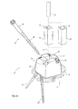
- Fig. 1 depicts a parasol 10, where the screen 12 and the central pole 14 are held in an upright position by a movable ground support system 18.
- the movable ground support system 18 is secured to the ground 16 by four securing rods 24.
- the movable ground support 20 of the system 18 comprises a solid body 22 at which centre the central pole 14 of the parasol 10 is supported and held in an upright position.
- the system 18 comprises the movable ground support 20 and the four securing rods 24.
- the movable ground support 20 supports the parasol 10 against horizontal loads acting upon it.
- the movable ground support 20 only provides a support against vertical loads that are directed downward
- the movable ground support 20 is fitted with a fastener or catch that engages and secures the central pole 14 of the parasol 10, thereby providing a support against vertical loads that are directed upward.
- the parasol is only given as an example of an upwardly extending object that can be supported by the movable ground support system 18. Examples of other upwardly extending objects are flag poles, poles supporting windscreens, badminton net-posts, and beach-volleyball net-posts.
- Fig. 2A shows an exploded view of the movable ground support system 18.
- the anchoring of the solid body 22 of the movable ground support 20 to the ground 16 is here shown in greater detail than in the previous Fig. 1 .
- the securing rods 24 go through the body 22 via four bores 26.
- the rods have a ground-engaging portion 38 and a support-engaging portion 40.
- the ground-engaging portion 38 goes through the solid body 22 and into the ground 16 when securing the movable ground support 20 to the ground 16.
- most of the support-engaging portion 40 is positioned within the bore 26, only the flange 60 and the head 58 are outside of the bore.
- the securing rods 24 enter the bore 26 along an insertion direction 41 defined by the bores 26.
- the bores 26 have a circular cross-section with the same diameter throughout their lengths.
- the movable ground support 20 has a support recess 28 going through the solid body 22.
- the movable ground support system 18 further has an insert 30 adapted to be received by and cooperate with the support recess 28 along the extension direction 31 of the support recess 28.
- the extension direction 31 in the presently preferred embodiment is vertical if the movable ground support 20 is placed on a horizontal, flat ground surface 16.
- the insert 30 has an insert recess 32 for receiving the central pole 14 of the parasol shown in Fig. 1 ,
- the insert 30 can be replaced by another insert 34 having a different insert recess 36 for receiving a central pole of a larger diameter.
- the support recess 28 and the inserts 30 and 34 are frustoconical with a square cross-section.
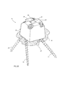
- Fig. 2B depicts the fully assembled movable ground support system 18.
- the movable ground support 20 is secured to the ground 16 by four securing rods 24.
- the bores through the solid body 22 are skew, non-converging and non-diverging with respect to one another and the extension direction 31 of the insert recess 36. This means that the securing rods 24 will not intersect each other or a central pole 14 supported by the support recess 28, neither above nor below ground, when anchoring.
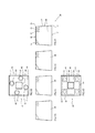
- Figs. 3A, 3C, 3E, and 3F are side views of the movable ground support of the preferred embodiment of the invention.
- the bottom surface 44 is planar and on the opposite side of the solid body 22 from the top surface 46.
- the bottom surface 44 and the top surface 46 are interconnected by four side surfaces 48.
- the transition between the side surfaces 48 and the bottom surface 44 defines a lower circumferential edge 50.
- the transition between the side surfaces 48 and the top surface 46 defines an upper circumferential edge 52.
- the top surface 46 defines four flat surface portions 54, where each of the four bores 26 extends perpendicularly from one of the flat surface portions 54 downward and has its inlet aperture located on the flat surface portion 54.
- Fig. 3B is a bottom view of the movable ground support according to the preferred embodiment of the present invention.
- the bottom surface 44 defines a square shape, which means that the lower circumferential edge 50 traces a closed polygon having four segments of equal lengths and at right angles with respect to one another.
- the support recess 28 goes through the solid body 22 of the movable ground support 20.
- each of the four bores 26 has a widening portion 42 at the bottom surface 44. The widening portions 42 can receive material from the ground that is released when the movable ground support 20 is anchored by securing rods 24 as shown in the previous Figs. 2A and 2B .
- Fig. 3D shows the movable ground support 20 from the top side.
- the transition between the top surface 46 and the side surfaces 48 defines the upper circumferential edge 52.
- the upper circumferential edge 52 lies within the lower circumferential edge 50 due to the inclined side surfaces 48.
- Each of the bores 26 has its inlet aperture located on the flat surface portion 54 of the top surface 46 of the movable ground support 20.
- Fig. 3G is a perspective view of the movable ground support 20.
- Each of the four side surfaces 48 is inclined so that the solid body 22 is narrowing from the lower circumferential edge 50 to the upper circumferential edge 52. Due to the four flat surface portions 54 of the top surface 46 and the four side surfaces 48, the upper circumferential edge 52 defines a polygon having sixteen segments.
- the top surface 46 has horizontal surface portions between each pair of neighbouring flat surface portions 54.
- the movable ground support 20 in Fig. 3G has no insert in the support recess 28, as in the previous Fig. 2B . Further, there are no securing rods in the bores 26.
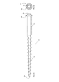
- Fig. 4A shows a securing rod 24 from its side.
- the securing rod has a ground-engaging portion 38 with an external screw-thread for engaging the ground.
- At one side of the ground-engaging portion 38 is a sharp tip 56, while on the other side there is a support-engaging portion 40 without any external screw-thread for engaging the movable ground support shown in the previous figures.
- the support-engaging portion 40 ends in a head 58, at which a flange 60 extends outwards.
- the support-engaging portion 40 has a circular cross-section with a diameter slightly smaller than the diameters of the circular bores 26 shown in the previous figures.
- the flange 60 has a diameter that is larger than the diameter of the bores 26, whereby it facially engages the flat surface portions of the previously described movable grounds support 20.
- the head 58 is hexagonal in shape, by which it can be engaged by a hollow key or socket wrench. In Fig. 4B the securing rod 24 is shown from the direction of its head 58.
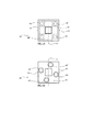
- FIG 5A a top view of the movable ground support 20 of the preferred embodiment of the present invention is shown.
- a first geometric plane 70 perpendicular to a flat ground surface upon which the bottom surface 44 of the solid body 22 rests, divides the solid body 22 in a first and a second part.
- the first part is below the dashed line 70 representing the first geometric plane, while the second part is located above the dashed line 70.
- a second geometric plane 72 perpendicular to a flat ground surface upon which the bottom surface 44 of the solid body 22 rests and to the first geometric plane 70, divides the solid body in a third and a fourth part.
- the third part is to the right of the dashed line 72 representing the second geometric plane, while the fourth part is located to the left of the dashed line 72.
- FIG 5B a top view of the movable ground support 20 of the preferred embodiment of the present invention is shown. This particular view is obtained by a 180 degree rotation the solid body 22 in Figure 5A around the dashed line 70.
- the first part of the solid body 22 is located above the dashed line 70 in Figure 5B
- the second part is located below the dashed line 70.
- the third and fourth parts are still on the right and left sides, respectively, of the dashed line 72.
- a first bore has its inlet aperture 74' positioned on the first part and its outlet aperture 74" positioned on the second part. Both the inlet aperture 74' and the outlet aperture 74" of the first bore are positioned on the third part, i.e. to the right of the dashed line 72.
- a second bore has its inlet aperture 76' positioned on the second part and its outlet aperture 76" positioned on the first part. Both the inlet aperture 76' and the outlet aperture 76" of the second bore are positioned on the third part, i.e. to the left of the dashed line 72.
- a third bore has its inlet aperture 78' positioned on the third part and its outlet aperture 78" positioned on the fourth part. Both the inlet aperture 78' and the outlet aperture 78" of the third bore are positioned on the second part.
- a fourth bore has its inlet aperture 80' positioned on the fourth part and its outlet aperture 80" positioned on the third part. Both the inlet aperture 80' and the outlet aperture 80" of the fourth bore are positioned on the first part. All of the inlet apertures 74'-80' are located on the top surface 46, while all of the outlet apertures 74"-80" are located on the bottom surface 44.
- the solid body 22 of the movable ground support 20 is manufactured of pine wood
- the insert 34 of the movable ground support system 18 is also manufactured of pine wood
- the plurality of securing rods 24 is manufactured from a solid piece of aluminium.
- Each of the four segments of the lower circumferential edge 50, or the width of the solid body 22 at the bottom surface 44, is 0.21 m in length.
- the width of the solid body 22 at the top surface 46 is 0.19 m.
- the length of the through-going support recess 28, or the height of the solid body 22, is 0.18 m.
- the square cross-section of the support recess 28 has a side of 0.080 m at the top surface 46 and of 0.075 m at the bottom surface 44.
- the diameters of the bores 26 is 0.035 m, while the widening portions have are elliptical shape, due to the sloping bores 26, with the smallest width of 0.050 m and the largest width of 0.060 m at the bottom surface 44.
- the lower side of each bore has a length of 0.19 m and defines an angle to the bottom surface 44 of 60 degrees.
- the flat surface portions are rectangular with sides of lengths of 0.055 m and 0.065 m.
- the insert recess 36 has a circular cross-section with a diameter of 0.060 m.
- the insert recess 36 has the same height as the support recess, i.e. 0.18 m.
Priority Applications (3)
| Application Number | Priority Date | Filing Date | Title |
|---|---|---|---|
| EP10153735A EP2360331A1 (de) | 2010-02-16 | 2010-02-16 | Bewegliche Bodenstütze |
| PCT/EP2011/052291 WO2011101372A2 (en) | 2010-02-16 | 2011-02-16 | Movable ground support |
| EP11706201A EP2536901A2 (de) | 2010-02-16 | 2011-02-16 | Bewegliche bodenstütze |
Applications Claiming Priority (1)
| Application Number | Priority Date | Filing Date | Title |
|---|---|---|---|
| EP10153735A EP2360331A1 (de) | 2010-02-16 | 2010-02-16 | Bewegliche Bodenstütze |
Publications (1)
| Publication Number | Publication Date |
|---|---|
| EP2360331A1 true EP2360331A1 (de) | 2011-08-24 |
Family
ID=41727865
Family Applications (2)
| Application Number | Title | Priority Date | Filing Date |
|---|---|---|---|
| EP10153735A Withdrawn EP2360331A1 (de) | 2010-02-16 | 2010-02-16 | Bewegliche Bodenstütze |
| EP11706201A Withdrawn EP2536901A2 (de) | 2010-02-16 | 2011-02-16 | Bewegliche bodenstütze |
Family Applications After (1)
| Application Number | Title | Priority Date | Filing Date |
|---|---|---|---|
| EP11706201A Withdrawn EP2536901A2 (de) | 2010-02-16 | 2011-02-16 | Bewegliche bodenstütze |
Country Status (2)
| Country | Link |
|---|---|
| EP (2) | EP2360331A1 (de) |
| WO (1) | WO2011101372A2 (de) |
Cited By (9)
| Publication number | Priority date | Publication date | Assignee | Title |
|---|---|---|---|---|
| GB2493199A (en) * | 2011-07-28 | 2013-01-30 | C S Scaffold Contracts Ltd | Anchor for bracing of fencing |
| US20140174003A1 (en) * | 2011-06-28 | 2014-06-26 | Neil Despotellis | Footing plates |
| AT14437U1 (de) * | 2014-02-18 | 2015-11-15 | Hilber Franz | Verankerungsvorrichtung und Tragvorrichtung |
| USD901282S1 (en) | 2019-09-25 | 2020-11-10 | Dale Clayton Miller | Plate assembly |
| JP2021002934A (ja) * | 2019-06-21 | 2021-01-07 | 匡伯 河邉 | ソーラーパネル用の架台支柱の固定具、及び、その使用方法 |
| CZ308813B6 (cs) * | 2020-05-18 | 2021-06-02 | KALONEROS s.r.o. | Patka pro uchycení nosného sloupku, zejména dopravních značek |
| USD953843S1 (en) | 2019-09-25 | 2022-06-07 | Dale Clayton Miller | Pile system |
| US11788246B2 (en) | 2020-12-14 | 2023-10-17 | Dale Clayton Miller | Micropile connection for supporting a vertical pile |
| US11828038B2 (en) | 2020-07-10 | 2023-11-28 | Dale Clayton Miller | Pile connection for horizontally fixing an elongated beam for a foundation support system |
Citations (9)
| Publication number | Priority date | Publication date | Assignee | Title |
|---|---|---|---|---|
| US1808633A (en) | 1928-12-17 | 1931-06-02 | Carver Edmund Clifton | Ground anchor and like anchoring device |
| US5039256A (en) | 1990-03-15 | 1991-08-13 | Richard Gagliano | Pinned foundation system |
| US5243795A (en) | 1991-09-20 | 1993-09-14 | Bruce Roberts | Tie down stake |
| US5395184A (en) | 1993-01-29 | 1995-03-07 | Gagliano; Richard J. | Structure load transfer systems |
| US5873679A (en) | 1996-11-12 | 1999-02-23 | Cusimano; Matt | Seismic foundation pier with ground anchor means |
| US6735911B1 (en) | 2003-02-28 | 2004-05-18 | Billy W. Alexander | Earth anchor |
| US20050025577A1 (en) * | 2003-07-31 | 2005-02-03 | Gagliano Richard J. | Novel surface structures and methods thereof |
| AT8142U2 (de) * | 2005-08-03 | 2006-02-15 | Oberhofer Stahlbau Ges M B H | Alpinanker |
| DE102008031110A1 (de) * | 2008-07-01 | 2010-01-07 | Alpintechnik Ag | Stabilisator mit Justiervorrichtung für Bodenverankerungen |
Family Cites Families (6)
| Publication number | Priority date | Publication date | Assignee | Title |
|---|---|---|---|---|
| DE823336C (de) * | 1950-07-14 | 1952-11-17 | Wilhelm Francois | Bodenanker fuer waagerechte und lotrechte Zugbeanspruchung |
| US4452018A (en) * | 1980-07-01 | 1984-06-05 | Hill Claud A | Device for anchoring a building |
| FR2794487B1 (fr) * | 1999-06-02 | 2001-08-10 | Ravoyard Holding | Socle destine a la fixation au sol d'un abri |
| DE102004053518B4 (de) * | 2004-10-29 | 2012-10-04 | Recover Systems Gmbh | Mobilzaunfuß |
| US20070187564A1 (en) * | 2006-02-03 | 2007-08-16 | Mcguire Stephen J | Load bearing and load anchoring, ground to structure foundation pier |
| US8672287B2 (en) * | 2007-05-29 | 2014-03-18 | Oliver Joen-An Ma | Adjustable rotation base |
-
2010
- 2010-02-16 EP EP10153735A patent/EP2360331A1/de not_active Withdrawn
-
2011
- 2011-02-16 EP EP11706201A patent/EP2536901A2/de not_active Withdrawn
- 2011-02-16 WO PCT/EP2011/052291 patent/WO2011101372A2/en active Application Filing
Patent Citations (9)
| Publication number | Priority date | Publication date | Assignee | Title |
|---|---|---|---|---|
| US1808633A (en) | 1928-12-17 | 1931-06-02 | Carver Edmund Clifton | Ground anchor and like anchoring device |
| US5039256A (en) | 1990-03-15 | 1991-08-13 | Richard Gagliano | Pinned foundation system |
| US5243795A (en) | 1991-09-20 | 1993-09-14 | Bruce Roberts | Tie down stake |
| US5395184A (en) | 1993-01-29 | 1995-03-07 | Gagliano; Richard J. | Structure load transfer systems |
| US5873679A (en) | 1996-11-12 | 1999-02-23 | Cusimano; Matt | Seismic foundation pier with ground anchor means |
| US6735911B1 (en) | 2003-02-28 | 2004-05-18 | Billy W. Alexander | Earth anchor |
| US20050025577A1 (en) * | 2003-07-31 | 2005-02-03 | Gagliano Richard J. | Novel surface structures and methods thereof |
| AT8142U2 (de) * | 2005-08-03 | 2006-02-15 | Oberhofer Stahlbau Ges M B H | Alpinanker |
| DE102008031110A1 (de) * | 2008-07-01 | 2010-01-07 | Alpintechnik Ag | Stabilisator mit Justiervorrichtung für Bodenverankerungen |
Cited By (11)
| Publication number | Priority date | Publication date | Assignee | Title |
|---|---|---|---|---|
| US20140174003A1 (en) * | 2011-06-28 | 2014-06-26 | Neil Despotellis | Footing plates |
| US9850638B2 (en) * | 2011-06-28 | 2017-12-26 | Neil Despotellis | Footing plates |
| US20180106010A1 (en) * | 2011-06-28 | 2018-04-19 | Neil Despotellis | Footing plates |
| GB2493199A (en) * | 2011-07-28 | 2013-01-30 | C S Scaffold Contracts Ltd | Anchor for bracing of fencing |
| AT14437U1 (de) * | 2014-02-18 | 2015-11-15 | Hilber Franz | Verankerungsvorrichtung und Tragvorrichtung |
| JP2021002934A (ja) * | 2019-06-21 | 2021-01-07 | 匡伯 河邉 | ソーラーパネル用の架台支柱の固定具、及び、その使用方法 |
| USD901282S1 (en) | 2019-09-25 | 2020-11-10 | Dale Clayton Miller | Plate assembly |
| USD953843S1 (en) | 2019-09-25 | 2022-06-07 | Dale Clayton Miller | Pile system |
| CZ308813B6 (cs) * | 2020-05-18 | 2021-06-02 | KALONEROS s.r.o. | Patka pro uchycení nosného sloupku, zejména dopravních značek |
| US11828038B2 (en) | 2020-07-10 | 2023-11-28 | Dale Clayton Miller | Pile connection for horizontally fixing an elongated beam for a foundation support system |
| US11788246B2 (en) | 2020-12-14 | 2023-10-17 | Dale Clayton Miller | Micropile connection for supporting a vertical pile |
Also Published As
| Publication number | Publication date |
|---|---|
| WO2011101372A2 (en) | 2011-08-25 |
| EP2536901A2 (de) | 2012-12-26 |
| WO2011101372A3 (en) | 2012-03-22 |
Similar Documents
| Publication | Publication Date | Title |
|---|---|---|
| EP2360331A1 (de) | Bewegliche Bodenstütze | |
| US7438273B2 (en) | Anchor for securing an object to ground | |
| US7089694B2 (en) | Sign post assembly and method for the same | |
| US7731131B2 (en) | Roof block | |
| US9850638B2 (en) | Footing plates | |
| US9145706B2 (en) | Post anchor apparatus | |
| US8875451B1 (en) | Stackable foundation anchors | |
| CN107427114B (zh) | 用于为杆状元件构建支撑基座的成套部件 | |
| US20060051183A1 (en) | Ground anchors | |
| US10364543B2 (en) | Method and apparatus for portable stake mounting | |
| US8082934B1 (en) | Umbrella anchoring device | |
| US20110036026A1 (en) | Ergonomic post with integral anchor | |
| US9657493B2 (en) | Post reinforcement | |
| US10089906B2 (en) | Apparatus for interior signpost support | |
| US20040065802A1 (en) | Ground anchoring sunshade umbrella stand | |
| US6938871B1 (en) | Flag or umbrella support pole | |
| US10351404B1 (en) | Tent stake removal tool | |
| US10260252B2 (en) | Barbed stake | |
| US6401408B1 (en) | Molded plastic stake with multiple shoulders | |
| CA2437299A1 (en) | Ground anchor | |
| US10487979B2 (en) | T-post hanger plate | |
| US10407936B2 (en) | Adjustable sign post base for real estate sign | |
| US20180216306A1 (en) | Anchor Device and Method | |
| US6131884A (en) | Tool for extraction of stakes | |
| US20140017423A1 (en) | Apparatus, system and/or a method for holding a pole |
Legal Events
| Date | Code | Title | Description |
|---|---|---|---|
| PUAI | Public reference made under article 153(3) epc to a published international application that has entered the european phase |
Free format text: ORIGINAL CODE: 0009012 |
|
| PUAI | Public reference made under article 153(3) epc to a published international application that has entered the european phase |
Free format text: ORIGINAL CODE: 0009012 |
|
| AK | Designated contracting states |
Kind code of ref document: A1 Designated state(s): AT BE BG CH CY CZ DE DK EE ES FI FR GB GR HR HU IE IS IT LI LT LU LV MC MK MT NL NO PL PT RO SE SI SK SM TR |
|
| STAA | Information on the status of an ep patent application or granted ep patent |
Free format text: STATUS: THE APPLICATION IS DEEMED TO BE WITHDRAWN |
|
| 18D | Application deemed to be withdrawn |
Effective date: 20120225 |