EP2360055B1 - Ramp device for vehicle - Google Patents
Ramp device for vehicle Download PDFInfo
- Publication number
- EP2360055B1 EP2360055B1 EP08878919.3A EP08878919A EP2360055B1 EP 2360055 B1 EP2360055 B1 EP 2360055B1 EP 08878919 A EP08878919 A EP 08878919A EP 2360055 B1 EP2360055 B1 EP 2360055B1
- Authority
- EP
- European Patent Office
- Prior art keywords
- slope
- slope section
- vehicular
- section
- extended
- Prior art date
- Legal status (The legal status is an assumption and is not a legal conclusion. Google has not performed a legal analysis and makes no representation as to the accuracy of the status listed.)
- Not-in-force
Links
- 230000005484 gravity Effects 0.000 claims description 25
- 229910000838 Al alloy Inorganic materials 0.000 description 3
- 230000000694 effects Effects 0.000 description 2
- 239000000463 material Substances 0.000 description 2
- 230000004888 barrier function Effects 0.000 description 1
- 238000000034 method Methods 0.000 description 1
- 239000011347 resin Substances 0.000 description 1
- 229920005989 resin Polymers 0.000 description 1
- 238000003466 welding Methods 0.000 description 1
Images

Classifications
-
- A—HUMAN NECESSITIES
- A61—MEDICAL OR VETERINARY SCIENCE; HYGIENE
- A61G—TRANSPORT, PERSONAL CONVEYANCES, OR ACCOMMODATION SPECIALLY ADAPTED FOR PATIENTS OR DISABLED PERSONS; OPERATING TABLES OR CHAIRS; CHAIRS FOR DENTISTRY; FUNERAL DEVICES
- A61G3/00—Ambulance aspects of vehicles; Vehicles with special provisions for transporting patients or disabled persons, or their personal conveyances, e.g. for facilitating access of, or for loading, wheelchairs
- A61G3/02—Loading or unloading personal conveyances; Facilitating access of patients or disabled persons to, or exit from, vehicles
- A61G3/06—Transfer using ramps, lifts or the like
- A61G3/061—Transfer using ramps, lifts or the like using ramps
-
- B—PERFORMING OPERATIONS; TRANSPORTING
- B60—VEHICLES IN GENERAL
- B60P—VEHICLES ADAPTED FOR LOAD TRANSPORTATION OR TO TRANSPORT, TO CARRY, OR TO COMPRISE SPECIAL LOADS OR OBJECTS
- B60P1/00—Vehicles predominantly for transporting loads and modified to facilitate loading, consolidating the load, or unloading
- B60P1/43—Vehicles predominantly for transporting loads and modified to facilitate loading, consolidating the load, or unloading using a loading ramp mounted on the vehicle
-
- B—PERFORMING OPERATIONS; TRANSPORTING
- B60—VEHICLES IN GENERAL
- B60P—VEHICLES ADAPTED FOR LOAD TRANSPORTATION OR TO TRANSPORT, TO CARRY, OR TO COMPRISE SPECIAL LOADS OR OBJECTS
- B60P1/00—Vehicles predominantly for transporting loads and modified to facilitate loading, consolidating the load, or unloading
- B60P1/43—Vehicles predominantly for transporting loads and modified to facilitate loading, consolidating the load, or unloading using a loading ramp mounted on the vehicle
- B60P1/435—Vehicles predominantly for transporting loads and modified to facilitate loading, consolidating the load, or unloading using a loading ramp mounted on the vehicle the ramp being attached to or making part of the side- or tailboards of the vehicle
-
- Y—GENERAL TAGGING OF NEW TECHNOLOGICAL DEVELOPMENTS; GENERAL TAGGING OF CROSS-SECTIONAL TECHNOLOGIES SPANNING OVER SEVERAL SECTIONS OF THE IPC; TECHNICAL SUBJECTS COVERED BY FORMER USPC CROSS-REFERENCE ART COLLECTIONS [XRACs] AND DIGESTS
- Y10—TECHNICAL SUBJECTS COVERED BY FORMER USPC
- Y10S—TECHNICAL SUBJECTS COVERED BY FORMER USPC CROSS-REFERENCE ART COLLECTIONS [XRACs] AND DIGESTS
- Y10S414/00—Material or article handling
- Y10S414/134—Handicapped person handling
Definitions
- the present invention relates to a vehicular slope apparatus according to the preamble of claim 1.
- the invention is particularly effective for preventing a situation in which the slope apparatus is used in an insufficiently extended state.
- a vehicular slope apparatus may include a plurality of slope sections that can be folded (folding slope apparatus) or slidingly moved (sliding slope apparatus) so that the slope apparatus can be housed inside the vehicle when the slope apparatus is not used.
- the folding slope apparatus has an almost constant slope angle since the folding slope apparatus has a constant total length in an extended state.
- the end of the slope apparatus may not come in contact with the ground, or the slope may be bent upward or downward to some extent.
- the sliding slope apparatus can be used (i.e., a wheelchair can be loaded and unloaded) in a normal state in which the slope section is extended to a maximum extent (see FIG. 6A ), and can also be used in a state in which the slope section is received within another slope section, and comes in contact with the ground (see FIG. 6B ). In the latter case, however, it may be difficult to handle the wheelchair due to the steepness of the slope.
- the slope angle ⁇ (b) is larger than the slope angle ⁇ (a) in a normally extended state, it may be difficult to load and unload the wheelchair.
- the inventor of the invention conducted extensive studies in order to prevent loading of a wheelchair when a sliding slope apparatus is not sufficiently extended.
- a sliding slope apparatus is normally configured so that the base end of a first slope is rotatably connected to a vehicle, and a second slope section (and third slope section) is slidingly extended. Therefore, the inventor focused on the fact that the center of gravity of the slope section moves away from the vehicle when the second slope is extended.
- JP-A-2006-137320 discloses a torsion bar that produces a biasing force in the housing direction in order to prevent rapid rotation when extending the slope apparatus and reduce the operation force required to house the slope apparatus in the vehicle.
- JP-A-2006-137320 merely assists rotation in the housing direction so that the front slope plate and the rear slope plate are housed to overlap.
- JP-A-2004-224086 discloses technology that provides the tailgate with an assistance mechanism that assists a closing force applied to the tailgate and the slope member when folding and housing the slope member inside the vehicle.
- JP-A-2004-224086 merely prevents rapid rotation of the tailgate, and reduces the manual operation force required when closing the tailgate. Specifically, the technology disclosed in JP-A-2004-224086 does not prevent a situation in which the slide slope is insufficiently extended.
- a vehicular slope apparatus of the related art is known from DE 1 925 442 U .
- This document discloses a sloping ramp arranged at a vehicle which can be folded down.
- the energy generated by folding down the sloping ramp is stored in one or several portion springs by which the stored energy can be used again to fold up the sloping ramp.
- US 5,273,335 A discloses a combination ramp which has also the function of a tail gate for use with pickup trucks and the like.
- the ramp can be nested into a compact barrier to function as a tail gate and can also be unfolded and extended to function as a ramp from a ground.
- An object of the invention is to provide a safe sliding vehicular slope apparatus that makes it possible to easily detect an insufficiently extended state, and prevent a situation in which the slope apparatus is used in a steeply sloping state.
- a vehicular slope apparatus including a first slope section that is rotatably connected to a body of a vehicle at its base end, and a second slope section that is slidably connected to an extension side of the first slope section, the first slope section including an assistance section that applies an assistance force (Mf) in a direction in which the first slope section rotates upwardly and toward the body around the base end as a rotation center, the assistance force (Mf) being larger than a downward moment that occurs at a center of gravity (M1) of the entire of the vehicular slope apparatus when the entire of the vehicular slope apparatus is horizontalized in a state in which the second slope section is received within the first slope section, and is smaller than a downward moment that occurs at a center of gravity (M2) of the entire of the vehicular slope apparatus when the second slope section is extended from the first slope section to a maximum extent, the center of gravity of the entire slope section continuously changing from the center of gravity M1 to the center of gravity M2 when the second slope section is slidingly extended
- the expression "the second slope section is slidably connected to the extension side of the first slope section” means that the vehicular slope apparatus is configured so that the second slope section is slidingly extended from the first slope section in the direction in which the vehicular slope apparatus is extended from the vehicle.
- the invention also includes a slope apparatus in which the second slope section is divided into a plurality of slope sections, and each slope section is slidingly extended.
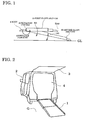
- the assistance force (Mf) is larger than the downward moment that occurs at the center of gravity M1 when the entire of the vehicular slope apparatus is horizontalized in a state in which the second slope section is received within the first slope section, the end of the vehicular slope apparatus does not come in contact with the ground GL when the vehicular slope apparatus is rotated away from the vehicle in a state in which the second slope section is not extended (see FIG. 1 (schematic view)).
- the center of gravity of the vehicular slope apparatus moves away from the vehicle when the second slope section is extended from this state.
- the assistance force is smaller than the downward moment that occurs at the center of gravity M2 when the second slope section is extended from the first slope section to a maximum extent (see FIG. 1 ), the end of the vehicular slope apparatus comes in contact with the ground.
- the invention utilizes the effect whereby the center of gravity of the entire of the vehicular slope apparatus moves away from the vehicle upon extension of the second slope section, the center of gravity of the entire of the vehicular slope apparatus continuously changes from the center of gravity M 1 to the center of gravity M2 when the second slope section is slidingly extended from the first slope section.
- the second slope section is preferably extended from the first slope section within a range of 350 to 1500 mm. In this case, it is preferable that the distance between the rotation center and the center of gravity M 1 when the second slope section is received within the first slope section differ from the distance between the rotation center and the center of gravity M2 when the second slope section is extended to a maximum extent by 100 mm or more.
- the assistance means may be arbitrarily selected insofar as the above effects are obtained.
- the assistance means may be a coil spring, a torsion spring, a combination of a damper structure and a tensile structure, or the like.
- the assistance means is integrally provided on the vehicular slope apparatus, the degree of freedom of the design of the vehicle on which the vehicular slope apparatus is mounted increases.
- the end of the vehicular slope apparatus does not come in contact with the ground due to the assistance force in the direction in which the vehicular slope apparatus rotates upwardly and toward the interior of the vehicle. Therefore, a situation in which the second slope section is insufficiently extended can be easily observed with the naked eye, and a situation in which the vehicular slope apparatus is used in a steeply sloping state can be prevented.
- the vehicular slope apparatus has a rear gate connection type structure (i.e., the rear gate (tailgate) of the vehicle is also extended when the vehicular slope apparatus is extended), it is possible to prevent a situation in which design parts such as a bumper cover provided on the rear gate come in contact with the ground or the like (i.e., are damaged) due to the steepness of the slope.
- a rear gate connection type structure i.e., the rear gate (tailgate) of the vehicle is also extended when the vehicular slope apparatus is extended
- FIG. 2 is a perspective view illustrating a vehicle equipped with a vehicular slope apparatus.
- FIG. 2 illustrates a state in which a vehicular slope apparatus 1 is extended.
- a rear door 3 of a body 2 of the vehicle is opened, and a wheelchair (not shown) is loaded into an interior 4 of the vehicle.
- the vehicular slope apparatus 1 is used to load and unload the wheelchair (not shown) into and from the rear floor inside the interior 4.
- the vehicular slope apparatus 1 is housed upright on the rear side of the interior 4 when the vehicular slope apparatus 1 is not used (see FIG. 3 ), and is extended during use so that the end of the vehicular slope apparatus 1 comes in contact with the ground, and the entire of the vehicular slope apparatus 1 slopes gently (see FIG. 2 ).
- FIG. 4 is a view illustrating a vehicular slope apparatus according to one embodiment of the invention.
- FIG. 4 illustrates a state in which a vehicular slope apparatus 1 is extended.
- the vehicular slope apparatus 1 includes a first slope section 10 that is positioned on the side of the body 2, and a second slope section 20 that is positioned on the side of the ground G, the first slope section 10 and the second slope section 20 are adjacent to each other when the vehicular slope apparatus 1 is extended.
- the first slope section 10 includes a first rail member 11 that is provided on each end of the first slope section 10 in the widthwise direction and extends in the slide direction (i.e., the extension direction of the vehicular slope apparatus 1), a ground-side floor member 12, a plurality of intermediate floor members 13, and a vehicle-side floor member 14, the floor members 12, 13, and 14 extending in the widthwise direction of the first slope section 10.
- the second slope section 20 includes a second rail member 21 that is provided on each end of the second slope section 20 in the widthwise direction and extends in the slide direction, a ground-side floor member 22, a plurality of intermediate floor members 23, and a vehicle-side floor member 24, the floor members 22, 23, and 24 extending in the widthwise direction of the second slope section 20.
- the two second rail members 21 of the second slope section 20 are positioned inside the two first rail members 11 of the first slope section 10.
- Each end of the floor members 12, 13, and 14 of the first slope section 10 and the floor members 22, 23, and 24 of the second slope section 20 in the widthwise direction is fitted into a groove that is formed (extends) in each of the first rail member 11 and the second rail member 21 in the longitudinal direction, and is secured by welding or using a screw.
- a wheelchair or the like can be moved over the surface of the floor members (12 to 14 and 22 to 24).
- the first rail member 11 and the second rail member 21 prevent a situation in which the wheelchair comes off the vehicular slope apparatus 1.
- Sliding members formed of a resin material are disposed between the first rail member 11 and the second rail member 21 so that the first rail member 11 and the second rail member 21 can slide relative to each other.
- the sliding members are secured on the ground-side end of each first rail member 11 and the vehicle-side end of each second rail member 21 (i.e., four sliding members are provided in total).
- the first rail member 11 and the second rail member 21 are formed in the shape of a groove or the like by extruding an aluminum alloy, for example.
- a stopper section that protrudes inward is formed on the vehicle-side end of each first rail member 11 of the first slope section 10, and limits movement of the second slope section 20 relative to the first slope section 10 in the slide direction toward the body 2.
- the stopper section serves as a stopper mechanism that prevents an excessive slide of the second slope section 20 when the second slope section 20 is received within the first slope section 10.
- the vehicle-side end of the vehicle-side floor member 24 of the second slope section 20 protrudes downward so that an engagement section is formed.
- the engagement section of the floor member 24 engages an engagement section of the floor member 12, and limits movement of the second slope section 20 relative to the first slope section 10 in the slide direction toward the ground G.
- the engagement section serves as a stopper mechanism that prevents an excessive slide of the second slope section 20 when the second slope section 20 is extended.
- the vehicle-side end of the vehicle-side floor member 24 of the second slope section 20 is sloped to form a slope portion, so that a difference in level is reduced when the wheelchair travels.
- the ground-side end of the ground-side floor member 22 of the second slope section 20 is sloped to form a slope portion, and an end 27 of the floor member 22 comes in contact with the ground G when the second slope section 20 is extended (lowered).
- a buffer member formed of a rubber material is secured on the back side of the floor member 22 so that the floor member 22 advantageously comes in contact with the ground G when the second slope section 20 is extended (lowered).
- a protrusion is formed on the vehicle-side end face of the floor member 22, and a depression is formed in the ground-side end face of the floor member 23 adjacent to the floor member 22. The protrusion is fitted into the depression.
- each protrusion or a depression is formed on (in) the end face of each floor member (12 to 14 and 22 to 24) so that each protrusion is fitted into the opposite depression.
- An antislip protrusion and depression (hollow) that extend in parallel to the longitudinal direction are integrally formed on (in) the side of each floor member (12 to 14 and 22 to 24) that forms the front surface of the vehicular slope apparatus 1 by extruding an aluminum alloy, for example.
- the vehicle-side floor member 14 of the first slope section 10 and a hinge 43 secured on the rear end of the floor inside the interior 4 are connected so as to be rotatable around a pin 42 (rotation center).
- a fitting groove and a depression (hollow) are integrally formed in the hinge 43 by extruding an aluminum alloy, for example.
- a handle 31 is provided on the ground-side floor member 22 of the second slope section 20 in the center area in the widthwise direction.
- FIG. 5 illustrates an example of an assistance means.
- a coil spring 50 is disposed between a body 2a and a back surface 10a of the first slope section 10.
- the coil spring 50 is secured on the vehicular slope apparatus 1.
- An assistance force Mf occurs when one end 50a of the coil spring 50 is contacting to the body 2a.
- the assistance means may be implemented by a torsion spring, a tensile mechanism, or the like instead of the coil spring.
- the distance between the pin 42 and the center of gravity M 1 of the entire of the vehicular slope apparatus 1 is 430 mm when the second slope section 20 is received within the first slope section 10.
- the center of gravity M2 of the entire of the vehicular slope apparatus 1 continuously moves away from the vehicle when the second slope section 20 is extended, and the distance between the pin 42 and the center of gravity M2 is 780 mm when the second slope section 20 is extended to a maximum extent.
- the assistance force is preferably set so that the end of the vehicular slope apparatus 1 comes in contact with the ground G when the second slope section 20 is extended to a predetermined extent, and need not necessarily be set based on the maximum extension of the second slope section.
- the invention may be widely utilized in an industrial field of a slope apparatus that is mounted on and housed in a vehicle and is designed so that a plurality of slope sections are slidingly extended.
Landscapes
- Engineering & Computer Science (AREA)
- Health & Medical Sciences (AREA)
- Public Health (AREA)
- Transportation (AREA)
- Mechanical Engineering (AREA)
- Life Sciences & Earth Sciences (AREA)
- Animal Behavior & Ethology (AREA)
- General Health & Medical Sciences (AREA)
- Veterinary Medicine (AREA)
- Vehicle Step Arrangements And Article Storage (AREA)
- Body Structure For Vehicles (AREA)
- Mechanical Control Devices (AREA)
Description
- The present invention relates to a vehicular slope apparatus according to the preamble of
claim 1. The invention is particularly effective for preventing a situation in which the slope apparatus is used in an insufficiently extended state. - A vehicular slope apparatus may include a plurality of slope sections that can be folded (folding slope apparatus) or slidingly moved (sliding slope apparatus) so that the slope apparatus can be housed inside the vehicle when the slope apparatus is not used.
- The folding slope apparatus has an almost constant slope angle since the folding slope apparatus has a constant total length in an extended state. However, when the ground is not flat, and the height of the end of the slope apparatus from the ground changes to a large extent with respect to the height of the vehicle from the ground, the end of the slope apparatus may not come in contact with the ground, or the slope may be bent upward or downward to some extent.
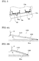
- The sliding slope apparatus can be used (i.e., a wheelchair can be loaded and unloaded) in a normal state in which the slope section is extended to a maximum extent (see
FIG. 6A ), and can also be used in a state in which the slope section is received within another slope section, and comes in contact with the ground (seeFIG. 6B ). In the latter case, however, it may be difficult to handle the wheelchair due to the steepness of the slope. - Specifically, since the slope angle θ(b) is larger than the slope angle θ(a) in a normally extended state, it may be difficult to load and unload the wheelchair.
- In recent years, a slope apparatus that has a reduced height in an upright state from the viewpoint of rearward visibility, and also has a reduced slope angle in an extended state has been desired. This may make it necessary to further divide the sliding slope apparatus into a plurality of slope sections.
- In this case, the difference between the slope angle θ(b) and the slope angle θ(a) further increases.
- The inventor of the invention conducted extensive studies in order to prevent loading of a wheelchair when a sliding slope apparatus is not sufficiently extended.
- A sliding slope apparatus is normally configured so that the base end of a first slope is rotatably connected to a vehicle, and a second slope section (and third slope section) is slidingly extended. Therefore, the inventor focused on the fact that the center of gravity of the slope section moves away from the vehicle when the second slope is extended.
-
JP-A-2006-137320 - However, the torsion bar disclosed in
JP-A-2006-137320 -
JP-A-2004-224086 - However, the technology disclosed in
JP-A-2004-224086 JP-A-2004-224086 - A vehicular slope apparatus of the related art is known from
DE 1 925 442 U - This document discloses a sloping ramp arranged at a vehicle which can be folded down. The energy generated by folding down the sloping ramp is stored in one or several portion springs by which the stored energy can be used again to fold up the sloping ramp.
-
US 5,273,335 A discloses a combination ramp which has also the function of a tail gate for use with pickup trucks and the like. The ramp can be nested into a compact barrier to function as a tail gate and can also be unfolded and extended to function as a ramp from a ground. - An object of the invention is to provide a safe sliding vehicular slope apparatus that makes it possible to easily detect an insufficiently extended state, and prevent a situation in which the slope apparatus is used in a steeply sloping state.
- According to the invention, this object is solved by a vehicular slope apparatus with the features of
claim 1. - According to one aspect of the invention, there is provided a vehicular slope apparatus including a first slope section that is rotatably connected to a body of a vehicle at its base end, and a second slope section that is slidably connected to an extension side of the first slope section, the first slope section including an assistance section that applies an assistance force (Mf) in a direction in which the first slope section rotates upwardly and toward the body around the base end as a rotation center, the assistance force (Mf) being larger than a downward moment that occurs at a center of gravity (M1) of the entire of the vehicular slope apparatus when the entire of the vehicular slope apparatus is horizontalized in a state in which the second slope section is received within the first slope section, and is smaller than a downward moment that occurs at a center of gravity (M2) of the entire of the vehicular slope apparatus when the second slope section is extended from the first slope section to a maximum extent, the center of gravity of the entire slope section continuously changing from the center of gravity M1 to the center of gravity M2 when the second slope section is slidingly extended from the first slope section, and the first slope section rotating when the second slope section has been extended to a predetermined extent so that an end of the vehicular slope apparatus comes in contact with the ground.
- The expression "the second slope section is slidably connected to the extension side of the first slope section" means that the vehicular slope apparatus is configured so that the second slope section is slidingly extended from the first slope section in the direction in which the vehicular slope apparatus is extended from the vehicle. The invention also includes a slope apparatus in which the second slope section is divided into a plurality of slope sections, and each slope section is slidingly extended.
- Since the assistance force (Mf) is larger than the downward moment that occurs at the center of gravity M1 when the entire of the vehicular slope apparatus is horizontalized in a state in which the second slope section is received within the first slope section, the end of the vehicular slope apparatus does not come in contact with the ground GL when the vehicular slope apparatus is rotated away from the vehicle in a state in which the second slope section is not extended (see
FIG. 1 (schematic view)). - The center of gravity of the vehicular slope apparatus moves away from the vehicle when the second slope section is extended from this state.
- Since the assistance force is smaller than the downward moment that occurs at the center of gravity M2 when the second slope section is extended from the first slope section to a maximum extent (see
FIG. 1 ), the end of the vehicular slope apparatus comes in contact with the ground. - Since the invention utilizes the effect whereby the center of gravity of the entire of the vehicular slope apparatus moves away from the vehicle upon extension of the second slope section, the center of gravity of the entire of the vehicular slope apparatus continuously changes from the center of
gravity M 1 to the center of gravity M2 when the second slope section is slidingly extended from the first slope section. - The second slope section is preferably extended from the first slope section within a range of 350 to 1500 mm. In this case, it is preferable that the distance between the rotation center and the center of
gravity M 1 when the second slope section is received within the first slope section differ from the distance between the rotation center and the center of gravity M2 when the second slope section is extended to a maximum extent by 100 mm or more. - The assistance means may be arbitrarily selected insofar as the above effects are obtained.
- The assistance means may be a coil spring, a torsion spring, a combination of a damper structure and a tensile structure, or the like.
- If the assistance means is integrally provided on the vehicular slope apparatus, the degree of freedom of the design of the vehicle on which the vehicular slope apparatus is mounted increases.
- According to the invention, if the second slope section is insufficiently extended, the end of the vehicular slope apparatus does not come in contact with the ground due to the assistance force in the direction in which the vehicular slope apparatus rotates upwardly and toward the interior of the vehicle. Therefore, a situation in which the second slope section is insufficiently extended can be easily observed with the naked eye, and a situation in which the vehicular slope apparatus is used in a steeply sloping state can be prevented.
- When the vehicular slope apparatus has a rear gate connection type structure (i.e., the rear gate (tailgate) of the vehicle is also extended when the vehicular slope apparatus is extended), it is possible to prevent a situation in which design parts such as a bumper cover provided on the rear gate come in contact with the ground or the like (i.e., are damaged) due to the steepness of the slope.
-
-
FIG. 1 illustrates an assistance force setting method according to the invention. -
FIG. 2 is a perspective view illustrating a vehicle when a vehicular slope apparatus according to one embodiment of the invention is extended. -
FIG. 3 is a perspective view illustrating a state in which a vehicular slope apparatus according to one embodiment of the invention is housed in a vehicle. -
FIG. 4 is a perspective view illustrating a state in which a vehicular slope apparatus according to one embodiment of the invention is extended. -
FIG. 5 illustrates an example of the structure of an assistance means. -
FIG.s 6A and 6B are a side view illustrating a related-art vehicular slope apparatus (FIG 6A illustrates a state in which the vehicular slope apparatus is extended, andFIG 6B illustrates a state in which the vehicular slope apparatus comes in contact with the ground in an unextended state). -
- 1
- Vehicular slope apparatus
- 2
- Body
- 4
- Interior
- 10
- First slope section
- 11
- First rail member
- 12, 13, 14
- Floor member
- 20
- Second slope section
- 21
- Second rail member
- 22, 23, 24
- Floor member
- 27
- End (end opposite to vehicle)
- 50
- Coil spring
- Exemplary embodiments of the invention are described below with reference to the drawings.
FIG. 2 is a perspective view illustrating a vehicle equipped with a vehicular slope apparatus.FIG. 2 illustrates a state in which avehicular slope apparatus 1 is extended. Arear door 3 of abody 2 of the vehicle is opened, and a wheelchair (not shown) is loaded into aninterior 4 of the vehicle. - The
vehicular slope apparatus 1 is used to load and unload the wheelchair (not shown) into and from the rear floor inside theinterior 4. Thevehicular slope apparatus 1 is housed upright on the rear side of theinterior 4 when thevehicular slope apparatus 1 is not used (seeFIG. 3 ), and is extended during use so that the end of thevehicular slope apparatus 1 comes in contact with the ground, and the entire of thevehicular slope apparatus 1 slopes gently (seeFIG. 2 ). -
FIG. 4 is a view illustrating a vehicular slope apparatus according to one embodiment of the invention. -
FIG. 4 illustrates a state in which avehicular slope apparatus 1 is extended. - As illustrated in
FIG. 4 , thevehicular slope apparatus 1 includes afirst slope section 10 that is positioned on the side of thebody 2, and asecond slope section 20 that is positioned on the side of the ground G, thefirst slope section 10 and thesecond slope section 20 are adjacent to each other when thevehicular slope apparatus 1 is extended. - The
first slope section 10 includes afirst rail member 11 that is provided on each end of thefirst slope section 10 in the widthwise direction and extends in the slide direction (i.e., the extension direction of the vehicular slope apparatus 1), a ground-side floor member 12, a plurality ofintermediate floor members 13, and a vehicle-side floor member 14, thefloor members first slope section 10. - The
second slope section 20 includes asecond rail member 21 that is provided on each end of thesecond slope section 20 in the widthwise direction and extends in the slide direction, a ground-side floor member 22, a plurality ofintermediate floor members 23, and a vehicle-side floor member 24, thefloor members second slope section 20. - When the
second slope section 20 is received within thefirst slope section 10, the twosecond rail members 21 of thesecond slope section 20 are positioned inside the twofirst rail members 11 of thefirst slope section 10. - Each end of the
floor members first slope section 10 and thefloor members second slope section 20 in the widthwise direction is fitted into a groove that is formed (extends) in each of thefirst rail member 11 and thesecond rail member 21 in the longitudinal direction, and is secured by welding or using a screw. - A wheelchair or the like can be moved over the surface of the floor members (12 to 14 and 22 to 24). The
first rail member 11 and thesecond rail member 21 prevent a situation in which the wheelchair comes off thevehicular slope apparatus 1. - Sliding members formed of a resin material are disposed between the
first rail member 11 and thesecond rail member 21 so that thefirst rail member 11 and thesecond rail member 21 can slide relative to each other. - The sliding members are secured on the ground-side end of each
first rail member 11 and the vehicle-side end of each second rail member 21 (i.e., four sliding members are provided in total). - The
first rail member 11 and thesecond rail member 21 are formed in the shape of a groove or the like by extruding an aluminum alloy, for example. - A stopper section that protrudes inward is formed on the vehicle-side end of each
first rail member 11 of thefirst slope section 10, and limits movement of thesecond slope section 20 relative to thefirst slope section 10 in the slide direction toward thebody 2. - Specifically, the stopper section serves as a stopper mechanism that prevents an excessive slide of the
second slope section 20 when thesecond slope section 20 is received within thefirst slope section 10. - The vehicle-side end of the vehicle-
side floor member 24 of thesecond slope section 20 protrudes downward so that an engagement section is formed. - The engagement section of the
floor member 24 engages an engagement section of thefloor member 12, and limits movement of thesecond slope section 20 relative to thefirst slope section 10 in the slide direction toward the ground G. - Specifically, the engagement section serves as a stopper mechanism that prevents an excessive slide of the
second slope section 20 when thesecond slope section 20 is extended. - The vehicle-side end of the vehicle-
side floor member 24 of thesecond slope section 20 is sloped to form a slope portion, so that a difference in level is reduced when the wheelchair travels. - The ground-side end of the ground-
side floor member 22 of thesecond slope section 20 is sloped to form a slope portion, and anend 27 of thefloor member 22 comes in contact with the ground G when thesecond slope section 20 is extended (lowered). - A buffer member formed of a rubber material is secured on the back side of the
floor member 22 so that thefloor member 22 advantageously comes in contact with the ground G when thesecond slope section 20 is extended (lowered). - A protrusion is formed on the vehicle-side end face of the
floor member 22, and a depression is formed in the ground-side end face of thefloor member 23 adjacent to thefloor member 22. The protrusion is fitted into the depression. - Likewise, a protrusion or a depression is formed on (in) the end face of each floor member (12 to 14 and 22 to 24) so that each protrusion is fitted into the opposite depression.
- An antislip protrusion and depression (hollow) that extend in parallel to the longitudinal direction are integrally formed on (in) the side of each floor member (12 to 14 and 22 to 24) that forms the front surface of the
vehicular slope apparatus 1 by extruding an aluminum alloy, for example. - As illustrated in
FIG. 4 , the vehicle-side floor member 14 of thefirst slope section 10 and ahinge 43 secured on the rear end of the floor inside theinterior 4 are connected so as to be rotatable around a pin 42 (rotation center). - A fitting groove and a depression (hollow) are integrally formed in the
hinge 43 by extruding an aluminum alloy, for example. - A
handle 31 is provided on the ground-side floor member 22 of thesecond slope section 20 in the center area in the widthwise direction. -
FIG. 5 illustrates an example of an assistance means. - A
coil spring 50 is disposed between abody 2a and aback surface 10a of thefirst slope section 10. - The
coil spring 50 is secured on thevehicular slope apparatus 1. An assistance force Mf occurs when oneend 50a of thecoil spring 50 is contacting to thebody 2a. - The assistance means may be implemented by a torsion spring, a tensile mechanism, or the like instead of the coil spring.
- In one embodiment of the invention, the distance between the
pin 42 and the center ofgravity M 1 of the entire of thevehicular slope apparatus 1 is 430 mm when thesecond slope section 20 is received within thefirst slope section 10. The center of gravity M2 of the entire of thevehicular slope apparatus 1 continuously moves away from the vehicle when thesecond slope section 20 is extended, and the distance between thepin 42 and the center of gravity M2 is 780 mm when thesecond slope section 20 is extended to a maximum extent. - Therefore, when the weight of the entire of the
vehicular slope apparatus 1 is 15 kg, the assistance force (Mf) is 64.5 N·m (=M1 (430 mm) x 15 kg) or more and less than 117 N·m (=M2 (780 mm) x 15 kg). - The assistance force is preferably set so that the end of the
vehicular slope apparatus 1 comes in contact with the ground G when thesecond slope section 20 is extended to a predetermined extent, and need not necessarily be set based on the maximum extension of the second slope section. - An example in which one second slope section is provided has been described above. Note that the invention may also be applied to a slide structure that includes a plurality of second slope sections (i.e., the second slope section is divided into a plurality of slope sections).
- The invention may be widely utilized in an industrial field of a slope apparatus that is mounted on and housed in a vehicle and is designed so that a plurality of slope sections are slidingly extended.
Claims (5)
- A vehicular slope apparatus (1) comprising- a first slope section (10) being rotatably connected to a body (2a) of a vehicle at its base end,- a second slope section (20) being connected to an extension side of the first slope section (10),- assistance means for applying an assistance force (Mf) in a direction in which the first slope section (10) rotates upwardly and toward the body (2a) around the base end as a rotation center (42),- wherein the assistance means is disposed between the body (2a) of the vehicle and a back surface of the first slope section (10),characterised in that- the second slope section (20) being slidably connected to the extension side of the first slope section (10) and being extendable between a received position in which the second slope section (20) is received within the first slope section (10) and an extended position, and- the assistance means being adapted to provide a defined assistance force (Mf) being larger than a downward moment that occurs at a center of gravity (M1) of the entire of the vehicular slope apparatus (1) when the entire of the vehicular slope apparatus (1) is horizontalized in a state in which the second slope section (20) is received within the first slope section (10), and is smaller than a downward moment that occurs at a center of gravity (M2) of the entire of the vehicular slope apparatus (1) when the second slope section (20) is extended from the first slope section (10) to a maximum extent, the center of gravity of the entire of the vehicular slope apparatus (1) continuously changing from the center of gravity M1 to the center of gravity M2 when the second slope section (20) is slidingly extended from the first slope section (10), and the first slope section (10) rotating when the second slope section (20) has been extended to a predetermined extent so that an end (27) of the vehicular slope apparatus (1) comes in contact with the ground (G).
- The vehicular slope apparatus according to claim 1,
characterized in that
the assistance means being integrally provided on the vehicular slope apparatus. - The vehicular slope apparatus (1) according to claim 1 or 2,
characterized in that
the second slope section (20) being extended from the first slope section (10) within a range of 350 to 1500 mm. - The vehicular slope apparatus (1) according to any one of claims 1 to 3,
characterized in that
a distance between the rotation center (42) and the center of gravity (M2) being larger than a distance between the rotation center (42) and the center of gravity (M1) by 100 mm or more. - The vehicular slope apparatus (1) according to any one of the claims 1 to 4
characterized in that
for implementing the assistance means a coil spring (50), a torsion spring or a tensile mechanism is provided.
Applications Claiming Priority (1)
| Application Number | Priority Date | Filing Date | Title |
|---|---|---|---|
| PCT/JP2008/073036 WO2010070751A1 (en) | 2008-12-18 | 2008-12-18 | Ramp device for vehicle |
Publications (3)
| Publication Number | Publication Date |
|---|---|
| EP2360055A1 EP2360055A1 (en) | 2011-08-24 |
| EP2360055A4 EP2360055A4 (en) | 2012-07-25 |
| EP2360055B1 true EP2360055B1 (en) | 2013-08-14 |
Family
ID=42268441
Family Applications (1)
| Application Number | Title | Priority Date | Filing Date |
|---|---|---|---|
| EP08878919.3A Not-in-force EP2360055B1 (en) | 2008-12-18 | 2008-12-18 | Ramp device for vehicle |
Country Status (4)
| Country | Link |
|---|---|
| US (1) | US8104128B2 (en) |
| EP (1) | EP2360055B1 (en) |
| CN (1) | CN102256830B (en) |
| WO (1) | WO2010070751A1 (en) |
Families Citing this family (23)
| Publication number | Priority date | Publication date | Assignee | Title |
|---|---|---|---|---|
| WO2014092119A1 (en) | 2012-12-11 | 2014-06-19 | 本田技研工業株式会社 | Mounting device for object to be mounted |
| JP6316103B2 (en) * | 2014-06-06 | 2018-04-25 | 株式会社マツダE&T | Slope for vehicle and vehicle equipped with the same |
| CN104444463B (en) * | 2014-11-05 | 2016-06-08 | 济南轨道交通装备有限责任公司 | The Commercial Vehicle handling engineering truck of railway freight-car double-layered transport vehicles special-purpose vehicle |
| CN104442517B (en) * | 2014-12-08 | 2017-02-01 | 济南轨道交通装备有限责任公司 | Commercial vehicle loading/unloading engineering truck |
| CN106740372B (en) * | 2015-11-20 | 2019-03-15 | 信昌机械厂股份有限公司 | Ramp jack of happiness car |
| CN106314293A (en) * | 2016-09-30 | 2017-01-11 | 张家港市隆旌汽车零部件有限公司 | High-bearing slope structure and car |
| CN106364406A (en) * | 2016-09-30 | 2017-02-01 | 张家港市隆旌汽车零部件有限公司 | Wheelchair accessible vehicle with ramp plate being driven manually |
| BE1024690B1 (en) * | 2016-10-24 | 2018-05-29 | Steve Florquin | Extendable bridge device and truck |
| KR101882671B1 (en) * | 2017-01-12 | 2018-07-27 | 주식회사 팬스타엔터프라이즈 | Variable entry apparatus for automotive lift |
| CN108928326B (en) * | 2017-05-27 | 2022-04-05 | 长城汽车股份有限公司 | Electric vehicle battery pack disassembly and transfer device |
| JP6674488B2 (en) * | 2018-02-13 | 2020-04-01 | 本田技研工業株式会社 | Vehicle slope |
| CN108674465B (en) * | 2018-05-07 | 2020-08-28 | 襄阳信正纺织有限公司 | Portable yarn conveying trolley |
| CN108797263B (en) * | 2018-06-14 | 2020-10-16 | 义乌市诠铈新材料有限公司 | Short step device under wheelchair for orthopedics |
| CN108852666B (en) * | 2018-07-20 | 2020-06-16 | 桂林电子科技大学 | Rail type vehicle-mounted wheelchair |
| CN108819826A (en) * | 2018-08-08 | 2018-11-16 | 中国人民解放军第二七二医院 | A kind of field hospital's operation service truck based on damage control surgery |
| US10821038B2 (en) * | 2018-10-26 | 2020-11-03 | Freedom Motors, Inc. | Ramp system for a motorized vehicle |
| CN109572774A (en) * | 2018-11-23 | 2019-04-05 | 安徽骏泰塑业科技有限公司 | A kind of pvc pipe transport vehicle |
| WO2020256163A1 (en) * | 2019-06-17 | 2020-12-24 | 엘지전자 주식회사 | Artificial intelligence mobile robot and control method therefor |
| CN112744144A (en) * | 2019-10-30 | 2021-05-04 | 爱信轻金属株式会社 | Slope device |
| JP7409283B2 (en) * | 2020-10-22 | 2024-01-09 | トヨタ自動車株式会社 | Vehicle with ramp |
| JP7388383B2 (en) * | 2021-03-26 | 2023-11-29 | トヨタ自動車株式会社 | Vehicles and vehicle operation systems |
| CN116712260B (en) * | 2023-07-27 | 2026-02-03 | 利谙简工业技术(南京)有限公司 | Auxiliary device for getting on or off wheelchair |
| CN117141336A (en) * | 2023-09-05 | 2023-12-01 | 浙江极氪智能科技有限公司 | Trunk step unit and vehicle |
Family Cites Families (15)
| Publication number | Priority date | Publication date | Assignee | Title |
|---|---|---|---|---|
| DE1925442U (en) * | 1965-07-19 | 1965-10-14 | Otto Gaiser Fahrzeugbau Mittel | INCLINED RAMP ON A VEHICLE, IN PARTICULAR LOW-LOADER. |
| JPS5671900U (en) * | 1979-11-09 | 1981-06-13 | ||
| US4479753A (en) * | 1982-05-19 | 1984-10-30 | Transportation Design & Technology, Inc. | Wheelchair lift for passenger vehicles |
| US5273335A (en) * | 1992-11-06 | 1993-12-28 | Philip R. Belnap | Truck ramp/tailgate |
| DE29707803U1 (en) * | 1997-04-30 | 1997-09-18 | Peter Maier Leichtbau GmbH, 78224 Singen | Bridge element, such as tail lift, drive-over bridge or the like. |
| JP2001276133A (en) * | 2000-03-31 | 2001-10-09 | Kanto Auto Works Ltd | Retractable slide slope |
| US6293748B1 (en) * | 2000-06-13 | 2001-09-25 | Pierre Savaria | Storable ramp assembly |
| DE10063652A1 (en) * | 2000-12-20 | 2002-07-25 | Daimler Chrysler Ag | Motor vehicle with loading ramp |
| US6802095B1 (en) * | 2002-01-25 | 2004-10-12 | Ricon Corporation | Ramp assembly having a lift and lock mechanism |
| JP4178048B2 (en) | 2003-01-20 | 2008-11-12 | 株式会社マツダE&T | Vehicle tailgate structure |
| US6834903B2 (en) * | 2003-02-18 | 2004-12-28 | Galen R. Harper | Tailgate ramp system |
| JP2005319886A (en) * | 2004-05-10 | 2005-11-17 | East Japan Railway Co | Wheelchair slope device for railway vehicles |
| JP4180558B2 (en) * | 2004-11-12 | 2008-11-12 | 本田技研工業株式会社 | Vehicle slope structure |
| FR2909319B1 (en) * | 2006-12-05 | 2011-07-01 | Heuliez | BICORPS MONOCORP VEHICLE WITH ROOF ELEMENT MOBILE. |
| US7549692B2 (en) * | 2007-10-31 | 2009-06-23 | Washington Derron K | Ramp assembly for a vehicle tailgate |
-
2008
- 2008-12-18 CN CN200880132395.3A patent/CN102256830B/en active Active
- 2008-12-18 WO PCT/JP2008/073036 patent/WO2010070751A1/en not_active Ceased
- 2008-12-18 EP EP08878919.3A patent/EP2360055B1/en not_active Not-in-force
-
2011
- 2011-06-01 US US13/150,927 patent/US8104128B2/en active Active
Also Published As
| Publication number | Publication date |
|---|---|
| US8104128B2 (en) | 2012-01-31 |
| EP2360055A4 (en) | 2012-07-25 |
| WO2010070751A1 (en) | 2010-06-24 |
| CN102256830B (en) | 2013-10-16 |
| EP2360055A1 (en) | 2011-08-24 |
| CN102256830A (en) | 2011-11-23 |
| US20110225745A1 (en) | 2011-09-22 |
Similar Documents
| Publication | Publication Date | Title |
|---|---|---|
| EP2360055A1 (en) | Ramp device for vehicle | |
| US10562456B2 (en) | Front bumper slide-out step | |
| US10752201B2 (en) | Hinge arrangement | |
| US12005006B2 (en) | Moveable baseplate cover and inboard barrier gate of a lift system for a motorized vehicle | |
| US6109675A (en) | Hinged member for a rear impact guard | |
| US8511734B2 (en) | Deployable tailgate ramp | |
| US20060214386A1 (en) | Automated deployable running board | |
| US20190389386A1 (en) | Running board with roof access step and method | |
| CA2519048A1 (en) | Retractable step | |
| BRPI0615733B1 (en) | ASSEMBLY OF AUTOMOTIVE PEST PROTECTION COVER HINGES | |
| JP2009234530A (en) | Vehicular slope device | |
| CZ20014043A3 (en) | Front bonnet arrangement and four-point suspension | |
| CN111788352A (en) | Base unit of erectable barrier and erectable barrier comprising said base unit | |
| CN114075903A (en) | Sliding tail gate, vehicle and tail gate | |
| CN108688600A (en) | Active roll-over | |
| US6814378B1 (en) | Retractable safety bumper apparatus | |
| JP5723513B2 (en) | Slope device for vehicle | |
| US20190055767A1 (en) | System for opening a tailgate having a plurality of opening kinematics | |
| EP2008848B2 (en) | Motor vehicle roof | |
| KR102791705B1 (en) | Lower door garnish structure | |
| JP4834494B2 (en) | Slope device for vehicle | |
| KR101987486B1 (en) | Step system for vehicle | |
| EP2857266B1 (en) | Hinge arrangement | |
| US9248780B2 (en) | Vehicle access apparatus and a method thereof | |
| JPH1149036A (en) | Flip-up hood |
Legal Events
| Date | Code | Title | Description |
|---|---|---|---|
| PUAI | Public reference made under article 153(3) epc to a published international application that has entered the european phase |
Free format text: ORIGINAL CODE: 0009012 |
|
| 17P | Request for examination filed |
Effective date: 20110601 |
|
| AK | Designated contracting states |
Kind code of ref document: A1 Designated state(s): AT BE BG CH CY CZ DE DK EE ES FI FR GB GR HR HU IE IS IT LI LT LU LV MC MT NL NO PL PT RO SE SI SK TR |
|
| DAX | Request for extension of the european patent (deleted) | ||
| A4 | Supplementary search report drawn up and despatched |
Effective date: 20120627 |
|
| RIC1 | Information provided on ipc code assigned before grant |
Ipc: A61G 3/06 20060101ALI20120621BHEP Ipc: B60P 1/43 20060101ALI20120621BHEP Ipc: B60R 3/02 20060101AFI20120621BHEP |
|
| RIC1 | Information provided on ipc code assigned before grant |
Ipc: B60P 1/43 20060101ALI20130204BHEP Ipc: B60R 3/02 20060101AFI20130204BHEP Ipc: A61G 3/06 20060101ALI20130204BHEP |
|
| GRAP | Despatch of communication of intention to grant a patent |
Free format text: ORIGINAL CODE: EPIDOSNIGR1 |
|
| GRAS | Grant fee paid |
Free format text: ORIGINAL CODE: EPIDOSNIGR3 |
|
| GRAA | (expected) grant |
Free format text: ORIGINAL CODE: 0009210 |
|
| AK | Designated contracting states |
Kind code of ref document: B1 Designated state(s): AT BE BG CH CY CZ DE DK EE ES FI FR GB GR HR HU IE IS IT LI LT LU LV MC MT NL NO PL PT RO SE SI SK TR |
|
| REG | Reference to a national code |
Ref country code: GB Ref legal event code: FG4D |
|
| REG | Reference to a national code |
Ref country code: CH Ref legal event code: EP Ref country code: AT Ref legal event code: REF Ref document number: 626599 Country of ref document: AT Kind code of ref document: T Effective date: 20130815 |
|
| REG | Reference to a national code |
Ref country code: IE Ref legal event code: FG4D |
|
| REG | Reference to a national code |
Ref country code: DE Ref legal event code: R096 Ref document number: 602008026882 Country of ref document: DE Effective date: 20131010 |
|
| REG | Reference to a national code |
Ref country code: NL Ref legal event code: VDEP Effective date: 20130814 Ref country code: AT Ref legal event code: MK05 Ref document number: 626599 Country of ref document: AT Kind code of ref document: T Effective date: 20130814 |
|
| REG | Reference to a national code |
Ref country code: LT Ref legal event code: MG4D |
|
| PG25 | Lapsed in a contracting state [announced via postgrant information from national office to epo] |
Ref country code: PT Free format text: LAPSE BECAUSE OF FAILURE TO SUBMIT A TRANSLATION OF THE DESCRIPTION OR TO PAY THE FEE WITHIN THE PRESCRIBED TIME-LIMIT Effective date: 20131216 Ref country code: AT Free format text: LAPSE BECAUSE OF FAILURE TO SUBMIT A TRANSLATION OF THE DESCRIPTION OR TO PAY THE FEE WITHIN THE PRESCRIBED TIME-LIMIT Effective date: 20130814 Ref country code: IS Free format text: LAPSE BECAUSE OF FAILURE TO SUBMIT A TRANSLATION OF THE DESCRIPTION OR TO PAY THE FEE WITHIN THE PRESCRIBED TIME-LIMIT Effective date: 20131214 Ref country code: CY Free format text: LAPSE BECAUSE OF FAILURE TO SUBMIT A TRANSLATION OF THE DESCRIPTION OR TO PAY THE FEE WITHIN THE PRESCRIBED TIME-LIMIT Effective date: 20130626 Ref country code: HR Free format text: LAPSE BECAUSE OF FAILURE TO SUBMIT A TRANSLATION OF THE DESCRIPTION OR TO PAY THE FEE WITHIN THE PRESCRIBED TIME-LIMIT Effective date: 20130814 Ref country code: LT Free format text: LAPSE BECAUSE OF FAILURE TO SUBMIT A TRANSLATION OF THE DESCRIPTION OR TO PAY THE FEE WITHIN THE PRESCRIBED TIME-LIMIT Effective date: 20130814 Ref country code: SE Free format text: LAPSE BECAUSE OF FAILURE TO SUBMIT A TRANSLATION OF THE DESCRIPTION OR TO PAY THE FEE WITHIN THE PRESCRIBED TIME-LIMIT Effective date: 20130814 Ref country code: NO Free format text: LAPSE BECAUSE OF FAILURE TO SUBMIT A TRANSLATION OF THE DESCRIPTION OR TO PAY THE FEE WITHIN THE PRESCRIBED TIME-LIMIT Effective date: 20131114 |
|
| PG25 | Lapsed in a contracting state [announced via postgrant information from national office to epo] |
Ref country code: PL Free format text: LAPSE BECAUSE OF FAILURE TO SUBMIT A TRANSLATION OF THE DESCRIPTION OR TO PAY THE FEE WITHIN THE PRESCRIBED TIME-LIMIT Effective date: 20130814 Ref country code: LV Free format text: LAPSE BECAUSE OF FAILURE TO SUBMIT A TRANSLATION OF THE DESCRIPTION OR TO PAY THE FEE WITHIN THE PRESCRIBED TIME-LIMIT Effective date: 20130814 Ref country code: FI Free format text: LAPSE BECAUSE OF FAILURE TO SUBMIT A TRANSLATION OF THE DESCRIPTION OR TO PAY THE FEE WITHIN THE PRESCRIBED TIME-LIMIT Effective date: 20130814 Ref country code: BE Free format text: LAPSE BECAUSE OF FAILURE TO SUBMIT A TRANSLATION OF THE DESCRIPTION OR TO PAY THE FEE WITHIN THE PRESCRIBED TIME-LIMIT Effective date: 20130814 Ref country code: GR Free format text: LAPSE BECAUSE OF FAILURE TO SUBMIT A TRANSLATION OF THE DESCRIPTION OR TO PAY THE FEE WITHIN THE PRESCRIBED TIME-LIMIT Effective date: 20131115 Ref country code: SI Free format text: LAPSE BECAUSE OF FAILURE TO SUBMIT A TRANSLATION OF THE DESCRIPTION OR TO PAY THE FEE WITHIN THE PRESCRIBED TIME-LIMIT Effective date: 20130814 |
|
| PG25 | Lapsed in a contracting state [announced via postgrant information from national office to epo] |
Ref country code: CY Free format text: LAPSE BECAUSE OF FAILURE TO SUBMIT A TRANSLATION OF THE DESCRIPTION OR TO PAY THE FEE WITHIN THE PRESCRIBED TIME-LIMIT Effective date: 20130814 |
|
| PG25 | Lapsed in a contracting state [announced via postgrant information from national office to epo] |
Ref country code: SK Free format text: LAPSE BECAUSE OF FAILURE TO SUBMIT A TRANSLATION OF THE DESCRIPTION OR TO PAY THE FEE WITHIN THE PRESCRIBED TIME-LIMIT Effective date: 20130814 Ref country code: RO Free format text: LAPSE BECAUSE OF FAILURE TO SUBMIT A TRANSLATION OF THE DESCRIPTION OR TO PAY THE FEE WITHIN THE PRESCRIBED TIME-LIMIT Effective date: 20130814 Ref country code: NL Free format text: LAPSE BECAUSE OF FAILURE TO SUBMIT A TRANSLATION OF THE DESCRIPTION OR TO PAY THE FEE WITHIN THE PRESCRIBED TIME-LIMIT Effective date: 20130814 Ref country code: CZ Free format text: LAPSE BECAUSE OF FAILURE TO SUBMIT A TRANSLATION OF THE DESCRIPTION OR TO PAY THE FEE WITHIN THE PRESCRIBED TIME-LIMIT Effective date: 20130814 Ref country code: EE Free format text: LAPSE BECAUSE OF FAILURE TO SUBMIT A TRANSLATION OF THE DESCRIPTION OR TO PAY THE FEE WITHIN THE PRESCRIBED TIME-LIMIT Effective date: 20130814 Ref country code: DK Free format text: LAPSE BECAUSE OF FAILURE TO SUBMIT A TRANSLATION OF THE DESCRIPTION OR TO PAY THE FEE WITHIN THE PRESCRIBED TIME-LIMIT Effective date: 20130814 |
|
| PG25 | Lapsed in a contracting state [announced via postgrant information from national office to epo] |
Ref country code: ES Free format text: LAPSE BECAUSE OF FAILURE TO SUBMIT A TRANSLATION OF THE DESCRIPTION OR TO PAY THE FEE WITHIN THE PRESCRIBED TIME-LIMIT Effective date: 20130814 Ref country code: IT Free format text: LAPSE BECAUSE OF FAILURE TO SUBMIT A TRANSLATION OF THE DESCRIPTION OR TO PAY THE FEE WITHIN THE PRESCRIBED TIME-LIMIT Effective date: 20130814 |
|
| PLBE | No opposition filed within time limit |
Free format text: ORIGINAL CODE: 0009261 |
|
| STAA | Information on the status of an ep patent application or granted ep patent |
Free format text: STATUS: NO OPPOSITION FILED WITHIN TIME LIMIT |
|
| 26N | No opposition filed |
Effective date: 20140515 |
|
| REG | Reference to a national code |
Ref country code: CH Ref legal event code: PL |
|
| REG | Reference to a national code |
Ref country code: DE Ref legal event code: R097 Ref document number: 602008026882 Country of ref document: DE Effective date: 20140515 |
|
| PG25 | Lapsed in a contracting state [announced via postgrant information from national office to epo] |
Ref country code: LU Free format text: LAPSE BECAUSE OF FAILURE TO SUBMIT A TRANSLATION OF THE DESCRIPTION OR TO PAY THE FEE WITHIN THE PRESCRIBED TIME-LIMIT Effective date: 20131218 |
|
| REG | Reference to a national code |
Ref country code: IE Ref legal event code: MM4A |
|
| PG25 | Lapsed in a contracting state [announced via postgrant information from national office to epo] |
Ref country code: IE Free format text: LAPSE BECAUSE OF NON-PAYMENT OF DUE FEES Effective date: 20131218 Ref country code: LI Free format text: LAPSE BECAUSE OF NON-PAYMENT OF DUE FEES Effective date: 20131231 Ref country code: CH Free format text: LAPSE BECAUSE OF NON-PAYMENT OF DUE FEES Effective date: 20131231 |
|
| PG25 | Lapsed in a contracting state [announced via postgrant information from national office to epo] |
Ref country code: MC Free format text: LAPSE BECAUSE OF FAILURE TO SUBMIT A TRANSLATION OF THE DESCRIPTION OR TO PAY THE FEE WITHIN THE PRESCRIBED TIME-LIMIT Effective date: 20130814 |
|
| PG25 | Lapsed in a contracting state [announced via postgrant information from national office to epo] |
Ref country code: TR Free format text: LAPSE BECAUSE OF FAILURE TO SUBMIT A TRANSLATION OF THE DESCRIPTION OR TO PAY THE FEE WITHIN THE PRESCRIBED TIME-LIMIT Effective date: 20130814 |
|
| PG25 | Lapsed in a contracting state [announced via postgrant information from national office to epo] |
Ref country code: BG Free format text: LAPSE BECAUSE OF FAILURE TO SUBMIT A TRANSLATION OF THE DESCRIPTION OR TO PAY THE FEE WITHIN THE PRESCRIBED TIME-LIMIT Effective date: 20130814 Ref country code: HU Free format text: LAPSE BECAUSE OF FAILURE TO SUBMIT A TRANSLATION OF THE DESCRIPTION OR TO PAY THE FEE WITHIN THE PRESCRIBED TIME-LIMIT; INVALID AB INITIO Effective date: 20081218 |
|
| PG25 | Lapsed in a contracting state [announced via postgrant information from national office to epo] |
Ref country code: MT Free format text: LAPSE BECAUSE OF FAILURE TO SUBMIT A TRANSLATION OF THE DESCRIPTION OR TO PAY THE FEE WITHIN THE PRESCRIBED TIME-LIMIT Effective date: 20130814 |
|
| REG | Reference to a national code |
Ref country code: FR Ref legal event code: PLFP Year of fee payment: 8 |
|
| REG | Reference to a national code |
Ref country code: FR Ref legal event code: PLFP Year of fee payment: 9 |
|
| PGFP | Annual fee paid to national office [announced via postgrant information from national office to epo] |
Ref country code: GB Payment date: 20161222 Year of fee payment: 9 |
|
| PGFP | Annual fee paid to national office [announced via postgrant information from national office to epo] |
Ref country code: FR Payment date: 20161221 Year of fee payment: 9 |
|
| PGFP | Annual fee paid to national office [announced via postgrant information from national office to epo] |
Ref country code: DE Payment date: 20161227 Year of fee payment: 9 |
|
| REG | Reference to a national code |
Ref country code: DE Ref legal event code: R082 Ref document number: 602008026882 Country of ref document: DE Representative=s name: WUNDERLICH & HEIM PATENTANWAELTE PARTNERSCHAFT, DE |
|
| REG | Reference to a national code |
Ref country code: DE Ref legal event code: R119 Ref document number: 602008026882 Country of ref document: DE |
|
| GBPC | Gb: european patent ceased through non-payment of renewal fee |
Effective date: 20171218 |
|
| REG | Reference to a national code |
Ref country code: FR Ref legal event code: ST Effective date: 20180831 |
|
| PG25 | Lapsed in a contracting state [announced via postgrant information from national office to epo] |
Ref country code: DE Free format text: LAPSE BECAUSE OF NON-PAYMENT OF DUE FEES Effective date: 20180703 Ref country code: FR Free format text: LAPSE BECAUSE OF NON-PAYMENT OF DUE FEES Effective date: 20180102 |
|
| PG25 | Lapsed in a contracting state [announced via postgrant information from national office to epo] |
Ref country code: GB Free format text: LAPSE BECAUSE OF NON-PAYMENT OF DUE FEES Effective date: 20171218 |