EP2359159B1 - Système radar sar - Google Patents
Système radar sar Download PDFInfo
- Publication number
- EP2359159B1 EP2359159B1 EP08878158.8A EP08878158A EP2359159B1 EP 2359159 B1 EP2359159 B1 EP 2359159B1 EP 08878158 A EP08878158 A EP 08878158A EP 2359159 B1 EP2359159 B1 EP 2359159B1
- Authority
- EP
- European Patent Office
- Prior art keywords
- target
- sar
- velocity
- targets
- iteration
- Prior art date
- Legal status (The legal status is an assumption and is not a legal conclusion. Google has not performed a legal analysis and makes no representation as to the accuracy of the status listed.)
- Active
Links
- 238000012545 processing Methods 0.000 claims description 155
- 230000001133 acceleration Effects 0.000 claims description 132
- 238000000034 method Methods 0.000 claims description 128
- 230000033001 locomotion Effects 0.000 claims description 78
- 238000001514 detection method Methods 0.000 claims description 71
- 230000008569 process Effects 0.000 claims description 68
- 238000004364 calculation method Methods 0.000 claims description 24
- 230000001965 increasing effect Effects 0.000 claims description 15
- 238000010200 validation analysis Methods 0.000 claims description 9
- 238000011156 evaluation Methods 0.000 claims description 8
- 239000012634 fragment Substances 0.000 claims description 6
- 230000000977 initiatory effect Effects 0.000 claims description 4
- 230000015572 biosynthetic process Effects 0.000 claims description 3
- 230000004927 fusion Effects 0.000 claims description 3
- 230000010365 information processing Effects 0.000 claims description 3
- 230000009977 dual effect Effects 0.000 claims description 2
- 239000013598 vector Substances 0.000 description 15
- 230000014509 gene expression Effects 0.000 description 14
- 230000004044 response Effects 0.000 description 12
- 230000008859 change Effects 0.000 description 9
- 230000010354 integration Effects 0.000 description 9
- 230000000694 effects Effects 0.000 description 6
- 238000002310 reflectometry Methods 0.000 description 5
- 230000008901 benefit Effects 0.000 description 4
- 238000007792 addition Methods 0.000 description 3
- 238000010586 diagram Methods 0.000 description 3
- 238000006073 displacement reaction Methods 0.000 description 3
- 238000005516 engineering process Methods 0.000 description 3
- 238000003384 imaging method Methods 0.000 description 3
- 238000005259 measurement Methods 0.000 description 3
- 230000035945 sensitivity Effects 0.000 description 3
- 230000003595 spectral effect Effects 0.000 description 3
- 238000012360 testing method Methods 0.000 description 3
- 238000005755 formation reaction Methods 0.000 description 2
- 230000003068 static effect Effects 0.000 description 2
- 238000012935 Averaging Methods 0.000 description 1
- 230000001427 coherent effect Effects 0.000 description 1
- 230000007812 deficiency Effects 0.000 description 1
- 230000001419 dependent effect Effects 0.000 description 1
- 238000011161 development Methods 0.000 description 1
- 230000002708 enhancing effect Effects 0.000 description 1
- 238000010348 incorporation Methods 0.000 description 1
- 230000006698 induction Effects 0.000 description 1
- 230000010363 phase shift Effects 0.000 description 1
- 230000002035 prolonged effect Effects 0.000 description 1
- 238000000926 separation method Methods 0.000 description 1
- 230000007480 spreading Effects 0.000 description 1
- 238000012956 testing procedure Methods 0.000 description 1
- 230000009466 transformation Effects 0.000 description 1
- 230000007704 transition Effects 0.000 description 1
- 239000011800 void material Substances 0.000 description 1
Images
Classifications
-
- G—PHYSICS
- G01—MEASURING; TESTING
- G01S—RADIO DIRECTION-FINDING; RADIO NAVIGATION; DETERMINING DISTANCE OR VELOCITY BY USE OF RADIO WAVES; LOCATING OR PRESENCE-DETECTING BY USE OF THE REFLECTION OR RERADIATION OF RADIO WAVES; ANALOGOUS ARRANGEMENTS USING OTHER WAVES
- G01S13/00—Systems using the reflection or reradiation of radio waves, e.g. radar systems; Analogous systems using reflection or reradiation of waves whose nature or wavelength is irrelevant or unspecified
- G01S13/88—Radar or analogous systems specially adapted for specific applications
- G01S13/89—Radar or analogous systems specially adapted for specific applications for mapping or imaging
- G01S13/90—Radar or analogous systems specially adapted for specific applications for mapping or imaging using synthetic aperture techniques, e.g. synthetic aperture radar [SAR] techniques
- G01S13/9021—SAR image post-processing techniques
- G01S13/9029—SAR image post-processing techniques specially adapted for moving target detection within a single SAR image or within multiple SAR images taken at the same time
-
- G—PHYSICS
- G01—MEASURING; TESTING
- G01S—RADIO DIRECTION-FINDING; RADIO NAVIGATION; DETERMINING DISTANCE OR VELOCITY BY USE OF RADIO WAVES; LOCATING OR PRESENCE-DETECTING BY USE OF THE REFLECTION OR RERADIATION OF RADIO WAVES; ANALOGOUS ARRANGEMENTS USING OTHER WAVES
- G01S13/00—Systems using the reflection or reradiation of radio waves, e.g. radar systems; Analogous systems using reflection or reradiation of waves whose nature or wavelength is irrelevant or unspecified
- G01S13/88—Radar or analogous systems specially adapted for specific applications
- G01S13/89—Radar or analogous systems specially adapted for specific applications for mapping or imaging
- G01S13/90—Radar or analogous systems specially adapted for specific applications for mapping or imaging using synthetic aperture techniques, e.g. synthetic aperture radar [SAR] techniques
- G01S13/9004—SAR image acquisition techniques
- G01S13/9017—SAR image acquisition techniques with time domain processing of the SAR signals in azimuth
-
- G—PHYSICS
- G01—MEASURING; TESTING
- G01S—RADIO DIRECTION-FINDING; RADIO NAVIGATION; DETERMINING DISTANCE OR VELOCITY BY USE OF RADIO WAVES; LOCATING OR PRESENCE-DETECTING BY USE OF THE REFLECTION OR RERADIATION OF RADIO WAVES; ANALOGOUS ARRANGEMENTS USING OTHER WAVES
- G01S13/00—Systems using the reflection or reradiation of radio waves, e.g. radar systems; Analogous systems using reflection or reradiation of waves whose nature or wavelength is irrelevant or unspecified
- G01S13/66—Radar-tracking systems; Analogous systems
- G01S13/72—Radar-tracking systems; Analogous systems for two-dimensional tracking, e.g. combination of angle and range tracking, track-while-scan radar
-
- G—PHYSICS
- G01—MEASURING; TESTING
- G01S—RADIO DIRECTION-FINDING; RADIO NAVIGATION; DETERMINING DISTANCE OR VELOCITY BY USE OF RADIO WAVES; LOCATING OR PRESENCE-DETECTING BY USE OF THE REFLECTION OR RERADIATION OF RADIO WAVES; ANALOGOUS ARRANGEMENTS USING OTHER WAVES
- G01S13/00—Systems using the reflection or reradiation of radio waves, e.g. radar systems; Analogous systems using reflection or reradiation of waves whose nature or wavelength is irrelevant or unspecified
- G01S13/88—Radar or analogous systems specially adapted for specific applications
- G01S13/89—Radar or analogous systems specially adapted for specific applications for mapping or imaging
- G01S13/90—Radar or analogous systems specially adapted for specific applications for mapping or imaging using synthetic aperture techniques, e.g. synthetic aperture radar [SAR] techniques
- G01S13/904—SAR modes
- G01S13/9092—SAR modes combined with monopulse techniques
Definitions
- the present invention relates to the field of Synthetic Aperture Radar (SAR) and addresses radar imaging from an aircraft of ground targets which may be stationary or moving on the ground.
- SAR Synthetic Aperture Radar
- SAR as such is a well-known technology, by which it is possible with a radar device mounted on a moving platform to obtain a much finer angular resolution of the stationary ground than will be furnished by the radar antenna. This refinement is achieved by storing radar data over a length of time and adopting the fact that during this time the radar has registered the ground from many different positions.
- a SAR processor mathematically transforms these radar data into a SAR image of the ground, which has the angular resolution of an antenna aperture, corresponding to the flight path along which data were stored.
- the SAR radar located on a platform e.g. on an aircraft or a satellite moves along a nominal straight path and illuminates a large ground area by means of an antenna.
- High range resolution pulses are transmitted from the antenna and the return signal from the ground is received by the antenna and recorded along the straight path.
- signal processing high resolution is accomplished both along and transversely of the straight path.
- a condition for this is that the position of the antenna is known or can be calculated within a fraction of the resolution and that the amplitude and phase of the transmitted and received radar signals are known.
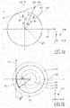
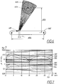
- Figures 1a and 1b illustrate the fundamental ambiguity of SAR as regards moving targets on ground.
- a moving target is henceforth meant an object moving across the ground, the object being known as regards its general properties, e.g. radar cross section order of magnitude and its general pattern of motion, but its actual presence and state of motion are to be determined by the radar measurement.
- a moving target can as a special case be stationary, with its velocity relative to ground being zero. Henceforth in the description a moving target is including also this special case.
- FIG. 1a shows with a first arrow 103 a trajectory fora stationary ground point and with a second arrow 104 the trajectory of a moving target, which are mapped into the same pair, R , ⁇ , of SAR image polar coordinates.
- the two trajectories differ by a rigid rotation ⁇ around a z-axis in the rest frame of the SAR platform being located at the origin 105.
- the axes symbol 108 illustrates the different axes including the z-axis.
- Figure 1a thus illustrates movements of ground targets relative a fixed SAR platform.
- the SAR platform can equally well be considered moving relative ground in the direction of the X-axis 101.
- the y-axis 102 is thus perpendicular to the path of the SAR-platform.
- the angle ⁇ is negative as the true position 106 is oriented in negative angle direction, i.e. anti-clockwise, in relation to the apparent position 107.
- Figure 1b is a vector diagram with velocity in the direction of the movement of the SAR platform on an ⁇ - axis 110 and velocity in a perpendicular direction on an ⁇ - axis 111.
- the axes symbol 118 shows the different velocity axes, ⁇ , ⁇ and ⁇ with velocities in the x, y and z directions.
- Figure 1b shows a velocity vector 112 of a moving target in the ground frame, i.e. the movement relative to the ground.
- a moving target velocity vector 117 with velocity in relation to the SAR platform, will have its end point on a circle 113 of diameter 2 V , V being the velocity of the moving SAR platform relative to ground.
- a ground point velocity vector - V (in figure 1b shown as - V ) represents the velocity of a ground point in relation to the moving SAR platform. Varying the processing velocity parameter V ⁇ W, and processing the SAR image to contain coordinates ⁇ outside the region of the antenna footprint any moving target will be depicted as having an apparent position in the SAR image at point R , ⁇ for the proper selection of W . With the processing velocity W the moving target velocity vector will lie on the dotted circles 114-116 in figure 1b .
- the angle ⁇ is the rigid rotation shown also in figure 1a . When the angle ⁇ becomes zero the velocity in the y-direction will be zero.
- f R ⁇ ⁇ ⁇ T T F r R , ⁇ t , t dt
- T radar registration time
- r R , ⁇ ( t ) is the range history of the particular ground point R
- ⁇ . f ( R , ⁇ ) is the SAR-image.
- each ground point R , ⁇ will follow the path of uniform linear motion in the rest frame of the aircraft.
- r R , ⁇ t R sin ⁇ ⁇ Vt e X + R cos ⁇ e Y + H e Z assuming the aircraft to be heading in the x - direction (all coordinates will be in the SAR platform frame - upper case letters refer to the position of moving targets at time zero and other motion constants, lower case letters to coordinates and variables in general, letters in bold represents vectors, e x , e y and e z are basis vectors in x, y and z directions.
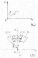
- the polar coordinates R , ⁇ are defined in figure 2 with the basis vectors defining the axes in space.
- the polar coordinate angle ⁇ is thus an angle in clockwise direction starting from the e y -axis.
- H is the platform altitude over ground and will be assumed constant and known just as the platform velocity V, t is time.
- r R , ⁇ ( t )
- r R , ⁇ ( t ) which is the absolute value of the r R , ⁇ ( t )-vector, so the range history is r R , ⁇ t R sin ⁇ Vt 2 + R 2 cos 2 ⁇ + H 2
- Expression (1) has a most important implication, namely that any target having the range history r R , ⁇ ( t ) will become located in the SAR image in R , ⁇ . Hence if there is an ambiguity (as there may be) in that several targets have the same range history r R , ⁇ ( t ), the responses from these targets will all be superimposed in R , ⁇ regardless of the actual target coordinates.
- the presence of a moving target can be obtained with the desired degree of confidence as the retrieved amplitude will be considerably increased at the presence of a moving target.
- it is possible to detect a moving target in this way due to the aforementioned ambiguities it is not possible to estimate all the parameters of its motion.
- FIG. 3 shows the apparent position 301 of a moving target in a SAR-image at R , ⁇ .
- the angle ⁇ is here negative as it is oriented in anti-clockwise direction from the y-axis.
- the angle ⁇ is positive in figure 3 , in contrast to figure 1a , as the true position 302 here is oriented in positive angle direction, i.e. clockwise, in relation to the apparent position 301.
- the true position 302 of the moving target is located at R , ⁇ + ⁇ as explained in association with figure 1a .
- the SAR platform with the antenna is located at some point 303 along the z-axis.
- the antenna footprint 304 on the ground, i.e. the area on the ground illuminated by the antenna, is illustrated as an area with a line pattern in figure 3 . In the example of figure 3 the true position of the moving target will thus be moved to an apparent position in the SAR image outside the antenna footprint.
- the SAR image coordinates R , ⁇ and the true position R , ⁇ + ⁇ are related by the angle ⁇ , which together with the velocity parameter W determine the ground velocity vector.
- the SAR image containing moving targets is seen to take the shape of a first angular sector 305 shown without a line pattern, which spreads an angle of approximately 10°, corresponding to a maximum value of ⁇ for ground velocity ⁇ 50 m/s and a SAR platform ground velocity of 300 m/s.
- This can be calculated from expression (8) which gives that the velocity of the moving target in relation to the ground, in this example 50m/s, divided with the velocity of the SAR platform in relation to ground, in this example 300 m/s approximately equals ⁇ in radians.
- the velocity ratio becomes 1/6, which thus corresponds to ⁇ being 1/6 of a radian or 10 degrees.
- the maximum width of the first angular sector 305, in this example, is thus 10 degrees valid for true positions of moving targets positioned at the borderline of the antenna footprint.
- the angle ⁇ in figure 3 is exaggerated for clarity reasons.
- the spread will for the same reasons result in a second angular sector 306.
- the sector covered by the antenna footprint 304 which contains the ground clutter, a relatively high SAR resolution is required for moving targets to exhibit sufficient clutter SNR (Signal to Noise Ratio) with respect to the ground clutter in the SAR image. Outside the clutter area, i.e.
- the SAR image is free from ground clutter and moving target detection can be obtained at lower SAR resolution. Detection at such lower resolution allows data to be reduced after which improved resolution and moving target parameter accuracy can be achieved with small processing effort.
- moving targets typically move at velocities an order of magnitude smaller than the aircraft velocity V it follows from expression (8), and is plainly seen in figure 1b , that these moving targets must move in a direction close to the y - direction in order to appear as misplaced stationary ground features in the SAR image.
- the angle ⁇ will thus be just a few degrees. It may still correspond to a significant misplacement of the moving target in the SAR image since the distance from the radar to the target can be large.
- the accumulated signal energy backscattered from the target into the radar will correspond to the intensity of the target in the SAR image.
- targets will not move in such a way that they only cause misplacement effects in the SAR image.
- the moving targets will be defocused in the sense that they appear smeared and with lower intensity in the SAR image as compared to cases when they are focused, i.e. the cases discussed so far.
- generally moving targets will be both misplaced and defocused.
- ground targets move in the x-direction at slow velocities they will be defocused.
- This defocusing effect is significantly less strong than the misplacement effect, and will not be noticeable when resolution is coarse.
- targets slowly moving in the x-direction remain focused if the resolution is coarse.
- such a motion may however have the effect of making targets defocused to such a degree that they become invisible in the SAR image.
- GMTI Greenwich Mean Time At coarse SAR resolution moving targets remain focused, though they are generally misplaced.
- GMTI is the established method to detect and position moving targets.
- GMTI uses several radar channels, related to different phase centres distributed over the actual radar antenna. Any location on the ground will correspond to a certain phase shift between the phase centres. By using two such channels it is thus possible to cancel the ground response coming from any particular point on the ground.
- the GMTI channels By using the GMTI channels to produce a combined SAR image which cancels the ground response at some point on the ground, will cause a moving target being positioned by the SAR process to this point to have a true position somewhere where the ground return cancellation does not apply. Thus it will be highlighted in the combined SAR image. Providing the same combined SAR image for two further channels, the true position of the highlighted moving target can be determined.
- HR SAR high resolution SAR
- a major shortcoming of the GMTI is that the method is based on coarse resolution SAR images. In typical GMTI applications, several targets may be situated within the same resolution cell and for this reason it will not be possible to preserve moving target individuality when the moving targets pass each other at close ranges.
- HR SAR has poor performance with respect to moving targets.
- SAR resolution is very high, even very small velocity fluctuations will make the targets strongly defocused, or even invisible. Since targets in the process of stopping or starting must change velocity they will always be out of focus and quite likely invisible in HR SAR.
- US 6441772 B1 discloses a Low frequency SAR radar system.
- the invention describes a method to process SAR data with so called Fast Factorized Back projection (FFB) and a solution for detecting moving targets.
- FFB Fast Factorized Back projection
- the method proposed in US 6441772 B1 is based on FFB for SAR focusing of linearly moving targets, incorporating FFB SAR imaging of the stationary ground as a special case.
- FFB Fast Factorized Back projection
- M.I. Pettersson "Detection of moving targets in wideband SAR", IEEE Transactions on Aerospace and Electronic Systems, vol. 40, no. 3, 1 July 2004, pages 780-796, XP055171752, ISSN: 00189251, DOI: 10.1109/TAES.2004.1337454 relates to detection of moving targets in wideband SAR and describes a system which uses Fast Factorized Back projection.
- This object is achieved by providing a method performed in a radar system for detecting targets comprising moving and stationary targets.
- the radar system is equipped with Synthetic Aperture Radar, SAR, onboard a SAR platform (601), comprising navigation equipment for accurate determination of the position of the SAR platform (601), and which is transversing a stationary ground region and targets in the said ground region, in which the SAR platform (601) obtains radar data by means of at least one antenna.
- the movement of the SAR platform (601) during recording of the data is essentially rectilinear and uniform in an azimuth direction, and its velocity significantly larger than those of the moving targets.
- the radar system further comprises a SAR processor recording the radar data and the position of the antenna or antennas for each transmitted radar pulse, wherein within synthetic sub-apertures (306-309), each sub-aperture covering a surveyed region (605) is a part of the stationary ground region, radar data are:
- the method is characterized by that the linear combination comprises a relation of coordinates of target positions in said neighbouring SAR images such that related coordinates indicate the same target position at a given reference time for all targets having a specific relative velocity with respect to the moving SAR platform and a specific degree of acceleration in the direction orthogonal to the movement of the SAR platform, wherein
- the SAR images in each iteration step are formed for all relative velocities which are conceivable for the moving targets and all such small accelerations, which are considered consistent with keeping the velocity of the moving target constant over time, and that this is performed by letting the SAR image resolution and the density of velocity and acceleration assumptions increase with increasing iteration level to an extent such that SAR image pairs will remain related by related coordinates corresponding to the same target position at the SAR resolution of any iteration level by selecting the closest assumption within the set of assumptions for velocity and acceleration for each target made at this particular iteration level.
- a ⁇ determination process being accomplished by said antennas having a first and a second phase centre displaced in the azimuth direction by a distance larger than the characteristic wavelength of the radar system and smaller than the range resolution and where each phase centre is feeding data into a separate receiver channel and where by forming SAR images from data from each channel, these two SAR images being related by related coordinates corresponding to the same target position by selecting the closest assumption for velocity and acceleration for each target, a phase difference between the two SAR images for each target position represents an angle ⁇ , defined as the ⁇ -parameter, between a true and an apparent position of the target, and thus enables a complete determination of the state of motion of the target.
- the surveillance area is extended to the surveyed region by using outputs from the motion insensitive process, the target detection process and the target positioning process by calculating SAR-images in the immediate surroundings in R , ⁇ , ⁇ , W -space of each track.
- the moving targets for a selected patch are detected by first conducting all iterations in the loop A requiring only just one velocity and acceleration assumption for all conceivable target velocities and accelerations and that the information from the A-loop is fed into two parallel processing paths:
- one cycle of the processing steps ex-clutter and ex-clutter-iteration is defined as a D-loop and that one cycle of the processing steps in the first and the second paths together with the processing step CFAR is defined as a C-loop and further in that the C-loop is repeated at least for two cycles, the C-loop defining the target detection process.
- a B2-loop comprises:
- the extended surveillance process comprises processing in a continuously repeated B1-loop information available from outputs of the B2-loop and the A-loop and where one cycle of the B1-loop comprises the following processing steps performed in series:
- a GPS system is used to calculate the position of the SAR platform and the antenna or antennas.
- the object is further achieved by providing a radar system equipped with Synthetic Aperture Radar, SAR, onboard a SAR platform, comprising navigation equipment for accurate determination of the position of the SAR platform.
- the radar system is arranged for detecting targets comprising moving or stationary targets and for transversing a stationary ground region and targets in the said ground region, in which the SAR platform is arranged to obtain radar data by means of at least one antenna.
- the SAR platform is arranged to move essentially rectilinear and uniform in an azimuth direction with a velocity significantly larger than those of the moving targets during recording of the data.
- the radar system comprises further a SAR processor arranged to record the radar data and the position of the antenna or antennas for each transmitted radar pulse.
- the linear combination comprises a relation of coordinates of target positions in said neighbouring SAR images such that related coordinates are arranged to indicate the same target position at a given reference time for all targets having a specific relative velocity with respect to the moving SAR platform and a specific degree of acceleration in the direction orthogonal to the movement of the SAR platform
- the object is also achieved by providing a SAR processor used for calculating the detection and positioning of targets comprising moving or stationary targets according to the method in claims 1-16.
- the invention proposes an improved method and radar system for moving target detection which in one implementation of the invention is capable of detecting ordinary moving targets with X-band (3 cm wavelength) radar at practical surveillance ranges (50 km).
- the invention is concerned with detecting targets comprising moving or stationary targets with a radar system equipped with Synthetic Aperture Radar, SAR, onboard a SAR platform.
- the SAR platform comprises navigation equipment for accurate determination of the SAR platform position, and is transversing a stationary ground region and targets in the said ground region, in which the SAR platform obtains radar data by means of at least one antenna.
- the movement of the SAR platform during recording of the data is essentially rectilinear and uniform in an azimuth direction, and its velocity significantly larger than those of the moving targets.
- the radar system further comprises a SAR processor recording the radar data and the position of the antenna or antennas for each transmitted radar pulse.
- a typical operating frequency of the radar system is around 10 GHz. However also other frequencies can be used, given the restrictions specific to any frequency, or equivalent wavelength, implied by the mathematical rules of the invention described herein.
- the basic SAR-transform expression (1) can be implemented in a SAR processor in many forms, which all makes its execution numerically different and more or less efficient.
- Most implementations rely on Fast Fourier Transforms (FFTs).
- FFTs Fast Fourier Transforms
- direct evaluation of expression (1) in the time domain is substituted by algebraic manipulations in the frequency domain.
- the processing effort for a SAR image of length M samples is of the order M 2 ⁇ 2 log M additions, the majority of which are the evaluation of forward and inverse FFTs. The larger the number of samples, the bigger the SAR image.
- the present invention is a development of a previous invention, namely so-called Fast Factorized Back projection FFB described in US 6441772 B1 .
- That invention set forth a way of processing SAR images by keeping to the time domain of expression (1), viz. avoiding FFTs, in the implementation, in such a way that no more than M 2 ⁇ 2 log M additions are required.
- time domain The advantage with keeping to the time domain is that it allows incorporation of processing adjustments in a way that the spectral domain does not. Such adjustments may for instance be exact compensations for a non-straight or even unknown aircraft registration path. Spectral domain methods to perform these adjustments tend to become highly approximate and not applicable when fractional resolution (resolution compared to the wavelength of the radar) is high. Moreover time domain methods are also applicable for focusing moving ground targets. In particular the present invention will be the adaption of FFB to achieve exactly this.
- FFB FFB
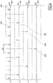
- FFB is based on iterative merging in N iteration steps of "synthetic sub-apertures", each sub-aperture covering a surveyed region being a part of the stationary ground region.
- a sub-aperture is a synthetic sub-aperture of the antenna achieved by storing radar data received by the antenna over a length of time during the movement of the SAR platform in azimuth direction. This has the effect of increasing the length of the antenna aperture, thus achieving a synthetic sub-aperture of the antenna with an increased length.
- the polar coordinates are assumed to have their origin at the midpoint of the corresponding sub-aperture.
- the coordinates of the new SAR image have their origin at the midpoint of the merged sub-apertures, viz. at the end point of the first and the startpoint of the second.
- the coordinates R , ⁇ and R ⁇ , ⁇ ⁇ stands in the relation that related coordinates indicate the same ground position at a given reference time.
- First sub-apertures 306 at the first iteration level 301 are merged pair wise into second sub-apertures 307 at the second iteration level 302.
- the second sub-apertures 307 are then merged pair wise to third sub-apertures 308 at the third iteration level 303.
- Finally the third sub-apertures 308 are merged pair wise to fourth sub-apertures 309 at the fourth iteration level 304.
- the total SAR image reconstruction thus runs in N + 1 steps starting by identifying data F j ( R , ⁇ ) turning into f 0, j ( R , ⁇ ) and ending the reconstruction with the single function f N ,0 )( R , ⁇ ), which is the finished SAR image corresponding to f 3,0 ( R , ⁇ ) and the fourth sub-aperture 309 in the example of figure 3 .
- the iteration process can be summarized as follows:
- accelerations ⁇ mover in an extended FFB chain for moving target focusing as a remedy the acceleration sensitivity.
- L l 2 l WD / V ⁇ ⁇ is the aperture length with respect to the moving target at iteration level l.
- Equation (14) concludes that - unless compensated for - moving target acceleration in the y -direction causes an angular defocusing of the position of the moving target in the SAR image if the displacement due to the acceleration is greater than the angular resolution.
- contributions to the target amplitude, for different moments of time spread in the angular direction in the SAR image by the angular rate: ⁇ ⁇ ⁇ y ⁇ mover W
- the tolerance of the velocity parameter W is obtained by considering the maximum ground velocity w of a target moving in the x -direction (i.e. parallel to the motion of the aircraft), which does not cause defocusing of the target, i.e. the velocity w is within the resolution in the x -direction.
- This target is brought to rest in the SAR image by adjusting W ⁇ W + w , whereas it moves in the opposite direction on limit of defocusing by adjusting W ⁇ W + 2 w.
- ⁇ meaning equivalent to.
- the tolerances may of course be broken for shorter intervals of time, which would mean that at some instances, the state of motion of a ground moving target will change so rapidly that the target cannot be detected. Note however that retardations or accelerations as such, do not prevent detection. For detectability, they must however be sufficiently constant.
- ground moving target accelerations Just as for velocities there is a span of probable ground moving target accelerations, which limits the variation of ⁇ l , i.e. the variation of ⁇ at iteration level l.
- Ground moving target accelerations need only to be considered when they are lower than some value - say 1 m/s 2 - since higher accelerations will be of short duration.
- the accelerations ⁇ mover must accordingly be varied with an interval ⁇ 1 m/s 2 around a zero mean and ⁇ l correspondingly varied.
- the invention proposes the use of FFB, extended by multiple acceleration and velocity assumptions as described, to enable ground moving target detection without any clutter cancellation.
- This method will have the aforementioned advantages of capacity against very slow moving targets as well as moving targets in the state of smooth starting and stopping.
- the method thereby imposes limitations on registration time and thus on other performance parameters as well.
- Moving target detection by the extended FFB method splits into two basic cases, namely:
- the SAR image will contain stationary clutter superimposed on the target response whereas in the second case the target response will occupy a part of the SAR image void of stationary clutter.
- Case 1 In the first case, a sufficient resolution for detection in the presence of ground clutter must be achieved within the available registration time. HR SAR resolution much finer than the target size is normally called for in order to achieve good ground target detection performance. However for stationary targets high resolution is required to discriminate the true targets (such as stationary vehicles) from false targets (e.g. terrain formations) by shape. In contrast, if the SAR process only had the purpose of discriminating the targets from false alarms caused by speckle, the resolution corresponding to the target size would be sufficient. A multi-look procedure based on this resolution smoothens out the speckle fluctuations. Speckle is the statistic variation of SAR-image pixel amplitudes due to multiplicative noise. A pixel is the discrete element of the digital SAR image representation. Multi-look is statistical averaging of pixel amplitudes from several consecutive SAR registrations.
- Target detection for moving targets can thus be modeled on multi-look processing:
- the criterion determining that any strong response is a moving target is that the motion parameters determined by SAR focusing constitute a continuous chain over time, viz. that detections support a target track.
- the described moving target detection method is limited by three parameters, viz. wavelength, aircraft velocity and range, which together must satisfy that sufficient ground resolution x res at iteration level l, defined as x l is achieved in the allotted integration time 2 T l 4 T l x l ⁇ ⁇ R 2 + H 2 V
- x l is achieved in the allotted integration time 2 T l 4 T l x l ⁇ ⁇ R 2 + H 2 V
- ⁇ B the computer burden for HR SAR processing in 10 iterations.
- the burden of each iteration and for each velocity/acceleration assumption computation is ⁇ B /10.
- the number of single velocity/acceleration assumption computations in the extended FFB, at each iteration follows from the following table 1: l L l 2 T l x l ⁇ W l ⁇ ⁇ l # ⁇ W l # ⁇ ⁇ l ⁇ # [m] [s] [m] [m/s] [m/s 2 ] [m/s 3 ] 0 3,1E-01 1,0E-03 2,4E+03 2,3E+06 1,4E+04 1,4E+07 1 1 1 1 6,2E-01 2,1E-03 1,2E+03 5,9E+05 3,5E+03 1,7E+06 1 1 1 2 1,2E+00 4,1E-03 6,0E+02 1,5E+05 8,8E+02 2,1E+05 1 1 1 3 2,5E+00 8,3E-03 3,
- the velocity parameter W l must thus be varied within an interval of ⁇ 25 m/s . This means that when ⁇ W l becomes less than 50 m/s, more than one velocity assumption is needed.
- the acceleration of moving targets are assumed to be lower than 1 m/s 2 since higher accelerations will be of short duration, i.e. the acceleration interval is within 2 m/s 2 .
- ⁇ ⁇ l 8
- ⁇ ⁇ l 0,21 m/s 2
- ten acceleration assumptions thus covers 2,1 m/s 2 which is above the maximum interval of 2 m/s 2 .
- the total number of computations of velocity and acceleration assumptions ⁇ # is then calculated as the product of velocity and acceleration assumptions in order to have all combinations of velocity and acceleration.
- the assumptions thus represent all conceivable combinations of velocity and accelerations for a moving target.
- the velocity is restricted to a specific relative velocity with respect to the moving SAR platform as defined in association with table 1.
- the acceleration is restricted to a specific degree of acceleration in the direction orthogonal to the movement of the SAR platform as defined in association with table 1.
- the accelerations should be sufficiently small to be considered consistent with keeping the velocity of the moving target constant over time.
- the restrictions on acceleration changes are derived in equations (14) and (24).
- the linear combination mentioned above comprises a relation of coordinates of target positions in SAR image pairs.
- Related coordinates R , ⁇ and R ⁇ , ⁇ ⁇ indicate the same target position at a given reference time for all targets having a specific relative velocity with respect to the moving SAR platform and a specific degree of acceleration in the direction orthogonal to the movement of the SAR platform.
- the overall sum of single velocity/acceleration assumption computations is 258, which means that the computational burden is 25.8 times larger than single assumption SAR processing attaining 5 m azimuth resolution.
- the SAR image will extend in azimuth angle far beyond the antenna footprint as depicted in figure 3 .
- detections can be made before the process is split in several assumptions, viz. at iteration stage 6. Therefore the processing burden is set by the SAR image size, which is determined by the antenna footprint as in ordinary HR SAR.
- the SAR images in each iteration step are thus formed for all relative velocities which are conceivable for the moving targets and all such small accelerations, which are considered consistent with keeping the velocity of the moving target constant over time. This is performed by letting the SAR image resolution and the density of velocity and acceleration assumptions increase with increasing iteration level to an extent such that SAR image pairs will remain related by related coordinates corresponding to the same target position at the SAR resolution of any iteration level, by selecting the closest assumption within the set of assumptions for velocity and acceleration for each target made at this particular iteration level.
- N is the number of iteration steps.
- the multi-assumption moving target detection SAR method proposed has about the same processing power requirements as single assumption HR SAR operating at this higher resolution.
- the core of the invention is the method of focusing SAR images to moving vehicles by selecting processing parameters tuned to the moving targets' state of motion by the methods presented above.
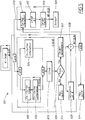
- Figure 5 provides a graphical view of the method, with a conceived imaging geometry shown in figure 6 .
- Figure 5 shows a tracker structure 501 comprising a structure of processing for detection and tracking of moving targets by multi-beam SAR focusing (cf. figure 6 ).
- the flow chart of figure 5 refers to an example with small ground patches (1 sqkm) of the total surveillance area (100 sqkm), each of which is about square sized and contained in the radar antenna footprint.
- a surveyed region comprising 100 patches and the antenna pattern comprises e.g. 10 beams with 10 range intervals for each beam thus making up 100 sub-regions of the ground covered by the multi-beam radar, each sub-region covering a patch.
- Each beam is thus covering 10 patches as each beam has 10 range intervals.
- the flow chart contains five loops A, B1, B2, C and D.
- Loops C and D are sub loops within the loop B2. The time periods for one cycle of each loop, for the example considered with 9 iteration steps, are given in the flow chart.
- Loop A performs the initial extended FFB iteration levels 0 - 6 according to table 1 in about 0,06 seconds. Loop A is a motion insensitive sub process of the extended FFB as only one velocity and one acceleration assumption is required. Loop A is continuously repeated over the total surveillance area (or the surveyed region 605, see figure 6 ).
- m ⁇ N there are thus m iteration steps, m ⁇ N , performed covering the surveyed region where data from one velocity computation at each iteration level using velocity increments ⁇ W l of a processing velocity W , and data from one acceleration computation for acceleration increments ⁇ ⁇ l are used in the motion insensitive process comprising the A-loop for producing one SAR- image of the stationary ground points and the targets per iteration level.
- m 6.
- N - m further iteration steps are then performed for a selected patch (604, see figure 6 ) being a part of the surveyed region (605, see figure 6 ).
- Each iteration step uses a target detection process at each iteration level with data from at least three computations, comprising at least one velocity computation with the velocity increments ⁇ W l and at least one acceleration computation with the acceleration increments ⁇ ⁇ l for producing one SAR-image per combination of velocity and acceleration computation and for detecting targets and target tracks as well as calculating target parameters R , ⁇ , a processing velocity W and an acceleration ⁇ in a direction perpendicular to the azimuth direction, the R , ⁇ , ⁇ , W -parameters defining an R , ⁇ , ⁇ , W -space for each target.
- the obtained data from the A-loop is in this example processed further at iteration levels 7 - 9 in the loop B2 for one selected patch.
- the loop B2 in the example of figure 5 , has been performed for the selected patch after about 5 s, a new patch is selected and the loop B2 is performed for this patch.
- the B2 loop is then repeated for each of the 100 patches, i.e. it will take about 500 s to run through all 100 patches.
- Loop B2 starts with receiving SAR processing results from loop A comprising iteration steps 0-6, for a first patch.
- the moving targets for the selected patch are detected by first conducting all iterations in the A-loop requiring only one velocity and acceleration assumption for all conceivable target velocities and accelerations.
- the information from the A-loop is fed into two parallel processing paths, a first path and a second path.
- the first path comprises ex-clutter targets, i.e. targets which have an apparent position outside an antenna footprint (304) defining the boundaries of the SAR image of stationary ground, but a true position within the selected patch. This corresponds to targets moving relatively fast in order to achieve a sufficient misplacement to move the apparent position from one patch to another.
- the ex-clutter targets are possible to detect through a CFAR tresholding scheme in processing step ex-clutter CFAR (502), prior to further motion sensitive iteration steps, in this example iteration steps 7-9, which are then conducted in processing step ex-clutter iteration (503) only for the SAR image fragments and velocity and acceleration parameter assumptions which are in the immediate vicinity of the position, velocity and acceleration parameters of the detected targets. These further iteration steps enhance the accuracy of motion parameter determination of the detections made in processing step ex-clutter 502. The processing burden for achieving this accuracy is however small.
- One cycle of processing steps ex-clutter 502 and ex-clutter iteration 503 comprises a D-loop with a cycle time of 0,53 s in the example of figure 5 .
- One cycle of the processing steps in the first and the second paths together with a processing step CFAR (505) is defined as a C-loop.
- the C-loop is repeated at least for two cycles and defines the target detection process.
- the second path comprises in-clutter targets, i.e. targets which have an apparent and true position inside the antenna footprint (304) defining the boundaries of the SAR image of stationary ground.
- in-clutter targets i.e. targets which have an apparent and true position inside the antenna footprint (304) defining the boundaries of the SAR image of stationary ground.
- further in-clutter iterations (504), in this example iteration steps 7-9, involving processing of the entire SAR image of the surveyed region must be performed, thus improving resolution.
- Processing steps 502-505 comprises the loop C which in this example with 9 iterations takes about 0,53 s corresponding to the time to fly the synthetic aperture length at the tenth iteration level, i.e. after 9 iterations, see table 1.
- the loop C corresponding to the main step 1 for target detection, is then repeated 10 times, main step 2, and parameters for detected target candidates are fed to the processing step track 506 for target validation.
- One batch p of target parameters is produced for each C-loop cycle.
- the target positioning process comprises processing information from the C-loop in the processing step, track (506), where detected target candidates are analysed according to a track validation algorithm in order to detect valid target tracks.
- the track validation algorithm is performed according to equations (28) and (29).
- Target parameters for valid tracks are fed to a processing step, target parameters (507), and invalid target tracks causes the selection of a new patch (514) and initiation of a new C-loop for this new patch.
- a new patch is selected for processing.
- the detected target parameters comprising R , ⁇ , ⁇ , W from processing step, target parameters (507), are fed to processing steps, target data (508) and calculation of ⁇ (509).
- calculation of ⁇ (509) target positioning for detected targets are calculated by determining a ⁇ -parameter according to a ⁇ determination process.
- the ⁇ determination process uses equation (33) for calculation of the ⁇ -parameter.
- the processing results from processing step, calculation of ⁇ (509) are fed to the processing step, target data (508).
- the processing results comprising the detected target parameters R , ⁇ , ⁇ , W and ⁇ available in the processing step, target data (508), is thus the result of a target detection and positioning process comprising information processing in the C-loop and in the processing steps, track (506), target parameters (507) and calculation of ⁇ (509), one cycle of which is defined as the B2-loop.
- the completion of the B2-loop initiates the start up of a new C-loop for a new selected patch (514) using loop A data as input.
- detected targets are analysed according to equations (28) and (29) in order to detect valid target tracks.
- the target parameters included in valid tracks are fed to the processing step 507, target parameters.
- the detected target parameters comprising R , ⁇ , ⁇ , W from the processing step target parameters 507 are fed to the processing steps 508, target data, and 509, calculation of ⁇ .
- target positioning for detected targets is calculated by determining the ⁇ -parameter according to equation (33) as will be further explained below.
- the processing results from the processing step calculation of ⁇ , 509 are fed to the processing step target data, 508.
- the processing results comprising the detected target parameters R mover , ⁇ mover , ⁇ mover , ⁇ mover and ⁇ of validated target tracks, form a complete description of the state of motion of moving ground targets, are now available in processing step target data, 508, from which they are fed to loop B1.
- the target detection and positioning loop B2 comprising processing steps 502-509, is now completed for the first patch and loop A data are used to initiate for a new patch in loop B2.
- the target positioning process is a sub part of the B2 loop, comprising the processing steps track 506, target parameters 507, calculation of ⁇ 509 and target data 508. In this process the target position within the patch is calculated by determining the ⁇ -parameter representing the relative velocity of the target in relation to the moving SAR platform.
- Each combination of velocity and acceleration computations performed in the B2 loop represents an assumption of possible target parameters.
- Data fed from the loop B2 are used as initial data in the loop B1 which requires initial data in the form of the target parameters R mover , ⁇ mover , ⁇ mover , ⁇ mover and ⁇ in current or previous patches.
- the B1 loop comprising processing steps 511-513 in series, is run for the surveyed region for all detected targets. For each 0,53 s cycle of the B1 loop a B1-output 520 comprises updated and thus continuously validated target tracks and positions for the surveyed region.
- the surveillance area is extended to the surveyed region by using outputs from the motion insensitive process, the target detection process and the target positioning process by calculating SAR-images in the immediate surroundings in R , ⁇ , ⁇ , W -space of each track.
- the extended surveillance process comprises processing in the continuously repeated B1-loop, information available from outputs of the B2-loop and the A-loop and where one cycle of the B1-loop comprises the following processing steps performed in series:
- the revisit rime for target detection in a certain patch is thus 530 s.
- a radar system of monopulse type having an adjacent radar channel besides the ordinary one.
- Each channel is connected to a separate phase center on the radar antenna.
- the adjacent channel antenna phase center displaced some small distance ⁇ x along the (negative) x - axis or azimuth direction.
- the two channels obtain simultaneous radar data which are fed into the SAR processor producing one SAR image for each channel.
- the distance ⁇ x is assumed to be large compared to the operating wavelength ⁇ of the radar system but small compared to both range and azimuth resolution.
- FIG. 6 is a top view showing a preferred geometry for moving target tracking by multi-beam radar.
- the SAR platform 601 uses a racecourse track pattern 602 and a side-looking antenna with its beam pattern centred at an approximate distance of 50 km perpendicular to the flight path and along the ground surface. This distance is defined as the stand-off distance 603.
- the antenna is assumed capable of receiving multiple beams in parallel.
- a set of square 1 sqkm patches 604 are updated as the aircraft moves along its track.
- An update of a certain patch according to the loop C and parallel updates of the surveyed region according to loop B1 will take place with an interval of 0,53 s in our example with 10 iteration levels (9 iteration steps).
- This update interval of 0,53 s corresponds to a distance L l of 160 m, see table 1 for iteration step 9.
- the subdivision of the surveyed region into patches set by range and angular intervals as in the figure will be similar from update to update but will correspond to different pieces of the ground as the aircraft moves along its track.
- An approximately circular 100 sqkm large surveyed complete region 605 will be covered by such sets of patches at all times.
- Equation (33) defines the ⁇ determination criteria.
- the symbol ⁇ stands for phase angle. This means that in equation (33) a phase angle is calculated from multiplication of the two complex expressions f ( R , ⁇ )* and f ( R , ⁇ ).
- the ⁇ determination process comprises the calculation of the angle ⁇ through calculation of the angular phase difference between the two SAR images by multiplying the SAR image f '( R , ⁇ ) from the adjacent radar channel in the coordinates of the ordinary channel with the SAR image conjugate f ( R , ⁇ )* from the ordinary channel according to equation (33), thus receiving as a result a phase angle corresponding to the angle ⁇ also called the ⁇ -parameter being representative of the relative velocity of the target in relation to the moving SAR platform.
- the angle ⁇ can thus be determined by the ⁇ determination process being accomplished by the antennas in the monopulse radar having a first and a second phase centre displaced in the azimuth direction by a distance larger than the characteristic wavelength of the radar system and smaller than the range resolution.
- Each phase centre is feeding data into a separate receiver channel.
- SAR images By forming SAR images from data from each channel, these two SAR images will become related by related coordinates corresponding to the same target position by selecting the closest assumption for velocity and acceleration for each target.
- a phase difference between the two SAR images for each target position represents the angle ⁇ , or the ⁇ - parameter, between a true and an apparent position of the target, and thus enables a complete determination of the state of motion of the target. Therefore it will be possible by the two channels to measure both the state of motion and the target position at a certain reference time of the SAR image, according to equation (16).
- the accuracy ⁇ in the determination of position and velocity in x- and y-coordinates and directions for a moving target is determined by the following set of formulas ⁇ y mover ⁇ ⁇ ⁇ R / 2 ⁇ x mover ⁇ R ⁇ 2 2 + R ⁇ 2 ⁇ x ⁇ mover ⁇ ⁇ ⁇ W 2 2 + W ⁇ 2 ⁇ y ⁇ mover ⁇ ⁇ ⁇ ⁇ W 2 2 + W ⁇ 2 obtained from equation (16).
- the accuracy obtainable for ⁇ is a matter of the influence of the noise which is superimposed on the target response, viz. the target SNR.
- the noise can be the defocused ground response or the thermal noise depending on whether the measurement is "inclutter” or "exclutter” ("Case1" and "Case 2" as desribed above).
- vehicle targets have an RCS (Radar Cross Section) of 5 - 50 sqm (square meter).
- RCS Radar Cross Section
- Figure 7 shows the accuracy of the velocity and position motion parameters in the considered example as function of the velocity ⁇ mover in m/s on an X-axis 701.
- Y-axis 702 shows velocity accuracy in m/s and distance and angular accuracy in m.
- Continuous curves are for small vehicles (personal cars, RCS 5 sqm) and the interrupted curves are for large vehicles (RCS 50 sqm). Following curves are shown:
- the method provides further advantages over combined HR SAR and GMTI for moving target detection/tracking.
- the present method will keep track of these individuals with very high performance. This is so because their individuality is kept as long as they are assigned different parameters R , ⁇ in the SAR image.
- the value ⁇ is set by a combination of moving target velocity and position as explained before.
- ⁇ is determined with such a high accuracy (cf. figure 7 ) that it even when two targets move close together (which may be a matter of a few meters) and at close velocity (the velocity difference may be less 1 m/s) it is likely that they will be assigned different value of R , ⁇ .
- a GPS system is used to calculate the position of the SAR platform and the antenna or antennas.
- the invention is exemplified with an example of 10 iteration levels, certain numbers and sizes of patches and a certain velocity, height and pattern of SAR platform movement as well as a certain value of the stand-off distance. Other values of these parameters can of course be chosen within the scope of the invention.
- the invention comprises a method for detecting targets comprising moving or stationary targets with a radar system equipped with Synthetic Aperture Radar, SAR, onboard a SAR platform as described above.
- the invention also comprises the corresponding radar system.
- the radar system is equipped with a Synthetic Aperture Radar, SAR, onboard a SAR platform comprising navigation equipment for accurate determination of the position of the SAR platform.
- the radar system is arranged for detecting targets comprising moving or stationary targets and for transversing a stationary ground region and targets in the said ground region, in which the SAR platform is arranged to obtain radar data by means of at least one antenna.
- the SAR platform is arranged to move essentially rectilinear and uniform in an azimuth direction with a velocity significantly larger than those of the moving targets during recording of the data.
- the radar system further comprises a SAR processor arranged to record the radar data and the position of the antenna or antennas for each transmitted radar pulse. Wherein, within synthetic sub-apertures each sub-aperture is arranged to cover a surveyed region being a part of the stationary ground region, radar data are:
- the radar system comprises an antenna upholding one or multiple simultaneous beams and also providing dual phase centres.
- the invention also comprises a SAR processor used for calculating the detection and positioning of targets comprising moving or stationary targets according to the method in claims 1-11.
Landscapes
- Engineering & Computer Science (AREA)
- Remote Sensing (AREA)
- Radar, Positioning & Navigation (AREA)
- Physics & Mathematics (AREA)
- Electromagnetism (AREA)
- Computer Networks & Wireless Communication (AREA)
- General Physics & Mathematics (AREA)
- Signal Processing (AREA)
- Radar Systems Or Details Thereof (AREA)
Claims (18)
- Procédé mis en oeuvre dans un système radar pour détecter des cibles comprenant des cibles en mouvement et stationnaires, le système radar étant équipé d'un radar à synthèse d'ouverture, SAR, embarqué dans une plate-forme SAR (601), ladite plate-forme comprenant un équipement de navigation pour une détermination précise de la position de la plate-forme SAR (601) et traversant une région au sol stationnaire et des cibles dans ladite région au sol, dans lequel la plate-forme SAR (601) obtient des données radar au moyen d'au moins une antenne, le mouvement de la plate-forme SAR (601) pendant l'enregistrement des données étant essentiellement rectiligne et uniforme dans une direction d'azimut et sa vitesse étant significativement plus grande que celles des cibles en mouvement, le système radar comprenant en outre un processeur SAR enregistrant les données radar et la position de l'antenne ou des antennes pour chaque impulsion radar transmise, dans lequel au sein de sous-ouvertures synthétiques (306-309), chaque sous-ouverture couvrant une région étudiée (605) faisant partie de la région au sol stationnaire, des données radar sont :• successivement fusionnées en N étapes d'itération en images SAR de résolution croissante de la région étudiée (605) et où• chaque étape d'itération consiste à former une nouvelle image SAR à un nouveau niveau d'itération (301-304) par une combinaison linéaire d'images SAR voisines dans l'étape d'itération précédente,ledit procédé étant caractérisé
en ce que la combinaison linéaire comprend une relation de coordonnées de positions de cible dans lesdites images SAR voisines de telle sorte que des coordonnées apparentées indiquent la même position de cible à un temps de référence donné pour toutes les cibles ayant une vitesse relative spécifique par rapport à la plate-forme SAR en mouvement et un degré spécifique d'accélération dans la direction orthogonale au mouvement de la plate-forme SAR, dans lequel• m étapes d'itération, m<N, sont mises en oeuvre couvrant la région étudiée (605) où des données provenant d'un calcul de vitesse à chaque niveau d'itération en utilisant des incréments de vitesse ΔWℓ d'une vitesse de traitement W, et des données provenant d'un calcul d'accélération pour des incréments d'accélération Δÿℓ sont utilisées dans un processus insensible au mouvement répété de façon continue sur la région étudiée (605), dans lequel chaque cycle est défini en tant que boucle A, pour produire une image SAR des points au sol stationnaires et des cibles par niveau d'itération et• N - m autres étapes d'itération sont mises en oeuvre pour une parcelle sélectionnée (604) faisant partie de la région étudiée (605), chaque étape d'itération utilisant un processus de détection de cible à chaque niveau d'itération avec des données provenant d'au moins trois calculs, comprenant au moins un calcul de vitesse avec les incréments de vitesse ΔWℓ et au moins un calcul d'accélération avec les incréments d'accélération Δÿℓ pour produire une image SAR par combinaison de calcul de vitesse et d'accélération et pour détecter des cibles et trajectoires de cible ainsi que calculer des paramètres de cible R,Φ, une vitesse de traitement W et une accélération ÿ dans une direction perpendiculaire à la direction d'azimut, les paramètres R,Φ,ÿ,W définissant un espace R,Φ,ÿ,W pour chaque cible et• dans un processus de positionnement de cible, la position de cible au sein de la parcelle est calculée par détermination du paramètre φ représentatif d'une vitesse relative de la cible par rapport à la plate-forme SAR en mouvementoù chaque combinaison de calculs de vitesse et d'accélération représente une hypothèse de paramètres de cible possibles. - Procédé selon la revendication 1, caractérisé en ce que les images SAR dans chaque étape d'itération sont formées pour toutes les vitesses relatives qui sont concevables pour les cibles en mouvement et toutes les petites accélérations de ce type, qui sont considérées cohérentes en gardant la vitesse de la cible en mouvement constante au fil du temps et en ce que celui-ci est mis en oeuvre en laissant la résolution d'image SAR et les hypothèses de densité de vitesse et d'accélération augmenter avec un niveau d'itération croissant à un degré tel que des paires d'images SAR resteront apparentées par des coordonnées apparentées correspondant à la même position de cible à la résolution SAR de n'importe quel niveau d'itération en sélectionnant l'hypothèse la plus proche au sein de l'ensemble d'hypothèses pour la vitesse et l'accélération pour chaque cible faites à ce niveau d'itération particulier.
- Procédé selon les revendications 1 ou 2, caractérisé par un processus de détermination de φ étant accompli par lesdites antennes ayant un premier et un deuxième centre de phase déplacés dans la direction d'azimut d'une distance plus grande que la longueur d'onde caractéristique du système radar et plus petite que la résolution de portée et où chaque centre de phase fournit des données dans un canal récepteur séparé et où en formant des images SAR à partir de données provenant de chaque canal, ces deux images SAR étant apparentées par des coordonnées apparentées correspondant à la même position de cible en sélectionnant l'hypothèse la plus proche pour la vitesse et l'accélération pour chaque cible, une différence de phase entre les deux images SAR pour chaque position de cible représente un angle φ, défini en tant que paramètre φ, entre une position réelle et une position apparente de la cible et permet ainsi une détermination complète de l'état de mouvement de la cible.
- Procédé selon l'une quelconque des revendications 1 à 3, caractérisé en ce que dans un processus de surveillance étendue, la zone de surveillance est étendue à la région étudiée (605) en utilisant des sorties provenant du processus insensible au mouvement, du processus de détection de cible et du processus de positionnement de cible en calculant des images SAR dans les environs immédiats dans un espace R,Φ,ÿ,W de chaque trajectoire.
- Procédé selon l'une quelconque des revendications 1 à 4, caractérisé en ce que les cibles en mouvement pour une parcelle sélectionnée (604) sont détectées en effectuant d'abord toutes les itérations dans la boucle A n'exigeant qu'une seule hypothèse de vitesse et d'accélération pour toutes les vitesses et accélérations concevables de cible et en ce que les informations provenant de la boucle A sont fournies dans deux trajets de traitement parallèles :• dans un premier trajet comprenant des cibles hors écho parasite, c'est-à-dire des cibles qui ont une position apparente à l'extérieur d'une empreinte d'antenne (304) définissant les limites de l'image SAR du sol stationnaire mais une position réelle à l'intérieur de la parcelle sélectionnée, les cibles hors écho parasite pouvant être détectées par l'intermédiaire d'un schéma de seuillage CFAR dans l'étape de traitement CFAR hors écho parasite (502), avant d'autres étapes d'itération sensibles à un mouvement qui sont ensuite réalisées dans l'étape de traitement d'itération hors écho parasite (503) uniquement pour les fragments d'image SAR et les hypothèses de paramètres de vitesse et d'accélération qui sont au voisinage immédiat des paramètres de position, de vitesse et d'accélération des cibles détectées• dans un deuxième trajet comprenant des cibles en écho parasite, c'est-à-dire des cibles qui ont une position apparente et réelle à l'intérieur de l'empreinte d'antenne (304) définissant les limites de l'image SAR du sol stationnaire et pour lesquelles d'autres itérations en écho parasite (504), impliquant un traitement de l'image SAR entière de la région étudiée (605) doivent être mises en oeuvre, améliorant ainsi la résolutiondans lequel les deux trajets sont suivis par une fusion de données et une autre évaluation CFAR dans l'étape de traitement CFAR (505) résultant en la détermination complète d'état de mouvement pour des détections formant des candidats de cible en mouvement.
- Procédé selon la revendication 5, caractérisé en ce qu'un cycle des étapes de traitement hors écho parasite (502) et d'itération hors écho parasite (503) est défini en tant que boucle D et en ce qu'un cycle des étapes de traitement dans les premier et deuxième trajets conjointement avec l'étape de traitement CFAR (505) est défini en tant que boucle C et en outre en ce que la boucle C est répétée au moins pour deux cycles, la boucle-C définissant le processus de détection de cible.
- Procédé selon la revendication 6, caractérisé en ce qu'une boucle B2 comprend :• le processus de positionnement de cible comprenant le traitement informations provenant de la boucle C dans l'étape de traitement, trajectoire (506), où des candidats de cible détectés sont analysés selon un algorithme de validation de trajectoire afin de détecter des trajectoires de cible valides, les paramètres de cible pour des trajectoires valides étant fournies à l'étape de traitement, paramètres de cible (507) et les trajectoires de cible non valides amenant la sélection d'une nouvelle parcelle (514) et le lancement d'une nouvelle boucle C pour cette nouvelle parcelle et en ce que• les paramètres de cible détectés comprenant R,Φ,ÿ,W provenant de l'étape de traitement, paramètres de cible (507), sont fournis aux étapes de traitement, données de cible (508) et calcul de φ (509), dans lequel dans l'étape de traitement, calcul de φ (509), les positionnements de cible pour des cibles détectées sont calculés par détermination du paramètre φ selon le processus de détermination de φ, les résultats de traitement provenant de l'étape de traitement, calcul de φ (509), sont fournis à l'étape de traitement, données de cible (508) et en outre en ce que• les résultats de traitement comprenant les paramètres de cible détectés R,Φ,ÿ,W et φ disponibles dans l'étape de traitement, données de cible (508), étant ainsi le résultat d'un processus de détection et de positionnement de cible comprenant un traitement d'informations dans la boucle C et dans les étapes de traitement, trajectoire (506), paramètres de cible (507) et calcul de φ (509) et en ce que• l'achèvement de la boucle B2 déclenche le démarrage d'une nouvelle boucle C pour une nouvelle parcelle sélectionnée (514).
- Procédé selon la revendication 7, caractérisé en ce que le système radar a un canal radar ordinaire avec une antenne ayant le premier centre de phase et un canal radar adjacent avec une antenne ayant le deuxième centre de phase, l'un et l'autre des canaux radar recevant des données simultanées qui sont fournies au processeur SAR produisant une image SAR pour chaque canal, les centres de phase étant déplacés d'une distance Δx le long de la direction d'azimut et en outre en ce que le processus de détermination de φ comprend le calcul de φ par calcul de la différence de phase angulaire entre les deux images SAR en multipliant l'image SAR f'(R,Φ) du canal radar adjacent dans les coordonnées du canal ordinaire avec le conjugué d'image SAR f(R,Φ)* provenant du canal ordinaire selon :

- Procédé selon la revendication 7, caractérisé en ce que les détections obtenues sont représentées en tant que 5-uplets (p,nR,n Φ,nÿ ,nW ), où p est un numéro de lot allant de 0 à P, n est la représentation discrète des paramètres d'état de mouvement R,Φ,ÿ,W représentant une cible particulière, une chaîne de détections constituant une trajectoire de cible validée définie par un algorithme de validation de trajectoire en tant que :


- Procédé selon l'une quelconque des revendications 7 à 9, caractérisé en ce que le processus de surveillance étendue comprend le traitement dans une boucle B1 répétée de façon continue d'informations disponibles à partir des sorties de la boucle B2 et de la boucle A et où un cycle de la boucle B1 comprend les étapes de traitement suivantes mises en oeuvre en série :• dans une étape de traitement autre itération (511) les sorties de la boucle B1 et de la boucle B2 sont utilisées pour extraire hors de la sortie (510) de la boucle A d'autres étapes d'itération sensibles à un mouvement, à partir des fragments d'image SAR et des hypothèses de paramètres de vitesse et d'accélération qui sont dans le voisinage immédiat de la position, en obtenant ainsi des paramètres de vitesse et d'accélération des cibles détectées, l'autre itération (511) étant ensuite effectuée uniquement pour des cibles en mouvement validées• un seuillage CFAR est mis en oeuvre dans l'étape de traitement CFAR B1 (512)• des trajectoires de cible validées sont générées dans l'étape de traitement trajectoires de cible (513) correspondant aux étapes de traitement trajectoire (506) et paramètres de cible (507) de la boucle B2 et forme la sortie (520) de la boucle B1ce qui signifie qu'en passant à une nouvelle parcelle dans la boucle B2, les parcelles précédemment étudiées resteront à jour dans la boucle B1 et ainsi les trajectoires de cible validées pour la région étudiée entière (605) seront mises à jour par la boucle B1, alors que la boucle B2 sera utilisée pour déclencher de nouvelles trajectoires de cible pour une parcelle à la fois.
- Procédé selon l'une quelconque des revendications 1 à 10, caractérisé en ce qu'un système GPS est utilisé pour calculer la position de la plate-forme SAR et de l'antenne ou des antennes.
- Système radar équipé d'un radar à synthèse d'ouverture, SAR, embarqué dans une plate-forme SAR (601), comprenant un équipement de navigation pour une détermination précise de la position de la plate-forme SAR (601), le système radar étant agencé pour détecter des cibles comprenant des cibles en mouvement ou stationnaires et pour traverser une région au sol stationnaire et des cibles dans ladite région au sol, dans lequel la plate-forme SAR (601) est agencée pour obtenir des données radar au moyen d'au moins une antenne, la plate-forme SAR (601) étant agencée pour se déplacer de manière essentiellement rectiligne et uniforme dans une direction d'azimut avec une vitesse significativement plus grande que celles des cibles en mouvement pendant l'enregistrement des données, le système radar comprenant en outre un processeur SAR agencé pour enregistrer les données radar et la position de l'antenne ou des antennes pour chaque impulsion radar transmise et en outre en ce qu'au sein de sous-ouvertures synthétiques (306-309), chaque sous-ouverture couvrant une région étudiée (605) faisant partie de la région au sol stationnaire, les données radar sont :• successivement agencées pour être fusionnées en N étapes d'itération en images SAR de résolution croissante de la région étudiée (605) et où• chaque étape d'itération consiste en un agencement pour former une nouvelle image SAR à un nouveau niveau d'itération (301-304) par une combinaison linéaire d'images SAR voisines dans l'étape d'itération précédente etcaractérisé en ce que
la combinaison linéaire comprend une relation de coordonnées de positions de cible dans lesdites images SAR voisines de telle sorte que des coordonnées apparentées soient agencées pour indiquer la même position de cible à un temps de référence donné pour toutes les cibles ayant une vitesse relative spécifique par rapport à la plate-forme SAR en mouvement et un degré spécifique d'accélération dans la direction orthogonale au mouvement de la plate-forme SAR• dans lequel m étapes d'itération, m<N, sont agencées pour être mises en oeuvre couvrant la région étudiée (605) où des données provenant d'un calcul de vitesse à chaque niveau d'itération en utilisant des incréments de vitesse ΔWℓ d'une vitesse de traitement W, et des données provenant d'un calcul d'accélération pour des incréments d'accélération Δÿℓ sont agencées pour être utilisées dans un processus insensible au mouvement répété de façon continue sur la région étudiée (605), dans lequel chaque cycle est défini en tant que boucle A, pour produire une image SAR des points au sol stationnaires et des cibles par niveau d'itération et• N - m autres étapes d'itération sont agencées pour être mises en oeuvre pour une parcelle sélectionnée (604) étant une partie de la région étudiée (605), chaque étape d'itération étant agencée pour utiliser un processus de détection de cible à chaque niveau d'itération avec des données provenant d'au moins trois calculs, comprenant au moins un calcul de vitesse avec les incréments de vitesse ΔWℓ et au moins un calcul d'accélération avec les incréments d'accélération Δÿℓ pour un agencement pour produire une image SAR par combinaison de calculs de vitesse et d'accélération pour détecter des cibles et des trajectoires de cible ainsi que calculer des paramètres de cible R,Φ, une vitesse de traitement W et une accélération ÿ dans une direction perpendiculaire à la direction d'azimut, les paramètres R,Φ,ÿ,W définissant un espace R,Φ,ÿ,W pour chaque cible et• dans un agencement pour un processus de positionnement de cible, la position de cible au sein de la parcelle est calculée par détermination d'un paramètre φ représentatif de la vitesse relative de la cible par rapport à la plate-forme SAR en mouvement. - Système radar selon la revendication 12, caractérisé en ce que les images SAR dans chaque étape d'itération sont agencées pour être formées pour toutes les vitesses relatives qui sont concevables pour les cibles en mouvement et toutes les petites accélérations de ce type, qui sont considérées comme étant cohérentes avec un maintien de la vitesse de la cible en mouvement constante au fil du temps et en ce que celui-ci est agencé pour être mis en oeuvre en laissant la résolution d'image SAR et la densité des hypothèses de vitesse et d'accélération augmenter avec un niveau d'itération croissant à un degré tel que des paires d'images SAR resteront apparentées par des coordonnées apparentées correspondant à la même position de cible à la résolution SAR de n'importe quel niveau d'itération en agençant la sélection de l'hypothèse la plus proche au sein de l'ensemble d'hypothèses pour la vitesse et l'accélération pour chaque cible faites à ce niveau d'itération particulier.
- Système radar selon les revendications 12 ou 13, caractérisé par un processus de détermination de φ étant accompli par lesdites antennes ayant un premier et un deuxième centre de phase déplacés dans la direction d'azimut d'une distance plus grande que la longueur d'onde caractéristique du système radar et plus petite que la résolution de portée et où chaque centre de phase est agencé pour fournir des données dans un canal récepteur séparé et où en agençant la formation d'images SAR à partir de données provenant de chaque canal, ces deux images SAR étant apparentées par des coordonnées apparentées correspondant à la même position de cible en agençant pour la sélection de l'hypothèse la plus proche pour la vitesse et l'accélération pour chaque cible, une différence de phase entre les deux images SAR pour chaque position de cible représentant un angle φ, défini en tant que paramètre φ, entre une position réelle et une position apparente de la cible et permet ainsi une détermination complète de l'état de mouvement de la cible.
- Système radar selon l'une quelconque des revendications 12 à 14, où dans un agencement pour un processus de surveillance étendue, la zone de surveillance est étendue à la région étudiée (605) en utilisant des sorties provenant du processus insensible au mouvement, du processus de détection de cible et du processus de positionnement de cible en calculant des images SAR dans les environs immédiats dans un espace R,Φ,ÿ,W de chaque trajectoire.
- Système radar selon l'une quelconque des revendications 12 à 15, caractérisé en ce que le système radar comprend un radar à synthèse d'ouverture, SAR, et une antenne maintenant un ou de multiples faisceaux simultanés et fournissant également des centres de phase doubles.
- Système radar selon l'une quelconque des revendications 12 à 16, dans lequel le système radar fonctionne à une fréquence d'environ 10 GHz.
- Processeur SAR configuré pour mettre en oeuvre la détection et le positionnement de cibles comprenant des cibles mobiles et stationnaires selon le procédé dans les revendications 1 à 11.
Applications Claiming Priority (1)
| Application Number | Priority Date | Filing Date | Title |
|---|---|---|---|
| PCT/SE2008/051292 WO2010056159A1 (fr) | 2008-11-11 | 2008-11-11 | Système radar sar |
Publications (3)
| Publication Number | Publication Date |
|---|---|
| EP2359159A1 EP2359159A1 (fr) | 2011-08-24 |
| EP2359159A4 EP2359159A4 (fr) | 2015-04-08 |
| EP2359159B1 true EP2359159B1 (fr) | 2019-05-15 |
Family
ID=42170140
Family Applications (1)
| Application Number | Title | Priority Date | Filing Date |
|---|---|---|---|
| EP08878158.8A Active EP2359159B1 (fr) | 2008-11-11 | 2008-11-11 | Système radar sar |
Country Status (3)
| Country | Link |
|---|---|
| US (1) | US8698668B2 (fr) |
| EP (1) | EP2359159B1 (fr) |
| WO (1) | WO2010056159A1 (fr) |
Families Citing this family (34)
| Publication number | Priority date | Publication date | Assignee | Title |
|---|---|---|---|---|
| US8242952B1 (en) * | 2010-01-27 | 2012-08-14 | The Boeing Company | Elimination of spurious data in radar cross-section calculations and measurements |
| FR2972266B1 (fr) * | 2011-03-03 | 2013-04-26 | Thales Sa | Procede de detection et de caracterisation d'une cible mobile sur une image radar |
| RU2483324C1 (ru) * | 2011-11-23 | 2013-05-27 | Открытое акционерное общество "Научно-производственное предприятие "Радар ммс" | Способ навигации летательного аппарата по радиолокационным изображениям земной поверхности |
| RU2499279C1 (ru) * | 2012-04-12 | 2013-11-20 | Открытое акционерное общество "Научно-производственное предприятие "Радар ммс" | Способ оценки высоты полета летательного аппарата по радиолокационным изображениям земной поверхности |
| US9429650B2 (en) * | 2012-08-01 | 2016-08-30 | Gm Global Technology Operations | Fusion of obstacle detection using radar and camera |
| US9261593B1 (en) * | 2013-03-13 | 2016-02-16 | Lockheed Martin Corporation | Higher order processing for synthetic aperture radar (SAR) |
| US9429644B1 (en) | 2013-10-14 | 2016-08-30 | Sandia Corporation | Subaperture clutter filter with CFAR signal detection |
| US10230925B2 (en) | 2014-06-13 | 2019-03-12 | Urthecast Corp. | Systems and methods for processing and providing terrestrial and/or space-based earth observation video |
| US10871561B2 (en) | 2015-03-25 | 2020-12-22 | Urthecast Corp. | Apparatus and methods for synthetic aperture radar with digital beamforming |
| CA2990063A1 (fr) | 2015-06-16 | 2017-03-16 | King Abdulaziz City Of Science And Technology | Ensemble antenne plane a reseau de phases efficace |
| US10955546B2 (en) | 2015-11-25 | 2021-03-23 | Urthecast Corp. | Synthetic aperture radar imaging apparatus and methods |
| FR3045839B1 (fr) * | 2015-12-16 | 2019-03-29 | Thales | Procede d'imagerie radar et dispositif de d'imagerie radar associe |
| WO2017154205A1 (fr) * | 2016-03-11 | 2017-09-14 | 三菱電機株式会社 | Dispositif de détection de cible mobile |
| FR3050539B1 (fr) * | 2016-04-22 | 2020-03-13 | Thales | Procede d'optimisation de prises de vues realisees par un dispositif aeroporte d'imagerie radar, et systeme de mission mettant en oeuvre un tel procede |
| WO2017199401A1 (fr) * | 2016-05-19 | 2017-11-23 | 三菱電機株式会社 | Dispositif de traitement parallèle et procédé de traitement parallèle |
| EP3646054A4 (fr) | 2017-05-23 | 2020-10-28 | King Abdulaziz City for Science and Technology | Appareil et procédé d'imagerie radar à synthèse d'ouverture pour cibles mobiles |
| CA3064735C (fr) | 2017-05-23 | 2022-06-21 | Urthecast Corp. | Appareil et procedes d'imagerie radar a synthese d'ouverture |
| RU2656366C1 (ru) * | 2017-07-31 | 2018-06-05 | Федеральное государственное казенное военное образовательное учреждение высшего образования "Военный учебно-научный центр Военно-воздушных сил "Военно-воздушная академия имени профессора Н.Е. Жуковского и Ю.А. Гагарина" (г. Воронеж) Министерства обороны Российской Федерации | Способ определения координат летательного аппарата по радиолокационному изображению |
| US10877148B2 (en) * | 2017-09-07 | 2020-12-29 | Magna Electronics Inc. | Vehicle radar sensing system with enhanced angle resolution using synthesized aperture |
| US10482772B2 (en) * | 2017-10-18 | 2019-11-19 | Honeywell International Inc. | System and method for generating an optimized search and rescue profile for an in-flight aircraft |
| US11525910B2 (en) * | 2017-11-22 | 2022-12-13 | Spacealpha Insights Corp. | Synthetic aperture radar apparatus and methods |
| RU2670980C9 (ru) * | 2017-12-28 | 2018-11-22 | федеральное государственное бюджетное образовательное учреждение высшего образования "Московский государственный технический университет имени Н.Э. Баумана (национальный исследовательский университет)" (МГТУ им. Н.Э. Баумана) | Многофункциональный бортовой радиолокационный комплекс |
| IL258347B (en) * | 2017-12-31 | 2020-11-30 | Elta Systems Ltd | A system and method for combining data from JMT radar and electro-optical sensors |
| CA3092123C (fr) * | 2018-03-14 | 2021-12-07 | Mitsubishi Electric Corporation | Dispositif de traitement des images radar et procede de traitement des images radar |
| CN108668341B (zh) * | 2018-04-20 | 2020-12-22 | Oppo广东移动通信有限公司 | 天线控制方法及相关产品 |
| WO2019220574A1 (fr) * | 2018-05-16 | 2019-11-21 | 日本電気株式会社 | Dispositif d'analyse de signal radar à ouverture synthétique, procédé d'analyse de signal radar à ouverture synthétique et programme d'analyse de signal radar à ouverture synthétique |
| IL263303B (en) * | 2018-11-26 | 2021-10-31 | Elta Systems Ltd | A system and method for constructing images of trajectories of moving targets from electro-optical detections |
| CN110110649B (zh) * | 2019-05-02 | 2023-04-07 | 西安电子科技大学 | 基于速度方向的可选择性人脸检测方法 |
| CN110196424A (zh) * | 2019-05-28 | 2019-09-03 | 西北工业大学 | 机载多通道cssar地面运动目标运动和位置参数估计方法 |
| CN112230223B (zh) * | 2020-12-11 | 2021-03-02 | 北京雷信科技有限公司 | 一种用于车辆高精度定位的微波雷达装置 |
| CN113514827B (zh) * | 2021-03-03 | 2023-09-05 | 南昌大学 | 无人机集群模式下合成孔径雷达成像处理方法及应用 |
| CN114966691B (zh) * | 2022-07-14 | 2022-10-18 | 成都戎星科技有限公司 | 卫星sar数据记录快视与应用系统 |
| CN116088319B (zh) * | 2023-04-10 | 2023-07-04 | 北京航空航天大学 | 一种适用于制导探测的分布式sar构型设计方法 |
| CN116908791B (zh) * | 2023-09-14 | 2023-11-14 | 中国科学院空天信息创新研究院 | 一种联合空间与信号相似度的顺轨sar强杂波抑制方法 |
Family Cites Families (14)
| Publication number | Priority date | Publication date | Assignee | Title |
|---|---|---|---|---|
| US5818383A (en) * | 1981-11-27 | 1998-10-06 | Northrop Grumman Corporation | Interferometric moving vehicle imaging apparatus and method |
| SE511952C2 (sv) * | 1998-12-18 | 1999-12-20 | Foersvarets Forskningsanstalt | Ett SAR-radarsystem |
| US6255981B1 (en) * | 1999-08-04 | 2001-07-03 | Raytheon Company | Method for range alignment and rotation correction of a high resolution image in an inverse synthetic aperture radar system |
| US6426718B1 (en) * | 2000-03-14 | 2002-07-30 | The Boeing Company | Subaperture processing for clutter reduction in synthetic aperture radar images of ground moving targets |
| US6518914B1 (en) * | 2000-11-02 | 2003-02-11 | Totalförsvarets Forskningsinstitut | Synthetic aperture radar system capable of detecting moving targets |
| US6633253B2 (en) * | 2001-04-02 | 2003-10-14 | Thomas J. Cataldo | Dual synthetic aperture radar system |
| US7109911B1 (en) * | 2002-04-01 | 2006-09-19 | Cataldo Thomas J | Dual synthetic aperture radar system |
| DE10226508A1 (de) * | 2002-06-14 | 2004-01-08 | Dornier Gmbh | Verfahren zur Detektion sowie Geschwindigkeits- und Positionsschätzung von bewegten Objekten in SAR-Bildern |
| US6943724B1 (en) * | 2002-10-30 | 2005-09-13 | Lockheed Martin Corporation | Identification and tracking of moving objects in detected synthetic aperture imagery |
| US7212149B2 (en) * | 2004-06-17 | 2007-05-01 | The Boeing Company | System, method and computer program product for detecting and tracking a moving ground target having a single phase center antenna |
| US7183965B2 (en) * | 2004-11-23 | 2007-02-27 | Raytheon Company | Efficient stripmap SAR processing for the implementation of autofocus and missing pulse restoration |
| ATE462148T1 (de) * | 2006-07-07 | 2010-04-15 | Selex Galileo Spa | Verfahren und vorrichtung zur detektion von bewegten objekten mittels sar bildern |
| US7884752B2 (en) * | 2006-12-11 | 2011-02-08 | Telefonaktiebolaget L M Ericsson (Publ) | Radar system and a method relating thereto |
| US8232908B2 (en) * | 2008-06-26 | 2012-07-31 | Raytheon Company | Inverse synthetic aperture radar image processing |
-
2008
- 2008-11-11 WO PCT/SE2008/051292 patent/WO2010056159A1/fr active Application Filing
- 2008-11-11 EP EP08878158.8A patent/EP2359159B1/fr active Active
- 2008-11-11 US US13/128,642 patent/US8698668B2/en active Active
Non-Patent Citations (1)
| Title |
|---|
| None * |
Also Published As
| Publication number | Publication date |
|---|---|
| US20110298654A1 (en) | 2011-12-08 |
| EP2359159A1 (fr) | 2011-08-24 |
| WO2010056159A1 (fr) | 2010-05-20 |
| EP2359159A4 (fr) | 2015-04-08 |
| US8698668B2 (en) | 2014-04-15 |
Similar Documents
| Publication | Publication Date | Title |
|---|---|---|
| EP2359159B1 (fr) | Système radar sar | |
| US6441772B1 (en) | SAR radar system | |
| US10054680B2 (en) | Radar detection of endo-clutter high-value targets using tracker feedback | |
| US7295150B2 (en) | Methods and systems for identifying high-quality phase angle measurements in an interferometric radar system | |
| Blacknell et al. | Geometric accuracy in airborne SAR images | |
| Frolind et al. | Circular-aperture VHF-band synthetic aperture radar for detection of vehicles in forest concealment | |
| CN102565784B (zh) | 基于vsar系统的动目标重定位与速度解模糊方法 | |
| Huang et al. | GMTI and parameter estimation via time-Doppler chirp-varying approach for single-channel airborne SAR system | |
| Li et al. | Location and imaging of moving targets using nonuniform linear antenna array SAR | |
| RU2392635C2 (ru) | Способ обнаружения и определения координат искомого объекта | |
| CN104730505A (zh) | 一种多通道sar地面目标检测定位方法和装置 | |
| Poisson et al. | Ground moving target trajectory reconstruction in single-channel circular SAR | |
| CN113687356B (zh) | 一种机载多通道圆迹sar运动目标检测与估计方法 | |
| US11762085B2 (en) | Device, system and method for localization of a target in a scene | |
| Huang et al. | Imaging and relocation for extended ground moving targets in multichannel SAR-GMTI systems | |
| Newey et al. | Detection and imaging of moving targets with limit SAR data | |
| CN112904326A (zh) | 一种基于虚拟孔径的星载无源定位方法 | |
| CN113009483B (zh) | 一种测速方法、装置、计算机存储介质及设备 | |
| RU2305851C2 (ru) | Способ определения координат источника радиоизлучения | |
| US7236125B2 (en) | Method for reducing angular blur in radar pictures | |
| Joshi et al. | Direction-of-arrival angle and position estimation for extended targets using multichannel airborne radar data | |
| CN116507940A (zh) | 用于雷达信号的信号处理的方法、雷达系统和车辆 | |
| Yang | Study on ground moving target indication and imaging technique of airborne SAR | |
| Bezvesilniy et al. | Synthetic aperture radar systems for small aircrafts: Data processing approaches | |
| Li et al. | Ground moving target detection and location based on SAR images for distributed spaceborne SAR |
Legal Events
| Date | Code | Title | Description |
|---|---|---|---|
| PUAI | Public reference made under article 153(3) epc to a published international application that has entered the european phase |
Free format text: ORIGINAL CODE: 0009012 |
|
| 17P | Request for examination filed |
Effective date: 20110609 |
|
| AK | Designated contracting states |
Kind code of ref document: A1 Designated state(s): AT BE BG CH CY CZ DE DK EE ES FI FR GB GR HR HU IE IS IT LI LT LU LV MC MT NL NO PL PT RO SE SI SK TR |
|
| DAX | Request for extension of the european patent (deleted) | ||
| RA4 | Supplementary search report drawn up and despatched (corrected) |
Effective date: 20150305 |
|
| RIC1 | Information provided on ipc code assigned before grant |
Ipc: G01S 13/90 20060101AFI20150227BHEP |
|
| STAA | Information on the status of an ep patent application or granted ep patent |
Free format text: STATUS: EXAMINATION IS IN PROGRESS |
|
| 17Q | First examination report despatched |
Effective date: 20171006 |
|
| GRAP | Despatch of communication of intention to grant a patent |
Free format text: ORIGINAL CODE: EPIDOSNIGR1 |
|
| STAA | Information on the status of an ep patent application or granted ep patent |
Free format text: STATUS: GRANT OF PATENT IS INTENDED |
|
| INTG | Intention to grant announced |
Effective date: 20181214 |
|
| GRAS | Grant fee paid |
Free format text: ORIGINAL CODE: EPIDOSNIGR3 |
|
| GRAA | (expected) grant |
Free format text: ORIGINAL CODE: 0009210 |
|
| STAA | Information on the status of an ep patent application or granted ep patent |
Free format text: STATUS: THE PATENT HAS BEEN GRANTED |
|
| AK | Designated contracting states |
Kind code of ref document: B1 Designated state(s): AT BE BG CH CY CZ DE DK EE ES FI FR GB GR HR HU IE IS IT LI LT LU LV MC MT NL NO PL PT RO SE SI SK TR |
|
| REG | Reference to a national code |
Ref country code: CH Ref legal event code: EP Ref country code: GB Ref legal event code: FG4D |
|
| REG | Reference to a national code |
Ref country code: DE Ref legal event code: R096 Ref document number: 602008060132 Country of ref document: DE |
|
| REG | Reference to a national code |
Ref country code: IE Ref legal event code: FG4D |
|
| REG | Reference to a national code |
Ref country code: NL Ref legal event code: FP |
|
| REG | Reference to a national code |
Ref country code: LT Ref legal event code: MG4D |
|
| PG25 | Lapsed in a contracting state [announced via postgrant information from national office to epo] |
Ref country code: PT Free format text: LAPSE BECAUSE OF FAILURE TO SUBMIT A TRANSLATION OF THE DESCRIPTION OR TO PAY THE FEE WITHIN THE PRESCRIBED TIME-LIMIT Effective date: 20190915 Ref country code: ES Free format text: LAPSE BECAUSE OF FAILURE TO SUBMIT A TRANSLATION OF THE DESCRIPTION OR TO PAY THE FEE WITHIN THE PRESCRIBED TIME-LIMIT Effective date: 20190515 Ref country code: SE Free format text: LAPSE BECAUSE OF FAILURE TO SUBMIT A TRANSLATION OF THE DESCRIPTION OR TO PAY THE FEE WITHIN THE PRESCRIBED TIME-LIMIT Effective date: 20190515 Ref country code: NO Free format text: LAPSE BECAUSE OF FAILURE TO SUBMIT A TRANSLATION OF THE DESCRIPTION OR TO PAY THE FEE WITHIN THE PRESCRIBED TIME-LIMIT Effective date: 20190815 Ref country code: FI Free format text: LAPSE BECAUSE OF FAILURE TO SUBMIT A TRANSLATION OF THE DESCRIPTION OR TO PAY THE FEE WITHIN THE PRESCRIBED TIME-LIMIT Effective date: 20190515 Ref country code: HR Free format text: LAPSE BECAUSE OF FAILURE TO SUBMIT A TRANSLATION OF THE DESCRIPTION OR TO PAY THE FEE WITHIN THE PRESCRIBED TIME-LIMIT Effective date: 20190515 Ref country code: LT Free format text: LAPSE BECAUSE OF FAILURE TO SUBMIT A TRANSLATION OF THE DESCRIPTION OR TO PAY THE FEE WITHIN THE PRESCRIBED TIME-LIMIT Effective date: 20190515 |
|
| PG25 | Lapsed in a contracting state [announced via postgrant information from national office to epo] |
Ref country code: LV Free format text: LAPSE BECAUSE OF FAILURE TO SUBMIT A TRANSLATION OF THE DESCRIPTION OR TO PAY THE FEE WITHIN THE PRESCRIBED TIME-LIMIT Effective date: 20190515 Ref country code: BG Free format text: LAPSE BECAUSE OF FAILURE TO SUBMIT A TRANSLATION OF THE DESCRIPTION OR TO PAY THE FEE WITHIN THE PRESCRIBED TIME-LIMIT Effective date: 20190815 Ref country code: GR Free format text: LAPSE BECAUSE OF FAILURE TO SUBMIT A TRANSLATION OF THE DESCRIPTION OR TO PAY THE FEE WITHIN THE PRESCRIBED TIME-LIMIT Effective date: 20190816 |
|
| REG | Reference to a national code |
Ref country code: AT Ref legal event code: MK05 Ref document number: 1134089 Country of ref document: AT Kind code of ref document: T Effective date: 20190515 |
|
| PG25 | Lapsed in a contracting state [announced via postgrant information from national office to epo] |
Ref country code: AT Free format text: LAPSE BECAUSE OF FAILURE TO SUBMIT A TRANSLATION OF THE DESCRIPTION OR TO PAY THE FEE WITHIN THE PRESCRIBED TIME-LIMIT Effective date: 20190515 Ref country code: EE Free format text: LAPSE BECAUSE OF FAILURE TO SUBMIT A TRANSLATION OF THE DESCRIPTION OR TO PAY THE FEE WITHIN THE PRESCRIBED TIME-LIMIT Effective date: 20190515 Ref country code: DK Free format text: LAPSE BECAUSE OF FAILURE TO SUBMIT A TRANSLATION OF THE DESCRIPTION OR TO PAY THE FEE WITHIN THE PRESCRIBED TIME-LIMIT Effective date: 20190515 Ref country code: RO Free format text: LAPSE BECAUSE OF FAILURE TO SUBMIT A TRANSLATION OF THE DESCRIPTION OR TO PAY THE FEE WITHIN THE PRESCRIBED TIME-LIMIT Effective date: 20190515 Ref country code: SK Free format text: LAPSE BECAUSE OF FAILURE TO SUBMIT A TRANSLATION OF THE DESCRIPTION OR TO PAY THE FEE WITHIN THE PRESCRIBED TIME-LIMIT Effective date: 20190515 Ref country code: CZ Free format text: LAPSE BECAUSE OF FAILURE TO SUBMIT A TRANSLATION OF THE DESCRIPTION OR TO PAY THE FEE WITHIN THE PRESCRIBED TIME-LIMIT Effective date: 20190515 |
|
| REG | Reference to a national code |
Ref country code: DE Ref legal event code: R097 Ref document number: 602008060132 Country of ref document: DE |
|
| PLBE | No opposition filed within time limit |
Free format text: ORIGINAL CODE: 0009261 |
|
| STAA | Information on the status of an ep patent application or granted ep patent |
Free format text: STATUS: NO OPPOSITION FILED WITHIN TIME LIMIT |
|
| PG25 | Lapsed in a contracting state [announced via postgrant information from national office to epo] |
Ref country code: TR Free format text: LAPSE BECAUSE OF FAILURE TO SUBMIT A TRANSLATION OF THE DESCRIPTION OR TO PAY THE FEE WITHIN THE PRESCRIBED TIME-LIMIT Effective date: 20190515 |
|
| 26N | No opposition filed |
Effective date: 20200218 |
|
| PG25 | Lapsed in a contracting state [announced via postgrant information from national office to epo] |
Ref country code: PL Free format text: LAPSE BECAUSE OF FAILURE TO SUBMIT A TRANSLATION OF THE DESCRIPTION OR TO PAY THE FEE WITHIN THE PRESCRIBED TIME-LIMIT Effective date: 20190515 |
|
| PG25 | Lapsed in a contracting state [announced via postgrant information from national office to epo] |
Ref country code: SI Free format text: LAPSE BECAUSE OF FAILURE TO SUBMIT A TRANSLATION OF THE DESCRIPTION OR TO PAY THE FEE WITHIN THE PRESCRIBED TIME-LIMIT Effective date: 20190515 |
|
| REG | Reference to a national code |
Ref country code: CH Ref legal event code: PL |
|
| PG25 | Lapsed in a contracting state [announced via postgrant information from national office to epo] |
Ref country code: CH Free format text: LAPSE BECAUSE OF NON-PAYMENT OF DUE FEES Effective date: 20191130 Ref country code: LU Free format text: LAPSE BECAUSE OF NON-PAYMENT OF DUE FEES Effective date: 20191111 Ref country code: MC Free format text: LAPSE BECAUSE OF FAILURE TO SUBMIT A TRANSLATION OF THE DESCRIPTION OR TO PAY THE FEE WITHIN THE PRESCRIBED TIME-LIMIT Effective date: 20190515 Ref country code: LI Free format text: LAPSE BECAUSE OF NON-PAYMENT OF DUE FEES Effective date: 20191130 |
|
| REG | Reference to a national code |
Ref country code: BE Ref legal event code: MM Effective date: 20191130 |
|
| PG25 | Lapsed in a contracting state [announced via postgrant information from national office to epo] |
Ref country code: IE Free format text: LAPSE BECAUSE OF NON-PAYMENT OF DUE FEES Effective date: 20191111 |
|
| PG25 | Lapsed in a contracting state [announced via postgrant information from national office to epo] |
Ref country code: BE Free format text: LAPSE BECAUSE OF NON-PAYMENT OF DUE FEES Effective date: 20191130 |
|
| PG25 | Lapsed in a contracting state [announced via postgrant information from national office to epo] |
Ref country code: CY Free format text: LAPSE BECAUSE OF FAILURE TO SUBMIT A TRANSLATION OF THE DESCRIPTION OR TO PAY THE FEE WITHIN THE PRESCRIBED TIME-LIMIT Effective date: 20190515 |
|
| PG25 | Lapsed in a contracting state [announced via postgrant information from national office to epo] |
Ref country code: IS Free format text: LAPSE BECAUSE OF FAILURE TO SUBMIT A TRANSLATION OF THE DESCRIPTION OR TO PAY THE FEE WITHIN THE PRESCRIBED TIME-LIMIT Effective date: 20190915 |
|
| PG25 | Lapsed in a contracting state [announced via postgrant information from national office to epo] |
Ref country code: MT Free format text: LAPSE BECAUSE OF FAILURE TO SUBMIT A TRANSLATION OF THE DESCRIPTION OR TO PAY THE FEE WITHIN THE PRESCRIBED TIME-LIMIT Effective date: 20190515 Ref country code: HU Free format text: LAPSE BECAUSE OF FAILURE TO SUBMIT A TRANSLATION OF THE DESCRIPTION OR TO PAY THE FEE WITHIN THE PRESCRIBED TIME-LIMIT; INVALID AB INITIO Effective date: 20081111 |
|
| PGFP | Annual fee paid to national office [announced via postgrant information from national office to epo] |
Ref country code: NL Payment date: 20231018 Year of fee payment: 16 |
|
| PGFP | Annual fee paid to national office [announced via postgrant information from national office to epo] |
Ref country code: GB Payment date: 20231019 Year of fee payment: 16 |
|
| PGFP | Annual fee paid to national office [announced via postgrant information from national office to epo] |
Ref country code: IT Payment date: 20231018 Year of fee payment: 16 Ref country code: FR Payment date: 20231106 Year of fee payment: 16 Ref country code: DE Payment date: 20231017 Year of fee payment: 16 |