EP2359092B1 - Kalibration von kreiselsystemen mit vibrationskreiseln - Google Patents
Kalibration von kreiselsystemen mit vibrationskreiseln Download PDFInfo
- Publication number
- EP2359092B1 EP2359092B1 EP09795362.4A EP09795362A EP2359092B1 EP 2359092 B1 EP2359092 B1 EP 2359092B1 EP 09795362 A EP09795362 A EP 09795362A EP 2359092 B1 EP2359092 B1 EP 2359092B1
- Authority
- EP
- European Patent Office
- Prior art keywords
- command
- vibration
- measurement
- vibration position
- period
- Prior art date
- Legal status (The legal status is an assumption and is not a legal conclusion. Google has not performed a legal analysis and makes no representation as to the accuracy of the status listed.)
- Active
Links
- 238000005259 measurement Methods 0.000 claims description 112
- 238000000034 method Methods 0.000 claims description 24
- 238000006073 displacement reaction Methods 0.000 claims description 21
- 230000001771 impaired effect Effects 0.000 description 7
- 239000000969 carrier Substances 0.000 description 1
- 238000000053 physical method Methods 0.000 description 1
Images
Classifications
-
- G—PHYSICS
- G01—MEASURING; TESTING
- G01C—MEASURING DISTANCES, LEVELS OR BEARINGS; SURVEYING; NAVIGATION; GYROSCOPIC INSTRUMENTS; PHOTOGRAMMETRY OR VIDEOGRAMMETRY
- G01C19/00—Gyroscopes; Turn-sensitive devices using vibrating masses; Turn-sensitive devices without moving masses; Measuring angular rate using gyroscopic effects
- G01C19/56—Turn-sensitive devices using vibrating masses, e.g. vibratory angular rate sensors based on Coriolis forces
-
- G—PHYSICS
- G01—MEASURING; TESTING
- G01C—MEASURING DISTANCES, LEVELS OR BEARINGS; SURVEYING; NAVIGATION; GYROSCOPIC INSTRUMENTS; PHOTOGRAMMETRY OR VIDEOGRAMMETRY
- G01C25/00—Manufacturing, calibrating, cleaning, or repairing instruments or devices referred to in the other groups of this subclass
- G01C25/005—Manufacturing, calibrating, cleaning, or repairing instruments or devices referred to in the other groups of this subclass initial alignment, calibration or starting-up of inertial devices
Definitions
- the present invention relates to gyroscopic systems, such as in particular inertial navigation units, and more particularly to gyroscopic systems that are based on the use of vibratory gyroscopes.
- An inertial unit is a precision navigation device that comprises in particular gyroscopes in order to be able to provide navigation information for carriers such as ships, aircraft, missiles or all types of space vehicle.
- the level of precision required for the measurements provided by the gyroscopes used in these inertial units depends on the type of inertial unit considered. Certain units, such as strapdown inertial navigation systems, i.e. navigation units in which the gyroscopes are strapped to the structure of the carrier, require a level of precision of the measurement provided by the gyroscopes greater than that which is required in other types of unit.
- An axisymmetric vibratory gyroscope (these Type I gyroscopes correspond to the axisymmetric gyroscopes of the Coriolis Vibratory Gyroscope (CVG) type, such as for example of the Hemispherical Resonator Gyroscope (HRG) type, as described in the document 'Type I and Type II micromachined vibratory gyroscopes' by Andrei M.
- CVG Coriolis Vibratory Gyroscope
- HRG Hemispherical Resonator Gyroscope
- Shkel pages 586-593, IEEE/ION (Institute of Electrical and Electronics Engineers / Institute Of Navigation' PLANS 2006, San Diego, CA, USA )) can be used either in whole angle mode in which its vibration position is free, or in a rate mode in which its vibration position is fixed and maintained by application of an electrical command, the measurement values provided being deduced from the electrical command applied, as well as from a value of the scale factor associated with the vibratory gyroscope(s) used.
- 'scale factor' is meant here the factor between the rotation of the vibration wave of the vibratory gyroscope and the rotation of the support of the vibratory gyroscope, i.e. the ratio relating to the drive of the rotation of the vibration wave of the gyroscope by the mechanical rotation of the support of the gyroscope.
- this scale factor for a given vibratory gyroscope is a constant value that can correspond to a nominal value associated with the gyroscope considered.
- such a gyroscope used in whole angle mode has a bias error the value of which depends on the vibration position with respect to the case.
- the vibratory gyroscope can be used in a rate mode.
- the present invention will improve the situation.
- An objective of the present invention is to use HRG type vibratory gyroscopes in inertial navigation systems that require a high level of precision in rate mode.
- the measurement values provided are not impaired by the variable bias and angular noise. Provision is then advantageously made to correct the error relating to the scale factor that affects the measurement values of a gyroscope operating in this mode.
- a first aspect of the present invention proposes a method of calibrating a gyroscope to be calibrated in a gyroscopic system on a mobile carrier, the gyroscope system comprising at least four vibratory gyroscopes capable of changing vibration position among a plurality of vibration positions; a first measurement being provided by said vibratory gyroscope to be calibrated, and a second measurement being provided by a combination of the respective measurements from the other vibratory gyroscopes of the system, said first and second measurements being carried out along a same measurement axis; said calibration method comprising the following steps at the level of the vibratory gyroscope to be calibrated:
- Such a gyroscopic system therefore comprises at least four vibratory gyroscopes that are arranged so that any one of these vibratory gyroscopes, as the first means of measurement, can provide a measurement along the same measurement axis as a combination of the other vibratory gyroscopes considered as the second means of measurement.
- This method of calibration can advantageously be applied for the calibration of the scale factor of a gyroscope in rate mode, the rate mode making it possible for the measurement values not to be impaired by the variable bias and angular noise.
- the second measurement is used as a reference measurement in order to determine, based on the first measurement from the gyroscope, the angular displacement value that is measured by the vibratory gyroscope and that is linked only to the application of the precession command.
- the second measurement makes it possible to correct the angular displacement value measured by the vibratory gyroscope undergoing calibration in the event that the support of the gyroscopic system has itself been subjected to a movement, in order to obtain an angular displacement value, linked only to the precession command, measured by the vibratory gyroscope to be calibrated.
- the calibration according to the present invention can be carried out even when the gyroscopic system is on a mobile carrier.
- This advantageous characteristic is based on the fact that there are at least four vibratory gyroscopes in the gyroscopic system considered, and it is therefore possible to obtain a second measurement along the same axis as the first measurement provided by the gyroscope undergoing calibration.
- a calibrated scale factor value can here be deduced from the angular displacement value between the first and second vibration positions as measured by the gyroscope, and corrected for any movement of the gyroscopic system, over the command value.
- this vibratory gyroscope When this vibratory gyroscope operates in rate mode, the measurement values that it provides are not impaired by angular noise, but they can have a scale factor quality level that is inadequate for the gyroscopic system in which this vibratory gyroscope is utilized.
- the implementation of such a method makes it possible to refine the calibration with respect to the scale factor value and therefore to obtain a vibratory gyroscope providing high-quality measurements.
- the calibration method also comprises the following step, between step /1/ and step /2/:
- a calibrated scale factor value can moreover be impaired by a drift error of the gyroscope that affects the measurements carried out by the vibratory gyroscope to be calibrated.
- the drift error is always allocated the same sign when the vibration position rotates in one direction. As the command applied, or precession command, is applied in one case in one direction, then in another case in the opposite direction, the drift error is added to the precession command in one case and subtracted in the other case.
- the calibration method also comprises the following steps, between step /1/ and step /2/:
- the error affecting the scale factor varies as a function of the vibration position essentially according to a second order harmonic .
- a calibrated scale factor value of the vibratory gyroscope can be calibrated by also taking into account a value of the drift error of the gyroscope that can be calculated on completion of step 1-a.
- the calibration method also comprises the following step:
- the error affecting the scale factor can be a function of the vibration position of the vibratory gyroscope. By proceeding in this way, it is possible to construct a model of the variation in the error affecting the scale factor as a function of the vibration position of the vibratory gyroscope. The calibration of the vibratory gyroscope is therefore more precise.
- the gyroscopic system provides gyroscopic measurements on the basis of measurement values provided by said other vibratory gyroscopes of the system.
- Such a method according to an embodiment of the present invention makes it possible to easily correct the errors relating to the scale factor that affect the measurement values of a vibratory gyroscope in rate mode.
- these measurement values are not disturbed by the angular noise as explained above.
- the measurement values provided by the latter and taken into account by the gyroscopic system in order to provide navigation information are advantageously replaced by the measurement values provided by the second means of measurement.
- the three gyroscopes can be orthogonal and a fourth can be situated along the trisectrix of the three orthogonal gyroscopes.
- a second aspect of the present invention proposes a gyroscopic system, according to claim 7, capable of the implementation of a calibration method according to the first aspect of the present invention.
- Type I gyroscopes correspond to the axisymmetric gyroscopes of the Coriolis Vibratory Gyroscopes (CVG) type, such as for example of the Hemispherical Resonator Gyroscope (HRG) type, as described in the document 'Type I and Type II micromachined vibratory gyroscopes' by Andrei M. Shkel, pages 586-593, IEEE/ION (Institute of Electrical and Electronics Engineers / Institute Of Navigation' PLANS 2006, San Diego, CA, USA ).
- CVG Coriolis Vibratory Gyroscopes
- HRG Hemispherical Resonator Gyroscope
- gyroscopes can operate in an open loop, i.e. in whole angle mode. They then make it possible to measure an absolute rotation angle on the basis of a measurement of an angle representing the vibration position of the gyroscope with respect to measurement electrodes.
- Such a gyroscope can also be used in a closed loop by the control of the vibration position via an electrical command, the so-called precession command, as described in particular in document FR 2 755 227 .
- the vibration position of the gyroscope is maintained in a fixed position, and the measurement is deduced from the command that it is necessary to apply to the gyroscope in order to maintain it in this fixed vibration position.
- This type of operation is also called "rate" mode.
- the values provided by the physical measurement then correspond to a speed of rotation.
- Figure 1 illustrates the main steps of a calibration method in a gyroscopic system according to an embodiment of the present invention.
- the gyroscopic system in which the calibration method is utilized comprises at least four vibratory gyroscopes that are arranged so that the measurement axis of one of these vibratory gyroscopes is the same as a measurement axis of a combination of the measurements provided by the other vibratory gyroscopes of the system.
- the measurement values that they provide can be impaired by an error in relation to a scale factor in low-quality rate mode.
- An embodiment of the present invention aims to correct this type of error in a gyroscopic system as described above.
- the vibratory gyroscope to be calibrated for which provision is made to apply steps /1/ to /2/ is hereafter referred to by the terms 'first means of measurement' providing a first measurement and the set of the other vibratory gyroscopes is referred to by the term 'second means of measurement' providing a second measurement.
- the navigation information provided by the gyroscopic system is obtained from the measurement values provided by the at least three other vibratory gyroscopes of the system.
- the vibratory gyroscope of the first means of measurement i.e. the gyroscope undergoing calibration, does not provide measurement values that are taken into consideration by the system in usual operating mode.
- a gyroscopic system comprising a number N of vibratory gyroscopes, N being an integer greater than or equal to 4, provision can be made to calibrate each of these gyroscopes in turn, according to a calibration method of the present invention.
- the system is then able to provide effective navigation information on the basis of these gyroscopes, since the measurement values respectively provided by them are then corrected according to an embodiment of the present invention.
- One of the gyroscopes can be an additional vibratory gyroscope that is not used in the usual operating mode of the system.
- a vibratory gyroscope used in a usual operating mode of the system is intended to be maintained in a first vibration position for operation in rate mode, for example.
- this vibratory gyroscope vibrates in its usual vibration position ⁇ 1 which is this first vibration position.
- a change in vibration position from the first vibration position to a second vibration position ⁇ 2 is then commanded.
- this angular difference is measured during the period of change in vibration position of the gyroscope to be calibrated.
- a step 13 it is possible to calculate a calibrated scale factor value of the gyroscope undergoing calibration, even if the carrier of the gyroscopic system has been moving. Using the measurement from the second means of measurement, it is possible to correct the first measurement for any movements of the carrier in order to ultimately recover only the angular displacement between the first and second vibration positions due exclusively to the precession command applied.
- C denotes the command in volts applied as a precession command to the vibratory gyroscope, assumed here to be of constant value to facilitate the presentation of the example.
- SF0 denotes the value of the nominal scale factor of the vibratory gyroscope to be calibrated expressed in °/hour/volt making it possible to express a desired precession speed in volts.
- T denotes the period of time during which the precession command C is applied.
- a change in vibration position is also commanded from the second vibration position back to the first vibration position.
- Two separate values are then available, calculated in relation to the two precession command steps, the first command making it possible to pass from the first to the second vibration position and the second command making it possible to pass from the second vibration position to the first vibration position. It is then possible to find the average of these two calculated values. By proceeding in this way, the first and second drift errors which can affect the first and second calculated values of the scale factor, are then cancelled out.
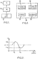
- Figure 2 illustrates variations in the value of the sinusoidal error that affects a measurement from a vibratory gyroscope operating in rate mode.
- the substantially sinusoidal curve is represented in a location representing the vibration position along the x-axis and the measurement value fluctuating as a function of the error considered here along the y-axis.
- the value of the error that is taken into consideration in this case has an average value of zero around the whole circle of the vibration positions.
- a subsequent step is commanded in order to rotate the vibration position to a third position ⁇ 3 , in order to provide a third measurement value val 3 .
- This third vibration position is situated substantially symmetrically with respect to the second position on the other side of the first vibration position.
- Each iteration has a corresponding calibrated scale factor value obtained by calculating the average of the two values calculated for the two vibration positions, which are symmetrical with respect to the first vibration position, corresponding to this iteration. This iteration makes it possible to refine the determination of the calibrated scale factor values.
- the different calibrated scale factor values obtained on each iteration can be added up in order to find their average, by dividing the result of the addition by the number of iterations of these steps.
- Figure 3 illustrates a gyroscopic system according to an embodiment of the present invention.
- This gyroscopic system comprises a first means of measurement 33, i.e. the vibratory gyroscope to be calibrated, and a second means of measurement 34, i.e. the set N-1 of other vibratory gyroscopes. It also comprises:
- the command unit 31 can moreover be capable of applying, over a period of time, a second command capable of commanding a change in vibration position from the second vibration position to the first vibration position; and the determination unit 32 can then moreover be capable of determining a calibrated scale factor value by calculating the average between, on the one hand, the value calculated in relation to the command applied and, on the other hand, a value calculated in relation to the second command based on the period of time during which the second command is applied, the second command, an angular difference between the second and first vibration positions measured according to the first measurement and an angular difference between the second and first vibration positions measured according to the second measurement.
- the command unit 31 is capable of applying, over a period of time, a second command capable of commanding a change in vibration position from the second vibration position to the first vibration position; and of applying, over a period of time, a third command capable of commanding a change in vibration position from the first vibration position to a third vibration position; and the determination unit 32 is moreover capable of determining a calibrated scale factor value by calculating the average between, on the one hand, the value calculated in relation to the initial command and, on the other hand, a value calculated in relation to the third command based on the period of time during which the third command is applied, the third command, an angular difference between the first and third vibration positions measured according to the first measurement and an angular difference between the first and third vibration positions measured according to the second measurement.
- the second and third vibration positions can be situated 90 degrees on either side of the first vibration position respectively.
Landscapes
- Engineering & Computer Science (AREA)
- Physics & Mathematics (AREA)
- General Physics & Mathematics (AREA)
- Radar, Positioning & Navigation (AREA)
- Remote Sensing (AREA)
- Manufacturing & Machinery (AREA)
- Gyroscopes (AREA)
- Navigation (AREA)
Claims (10)
- Verfahren zum Kalibrieren eines in einem Kreiselsystem auf einem beweglichen Träger zu kalibrierenden Kreisels, wobei das Kreiselsystem mindestens vier Vibrationskreisel umfasst, die in der Lage sind, die Vibrationsposition in eine aus einer Mehrzahl von Vibrationspositionen zu verändern;
wobei eine erste Messung durch den zu kalibrierenden Vibrationskreisel bereitgestellt wird und eine zweite Messung durch eine Kombination der jeweiligen Messungen der anderen Vibrationskreisel des Systems bereitgestellt wird, wobei die erste und zweite Messung entlang derselben Messachse durchgeführt werden; wobei das Kalibrierungsverfahren auf der Ebene des zu kalibrierenden Vibrationskreisels die folgenden Schritte umfasst:/1/ Anwenden, auf den zu kalibrierenden Kreisel, über einen Zeitraum, eines Anfangsbefehls zum Ändern der Vibrationsposition von einer ersten Vibrationsposition (θ 1) in eine zweite Vibrationsposition (θ 2); und/2/ Bestimmen eines kalibrierten Skalierungsfaktorwertes des zu kalibrierenden Vibrationskreisels auf der Grundlage eines Wertes, der in Bezug auf Schritt /1/ auf der Grundlage des Zeitraums der Anwendung des Anfangsbefehls, auf der Grundlage des Anfangsbefehls, auf der Grundlage eines entsprechend der ersten Messung gemessenen Winkelunterschieds zwischen der ersten und der zweiten Vibrationsposition und auf der Grundlage eines entsprechend der zweiten Messung während des Zeitraums gemessenen Winkelverschiebungswertes aufgrund der Bewegung des beweglichen Trägers berechnet wird. - Kalibrierungsverfahren nach Anspruch 1, zusätzlich umfassend den folgenden Schritt zwischen Schritt /1/ und Schritt /2/:/1-a/ Anwenden, über einen Zeitraum, eines zweiten Befehls, der in der Lage ist, das Ändern der Vibrationsposition von der zweiten Vibrationsposition in die erste Vibrationsposition zu befehlen; undwobei in Schritt /2/ ein kalibrierter Skalierungsfaktorwert des zu kalibrierenden Vibrationskreisels bestimmt wird, indem der Mittelwert zwischen einerseits dem in Bezug auf Schritt /1/ berechneten Wert und andererseits einem Wert berechnet wird, der in Bezug auf Schritt /1-a/ auf der Grundlage des Zeitraums der Anwendung des zweiten Befehls, auf der Grundlage des zweiten Befehls, auf der Grundlage eines entsprechend der ersten Messung gemessenen Winkelunterschieds zwischen der zweiten und der ersten Vibrationsposition und auf der Grundlage eines entsprechend der zweiten Messung während des Zeitraums gemessenen Winkelverschiebungswertes aufgrund der Bewegung des beweglichen Trägers berechnet wird.
- Kalibrierungsverfahren nach Anspruch 1, zusätzlich umfassend die folgenden Schritte zwischen Schritt /1/ und Schritt /2/:/1-a/ Anwenden, über einen Zeitraum, eines zweiten Befehls, der in der Lage ist, das Ändern der Vibrationsposition von der zweiten Vibrationsposition in die erste Vibrationsposition zu befehlen; und/1-b/ Anwenden, über einen Zeitraum, eines dritten Befehls, der in der Lage ist, das Ändern der Vibrationsposition von der ersten Vibrationsposition in eine dritte Vibrationsposition zu befehlen; undwobei in Schritt /2/ ein kalibrierter Skalierungsfaktorwert des zu kalibrierenden Vibrationskreisels bestimmt wird, indem der Mittelwert zwischen einerseits dem in Bezug auf Schritt /1/ berechneten Wert und andererseits einem Wert berechnet wird, der in Bezug auf Schritt /1-b/ auf der Grundlage des Zeitraums der Anwendung des dritten Befehls, auf der Grundlage des dritten Befehls, auf der Grundlage eines entsprechend der ersten Messung gemessenen Winkelunterschieds zwischen der ersten und der dritten Vibrationsposition und auf der Grundlage eines entsprechend der zweiten Messung während der Zeiträume gemessenen Winkelverschiebungswertes aufgrund der Bewegung des beweglichen Trägers berechnet wird.
- Verfahren zum Kalibrieren eines Kreiselsystems nach Anspruch 3, wobei die zweite und die dritte Vibrationsposition jeweils im 90-Grad-Winkel zu beiden Seiten der ersten Vibrationsposition gelegen sind.
- Verfahren zum Kalibrieren eines Kreiselsystems nach Anspruch 3 oder 4, zusätzlich umfassend den folgenden Schritt:- K-maliges Wiederholen der Schritte /1/, /1-a/ und /1-b/, wobei während jeder Wiederholung die zweite und die dritte Vibrationsposition jeweils von den zweiten und der dritten Vibrationspositionen in den vorher wiederholten Schritten verschieden sind, wobei K eine ganze Zahl ist;wobei ein kalibrierter Skalierungsfaktorwert jeweils für jede Wiederholung bestimmt wird, indem der Mittelwert zwischen den in Bezug auf Schritt /1/ und in Bezug auf Schritt /1-b/ für jede Wiederholung berechneten Werten berechnet wird.
- Verfahren zum Kalibrieren eines Kreiselsystems nach einem der vorangehenden Ansprüche, wobei während der Durchführung der Schritte zum Kalibrieren eines der Vibrationskreisel das Kreiselsystem Kreiselmessungen auf der Grundlage von Messwerten bereitstellt, die von den anderen Vibrationskreiseln des Systems bereitgestellt werden.
- Kreiselsystem (30), umfassend mindestens vier Vibrationskreisel auf einem beweglichen Träger, wobei das Kreiselsystem in der Lage ist, die Vibrationsposition in eine aus einer Mehrzahl von Vibrationspositionen zu verändern;
wobei eine erste Messung (33) durch einen zu kalibrierenden Vibrationskreisel bereitgestellt wird, der zu den mindestens vier Vibrationskreiseln des Kreiselsystems gehört, und eine zweite Messung durch eine Kombination der jeweiligen Messungen der anderen Vibrationskreisel des Systems bereitgestellt wird, wobei die erste und zweite Messung entlang derselben Messachse durchgeführt werden;
das Kreiselsystem umfassend:- eine Befehlseinheit (31) zum Anwenden, über einen Zeitraum, eines Anfangsbefehls zum Ändern der Vibrationsposition von einer ersten Vibrationsposition (θ 1) in eine zweite Vibrationsposition (θ 2); und- eine Bestimmungseinheit (32), die in der Lage ist, einen kalibrierten Skalierungsfaktorwert des zu kalibrierenden Vibrationskreisels auf der Grundlage eines Wertes zu bestimmen, der in Bezug auf den Anfangsbefehl auf der Grundlage des Zeitraums der Anwendung des Befehls, auf der Grundlage des Befehls, auf der Grundlage eines entsprechend der ersten Messung gemessenen Winkelunterschieds zwischen der ersten und der zweiten Vibrationsposition und auf der Grundlage eines entsprechend der zweiten Messung während des Zeitraums gemessenen Winkelverschiebungswertes aufgrund der Bewegung des beweglichen Trägers berechnet wird. - Kreiselsystem nach Anspruch 7,
wobei die Befehlseinheit (31)
außerdem in der Lage ist, über einen Zeitraum einen zweiten Befehl anzuwenden, der in der Lage ist, das Ändern der Vibrationsposition von der zweiten Vibrationsposition in die erste Vibrationsposition zu befehlen; und
wobei die Bestimmungseinheit (32) außerdem in der Lage ist, einen kalibrierten Skalierungsfaktorwert zu bestimmen, indem der Mittelwert zwischen einerseits dem in Bezug auf den Anfangsbefehl berechneten Wert und andererseits einem Wert berechnet wird, der in Bezug auf den zweiten Befehl auf der Grundlage des Zeitraums der Anwendung des zweiten Befehls, auf der Grundlage des zweiten Befehls, auf der Grundlage eines entsprechend der ersten Messung gemessenen Winkelunterschieds zwischen der zweiten und der ersten Vibrationsposition und auf der Grundlage eines entsprechend der zweiten Messung während des Zeitraums gemessenen Winkelverschiebungswertes aufgrund der Bewegung des beweglichen Trägers berechnet wird. - Kreiselsystem nach Anspruch 7,
wobei die Befehlseinheit (31) in der Lage ist, über einen Zeitraum einen zweiten Befehl anzuwenden, der in der Lage ist, das Ändern der Vibrationsposition von der zweiten Vibrationsposition in die erste Vibrationsposition zu befehlen; und über einen Zeitraum einen dritten Befehl anzuwenden, der in der Lage ist, das Ändern der Vibrationsposition von der ersten Vibrationsposition in eine dritte Vibrationsposition zu befehlen; und
wobei die Bestimmungseinheit (32) außerdem in der Lage ist, einen kalibrierten Skalierungsfaktorwert zu bestimmen, indem der Mittelwert zwischen einerseits dem in Bezug auf den Anfangsbefehl berechneten Wert und andererseits einem Wert berechnet wird, der in Bezug auf den dritten Befehl auf der Grundlage des Zeitraums der Anwendung des dritten Befehls, auf der Grundlage des dritten Befehls, auf der Grundlage eines entsprechend der ersten Messung gemessenen Winkelunterschieds zwischen der ersten und der dritten Vibrationsposition und auf der Grundlage eines entsprechend der zweiten Messung während der Zeiträume gemessenen Winkelverschiebungswertes aufgrund der Bewegung des beweglichen Trägers berechnet wird. - Kreiselsystem nach einem der Ansprüche 7 bis 9,
wobei die zweite und die dritte Vibrationsposition jeweils im 90-Grad-Winkel zu beiden Seiten der ersten Vibrationsposition gelegen sind.
Applications Claiming Priority (2)
| Application Number | Priority Date | Filing Date | Title |
|---|---|---|---|
| FR0858145A FR2939192B1 (fr) | 2008-11-28 | 2008-11-28 | Calibrage de systemes gyroscopiques a gyroscopes vibrants |
| PCT/EP2009/066001 WO2010060994A1 (en) | 2008-11-28 | 2009-11-27 | Calibration of gyroscopic systems with vibratory gyroscopes |
Publications (2)
| Publication Number | Publication Date |
|---|---|
| EP2359092A1 EP2359092A1 (de) | 2011-08-24 |
| EP2359092B1 true EP2359092B1 (de) | 2018-10-31 |
Family
ID=41698360
Family Applications (1)
| Application Number | Title | Priority Date | Filing Date |
|---|---|---|---|
| EP09795362.4A Active EP2359092B1 (de) | 2008-11-28 | 2009-11-27 | Kalibration von kreiselsystemen mit vibrationskreiseln |
Country Status (6)
| Country | Link |
|---|---|
| US (1) | US8800349B2 (de) |
| EP (1) | EP2359092B1 (de) |
| CN (1) | CN102224395B (de) |
| FR (1) | FR2939192B1 (de) |
| RU (1) | RU2509981C2 (de) |
| WO (1) | WO2010060994A1 (de) |
Families Citing this family (10)
| Publication number | Priority date | Publication date | Assignee | Title |
|---|---|---|---|---|
| CN102426456B (zh) * | 2011-09-01 | 2013-09-11 | 中国航空工业第六一八研究所 | 一种惯性系统的托架标定和补偿方法 |
| CN102607590B (zh) * | 2012-02-24 | 2014-05-07 | 北京航空航天大学 | 一种基于光纤陀螺监测的挠性陀螺过载项抗干扰测试装置 |
| FR2998663B1 (fr) * | 2012-11-28 | 2014-11-21 | Sagem Defense Securite | Procede de calibration d'une centrale inertielle a plage de retournement mecanique limitee |
| KR102305093B1 (ko) | 2015-02-26 | 2021-09-28 | 삼성전자주식회사 | 전자 장치 및 전자 장치의 자이로 센서 칼리브레이션 방법 |
| FR3036788B1 (fr) | 2015-05-26 | 2017-06-09 | Sagem Defense Securite | Procede de commande de precession d'un gyroscope vibrant |
| FR3038048B1 (fr) * | 2015-06-23 | 2017-07-07 | Sagem Defense Securite | Systeme inertiel de mesure pour aeronef |
| US10466067B2 (en) * | 2017-01-19 | 2019-11-05 | The Boeing Company | System and method for gyro rate computation for a Coriolis Vibrating Gyroscope |
| RU2678959C1 (ru) * | 2018-02-14 | 2019-02-04 | Акционерное общество "Концерн "Центральный научно-исследовательский институт "Электроприбор" | Способ калибровки погрешностей электростатических гироскопов бескарданной инерциальной системы ориентации в условиях орбитального космического аппарата |
| CN111314607B (zh) * | 2020-02-21 | 2021-07-13 | 昆山丘钛微电子科技有限公司 | 一种光学防抖的标定方法、装置、电子设备及介质 |
| FR3120121B1 (fr) * | 2021-02-19 | 2023-04-28 | Thales Sa | Procédé de correction de la mesure d'un capteur inertiel angulaire vibrant |
Citations (1)
| Publication number | Priority date | Publication date | Assignee | Title |
|---|---|---|---|---|
| WO2009083519A1 (fr) * | 2007-12-21 | 2009-07-09 | Sagem Defense Securite | Procede de mesure par systeme gyroscopique |
Family Cites Families (11)
| Publication number | Priority date | Publication date | Assignee | Title |
|---|---|---|---|---|
| US5712427A (en) * | 1995-08-29 | 1998-01-27 | Litton Systems Inc. | Vibratory rotation sensor with scanning-tunneling-transducer readout |
| FR2755227B1 (fr) | 1996-10-31 | 1998-12-31 | Sagem | Appareil de mesure de rotation a resonateur mecanique vibrant |
| RU2156959C1 (ru) * | 1999-06-01 | 2000-09-27 | Лебеденко Олег Станиславович | Способ калибровки гироскопических измерителей угловой скорости |
| US6598455B1 (en) * | 1999-06-30 | 2003-07-29 | California Institute Of Technology | Non-inertial calibration of vibratory gyroscopes |
| RU2249793C2 (ru) * | 2002-08-06 | 2005-04-10 | Открытое акционерное общество Пермская научно-производственная приборостроительная компания | Способ калибровки акселерометров |
| GB0227084D0 (en) * | 2002-11-20 | 2002-12-24 | Bae Systems Plc | Method and apparatus for measuring scalefactor variation in a vibrating structure gyroscope |
| US7464590B1 (en) * | 2004-03-12 | 2008-12-16 | Thomson Licensing | Digitally programmable bandwidth for vibratory rate gyroscope |
| FR2910615B1 (fr) * | 2006-12-20 | 2009-02-06 | Sagem Defense Securite | Procede de calibrage du facteur d'echelle d'un gyrometre vibrant axisymetrique |
| US7739896B2 (en) * | 2007-03-15 | 2010-06-22 | Northrop Grumman Guidance And Electronics Company, Inc. | Self-calibration of scale factor for dual resonator class II coriolis vibratory gyros |
| FR2920224B1 (fr) * | 2007-08-23 | 2009-10-02 | Sagem Defense Securite | Procede de determination d'une vitesse de rotation d'un capteur vibrant axisymetrique, et dispositif inertiel mettant en oeuvre le procede |
| CN100559123C (zh) * | 2007-10-25 | 2009-11-11 | 北京航空航天大学 | 一种mems陀螺仪的差分测量方法 |
-
2008
- 2008-11-28 FR FR0858145A patent/FR2939192B1/fr active Active
-
2009
- 2009-11-27 CN CN200980148049.9A patent/CN102224395B/zh active Active
- 2009-11-27 US US13/125,442 patent/US8800349B2/en active Active
- 2009-11-27 WO PCT/EP2009/066001 patent/WO2010060994A1/en active Application Filing
- 2009-11-27 RU RU2011126366/28A patent/RU2509981C2/ru active
- 2009-11-27 EP EP09795362.4A patent/EP2359092B1/de active Active
Patent Citations (1)
| Publication number | Priority date | Publication date | Assignee | Title |
|---|---|---|---|---|
| WO2009083519A1 (fr) * | 2007-12-21 | 2009-07-09 | Sagem Defense Securite | Procede de mesure par systeme gyroscopique |
Also Published As
| Publication number | Publication date |
|---|---|
| EP2359092A1 (de) | 2011-08-24 |
| FR2939192B1 (fr) | 2010-12-10 |
| RU2011126366A (ru) | 2013-01-10 |
| WO2010060994A1 (en) | 2010-06-03 |
| FR2939192A1 (fr) | 2010-06-04 |
| CN102224395A (zh) | 2011-10-19 |
| RU2509981C2 (ru) | 2014-03-20 |
| US8800349B2 (en) | 2014-08-12 |
| US20110259078A1 (en) | 2011-10-27 |
| CN102224395B (zh) | 2014-05-14 |
Similar Documents
| Publication | Publication Date | Title |
|---|---|---|
| EP2359092B1 (de) | Kalibration von kreiselsystemen mit vibrationskreiseln | |
| US7739896B2 (en) | Self-calibration of scale factor for dual resonator class II coriolis vibratory gyros | |
| US7997134B2 (en) | Measurement by gyroscopic system | |
| EP2356404B1 (de) | Kalibrierung eines vibrationskreisels | |
| EP2472225B1 (de) | Verfahren und System zur anfänglichen Quaternion- und Lageschätzung | |
| EP1582840B1 (de) | Fehlerkorrektur für ein Inertialnavigationssystem | |
| EP1941236B1 (de) | Systeme und verfahren zur verringerung vibrationsbedingter fehler in trägheitssensoren | |
| US8768621B2 (en) | Signal processing module, navigation device with the signal processing module, vehicle provided with a navigation device and method of providing navigation data | |
| RU2390728C1 (ru) | Способ настройки инерциальной навигационной системы с осесимметричным вибрационным датчиком и соответствующая инерциальная навигационная система | |
| US20150204674A1 (en) | Inertial Navigation System and Method | |
| JP4929445B2 (ja) | 力に依存するジャイロスコープの感度を測定する方法 | |
| CN106767767A (zh) | 一种微纳多模星敏感器系统及其数据融合方法 | |
| US8342024B2 (en) | Gyroscopic measurement by a vibratory gyroscope | |
| US8725415B2 (en) | Method and device for long-duration navigation | |
| CN115790653A (zh) | 一种用于旋转式惯导的自对准方法及装置 | |
| CN112697143B (zh) | 高精度载体动态姿态测量方法及系统 | |
| US20220250773A1 (en) | Device and method for determining the attitude of a satellite equipped with gyroscopic actuators, and satellite carrying such a device | |
| RU2589508C2 (ru) | Способ автоматического управления гиродатчиком угловой скорости тангажа, установленным на летательном аппарате | |
| US9671248B2 (en) | Method for calibrating an inertial navigation system with a limited mechanical turning range | |
| US8612068B2 (en) | Apparatus and method for propagating the attitude of a vehicle | |
| US20080121055A1 (en) | System and method for reducing attitude errors for exoatmospheric devices |
Legal Events
| Date | Code | Title | Description |
|---|---|---|---|
| PUAI | Public reference made under article 153(3) epc to a published international application that has entered the european phase |
Free format text: ORIGINAL CODE: 0009012 |
|
| 17P | Request for examination filed |
Effective date: 20110525 |
|
| AK | Designated contracting states |
Kind code of ref document: A1 Designated state(s): AT BE BG CH CY CZ DE DK EE ES FI FR GB GR HR HU IE IS IT LI LT LU LV MC MK MT NL NO PL PT RO SE SI SK SM TR |
|
| DAX | Request for extension of the european patent (deleted) | ||
| RAP1 | Party data changed (applicant data changed or rights of an application transferred) |
Owner name: SAGEM DEFENSE SECURITE |
|
| RAP1 | Party data changed (applicant data changed or rights of an application transferred) |
Owner name: SAFRAN ELECTRONICS & DEFENSE |
|
| 17Q | First examination report despatched |
Effective date: 20171025 |
|
| GRAP | Despatch of communication of intention to grant a patent |
Free format text: ORIGINAL CODE: EPIDOSNIGR1 |
|
| INTG | Intention to grant announced |
Effective date: 20180524 |
|
| GRAS | Grant fee paid |
Free format text: ORIGINAL CODE: EPIDOSNIGR3 |
|
| GRAA | (expected) grant |
Free format text: ORIGINAL CODE: 0009210 |
|
| AK | Designated contracting states |
Kind code of ref document: B1 Designated state(s): AT BE BG CH CY CZ DE DK EE ES FI FR GB GR HR HU IE IS IT LI LT LU LV MC MK MT NL NO PL PT RO SE SI SK SM TR |
|
| REG | Reference to a national code |
Ref country code: CH Ref legal event code: EP Ref country code: GB Ref legal event code: FG4D |
|
| REG | Reference to a national code |
Ref country code: AT Ref legal event code: REF Ref document number: 1059924 Country of ref document: AT Kind code of ref document: T Effective date: 20181115 |
|
| REG | Reference to a national code |
Ref country code: IE Ref legal event code: FG4D |
|
| REG | Reference to a national code |
Ref country code: DE Ref legal event code: R096 Ref document number: 602009055394 Country of ref document: DE |
|
| REG | Reference to a national code |
Ref country code: NO Ref legal event code: T2 Effective date: 20181031 |
|
| REG | Reference to a national code |
Ref country code: NL Ref legal event code: MP Effective date: 20181031 |
|
| REG | Reference to a national code |
Ref country code: LT Ref legal event code: MG4D |
|
| REG | Reference to a national code |
Ref country code: AT Ref legal event code: MK05 Ref document number: 1059924 Country of ref document: AT Kind code of ref document: T Effective date: 20181031 |
|
| PG25 | Lapsed in a contracting state [announced via postgrant information from national office to epo] |
Ref country code: AT Free format text: LAPSE BECAUSE OF FAILURE TO SUBMIT A TRANSLATION OF THE DESCRIPTION OR TO PAY THE FEE WITHIN THE PRESCRIBED TIME-LIMIT Effective date: 20181031 Ref country code: LT Free format text: LAPSE BECAUSE OF FAILURE TO SUBMIT A TRANSLATION OF THE DESCRIPTION OR TO PAY THE FEE WITHIN THE PRESCRIBED TIME-LIMIT Effective date: 20181031 Ref country code: LV Free format text: LAPSE BECAUSE OF FAILURE TO SUBMIT A TRANSLATION OF THE DESCRIPTION OR TO PAY THE FEE WITHIN THE PRESCRIBED TIME-LIMIT Effective date: 20181031 Ref country code: BG Free format text: LAPSE BECAUSE OF FAILURE TO SUBMIT A TRANSLATION OF THE DESCRIPTION OR TO PAY THE FEE WITHIN THE PRESCRIBED TIME-LIMIT Effective date: 20190131 Ref country code: ES Free format text: LAPSE BECAUSE OF FAILURE TO SUBMIT A TRANSLATION OF THE DESCRIPTION OR TO PAY THE FEE WITHIN THE PRESCRIBED TIME-LIMIT Effective date: 20181031 Ref country code: HR Free format text: LAPSE BECAUSE OF FAILURE TO SUBMIT A TRANSLATION OF THE DESCRIPTION OR TO PAY THE FEE WITHIN THE PRESCRIBED TIME-LIMIT Effective date: 20181031 Ref country code: PL Free format text: LAPSE BECAUSE OF FAILURE TO SUBMIT A TRANSLATION OF THE DESCRIPTION OR TO PAY THE FEE WITHIN THE PRESCRIBED TIME-LIMIT Effective date: 20181031 Ref country code: FI Free format text: LAPSE BECAUSE OF FAILURE TO SUBMIT A TRANSLATION OF THE DESCRIPTION OR TO PAY THE FEE WITHIN THE PRESCRIBED TIME-LIMIT Effective date: 20181031 Ref country code: IS Free format text: LAPSE BECAUSE OF FAILURE TO SUBMIT A TRANSLATION OF THE DESCRIPTION OR TO PAY THE FEE WITHIN THE PRESCRIBED TIME-LIMIT Effective date: 20190228 |
|
| PG25 | Lapsed in a contracting state [announced via postgrant information from national office to epo] |
Ref country code: PT Free format text: LAPSE BECAUSE OF FAILURE TO SUBMIT A TRANSLATION OF THE DESCRIPTION OR TO PAY THE FEE WITHIN THE PRESCRIBED TIME-LIMIT Effective date: 20190301 Ref country code: GR Free format text: LAPSE BECAUSE OF FAILURE TO SUBMIT A TRANSLATION OF THE DESCRIPTION OR TO PAY THE FEE WITHIN THE PRESCRIBED TIME-LIMIT Effective date: 20190201 Ref country code: SE Free format text: LAPSE BECAUSE OF FAILURE TO SUBMIT A TRANSLATION OF THE DESCRIPTION OR TO PAY THE FEE WITHIN THE PRESCRIBED TIME-LIMIT Effective date: 20181031 Ref country code: NL Free format text: LAPSE BECAUSE OF FAILURE TO SUBMIT A TRANSLATION OF THE DESCRIPTION OR TO PAY THE FEE WITHIN THE PRESCRIBED TIME-LIMIT Effective date: 20181031 |
|
| REG | Reference to a national code |
Ref country code: CH Ref legal event code: PL |
|
| PG25 | Lapsed in a contracting state [announced via postgrant information from national office to epo] |
Ref country code: DK Free format text: LAPSE BECAUSE OF FAILURE TO SUBMIT A TRANSLATION OF THE DESCRIPTION OR TO PAY THE FEE WITHIN THE PRESCRIBED TIME-LIMIT Effective date: 20181031 Ref country code: CZ Free format text: LAPSE BECAUSE OF FAILURE TO SUBMIT A TRANSLATION OF THE DESCRIPTION OR TO PAY THE FEE WITHIN THE PRESCRIBED TIME-LIMIT Effective date: 20181031 Ref country code: LU Free format text: LAPSE BECAUSE OF NON-PAYMENT OF DUE FEES Effective date: 20181127 |
|
| REG | Reference to a national code |
Ref country code: DE Ref legal event code: R097 Ref document number: 602009055394 Country of ref document: DE |
|
| REG | Reference to a national code |
Ref country code: BE Ref legal event code: MM Effective date: 20181130 |
|
| PG25 | Lapsed in a contracting state [announced via postgrant information from national office to epo] |
Ref country code: RO Free format text: LAPSE BECAUSE OF FAILURE TO SUBMIT A TRANSLATION OF THE DESCRIPTION OR TO PAY THE FEE WITHIN THE PRESCRIBED TIME-LIMIT Effective date: 20181031 Ref country code: SK Free format text: LAPSE BECAUSE OF FAILURE TO SUBMIT A TRANSLATION OF THE DESCRIPTION OR TO PAY THE FEE WITHIN THE PRESCRIBED TIME-LIMIT Effective date: 20181031 Ref country code: CH Free format text: LAPSE BECAUSE OF NON-PAYMENT OF DUE FEES Effective date: 20181130 Ref country code: MC Free format text: LAPSE BECAUSE OF FAILURE TO SUBMIT A TRANSLATION OF THE DESCRIPTION OR TO PAY THE FEE WITHIN THE PRESCRIBED TIME-LIMIT Effective date: 20181031 Ref country code: LI Free format text: LAPSE BECAUSE OF NON-PAYMENT OF DUE FEES Effective date: 20181130 Ref country code: SM Free format text: LAPSE BECAUSE OF FAILURE TO SUBMIT A TRANSLATION OF THE DESCRIPTION OR TO PAY THE FEE WITHIN THE PRESCRIBED TIME-LIMIT Effective date: 20181031 Ref country code: EE Free format text: LAPSE BECAUSE OF FAILURE TO SUBMIT A TRANSLATION OF THE DESCRIPTION OR TO PAY THE FEE WITHIN THE PRESCRIBED TIME-LIMIT Effective date: 20181031 |
|
| PLBE | No opposition filed within time limit |
Free format text: ORIGINAL CODE: 0009261 |
|
| STAA | Information on the status of an ep patent application or granted ep patent |
Free format text: STATUS: NO OPPOSITION FILED WITHIN TIME LIMIT |
|
| 26N | No opposition filed |
Effective date: 20190801 |
|
| PG25 | Lapsed in a contracting state [announced via postgrant information from national office to epo] |
Ref country code: SI Free format text: LAPSE BECAUSE OF FAILURE TO SUBMIT A TRANSLATION OF THE DESCRIPTION OR TO PAY THE FEE WITHIN THE PRESCRIBED TIME-LIMIT Effective date: 20181031 |
|
| PG25 | Lapsed in a contracting state [announced via postgrant information from national office to epo] |
Ref country code: BE Free format text: LAPSE BECAUSE OF NON-PAYMENT OF DUE FEES Effective date: 20181130 |
|
| PG25 | Lapsed in a contracting state [announced via postgrant information from national office to epo] |
Ref country code: MT Free format text: LAPSE BECAUSE OF NON-PAYMENT OF DUE FEES Effective date: 20181127 |
|
| PG25 | Lapsed in a contracting state [announced via postgrant information from national office to epo] |
Ref country code: TR Free format text: LAPSE BECAUSE OF FAILURE TO SUBMIT A TRANSLATION OF THE DESCRIPTION OR TO PAY THE FEE WITHIN THE PRESCRIBED TIME-LIMIT Effective date: 20181031 |
|
| PG25 | Lapsed in a contracting state [announced via postgrant information from national office to epo] |
Ref country code: HU Free format text: LAPSE BECAUSE OF FAILURE TO SUBMIT A TRANSLATION OF THE DESCRIPTION OR TO PAY THE FEE WITHIN THE PRESCRIBED TIME-LIMIT; INVALID AB INITIO Effective date: 20091127 Ref country code: CY Free format text: LAPSE BECAUSE OF FAILURE TO SUBMIT A TRANSLATION OF THE DESCRIPTION OR TO PAY THE FEE WITHIN THE PRESCRIBED TIME-LIMIT Effective date: 20181031 Ref country code: MK Free format text: LAPSE BECAUSE OF NON-PAYMENT OF DUE FEES Effective date: 20181031 |
|
| PGFP | Annual fee paid to national office [announced via postgrant information from national office to epo] |
Ref country code: GB Payment date: 20231019 Year of fee payment: 15 |
|
| PGFP | Annual fee paid to national office [announced via postgrant information from national office to epo] |
Ref country code: NO Payment date: 20231023 Year of fee payment: 15 Ref country code: IT Payment date: 20231019 Year of fee payment: 15 Ref country code: IE Payment date: 20231023 Year of fee payment: 15 Ref country code: FR Payment date: 20231020 Year of fee payment: 15 Ref country code: DE Payment date: 20231019 Year of fee payment: 15 |