EP2358552B1 - Arrangement d'un dispositif de charge dans un vehicule et procédé de production d'énergie thermique - Google Patents
Arrangement d'un dispositif de charge dans un vehicule et procédé de production d'énergie thermique Download PDFInfo
- Publication number
- EP2358552B1 EP2358552B1 EP09795680.9A EP09795680A EP2358552B1 EP 2358552 B1 EP2358552 B1 EP 2358552B1 EP 09795680 A EP09795680 A EP 09795680A EP 2358552 B1 EP2358552 B1 EP 2358552B1
- Authority
- EP
- European Patent Office
- Prior art keywords
- burner
- evaporator
- fuel
- housing
- heat
- Prior art date
- Legal status (The legal status is an assumption and is not a legal conclusion. Google has not performed a legal analysis and makes no representation as to the accuracy of the status listed.)
- Active
Links
Images


Classifications
-
- F—MECHANICAL ENGINEERING; LIGHTING; HEATING; WEAPONS; BLASTING
- F23—COMBUSTION APPARATUS; COMBUSTION PROCESSES
- F23D—BURNERS
- F23D11/00—Burners using a direct spraying action of liquid droplets or vaporised liquid into the combustion space
- F23D11/005—Burners using a direct spraying action of liquid droplets or vaporised liquid into the combustion space with combinations of different spraying or vaporising means
-
- F—MECHANICAL ENGINEERING; LIGHTING; HEATING; WEAPONS; BLASTING
- F23—COMBUSTION APPARATUS; COMBUSTION PROCESSES
- F23D—BURNERS
- F23D11/00—Burners using a direct spraying action of liquid droplets or vaporised liquid into the combustion space
- F23D11/36—Details
- F23D11/44—Preheating devices; Vaporising devices
- F23D11/441—Vaporising devices incorporated with burners
- F23D11/448—Vaporising devices incorporated with burners heated by electrical means
-
- H—ELECTRICITY
- H01—ELECTRIC ELEMENTS
- H01M—PROCESSES OR MEANS, e.g. BATTERIES, FOR THE DIRECT CONVERSION OF CHEMICAL ENERGY INTO ELECTRICAL ENERGY
- H01M10/00—Secondary cells; Manufacture thereof
- H01M10/42—Methods or arrangements for servicing or maintenance of secondary cells or secondary half-cells
- H01M10/46—Accumulators structurally combined with charging apparatus
-
- Y—GENERAL TAGGING OF NEW TECHNOLOGICAL DEVELOPMENTS; GENERAL TAGGING OF CROSS-SECTIONAL TECHNOLOGIES SPANNING OVER SEVERAL SECTIONS OF THE IPC; TECHNICAL SUBJECTS COVERED BY FORMER USPC CROSS-REFERENCE ART COLLECTIONS [XRACs] AND DIGESTS
- Y02—TECHNOLOGIES OR APPLICATIONS FOR MITIGATION OR ADAPTATION AGAINST CLIMATE CHANGE
- Y02E—REDUCTION OF GREENHOUSE GAS [GHG] EMISSIONS, RELATED TO ENERGY GENERATION, TRANSMISSION OR DISTRIBUTION
- Y02E60/00—Enabling technologies; Technologies with a potential or indirect contribution to GHG emissions mitigation
- Y02E60/10—Energy storage using batteries
Definitions
- the invention relates to an arrangement of a charging device in a vehicle, the charging device for charging an energy storage of the vehicle and a power generating device, a charger and other components, wherein the power generating device by a heat source, which at least one connected to a supply line for a fuel burner and a thermocouple is formed, and one side of the thermocouple is connected to the heat source and the other side of the thermocouple to a rear wall of the housing, wherein the power generating device, the charger and the other components are arranged in a common housing.
- the invention further relates to a method for generating a heat energy in a heat source of a power generating device of a charging device for charging an energy storage device of a vehicle, wherein the heat energy is generated by a burner of the heat source, and the heat energy is at least partially converted into electricity by a thermocouple of the power generating device ,
- the DE 38 07 633 A1 describes a rechargeable battery that can be charged independently of the electrical grid by using a power generator heat energy is converted directly into electrical energy.
- the DE 195 29 564 A1 relates to a motor vehicle with a built-in auxiliary heating, wherein utilizing the Seebeck effect electrical energy to supply the necessary components for the auxiliary heating components to relieve the car battery accordingly.
- thermocouple generates an electrical voltage or electrical energy when it is connected to a consumer and thus an electric current flows.
- a prerequisite for the occurrence of the thermoelectric voltage is a certain temperature difference between one side and the opposite side of the thermocouple.
- one side of the thermocouple is heated by means of the burner, which burns the fuel from the tank, whereas the other side of the thermocouple has ambient temperature, so that the temperature difference necessary for the thermoelectric voltage is ensured.
- lithium-ion and lithium-polymer batteries with a maximum capacity of 0.5 ampere-hours (Ah) can be charged with this method.
- a so-called screw burner no stable combustion possible, so that the required for effective power generation constant temperature difference can not be achieved.
- the DE 10 2004 020 507 A1 describes an evaporator arrangement for a fuel cell system, wherein several areas are arranged in the burner housing.
- the EP 1 696 175 A1 describes a combustion chamber housing for an evaporator burner for a vehicle heater, wherein the burner is arranged in the lowermost region of the burner housing.
- the EP 1 332 897 A2 discloses a heat exchanger assembly for a heater in particular a heater for a vehicle of the subject type.
- the object of the present invention is to provide an above arrangement of a charging device in a vehicle for charging an energy storage and a method for generating heat energy in a heat source of a power generating device of a charging device, by which a constant stable combustion and the self-preservation of an evaporation process are possible , Disadvantages of the prior art should be avoided or at least reduced.
- a charging device in a vehicle in which an evaporator for the fuel supplied is arranged in the lowermost portion of a burner housing of the burner, and the rear wall of the housing is attached to a dissipating the heat engine block of the vehicle , It is advantageous here and in the features according to claims 2 to 5, that a reliable protection against dirt is ensured, since everything is integrated in the device. Likewise, a simple assembly is given to the element of the vehicle via the rear wall of the charging device, wherein the rear wall is designed simultaneously as a heat sink. Thus, an optimal heat transfer between the element of the vehicle and the rear wall is ensured.
- the rear wall and the element of the vehicle form a common element for dissipating the heat, thereby ensuring optimum heat dissipation and constant power generation.
- a substantially vertical arrangement of the burner is advantageous because the structure of the burner is optimized for this position and thus optimal use is given.
- several areas are arranged one above the other in the burner housing of the burner, in the lowermost region of the burner housing the evaporator, followed by a mixing region, a combustion chamber and an exhaust space, and with an ignition device arranged in a region, wherein in the combustion chamber, a ceramic filler is arranged above a spacer ring, to ensure that the fuel mixture does not flow beyond the ceramic filler and the combustion process takes place exclusively in the combustion chamber, wherein the spacer ring forms a space in the interior and the ignition device is arranged in this space or in the exhaust gas space.
- the mixing chamber is designed to produce a fuel mixture, and the mixing chamber is connected to the combustion chamber via a flow opening and a screen, the outflow speed of the fuel vapor is slowed down and this is swirled, so that a uniform distribution takes place. This stabilizes combustion extremely effectively.
- combustion chamber is connected to the exhaust space arranged in the upper part of the burner housing, and the exhaust space is connected via an outlet opening with a heat exchanger for passing at least a portion of a thermal energy formed during combustion in the combustion chamber to a thermocouple, no backflow of the exhaust gases in the Combustion chamber possible. This ensures a stable combustion process. Similarly, the heat generated by the burner is passed through the heat exchanger to the thermocouple.
- the measures according to claims 8 and 9 is advantageous in that an enlargement of the surface is achieved by the filler. As a result, the supplied fuel is distributed on this surface and is thus evenly and completely evaporated, as this is the effect of a so-called Droplet having. This means that the resulting in the supply of the fuel splash remain in the filler and in turn evaporate. Likewise, the controlled fuel supply results in an optimal fuel-air mixture for an optimal flame without soot. Accordingly, the temperature of the evaporator is of importance, which results inter alia from the return of the heat energy. This can also be ensured with a heating device, in particular in a starting phase.
- a flap made of bimetal can be arranged in the air supply pipe.
- the cleaning area can be formed, for example, by at least one filter. In particular, deposits in the channel of the nozzle are effectively prevented.
- a heating device connected to the evaporator of the burner is provided and adapted the outer shape of the heater to the outer shape of the burner housing. It is advantageous here and by the features of claim 10, that the evaporator is brought at least in the start-up phase to the temperature required for a stable evaporation process, so that a stable combustion process is also possible accordingly. Likewise, an active control during the evaporation process is possible in an advantageous manner.
- An advantage is also an arranged between the evaporator and the bobbin insulation layer, whereby the heater is protected from the high temperatures of the evaporator and the windings are not melted.
- the heating device described above is formed at least with a part of a burner described above for use in an apparatus described above for charging an energy store.
- the nozzle for the burner is formed as a disc and adapted to the shape of the burner housing and has at least one channel, wherein the height of the disc and the shape of the channel is adapted to the performance of the burner. It is advantageous in this case and according to claim 11 that due to the very short channel, this essentially can no longer grow, so that a continuous concentration of the fuel vapor and the pressure build-up in the evaporator is ensured.
- the object is also achieved by an above-mentioned method for generating a heat energy in a heat source in a power generating device of a charging device for charging an energy storage device of a vehicle, wherein in a arranged in the lowermost portion of a burner housing of the burner evaporator of the burner from a fuel supplied a fuel vapor is generated, the fuel vapor is mixed in a mixing region of the burner by admixing air to a fuel mixture and this is burned in a combustion chamber of the burner to generate the heat energy, wherein the heat energy is supplied via an exhaust gas chamber on one side of the thermocouple and the other side of the thermocouple is attached to an engine block of the vehicle.
- the method of generating heat energy described above is preferably performed with a charging device, burner, heater and nozzle as described above.
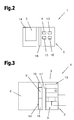
- the charging device 1 includes a power generating device 3 and a charger 4.
- the power generating device 3 and the charger 4 are preferably disposed in a housing 5 which is attached to an element of the vehicle 7 (for example, passenger car, truck, motorcycle, ship, etc.) Dissipation of the heat is formed, mounted.
- the element for dissipating the heat for example, a metallic part of the vehicle 7, such as an engine block 6. Accordingly, therefore, the engine block 6 is formed as an element for dissipating the heat.
- the power generating device 3 consists of at least a burner 8, a thermocouple 9 and at least one element for dissipating the heat, as described and shown in detail below.
- the burner 8 is connected to a supply line 10 for a fuel of a tank 11 of the vehicle 7, which is branched off in the engine compartment of the vehicle 7 from a supply line 12 of the fuel for the engine.
- the charging device 1 is also connected to a control device 13, as will be shown below.
- the energy storage 2 can be charged by the required power or the required power is generated by the thermocouple 9, provided that a corresponding temperature difference between the two sides of the thermocouple 9 is given.
- thermocouple 9 between a so-called “hot-side” and an opposite so-called “cold side” is attached. Accordingly, the "hot side” of the thermocouple 9 on the burner 8 and the "cold side” of the thermocouple 9 on the engine block 6, which serves as an element for dissipating the heat, attached.
- the energy storage 2 of a parked, not in operation vehicle 7 can be loaded to maintain the charging level of the energy storage device 2.
- the original charge level or state of charge of the energy storage device 2 can thus be maintained for a long time since a self-discharge of the energy storage device 2 due to the removal of the stored energy by consumers can be counteracted.
- the functionality of the energy store 2 is maintained, in particular by a gentle charge, so that, for example, the properties of a starter battery of the vehicle 7 used as an energy store 2 are not impaired.
- FIGS. 2 and 3 a charging device 1 and its components are shown. From this it can be seen in particular that the housing 5 is formed substantially split, wherein in one part the power generating device 3 and in the other part the charger 4 and other components for the charging device 1, such as the control device 13, a fuel filter 15 and a fuel pump 16, are arranged.
- the division of the housing 5 can be realized by an insulation 18, which will be discussed in detail later.
- the power generating device 3 includes a heat source, consisting of the burner 8 and preferably a heat exchanger 17, and the thermocouple 9.
- the rear wall 14 of the housing 5 forms the "cold side” and the heat exchanger 17, the "hot side” of the thermocouple 9, which is preferably connected directly to these components. Accordingly, the "hot side” is heated with a corresponding heat energy through the heat exchanger 17, wherein the non-recoverable from the thermocouple 9 thermal energy is dissipated via the rear wall 14 and subsequently via the serving as an element for dissipating the heat engine block 6.
- the rear wall 14 is designed as a heat sink and consequently already as an element for dissipating the heat, so that the charging device 1 can operate independently of the engine block 6.
- the rear wall 14 is mounted on the engine block 6, so that a common element for dissipating the heat is formed by the rear wall 14 and the engine block 6 and the possible operating time of the charging device 1 is extended.
- the heat energy required for power generation via the thermocouple 9 is generated via the coupled to the heat exchanger 17 burner 8, which burns the fuel.
- This heat energy formed in the burner 8 is composed of an exhaust heat, a heat radiation and a heat transfer by a mechanical contact.
- the heat energy is determined by the energy throughput or turnover, which depends essentially on the amount of fuel supplied.
- the exhaust heat is used in such a way that the resulting in the combustion of the fuel in the burner 8 hot exhaust gases are passed into the upper part of the heat exchanger 17 and are passed in the lower part of the housing 5 accordingly. As a result, therefore, the heat exchanger 17 and subsequently the "hot side" of the thermocouple 9 is heated.
- the burner 8 has a so-called air gap insulation 44, which is formed by a space filled with air.
- This space is preferably formed by a hollow cylinder or a double-walled cylinder, as in Fig. 5 is shown.
- the burner housing 19 is enveloped by this hollow cylinder and formed between the hollow cylinder and the burner housing 19, the air gap insulation 44.
- the hollow cylinder is preferably fixed with webs on the burner housing 19 and also has those openings which has the burner housing 19.
- the air gap insulation 44 may also be formed by forming the heat exchanger 17 for receiving the burner 8 (not shown). In this case, however, the main part of the heat exchanger 17 is concentrated on that part which is associated with the thermocouple 9.
- the attachment of the burner 8 in the heat exchanger 17 is preferably carried out by a press fit, wherein the air gap insulation 44 is formed by holding points between the heat exchanger 17 and burner 8. Thus, the burner 8 is held by the breakpoints in the heat exchanger 17. Thus, despite the air gap insulation 44 and the heat transfer is ensured by the mechanical contact.
- an insulation 18 of the power generation device 3 is provided. This will cause a loss of heat energy prevents and ensures a constant temperature difference between the "hot side" and the "cold side” of the thermocouple 9.
- the housing 5 has a connection for the supply line 10, so that the fuel can be supplied to the burner 8 via the fuel pump 16 arranged in the housing 5.
- a fuel filter 15 may also be integrated in the fuel supply, so that the combustion process is not impaired by contamination of the supplied fuel.
- the fuel supply or the fuel pump 16 is regulated by the control device 13, so that an optimal combustion process can take place in the burner 8.
- a flow sensor can be integrated in the fuel supply, which supplies the control device 13 with the corresponding information.
- the control device 13 can also obtain substantial information from the power consumption of the fuel pump 16.
- the pressure can be determined with which the fuel is conveyed into the evaporator 28 of the burner 8.
- further sensors can be connected to the control device 13, by means of which an optimal combustion process or, as a consequence, the optimum use of the thermoelement 9 for power generation is made possible.
- These may be, for example, sensors for measuring various temperatures (element (s) for dissipating the heat, heat source, exhaust gas, etc.), the current, voltage, pressure and the like.
- These sensors are connected to the control device 13 either directly or via a data bus.
- the power generated by the power generating device 3 and the thermocouple 9 can be supplied to the charger 4.
- the charger 4 is disposed in a part of the housing 5 located outside of the insulation 18.
- the charger 4 now converts this current in such a way that the energy store 2 (outside of the charging device 1) can be charged efficiently.
- the charger 4 is preferably connected to the control device 13 accordingly. Since such a function of the charger 4 is known from the prior art, it will not be discussed in detail.
- the insulation 18 also serves to protect the other components, in particular the charger 4, the control device 13 and the fuel pump 16 from overheating.
- the charging device 1 is to be connected during commissioning in the vehicle 7 only with the engine block 6, the supply line 12 and the energy storage 2. Furthermore, the control device 13 can be connected to a control device of the vehicle 7.
- the rear wall 14 of the housing 5 is preferably attached to the engine block 6 so that the burner 8 is aligned substantially vertically to the ground of the vehicle 7 and thus a stable combustion process can be ensured.
- a corresponding coupling or corresponding plug in the housing 5 is preferably provided for the connection to the energy storage 2, so the battery of the vehicle 7, a corresponding coupling or corresponding plug in the housing 5 is preferably provided. This is carried out such that the components are protected inside the housing 5 from dirt and moisture.
- the cables must be routed from the coupling or the plug of the charging device 1 to the energy storage 2 such that they do not affect the operation of the vehicle 7.
- the supply line 12 must be laid for the fuel, which is also connected to a designated port on the housing 5.
- the burner 8 which is based on the 4 to 6 is described in detail, and this at least in synopsis with Fig. 3 is to be considered. Also, the individual described embodiments of the burner 8 can be combined. From this, the burner housing 19 can be seen, which has a plurality of superposed regions. The lowermost region is formed by an evaporator 28, in which a packing can be arranged. The evaporator 28 has a connection for a feed line 29 for the fuel. Above the evaporator 28 is a mixing area 21, to which an air supply pipe 27 is connected, so that a fuel mixture can be formed. Between the evaporator 28 and the mixing region 21, a nozzle 20 is arranged. Above the mixing region 21 is the combustion chamber 35, in which the fuel mixture is burned and preferably the ignition device 26 is integrated.
- the combustion chamber 35 further includes at least one spacer ring and at least one ceramic filler body, which are held in position with a safety ring, for example.
- An exhaust gas space 37 is arranged above the ceramic filling body or the safety ring.
- the burner housing 19 consists essentially of two bodies, which, however, are preferably made of one part.
- both bodies are cylindrical, wherein a body is formed by the evaporator 28 and the other body contains the overlying areas and represents the outer shape of the burner housing 19.
- the cylindrical body of the evaporator 28 has a smaller diameter than the cylindrical body arranged above it. This is because the evaporator 28 is connected to a heater 31.
- the heating device 31 is arranged around the evaporator 28, so that subsequently the burner housing 19 is formed by a common cylinder.
- the outer shape of the heater 31 is adapted to the outer shape of the burner housing 19.
- the heating device 31 and the evaporator 28 essentially form one unit.
- the heating device 31 can also be integrated in the evaporator 28.
- the diameter or the height of the burner housing 19 preferably does not exceed a value of three or seven centimeters, and this depends on the power of the burner 8.
- the function of the areas and the dependencies between the areas are unrestricted by the compact design, so that a stable operation of the burner 8 is ensured.
- the supply line 29 is connected to the fuel pump 16, which in turn is connected to the supply line 10, so that the supplied via the supply line 10 fuel enters the evaporator 28 and is evaporated accordingly.
- the evaporation is essentially subdivided into two phases, in a start phase, which as a starting point a fully cooled burner. 8 has, and an operating phase, which follows the start phase, as soon as a stable combustion process has set.
- the heating device 31 is required, through which the evaporator 28 and also the filler in the evaporator 28 is heated from the outside to a temperature above 100 ° C. If this temperature is reached, the fuel supply is started, so the fuel pump 16 is activated.
- the filler for example steel wool - increases the surface of the evaporator 28.
- the filler causes a separation between a vapor phase and a liquid phase.
- the liquid fuel so wets when entering the evaporator 28 (liquid phase), the hot surface of the packing and is thereby evaporated accordingly (vapor phase).
- the fuel is supplied from below, so that the evaporation takes place in the lower region of the packing.
- the upper part of the filling body 30 brakes the resulting during the evaporation of the fuel fuel vapor, which then accumulates in a gas space below the nozzle 20.
- the volume of the fuel vapor is increased accordingly in the gas space. If a certain volume is reached with a resulting pressure, the fuel mixture exits through a very small channel 42 of the nozzle 20.
- the shape of the channel 42 or, for example, the diameter of a channel 42 forming the hole is adapted to the volume of the fuel vapor, which is also dependent on the performance of the burner 8 substantially.
- the diameter or the shape of the channel 42 preferably moves in a range between 0.02 mm to 0.15 mm, whereby the height of the disk 20 formed as a nozzle is substantially in this range.
- the low height has the advantage that the deposition of contaminants is prevented or made more difficult.
- the nozzle 20 is also referred to as s réellesblende or as a film.
- the fuel vapor is thereby bundled and exits with a certain pressure from the nozzle 20 into a mixing chamber of the mixing region 21.
- a pressure for the operation of 30 bar or more can be generated.
- the leaking fuel vapor is also referred to as a jet, which is mixed with at least one opening which connects the mixing chamber and an air chamber with air, so that an inflammable fuel mixture is formed.
- the air is drawn in via the openings via a vacuum generated by the jet, wherein the air is first conducted via the air supply pipe 27 into the closed air chamber and subsequently through the openings into the mixing chamber.
- a flow opening is arranged in the mixing region 21 above the mixing chamber. This accelerates the jet, creating turbulences, which in turn results in better mixing.
- the flow opening results essentially from the structure of the mixing region 21, which has a constriction in the center of the mixing region 21.
- the mixing area 21 has the shape of an hourglass or the mixing area 21 contains a component with the shape of an hourglass.
- the constriction is surrounded by the air chamber, that is arranged in the outer region of the mixing region 21, the air chamber, wherein the mixing chamber is the lower part of the hourglass.
- the upper part of the hourglass is used to distribute the fuel mixture, as will be described in more detail below.
- the narrowing in the center of the mixing zone 21 also results in the channel 42 or the hole of the nozzle 20 and the flow opening being aligned, so that the fuel vapor can be conducted into the combustion chamber 35 without obstacles.
- a sieve is provided in the first step. This sieve represents the transition between mixing region 21 and combustion chamber 35 and causes a reduction of the outflow velocity of the fuel mixture.
- the braked fuel mixture can distribute evenly over the entire cross section of the burner housing 19.
- a corresponding space is provided which forms part of the combustion chamber 35.
- the screen may also have fan-shaped flow elements, which are formed twisted with respect to the plane of the screen, so that a radial deflection of the flowing fuel mixture takes place.
- the jet is deflected over the fan-shaped flow elements, brought into rotation and achieved a better distribution.
- the space in the combustion chamber 35 of the ceramic packing can be arranged, which rests for example on a spacer ring. Accordingly, at least the spacer ring and the ceramic filler body components of the combustion chamber 35.
- the spacer ring determines the volume of the room.
- the spacer ring may also be part of the hourglass of the mixing zone 21.
- One of the tasks of the ceramic packing body is to further promote the mixing of the fuel mixture and to stabilize the combustion over a wide dynamic range. This ensures that the fuel mixture does not flow beyond the ceramic packing and the combustion process takes place exclusively in the combustion chamber 35.
- the combustion chamber 35 is therefore essentially defined between the sieve and the upper edge of the ceramic filling body.
- the combustion process is started with an ignition device 26, which consists of a spark plug and a preferably integrated in the control device 13 ignition electronics by the fuel mixture ignited by a spark of the spark plug, forming a flame and the fuel mixture is burned in the combustion chamber 35.
- the heat energy required for the power generation device 3 is generated.
- the spark plug is preferably arranged in the space described above, since the concentration of the fuel vapor is high enough here to easily ignite the fuel vapor.
- the spark plug can also be arranged in an exhaust gas space 37 above the ceramic filling body. In the exhaust gas chamber 37, the hot exhaust gases of the combustion process, which are passed through an outlet opening 38 in the burner housing 19 in the heat exchanger 17 collect. The heat exchanger 17 is thus flowed through by the hot exhaust gases of the heat energy and formed the "hot side" for the thermocouple 9. Accordingly, the exhaust gas space 37 is the uppermost region of the burner 8 in the burner housing 19.
- Such a structure of the burner 8 can be optimized to be substantially normal to a horizontal.
- the burner 8 should be vertically aligned during operation so that efficient use is ensured. If the vehicle 7 is parked on an inclined surface, the burner 8 can be aligned with a corresponding device-which is likewise designed to dissipate the heat-between the rear wall 14 and the engine block 6.
- a corresponding device-which is likewise designed to dissipate the heat-between the rear wall 14 and the engine block 6.
- the part of the burner housing 19 around the combustion chamber 35 is heated and this heat distributed over the entire burner housing 19 and from that part of the burner housing 19, which forms the evaporator 28, withdrawn. In particular, this also heats the filler in the evaporator 28, which contacts the burner housing 19.
- the evaporator 28 in the operating phase substantially always has the temperature to evaporate the liquid fuel. For this purpose, usually a temperature greater than 200 ° C is required.
- the heater 31 is turned off. This controls the control device 13 accordingly, which detects (at least the temperature of the evaporator 28 and evaluates via corresponding temperature sensors (not shown).
- the evaporator 28 is thus formed as part of the burner housing 19 for self-preservation of the evaporation process.
- the heater 31 can be activated in the operating phase, especially if the heat recovery is not sufficient, which is detected by the temperature sensors. For example, this may be the case if the amount of fuel supply has to be increased in order to increase the performance of the charger 4. Since the return of the heat for self-preservation of the evaporation process via the burner housing 19 is rather sluggish, a brief activation of the heater 31 is required.
- the heater 31 may also have an influence on the regulation of the evaporation process and subsequently on the combustion process by the jet is changed, which changes the admixture of the air and thus also the fuel mixture.
- the heating device 31 is preferably designed as induction heating.
- the heater 31 is formed of a roll-shaped bobbin 39 on which a coil 40 is disposed, as in FIG Fig. 8 is shown.
- the evaporator 28 forms the core of the induction heater.
- a high-frequency alternating current is applied to the winding 40 via the control device 13 and heated by induced eddy currents of the evaporator 28 designed as part of the burner housing 19 such that the liquid fuel is evaporated.
- the bobbin 39 is made of a material which is permeable to a magnetic field and at the same time thermally insulating. For example, plastics fulfill these properties.
- an air gap insulation between evaporator 28 and bobbin 39 may be arranged, which constitutes an insulating layer, so that the windings 40 are not overheated.
- the heater 31 is primarily for heating the evaporator 28 in the starting phase and for insulating the evaporator 28.
- the thermal insulation prevents the evaporator 28 gives off heat, so that it always has a constant temperature for a stable evaporation process. This is the basic requirement for a stable combustion process.
- a stable combustion process is essentially based on a stable flame.
- This in turn requires a corresponding fuel mixture, ie the correct ratio of fuel and air.
- This ratio is controlled in the charging device 1 according to the invention by the fuel supply by correspondingly more or less vaporized in the evaporator 28 depending on the flow rate of the fuel. This in turn results in a higher or lower pressure of the fuel vapor, of which the negative pressure generated by the jet is dependent. Since the negative pressure for the air admixture is responsible, the addition of air can be attributed to the fuel supply.
- the main part of the mixing takes place in the space of the combustion chamber 35 and is completed in the ceramic packing of the combustion chamber 35.
- the fuel mixture is flammable in space and in the ceramic packing, so that at least one flame is ignited by a corresponding control of the spark plug.
- the main flame is a so-called oxidation flame, which burns both in space and in the ceramic packing.
- a so-called sub-flame which is also referred to as reduction flame.
- the reduction flame does not perform complete combustion, since the fuel mixture is not optimally mixed in this area, because the jet enters the room here. Since the reduction flame thus burns below the ceramic filling body, the resulting soot is in turn completely burnt by the oxidation flame burning above it.
- the jet formed from the fuel vapor has an essential meaning. Therefore, the corresponding factors have to be considered, which have an influence on the jet. In the first place, this is the nozzle 20, which the jet due to the channel 42 and
- the nozzle 20 also has the task of sealing off the mixing chamber from the evaporator 28, so that the fuel vapor can escape bundled only through the channel 42.
- the shape of the nozzle 20 is adapted to the shape of the burner housing 19.
- the nozzle 20 may also have a plurality of channels 42 or holes, whereby the throughput of the jet is increased and subsequently the thermal energy throughput or turnover is increased. This in turn results in a higher temperature of the combustion chamber 35.
- the channel 42 Since the channel 42 must withstand the pressure of the jet to ensure a constant jet, corresponding requirements for the production of the nozzle 20 and the channel 42 are given.
- the channel 42 can be made by methods such as eroding or lasering exactly to the shape and size requirements.
- the channel 42 can also be coated subsequently, whereby the service life can be significantly increased by the coefficient of friction is lowered.
- This can be detected, for example, by applying a voltage to the spark plug at certain intervals. The voltage is increased accordingly until an arc is formed. The voltage measured during arcing serves as a measure of the ionization of the fuel mixture. The distance between the poles of the spark plug is thereby bridged over the ionized air in the exhaust gas chamber 37 or in space, so closed the circuit. From the conductivity of the ionized air can then be deduced the quality of the combustion.
- the control device 13 preferably initiates corresponding countermeasures, such as, for example, changing the delivery rate of the fuel. Likewise, this can be applied if the spark plug is arranged in the space 36, with different voltage values being set up while the effect remains the same.
- thermocouple 9 is one of the essential components of the power generating device 3, not overheated and subsequently destroyed. As a result, an effective charge of the energy storage device 2 is always guaranteed by the charging device 1.
- a so-called cleaning area 46 is integrated. This is arranged as a kind of lid of the evaporator 28, so that the nozzle 20 is protected from contamination, whereby the life of the nozzle 20 and thus the entire charging device 1 can be greatly extended.
- the cleaning area 46 may include a separator and a spacer.
- the separator is similar to the nozzle 20 is formed, wherein the number of recesses by a multiple, for example, ten to twenty times higher than the number of holes of the nozzle 20.
- the recesses have the task to filter the evaporated fuel.
- the partially formed during evaporation contaminants - such as tar - stored in the recesses.
- the deposits Due to the large number of recesses, the deposits have essentially no effect on the passage rate of the fuel vapor. This would take a very long time until all the recesses are clogged by the contaminants.
- the filtered fuel vapor collects in a space which is formed by the spacer formed as a circular ring. The gap essentially serves to build up the required pressure to form the jet and as a buffer for the fuel vapor.
- Such a construction of the cleaning area 46 allows the filtering to be refined as needed and adapted to the quality of the fuel. This can be done, for example, such that a plurality of separators are positioned one above the other. This prolongs the path through the recesses so that the contaminants are easier to deposit.
- a filter can also be integrated in the cleaning area 46, which can be formed, for example, by non-woven materials, so that even the finest contaminants are filtered out of the fuel vapor.
- This filter is positioned in the space, and can be adjusted by training in filter stages.
- the cleaning area 46 is fixed like the nozzle 20 or with this.
- a control of the air supply for the combustion process is possible by a flap in the air supply pipe 27 is arranged. This is particularly advantageous during the starting process of the combustion process, since the combustion process stabilizes faster by reducing the air supply. This can be compared with the function of a so-called choker, as is well known in vehicles 7.
- the flap is made of bimetal, for example, so that the air supply is regulated as a function of the temperature difference.
Landscapes
- Engineering & Computer Science (AREA)
- Chemical & Material Sciences (AREA)
- Combustion & Propulsion (AREA)
- Mechanical Engineering (AREA)
- General Engineering & Computer Science (AREA)
- Chemical Kinetics & Catalysis (AREA)
- Manufacturing & Machinery (AREA)
- Electrochemistry (AREA)
- General Chemical & Material Sciences (AREA)
- Spray-Type Burners (AREA)
- Air-Conditioning For Vehicles (AREA)
- Fuel Cell (AREA)
- Charge And Discharge Circuits For Batteries Or The Like (AREA)
Claims (15)
- Arrangement d'un dispositif de charge (1) dans un véhicule (7), le dispositif de charge (1) servant à charger un accumulateur d'énergie (2) du véhicule (7) et présentant un dispositif de production de courant (3), un appareil de charge (4) et d'autres composants, le dispositif de production de courant (3) étant formé d'une source de chaleur qui comprend au moins un brûleur (8) raccordé à une conduite d'alimentation (10) de combustible, et d'un thermocouple (9), et un côté du thermocouple (9) étant raccordé à la source de chaleur et l'autre côté du thermocouple (9) étant raccordé à une paroi arrière (14) du carter (5), le dispositif de production de courant (3), l'appareil de charge (4) et les autres composants étant disposés dans un carter (5) commun, caractérisé en ce que, dans la zone la plus basse d'un carter de brûleur (19) du brûleur (8), il est disposé un évaporateur (28) pour le combustible de retour, et la paroi arrière (14) du carter (5) est disposée sur un bloc-moteur (6) du véhicule (7) servant à l'évacuation de la chaleur.
- Arrangement selon la revendication 1, caractérisé en ce qu'un capteur est intégré dans la paroi arrière (14) pour la détection de la température.
- Arrangement selon la revendication 1 ou 2, caractérisé en ce que le dispositif de production de courant (3) est de préférence disposé de façon séparée des autres composants dans le carter (5) par une isolation (18).
- Arrangement selon l'une des revendications 1 à 3, caractérisé en ce que la source de chaleur est formée d'un brûleur (8) et d'un échangeur de chaleur (17).
- Arrangement selon la revendication 4, caractérisé en ce que le brûleur (8) est disposé de façon essentiellement verticale pendant le fonctionnement.
- Arrangement selon l'une des revendications 1 à 5, caractérisé en ce que l'évaporateur (28) est suivi d'une zone de mélange (21), d'une chambre de combustion (35) et d'une chambre d'effluent gazeux (37), et en ce qu'un dispositif d'allumage (26) est disposé dans une zone, un corps de remplissage en céramique étant disposé dans la chambre de combustion (35) au-dessus d'une bague d'espacement pour assurer que le mélange de combustible ne s'échappe pas via le corps de remplissage en céramique et que le processus de combustion s'effectue exclusivement dans la chambre de combustion (35), la bague d'espacement formant une chambre à l'intérieur et le dispositif d'allumage (26) étant disposé dans cette chambre ou dans la chambre d'effluent gazeux (37).
- Arrangement selon la revendication 6, caractérisé en ce que l'évaporateur (28) est raccordé à la zone de mélange (21) par le biais d'une buse (20) et la buse (20) est constituée pour alimenter une chambre de mélange dans la zone de mélange (21) avec une vapeur de combustible produite dans l'évaporateur (28).
- Arrangement selon la revendication 6 ou 7, caractérisé en ce qu'une conduite d'alimentation (29) destinée à l'amenée régulée d'un combustible liquide est raccordée à l'évaporateur (28) et en ce qu'un corps de remplissage est disposé dans l'évaporateur (28).
- Arrangement selon la revendication 8, caractérisé en ce que l'évaporateur (28) est raccordé à un dispositif de chauffage (31).
- Arrangement selon la revendication 8, caractérisé en ce que le dispositif de chauffage (31) est réalisé par un chauffage par induction avec un corps de bobine (39), muni d'enroulements (40), dont le noyau est formé par l'évaporateur (28).
- Arrangement selon l'une des revendications 7 à 10, caractérisé en ce que la buse (20) est constituée en tant que disque et est adaptée à la forme du carter de brûleur (19) et présente au moins un canal (42), la hauteur du disque et la forme du canal (42) étant adaptées à la puissance du brûleur (8), et le canal (42) au moins au nombre de un étant disposé de préférence en affleurement avec une ouverture d'écoulement dans la zone de mélange (21).
- Procédé de production d'une énergie thermique dans une source de chaleur d'un dispositif de production de courant (3) d'un dispositif de charge (1) pour le chargement d'un accumulateur d'énergie (2) d'un véhicule (7), l'énergie thermique étant produite par un brûleur (8) de la source de chaleur, et l'énergie thermique étant au moins en partie convertie en courant par un thermocouple (9) du dispositif de production de courant (3), une vapeur de combustible étant, à partir d'un combustible amené, produite dans un évaporateur (28) du brûleur (8) disposé dans la zone la plus basse d'un carter de brûleur (19) du brûleur (8), la vapeur de combustible étant mélangée dans une zone de mélange (21) du brûleur (8) par addition d'air à un mélange de combustible, et ce mélange de combustible étant brûlé dans une chambre de combustion (35) du brûleur (8) pour la production de l'énergie thermique, l'énergie thermique étant acheminée à un côté du thermocouple (9) par le biais d'une chambre d'effluent gazeux (37), et l'autre côté du thermocouple (9) étant fixée à une bloc-moteur (6) du véhicule (7).
- Procédé selon la revendication 12, caractérisé en ce qu'au moins une partie de l'énergie thermique est renvoyée à l'évaporateur (28) au moins par le biais d'un carter de brûleur (19) du brûleur (8).
- Procédé selon la revendication 12 ou 13, caractérisé en ce que la vapeur de combustible est conduite sous pression dans la zone de mélange (21), l'air étant automatiquement ajouté par la pression.
- Procédé selon l'une des revendications 12 à 14, caractérisé en ce qu'un dispositif de chauffage (31) est activé, au moins dans une phase de démarrage, pour la production de la vapeur de combustible.
Applications Claiming Priority (2)
| Application Number | Priority Date | Filing Date | Title |
|---|---|---|---|
| ATA1988/2008A AT507704B1 (de) | 2008-12-19 | 2008-12-19 | Vorrichtung zum laden eines energiespeichers, sowie verfahren zur erzeugung von wärmeenergie |
| PCT/AT2009/000491 WO2010078606A2 (fr) | 2008-12-19 | 2009-12-18 | Système permettant de charger un accumulateur d'énergie, brûleur, dispositif chauffant et buse pour un tel système, et procédé de production d'énergie thermique |
Publications (2)
| Publication Number | Publication Date |
|---|---|
| EP2358552A2 EP2358552A2 (fr) | 2011-08-24 |
| EP2358552B1 true EP2358552B1 (fr) | 2016-11-16 |
Family
ID=42072826
Family Applications (1)
| Application Number | Title | Priority Date | Filing Date |
|---|---|---|---|
| EP09795680.9A Active EP2358552B1 (fr) | 2008-12-19 | 2009-12-18 | Arrangement d'un dispositif de charge dans un vehicule et procédé de production d'énergie thermique |
Country Status (5)
| Country | Link |
|---|---|
| US (1) | US20110234158A1 (fr) |
| EP (1) | EP2358552B1 (fr) |
| CN (1) | CN102256819B (fr) |
| AT (2) | AT507704B1 (fr) |
| WO (1) | WO2010078606A2 (fr) |
Families Citing this family (2)
| Publication number | Priority date | Publication date | Assignee | Title |
|---|---|---|---|---|
| AT510012B1 (de) | 2010-12-29 | 2012-01-15 | Fronius Int Gmbh | Heizelement, wasserdampf-schneidgerät und brenner einer stromerzeugungsvorrichtung |
| DE102020203423A1 (de) | 2020-03-17 | 2021-09-23 | Dometic Sweden Ab | Heizvorrichtung, Freizeitfahrzeug mit Heizvorrichtung und Verfahren zum Heizen von Fluiden in einem Freizeitfahrzeug |
Family Cites Families (17)
| Publication number | Priority date | Publication date | Assignee | Title |
|---|---|---|---|---|
| US3881962A (en) * | 1971-07-29 | 1975-05-06 | Gen Atomic Co | Thermoelectric generator including catalytic burner and cylindrical jacket containing heat exchange fluid |
| US4365952A (en) * | 1979-03-20 | 1982-12-28 | Matsushita Electric Industrial Co., Ltd. | Liquid gas burner |
| US4249694A (en) * | 1979-04-09 | 1981-02-10 | Werner Diermayer | Draft control arrangement |
| EP0166329B1 (fr) * | 1984-06-25 | 1988-09-14 | AG Verfahrenstechnik für Heizung VTH | Brûleur, en particulier brûleur pour l'incinération de combustibles liquides à l'état gazeux |
| DE3807633A1 (de) * | 1988-03-09 | 1989-09-21 | Schickedanz Willi | Wiederaufladbare batterie |
| US5033956A (en) * | 1989-12-26 | 1991-07-23 | Teledyne Isotopes, Inc. | System for and method of controlling fuel flow to a heating device |
| JPH07227092A (ja) * | 1994-02-10 | 1995-08-22 | Aisin Seiki Co Ltd | 熱電式電気発生装置 |
| DE19529564A1 (de) * | 1995-08-11 | 1997-02-13 | Audi Ag | Kraftfahrzeug mit eingebauter Standheizung |
| KR0161082B1 (ko) * | 1995-10-11 | 1999-01-15 | 김광호 | 석유연소기기 |
| EP1332897A3 (fr) | 2002-01-31 | 2004-04-21 | J. Eberspächer GmbH & Co. KG | Ensemble échangeur de chaleur pour appareil de chauffage, notamment chauffage auxiliaire ou chauffage supplémentaire pour véhicule |
| DE102004020507A1 (de) | 2004-04-26 | 2005-11-24 | J. Eberspächer GmbH & Co. KG | Verdampferanordnung zur Erzeugung eines Kohlenwasserstoffdampf/Mischmaterial-Gemisches, insbesondere für eine Reformeranordnung eines Brennstoffzellensystems |
| US7180264B2 (en) * | 2004-08-03 | 2007-02-20 | Harris Corporation | Fuel flexible thermoelectric generator with battery charger |
| US7493766B2 (en) * | 2004-09-30 | 2009-02-24 | Gm Global Technology Operations, Inc. | Auxiliary electrical power generation |
| DE102005004359A1 (de) | 2005-01-31 | 2006-08-03 | J. Eberspächer GmbH & Co. KG | Brennkammergehäuse für einen Verdampferbrenner |
| DE102005036768A1 (de) * | 2005-06-23 | 2006-12-28 | Webasto Ag | Heizgerät mit thermoelektrischer Einrichtung |
| US8546680B2 (en) * | 2005-07-08 | 2013-10-01 | Ying Wen Hsu | Energy efficient micro combustion system for power generation and fuel processing |
| US20070272290A1 (en) * | 2006-05-24 | 2007-11-29 | Sims Joseph P | Regulating vehicle cabin environment and generating supplemental electrical current from waste heat |
-
2008
- 2008-12-19 AT ATA1988/2008A patent/AT507704B1/de not_active IP Right Cessation
-
2009
- 2009-09-25 AT AT0151509A patent/AT508678B1/de not_active IP Right Cessation
- 2009-12-18 WO PCT/AT2009/000491 patent/WO2010078606A2/fr not_active Ceased
- 2009-12-18 EP EP09795680.9A patent/EP2358552B1/fr active Active
- 2009-12-18 US US12/998,786 patent/US20110234158A1/en not_active Abandoned
- 2009-12-18 CN CN200980151298.3A patent/CN102256819B/zh not_active Expired - Fee Related
Also Published As
| Publication number | Publication date |
|---|---|
| EP2358552A2 (fr) | 2011-08-24 |
| CN102256819A (zh) | 2011-11-23 |
| AT507704B1 (de) | 2012-06-15 |
| WO2010078606A2 (fr) | 2010-07-15 |
| AT507704A1 (de) | 2010-07-15 |
| CN102256819B (zh) | 2014-11-26 |
| AT508678A4 (de) | 2011-03-15 |
| WO2010078606A3 (fr) | 2010-09-16 |
| US20110234158A1 (en) | 2011-09-29 |
| AT508678B1 (de) | 2011-03-15 |
Similar Documents
| Publication | Publication Date | Title |
|---|---|---|
| EP1275901B1 (fr) | Brûleur à vaporisation | |
| DE112014001011B4 (de) | Brenner für ein Abgasnachbehandlungssystem und Abgasnachbehandlungssystem | |
| EP1553653B1 (fr) | Pile à combustible | |
| DE3734197C2 (fr) | ||
| EP2556222B1 (fr) | Procédé et dispositif de traitement de gaz d'échappement pour la régénération d'un composant d'épuration de gaz d'échappement | |
| DE112014001029B4 (de) | Abgasbehandlungssystem | |
| WO2013087671A1 (fr) | Appareil de chauffage fonctionnant à l'électricité | |
| DE102016107207A1 (de) | Brennstoffgasbetriebenes Fahrzeugheizgerät | |
| DE10130638A1 (de) | Verdampferbrenner | |
| EP2358552B1 (fr) | Arrangement d'un dispositif de charge dans un vehicule et procédé de production d'énergie thermique | |
| DE102011085076B4 (de) | Heizgerät, insbesondere für ein Fahrzeug und Verfahren zum Betreiben eines Heizsystems | |
| DE102012210391B4 (de) | Zündvorrichtung | |
| EP1598595B1 (fr) | Arrangement d'évaporateur | |
| DE19605216C2 (de) | Verfahren zum Betreiben eines Fahrzeugzusatzheizgerätes und Glüheinrichtung | |
| DE10136292A1 (de) | Verdampferbrenner | |
| EP1363070A1 (fr) | Brûleur à vaporisation | |
| EP3899369B1 (fr) | Système de brûleur, système comprenant un tel système de brûleur et procédé de fourniture d'énergie thermique au moyen d'un tel système de brûleur | |
| EP1686317B1 (fr) | Ensemble de chambre de combustion pour un appareil de chauffage de véhicule | |
| DE102006060669B4 (de) | Katalytische Verdampfung von flüssigen Brennstoffen | |
| DE102016112232B4 (de) | Heißgasnutzungsvorrichtung, Fahrzeug und Verfahren zum Betreiben einer Heißgasnutzungsvorrichtung | |
| DE102013102358A1 (de) | Heizgerät für Fahrzeuge | |
| AT509486B1 (de) | Brenner und verfahren zur stromerzeugung und bauteil für einen solchen brenner | |
| DE1551749A1 (de) | Heizvorrichtung,insbesondere fuer Fahrzeuge | |
| DE10250360A1 (de) | Nachbrenneinrichtung und Verfahren zum Betreiben einer Nachbrenneinrichtung | |
| DE102006019061B4 (de) | Verdampferbaugruppe zur Erzeugung von Brennstoffdampf |
Legal Events
| Date | Code | Title | Description |
|---|---|---|---|
| PUAI | Public reference made under article 153(3) epc to a published international application that has entered the european phase |
Free format text: ORIGINAL CODE: 0009012 |
|
| 17P | Request for examination filed |
Effective date: 20110523 |
|
| AK | Designated contracting states |
Kind code of ref document: A2 Designated state(s): AT BE BG CH CY CZ DE DK EE ES FI FR GB GR HR HU IE IS IT LI LT LU LV MC MK MT NL NO PL PT RO SE SI SK SM TR |
|
| DAX | Request for extension of the european patent (deleted) | ||
| 17Q | First examination report despatched |
Effective date: 20151118 |
|
| GRAP | Despatch of communication of intention to grant a patent |
Free format text: ORIGINAL CODE: EPIDOSNIGR1 |
|
| INTG | Intention to grant announced |
Effective date: 20160708 |
|
| GRAS | Grant fee paid |
Free format text: ORIGINAL CODE: EPIDOSNIGR3 |
|
| GRAA | (expected) grant |
Free format text: ORIGINAL CODE: 0009210 |
|
| AK | Designated contracting states |
Kind code of ref document: B1 Designated state(s): AT BE BG CH CY CZ DE DK EE ES FI FR GB GR HR HU IE IS IT LI LT LU LV MC MK MT NL NO PL PT RO SE SI SK SM TR |
|
| RAP1 | Party data changed (applicant data changed or rights of an application transferred) |
Owner name: FRONIUS INTERNATIONAL GMBH |
|
| REG | Reference to a national code |
Ref country code: GB Ref legal event code: FG4D Free format text: NOT ENGLISH |
|
| RIN1 | Information on inventor provided before grant (corrected) |
Inventor name: FINK, REINHOLD Inventor name: PFLUEGELMEIER, HELMUT Inventor name: SKLARSKI, GUENTHER Inventor name: PRIELINGER, ANDREAS Inventor name: ARTELSMAIR, BERNHARD |
|
| REG | Reference to a national code |
Ref country code: CH Ref legal event code: EP |
|
| REG | Reference to a national code |
Ref country code: IE Ref legal event code: FG4D Free format text: LANGUAGE OF EP DOCUMENT: GERMAN |
|
| REG | Reference to a national code |
Ref country code: AT Ref legal event code: REF Ref document number: 845543 Country of ref document: AT Kind code of ref document: T Effective date: 20161215 |
|
| REG | Reference to a national code |
Ref country code: DE Ref legal event code: R096 Ref document number: 502009013385 Country of ref document: DE Ref country code: FR Ref legal event code: PLFP Year of fee payment: 8 |
|
| PGFP | Annual fee paid to national office [announced via postgrant information from national office to epo] |
Ref country code: GB Payment date: 20161228 Year of fee payment: 8 |
|
| PG25 | Lapsed in a contracting state [announced via postgrant information from national office to epo] |
Ref country code: LV Free format text: LAPSE BECAUSE OF FAILURE TO SUBMIT A TRANSLATION OF THE DESCRIPTION OR TO PAY THE FEE WITHIN THE PRESCRIBED TIME-LIMIT Effective date: 20161116 |
|
| PGFP | Annual fee paid to national office [announced via postgrant information from national office to epo] |
Ref country code: FR Payment date: 20161229 Year of fee payment: 8 |
|
| REG | Reference to a national code |
Ref country code: NL Ref legal event code: MP Effective date: 20161116 |
|
| REG | Reference to a national code |
Ref country code: LT Ref legal event code: MG4D |
|
| PG25 | Lapsed in a contracting state [announced via postgrant information from national office to epo] |
Ref country code: LT Free format text: LAPSE BECAUSE OF FAILURE TO SUBMIT A TRANSLATION OF THE DESCRIPTION OR TO PAY THE FEE WITHIN THE PRESCRIBED TIME-LIMIT Effective date: 20161116 Ref country code: NO Free format text: LAPSE BECAUSE OF FAILURE TO SUBMIT A TRANSLATION OF THE DESCRIPTION OR TO PAY THE FEE WITHIN THE PRESCRIBED TIME-LIMIT Effective date: 20170216 Ref country code: SE Free format text: LAPSE BECAUSE OF FAILURE TO SUBMIT A TRANSLATION OF THE DESCRIPTION OR TO PAY THE FEE WITHIN THE PRESCRIBED TIME-LIMIT Effective date: 20161116 Ref country code: NL Free format text: LAPSE BECAUSE OF FAILURE TO SUBMIT A TRANSLATION OF THE DESCRIPTION OR TO PAY THE FEE WITHIN THE PRESCRIBED TIME-LIMIT Effective date: 20161116 Ref country code: GR Free format text: LAPSE BECAUSE OF FAILURE TO SUBMIT A TRANSLATION OF THE DESCRIPTION OR TO PAY THE FEE WITHIN THE PRESCRIBED TIME-LIMIT Effective date: 20170217 |
|
| PG25 | Lapsed in a contracting state [announced via postgrant information from national office to epo] |
Ref country code: BE Free format text: LAPSE BECAUSE OF NON-PAYMENT OF DUE FEES Effective date: 20161231 Ref country code: HR Free format text: LAPSE BECAUSE OF FAILURE TO SUBMIT A TRANSLATION OF THE DESCRIPTION OR TO PAY THE FEE WITHIN THE PRESCRIBED TIME-LIMIT Effective date: 20161116 Ref country code: ES Free format text: LAPSE BECAUSE OF FAILURE TO SUBMIT A TRANSLATION OF THE DESCRIPTION OR TO PAY THE FEE WITHIN THE PRESCRIBED TIME-LIMIT Effective date: 20161116 Ref country code: PT Free format text: LAPSE BECAUSE OF FAILURE TO SUBMIT A TRANSLATION OF THE DESCRIPTION OR TO PAY THE FEE WITHIN THE PRESCRIBED TIME-LIMIT Effective date: 20170316 Ref country code: FI Free format text: LAPSE BECAUSE OF FAILURE TO SUBMIT A TRANSLATION OF THE DESCRIPTION OR TO PAY THE FEE WITHIN THE PRESCRIBED TIME-LIMIT Effective date: 20161116 Ref country code: PL Free format text: LAPSE BECAUSE OF FAILURE TO SUBMIT A TRANSLATION OF THE DESCRIPTION OR TO PAY THE FEE WITHIN THE PRESCRIBED TIME-LIMIT Effective date: 20161116 |
|
| PGFP | Annual fee paid to national office [announced via postgrant information from national office to epo] |
Ref country code: IT Payment date: 20161222 Year of fee payment: 8 |
|
| PG25 | Lapsed in a contracting state [announced via postgrant information from national office to epo] |
Ref country code: CZ Free format text: LAPSE BECAUSE OF FAILURE TO SUBMIT A TRANSLATION OF THE DESCRIPTION OR TO PAY THE FEE WITHIN THE PRESCRIBED TIME-LIMIT Effective date: 20161116 Ref country code: SK Free format text: LAPSE BECAUSE OF FAILURE TO SUBMIT A TRANSLATION OF THE DESCRIPTION OR TO PAY THE FEE WITHIN THE PRESCRIBED TIME-LIMIT Effective date: 20161116 Ref country code: EE Free format text: LAPSE BECAUSE OF FAILURE TO SUBMIT A TRANSLATION OF THE DESCRIPTION OR TO PAY THE FEE WITHIN THE PRESCRIBED TIME-LIMIT Effective date: 20161116 Ref country code: DK Free format text: LAPSE BECAUSE OF FAILURE TO SUBMIT A TRANSLATION OF THE DESCRIPTION OR TO PAY THE FEE WITHIN THE PRESCRIBED TIME-LIMIT Effective date: 20161116 Ref country code: RO Free format text: LAPSE BECAUSE OF FAILURE TO SUBMIT A TRANSLATION OF THE DESCRIPTION OR TO PAY THE FEE WITHIN THE PRESCRIBED TIME-LIMIT Effective date: 20161116 |
|
| REG | Reference to a national code |
Ref country code: CH Ref legal event code: PL |
|
| REG | Reference to a national code |
Ref country code: DE Ref legal event code: R097 Ref document number: 502009013385 Country of ref document: DE |
|
| PG25 | Lapsed in a contracting state [announced via postgrant information from national office to epo] |
Ref country code: BG Free format text: LAPSE BECAUSE OF FAILURE TO SUBMIT A TRANSLATION OF THE DESCRIPTION OR TO PAY THE FEE WITHIN THE PRESCRIBED TIME-LIMIT Effective date: 20170216 Ref country code: SM Free format text: LAPSE BECAUSE OF FAILURE TO SUBMIT A TRANSLATION OF THE DESCRIPTION OR TO PAY THE FEE WITHIN THE PRESCRIBED TIME-LIMIT Effective date: 20161116 |
|
| PLBE | No opposition filed within time limit |
Free format text: ORIGINAL CODE: 0009261 |
|
| STAA | Information on the status of an ep patent application or granted ep patent |
Free format text: STATUS: NO OPPOSITION FILED WITHIN TIME LIMIT |
|
| PG25 | Lapsed in a contracting state [announced via postgrant information from national office to epo] |
Ref country code: MC Free format text: LAPSE BECAUSE OF FAILURE TO SUBMIT A TRANSLATION OF THE DESCRIPTION OR TO PAY THE FEE WITHIN THE PRESCRIBED TIME-LIMIT Effective date: 20161116 |
|
| REG | Reference to a national code |
Ref country code: IE Ref legal event code: MM4A |
|
| 26N | No opposition filed |
Effective date: 20170817 |
|
| PG25 | Lapsed in a contracting state [announced via postgrant information from national office to epo] |
Ref country code: CH Free format text: LAPSE BECAUSE OF NON-PAYMENT OF DUE FEES Effective date: 20161231 Ref country code: LI Free format text: LAPSE BECAUSE OF NON-PAYMENT OF DUE FEES Effective date: 20161231 Ref country code: LU Free format text: LAPSE BECAUSE OF NON-PAYMENT OF DUE FEES Effective date: 20161218 |
|
| PG25 | Lapsed in a contracting state [announced via postgrant information from national office to epo] |
Ref country code: SI Free format text: LAPSE BECAUSE OF FAILURE TO SUBMIT A TRANSLATION OF THE DESCRIPTION OR TO PAY THE FEE WITHIN THE PRESCRIBED TIME-LIMIT Effective date: 20161116 Ref country code: IE Free format text: LAPSE BECAUSE OF NON-PAYMENT OF DUE FEES Effective date: 20161218 |
|
| REG | Reference to a national code |
Ref country code: BE Ref legal event code: MM Effective date: 20161231 |
|
| REG | Reference to a national code |
Ref country code: AT Ref legal event code: MM01 Ref document number: 845543 Country of ref document: AT Kind code of ref document: T Effective date: 20161218 |
|
| PG25 | Lapsed in a contracting state [announced via postgrant information from national office to epo] |
Ref country code: AT Free format text: LAPSE BECAUSE OF NON-PAYMENT OF DUE FEES Effective date: 20161218 Ref country code: CY Free format text: LAPSE BECAUSE OF FAILURE TO SUBMIT A TRANSLATION OF THE DESCRIPTION OR TO PAY THE FEE WITHIN THE PRESCRIBED TIME-LIMIT Effective date: 20161116 Ref country code: HU Free format text: LAPSE BECAUSE OF FAILURE TO SUBMIT A TRANSLATION OF THE DESCRIPTION OR TO PAY THE FEE WITHIN THE PRESCRIBED TIME-LIMIT; INVALID AB INITIO Effective date: 20091218 |
|
| PG25 | Lapsed in a contracting state [announced via postgrant information from national office to epo] |
Ref country code: IS Free format text: LAPSE BECAUSE OF FAILURE TO SUBMIT A TRANSLATION OF THE DESCRIPTION OR TO PAY THE FEE WITHIN THE PRESCRIBED TIME-LIMIT Effective date: 20161116 Ref country code: TR Free format text: LAPSE BECAUSE OF FAILURE TO SUBMIT A TRANSLATION OF THE DESCRIPTION OR TO PAY THE FEE WITHIN THE PRESCRIBED TIME-LIMIT Effective date: 20161116 Ref country code: MK Free format text: LAPSE BECAUSE OF FAILURE TO SUBMIT A TRANSLATION OF THE DESCRIPTION OR TO PAY THE FEE WITHIN THE PRESCRIBED TIME-LIMIT Effective date: 20161116 |
|
| GBPC | Gb: european patent ceased through non-payment of renewal fee |
Effective date: 20171218 |
|
| PG25 | Lapsed in a contracting state [announced via postgrant information from national office to epo] |
Ref country code: MT Free format text: LAPSE BECAUSE OF FAILURE TO SUBMIT A TRANSLATION OF THE DESCRIPTION OR TO PAY THE FEE WITHIN THE PRESCRIBED TIME-LIMIT Effective date: 20161116 |
|
| REG | Reference to a national code |
Ref country code: FR Ref legal event code: ST Effective date: 20180831 |
|
| PG25 | Lapsed in a contracting state [announced via postgrant information from national office to epo] |
Ref country code: FR Free format text: LAPSE BECAUSE OF NON-PAYMENT OF DUE FEES Effective date: 20180102 Ref country code: IT Free format text: LAPSE BECAUSE OF NON-PAYMENT OF DUE FEES Effective date: 20171218 |
|
| PG25 | Lapsed in a contracting state [announced via postgrant information from national office to epo] |
Ref country code: GB Free format text: LAPSE BECAUSE OF NON-PAYMENT OF DUE FEES Effective date: 20171218 |
|
| P01 | Opt-out of the competence of the unified patent court (upc) registered |
Effective date: 20230516 |
|
| REG | Reference to a national code |
Ref country code: DE Ref legal event code: R082 Ref document number: 502009013385 Country of ref document: DE Representative=s name: BRATOVIC, NINO, DR. RER. NAT., DE |
|
| PGFP | Annual fee paid to national office [announced via postgrant information from national office to epo] |
Ref country code: DE Payment date: 20251229 Year of fee payment: 17 |