EP2357481A1 - Rack conveying system - Google Patents
Rack conveying system Download PDFInfo
- Publication number
- EP2357481A1 EP2357481A1 EP09831739A EP09831739A EP2357481A1 EP 2357481 A1 EP2357481 A1 EP 2357481A1 EP 09831739 A EP09831739 A EP 09831739A EP 09831739 A EP09831739 A EP 09831739A EP 2357481 A1 EP2357481 A1 EP 2357481A1
- Authority
- EP
- European Patent Office
- Prior art keywords
- rack
- section
- tray
- transport system
- rack tray
- Prior art date
- Legal status (The legal status is an assumption and is not a legal conclusion. Google has not performed a legal analysis and makes no representation as to the accuracy of the status listed.)
- Withdrawn
Links
Images







Classifications
-
- G—PHYSICS
- G01—MEASURING; TESTING
- G01N—INVESTIGATING OR ANALYSING MATERIALS BY DETERMINING THEIR CHEMICAL OR PHYSICAL PROPERTIES
- G01N35/00—Automatic analysis not limited to methods or materials provided for in any single one of groups G01N1/00 - G01N33/00; Handling materials therefor
- G01N35/02—Automatic analysis not limited to methods or materials provided for in any single one of groups G01N1/00 - G01N33/00; Handling materials therefor using a plurality of sample containers moved by a conveyor system past one or more treatment or analysis stations
- G01N35/04—Details of the conveyor system
-
- G—PHYSICS
- G01—MEASURING; TESTING
- G01N—INVESTIGATING OR ANALYSING MATERIALS BY DETERMINING THEIR CHEMICAL OR PHYSICAL PROPERTIES
- G01N35/00—Automatic analysis not limited to methods or materials provided for in any single one of groups G01N1/00 - G01N33/00; Handling materials therefor
- G01N35/02—Automatic analysis not limited to methods or materials provided for in any single one of groups G01N1/00 - G01N33/00; Handling materials therefor using a plurality of sample containers moved by a conveyor system past one or more treatment or analysis stations
- G01N35/04—Details of the conveyor system
- G01N2035/0401—Sample carriers, cuvettes or reaction vessels
- G01N2035/0412—Block or rack elements with a single row of samples
- G01N2035/0415—Block or rack elements with a single row of samples moving in two dimensions in a horizontal plane
-
- G—PHYSICS
- G01—MEASURING; TESTING
- G01N—INVESTIGATING OR ANALYSING MATERIALS BY DETERMINING THEIR CHEMICAL OR PHYSICAL PROPERTIES
- G01N35/00—Automatic analysis not limited to methods or materials provided for in any single one of groups G01N1/00 - G01N33/00; Handling materials therefor
- G01N35/02—Automatic analysis not limited to methods or materials provided for in any single one of groups G01N1/00 - G01N33/00; Handling materials therefor using a plurality of sample containers moved by a conveyor system past one or more treatment or analysis stations
- G01N35/026—Automatic analysis not limited to methods or materials provided for in any single one of groups G01N1/00 - G01N33/00; Handling materials therefor using a plurality of sample containers moved by a conveyor system past one or more treatment or analysis stations having blocks or racks of reaction cells or cuvettes
-
- Y—GENERAL TAGGING OF NEW TECHNOLOGICAL DEVELOPMENTS; GENERAL TAGGING OF CROSS-SECTIONAL TECHNOLOGIES SPANNING OVER SEVERAL SECTIONS OF THE IPC; TECHNICAL SUBJECTS COVERED BY FORMER USPC CROSS-REFERENCE ART COLLECTIONS [XRACs] AND DIGESTS
- Y10—TECHNICAL SUBJECTS COVERED BY FORMER USPC
- Y10T—TECHNICAL SUBJECTS COVERED BY FORMER US CLASSIFICATION
- Y10T436/00—Chemistry: analytical and immunological testing
- Y10T436/11—Automated chemical analysis
-
- Y—GENERAL TAGGING OF NEW TECHNOLOGICAL DEVELOPMENTS; GENERAL TAGGING OF CROSS-SECTIONAL TECHNOLOGIES SPANNING OVER SEVERAL SECTIONS OF THE IPC; TECHNICAL SUBJECTS COVERED BY FORMER USPC CROSS-REFERENCE ART COLLECTIONS [XRACs] AND DIGESTS
- Y10—TECHNICAL SUBJECTS COVERED BY FORMER USPC
- Y10T—TECHNICAL SUBJECTS COVERED BY FORMER US CLASSIFICATION
- Y10T436/00—Chemistry: analytical and immunological testing
- Y10T436/11—Automated chemical analysis
- Y10T436/113332—Automated chemical analysis with conveyance of sample along a test line in a container or rack
Definitions
- the present invention relates to a rack transport system that transports a rack tray holding a plurality of racks.
- a dispenser or an automatic analyzing apparatus employs a system that transports a plurality of racks by using a rack tray that can arrange and hold the plurality of racks supporting a plurality of a specimen containers when supplying or collecting a specimen (for example, see Patent Reference 1).
- Patent Reference 1 Japanese Laid-Open Patent Publication No. 10-123146
- a rack tray disclosed in Patent Reference 1 includes a rack dropout-preventing mechanism that prevents a rack to be stored from being dropped out when the rack tray is transported, and a rack tray set section of the rack transport system has a canceling mechanism of the rack dropout-preventing mechanism.
- a lever of the canceling mechanism is arranged near a rack outlet port of the rack tray set section, the rack tray collides with a projection of a canceling lever when the rack tray is tried to be slid to be set in the tray placing section. For this reason, the rack tray needs to be placed from directly above.
- operability is very poor when a rack tray is being placed because a rack tray holding a plurality of specimen containers is heavy.
- the present invention has been made in consideration of the above description and has as its objective to provide a rack transport system that horizontally slides a rack tray holding and storing a plurality of specimen containers to make it possible to safely place the rack tray on a rack tray set section.
- a rack transport system is a rack transport system using a rack tray having a rack dropout-preventing mechanism including a dropout-preventing lever, a shaft that supports the dropout-preventing lever on a rack tray, and a spring that biases the dropout-preventing lever upward about the shaft to cause the dropout-preventing lever to project from a rack tray opening to prevent a rack from dropping out
- the system characterized by including: a rack tray set section that has a lock canceling mechanism of the rack dropout-preventing mechanism and on which the rack tray that arranges and holds a plurality of racks supporting a plurality of specimen containers is placed; a rack collecting section on which an empty rack tray is placed and the rack collecting section collects the racks supporting the specimen containers obtained after a dispensing operation is performed; and a transporting mechanism that transports the rack from the rack tray set section to a dispensing mechanism and transports the rack to the rack collecting section after a specimen is dispensed from the specimen container,
- the rack transport system in the above invention, is characterized in that the rack tray set section includes a storing section that stores a rack tray, and the rack tray is slid from an upper side of a guide wall behind the storing section and placed on the rack tray set section.
- the rack transport system according to the present invention in the above invention, is characterized in that the lock canceling button is formed near the guide wall behind the rack tray set section.
- the rack transport system according to the present invention in the above invention, is characterized in that the dropout-preventing lever has a length almost equal to a length of the rack tray in a rack traveling direction.
- the rack transport system in the above invention, is characterized in that the lock canceling mechanism includes a lock canceling lever having a length almost equal to a length of the rack tray set section in a rack traveling direction, a shaft that supports the lock canceling lever on the rack tray set section, and a spring that biases a lock canceling lever end on a guide wall side behind the rack tray set section to push up the lock canceling lever end, both ends of the lock canceling lever have projection sections that vertically rise, the projection section on the guide wall side behind the rack tray set section is the lock canceling button, and a hole to protrude the projection section therethrough is formed in the rack tray storing section of the rack tray set section.
- the rack transport system according to the present invention in the above invention, is characterized in that the spring biases the lock canceling lever end on the guide wall side behind the rack tray set section to push up the lock canceling lever end to protrude the projection from the hole, and, when the rack tray that holds and stores a plurality of racks is slid to be placed on the rack tray set section, the projection section is pushed down by placing the rack tray, and the projection section at the other end is pushed up to cancel the lock state of the rack movement-preventing mechanism.
- the rack transport system in the above invention, is characterized in that the lock canceling mechanism includes a lock canceling lever arranged on a side of the transporting mechanism of the rack tray set section, a sensor that is arranged near the guide wall behind the rack tray set section and, when the rack tray that holds and stores a plurality of racks is slid and placed on the rack tray set section, detects the placement, and a motor that pushes up the lock canceling lever after the sensor detects the placement of the rack tray on the rack tray set section, wherein the sensor is the lock canceling button.
- the lock canceling mechanism includes a lock canceling lever arranged on a side of the transporting mechanism of the rack tray set section, a sensor that is arranged near the guide wall behind the rack tray set section and, when the rack tray that holds and stores a plurality of racks is slid and placed on the rack tray set section, detects the placement, and a motor that pushes up the lock canceling lever after the sensor detects the placement of the rack tray on the rack tray set section
- the rack transport system according to the present invention in the above invention, is characterized in that the rack collecting section includes the lock canceling mechanism of the rack dropout-preventing mechanism.
- the rack transport system in the above invention, is characterized in that the rack tray includes a tray base that holds and stores a plurality of racks, and a rack movement-preventing mechanism that moves on the tray base and presses the plurality of racks arranged on the tray base to a side of the rack dropout-preventing mechanism.
- the rack transport system in the above invention, is characterized in that the rack tray includes a guide rail having a plurality of engagement sections at positions corresponding to the number of racks held and stored on the tray base, and a locking section held by the rack movement-preventing mechanism is engaged with the engagement section to lock the movement of the rack in the backward direction of the rack tray opening.
- the rack transport system according to the present invention in the above invention, is characterized in that the engagement section is a projection formed on the guide rail, an inclination of a slope on a side of the rack tray opening is set to be high, and an inclination of the other slope is to be low.
- the rack transport system in the above invention, is characterized in that the rack movement-preventing mechanism includes a handle section that pushes up the locking section, the handle section is gripped and pressed to push up the locking section to cancel the engagement with the engagement section, and the rack movement-preventing mechanism is moved.
- the rack transport system according to the present invention in the above invention, is characterized by comprising grip members on two opposite sides parallel to an arrangement direction of the racks on the tray base.
- the rack transport system according to the present invention in the above invention, is characterized in that the rack movement-preventing mechanism includes a shaft supported by the handle section and extending to a lower section of the guide rail, and the guide rail includes a trench section through which the shaft passes with movement of the rack movement-preventing mechanism.
- the rack transport system according to the present invention in the above invention, is characterized in that the guide rail is formed independently of the tray base, joined to the tray base by a joint member, and a spring that biases the guide rail to push up the guide rail is arranged between the joint member and the guide rail.
- the rack transport system according to the present invention in the above invention, is characterized in that the tray base includes guide walls on three sides except for the opening in the rack traveling direction, and a guide wall of any one of two sides parallel to the traveling direction has a fitting section fitted on the rack formed on a side surface thereof.
- the rack transport system according to the present invention in the above invention, is characterized in that a rack having a projection section that is fitted in the fitting section of the guide wall is held and stored.
- the rack transport system according to the present invention in the above invention, is characterized in that the grip member arranged on an opening of the rack in the traveling direction is arranged such that a holding section is offset from an arrangement position of the grip member.
- the rack transport system according to the present invention in the above present invention, is characterized in that the rack collecting section includes a lock canceling mechanism of the rack movement-preventing mechanism.
- the rack transport system according to the present invention in the above invention, is characterized in that the lock canceling mechanism of the rack movement-preventing mechanism is a push-up member that pushes up the shaft of the rack tray.
- the rack transport system according to the present invention in the above invention, is characterized in that the lock canceling mechanism of the rack movement-preventing mechanism is a push-up member that pushes up the joint member of the rack tray to push down the guide rail.
- a lock canceling button that cancels the locking of a rack dropout-preventing mechanism is formed near a guide wall behind a rack tray set section to make it possible to slide and place a rack tray holding and storing a plurality of racks supporting a plurality of specimen containers on the rack tray set section, the rack transport system can be easily and safely operated.
- FIG. 1 is a pattern diagram showing a configuration of an automatic analyzing apparatus 1 using a rack transport system 8 according to Embodiment 1 .
- the automatic analyzing apparatus 1 includes a measuring mechanism 40 that dispenses a specimen to be analyzed and a reagent into reaction containers 5 , respectively, and optically measures reactions occurring in the reaction containers 5 into which the specimen and the reagent are dispersed, and a control mechanism 50 that controls the entire automatic analyzing apparatus 1 including the measuring mechanism 40 and analyzes measurement results in the measuring mechanism 40 .
- the automatic analyzing apparatus 1 automatically performs biochemical, immunological, or genetical analysis of a plurality of specimens by the incorporation of the two mechanisms.
- the measuring mechanism 40 includes a first reagent storage 2 , a second reagent storage 3 , a reaction table 4 , a first reagent dispenser 6 , a second reagent dispenser 7 , a rack transport system 8 , an analytical optical system 11 , a cleaning mechanism 12 , a first stirring device 13 , a second stirring device 14 , and a specimen dispenser 20 .
- first reagent storage 2 a plurality of reagent containers 2a that store first reagents are arranged in a circumferential direction.
- the first reagent storage 2 is rotated by driving means (not shown) to transport the reagent containers 2a in the circumferential direction.
- the plurality of reagent containers 2a is filled with reagents depending on inspection items, respectively.
- Information recording media (not shown), on which information such as types, lots, expiration dates of the stored reagents are recorded, are stuck on outer surfaces of the reagent containers 2a .
- a reading device (not shown) that reads the reagent information recorded on the information recording medium stuck on the reagent container 2a and outputs the reagent information to a control section 15 is installed.
- an openable and closable lid (not shown) is arranged above the first reagent storage 2 to suppress the reagent from being evaporated or transformed.
- a constant temperature tank (not shown) for cooling reagent is arranged below the first reagent storage 2 .
- a plurality of reagent containers 3a that store second reagents are arranged in a circumferential direction.
- the second reagent storage 3 is rotated by driving means (not shown) to transport the reagent containers 3a in the circumferential direction.
- the plurality of reagent containers 3a is filled with reagents depending on inspection items, respectively.
- Information recording media (not shown), on which information such as types, lots, expiration dates of the stored reagents are recorded, are stuck on outer surfaces of the reagent containers 3a.
- a reading device (not shown) that reads the reagent information recorded on the information recording medium stuck on the reagent container 3a and outputs the reagent information to the control section 15 is installed.
- an openable and closable lid (not shown) is arranged above the second reagent storage 3 to suppress the reagent from being evaporated or transformed.
- a constant temperature tank (not shown) for cooling reagent is arranged below the second reagent storage 3 .
- reaction table 4 On the reaction table 4 , as shown in FIG. 1 , a plurality of reaction containers 5 are arranged along a circumferential direction.
- the reaction table 4 is rotated by driving means (not shown) different from the driving means that drives the first and second reagent storages 2 and 3 in a direction indicated by an arrow to move the reaction container 5 in the circumferential direction.
- the reaction table 4 is arranged between a light source 11a and an optical splitter 11b and has a holding section 4a that holds the reaction container 5 and an optical path 4b formed by a circular opening that guides a beam emitted from the light source 11a to the optical splitter 11b .
- the holding sections 4a are arranged at predetermined intervals on the periphery of the reaction table 4 along a circumferential direction, and have the optical path 4b circumferentially extending on an inner circumferential side of the holding section 4a formed therein.
- An openable and closable lid (not shown) is arranged above the reaction table 4 , and a constant temperature tank (not shown) to heat the reaction table 4 to a temperature at which a reaction between a specimen and a reagent is accelerated is arranged below the reaction table 4 .
- the reaction container 5 is a container, called a cuvette, shaped as a rectangular tube by an optically transparent material, for example, glass including heat-resistant glass, cyclic olefin, or polystyrene that transmits 80% or more of light included in light for analysis (340 to 800 nm) emitted from the analytical optical system 11 .
- an optically transparent material for example, glass including heat-resistant glass, cyclic olefin, or polystyrene that transmits 80% or more of light included in light for analysis (340 to 800 nm) emitted from the analytical optical system 11 .
- the first reagent dispenser 6 includes an arm 6a that vertically moves and rotates about a vertical line passing through a proximal end of the arm 6a freely. At a distal end of the arm 6a , a probe 6b that sucks and discharges a specimen is attached.
- the first reagent dispenser 6 includes a breathing mechanism using a breathing syringe or a piezoelectric element (not shown). The first reagent dispenser 6 sucks the first reagent with the probe 6b from the reagent container 2a moved to a predetermined position on the first reagent storage 2 described above, swings the arm 6a in a clockwise direction in the drawing and discharges the first reagent into the reaction container 5 to perform a dispensing operation. On a pivotal trace of the probe 6b , a cleaning tank 6d that cleans the probe 6b with cleaning water is installed.
- the second reagent dispenser 7 includes an arm 7a that vertically moves and rotates about a vertical line passing through a proximal end of the arm 7a freely. At a distal end of the arm 7a , a probe 7b that sucks and discharges a specimen is attached.
- the second reagent dispenser 7 includes a breathing mechanism using a breathing syringe or a piezoelectric element (not shown). The second reagent dispenser 7 sucks the second reagent with the probe 7b from the reagent container 3a moved to a predetermined position on the second reagent storage 3 described above, swings the arm 7a in a counterclockwise direction in the drawing and discharges the second reagent into the reaction container 5 to perform a dispensing operation.
- a cleaning tank 7d that cleans the probe 7b with cleaning water is installed on a pivotal trace of the probe 7b .
- the analytical optical system 11 is an optical system that causes light for analysis (340 to 800 nm) to transmit through a liquid sample in the reaction container 5 obtained by reaction between the reagent and the specimen to perform analysis, and has the light source 11a , the optical splitter 11b , and a light-receiving section 11c .
- the light for analysis emitted from the light source 11a transmits through the liquid sample in the reaction container 5 and is received by the light-receiving section 11c arranged at a position opposing the optical splitter 11b .
- stirring rods 13a and 14a stir the dispensed specimen and reagent to cause a uniform reaction.
- nozzle 12a sucks and discharges a reaction fluid in the reaction container 5 measured by the analytical optical system 11 and pours and sucks a cleaning solution such as a cleaner or a cleaning fluid to perform cleaning. Although the cleaned reaction container 5 is recycled, the reaction container 5 may be discarded depending on the inspection of contents after measurement is performed once.
- the specimen dispenser 20 includes an arm 20a that vertically moves and rotates about a vertical line passing through a proximal end of the arm 20a freely. At a distal end of the arm 20a , a probe 20b that sucks and discharges a specimen is attached.
- the specimen dispenser 20 includes a breathing mechanism using a breathing syringe or a piezoelectric element (not shown).
- the specimen dispenser 20 sucks the specimen with the probe 20b from the specimen container 9a moved to a dispensing position by the rack transport system 8 (will be described below), swings the arm 20a in a clockwise direction in the drawing, and discharges the specimen into the reaction container 5 to perform a dispensing operation.
- a cleaning tank 20d that cleans the probe 20b with cleaning water is installed on a pivotal trace of the probe 20b .
- the rack transport system 8 includes a rack tray set section 8A on which a rack tray 10 in which a plurality of racks 9 supporting a plurality of specimen containers 9a are arranged and held is placed, a rack collecting section 8C on which an empty rack tray 10 is placed and the rack collecting section collects a rack supporting a specimen container the dispensing operation of which is finished, and a transport mechanism 8B that transports the rack 9 pushed out of the rack tray set section 8A with a push-out lever 8a to the dispensing position of the specimen dispenser 20 and transports the rack 9 to the rack collecting section 8C after the specimen is dispensed by the specimen dispenser 20 from all the specimen containers 9a supported by the rack 9 .
- the rack tray 10 is placed on the rack tray set section 8A, the plurality of racks 9 set in the rack tray 10 by the transport mechanism 8B are transported by the push-out lever 8a in a first direction indicated by an arrow D1 to sequentially send the plurality of racks 9 to the transport mechanism 8B .
- the push-out lever 8a is transported by transporting means such as a belt conveyor (not shown).
- the transport mechanism 8B transports the rack 10 sent with the push-out lever 8a to the dispensing position of the specimen dispenser 20 while stepping the rack 10 along the transport mechanism 8B extending to the specimen dispenser 20 .
- the rack dropout-preventing mechanism 10b projects into the opening of the rack tray 10 to prevent the rack 9 from being dropped out of the opening (see FIG. 2 ).
- a projection section 8h serving as a lock canceling button of the rack dropout-preventing mechanism on a rack tray set section 8A (will be described later) is depressed to cancel the lock state of the rack dropout-preventing mechanism, and the rack 9 can be transported with a push-out lever 8a from the opening to the transport mechanism 8B.
- the transport mechanism 8B transports the rack 9 from the dispensing position of the specimen dispenser 20 to a position opposing the rack collecting section 8C .
- the rack 9 is pushed out of the transport mechanism 8B to the rack collecting section 8C with a push-out lever (not shown) in a direction indicated by an arrow D2 and collected by the rack tray 10 .
- the rack collecting section 8C includes the projection section 8h (see FIG. 7 ) serving as the lock canceling button of the rack dropout prevention canceling mechanism.
- the control mechanism 50 includes the control section 15 , an input section 16 , the analyzing section 17, a memory section 18 , and an output section 19 .
- the control section 15 is connected to each section included in the measuring mechanism 40 and the control mechanism 50 .
- a microcomputer or the like is used to control operations of each section.
- the control section 15 performs predetermined input/output control about information input/output in/from each constituent part and performs predetermined information processing on the information.
- the control section 15 controls operations of each section of the automatic analyzing apparatus 1 and, when an expiration date or the like of the reagent is out of a set range on the basis of the information read from the information recording medium, controls the automatic analyzing apparatus 1 to stop an analyzing operation or gives an alarm to an operator.
- the control section 15 also functions as a transport control section that controls an operation of the rack transport system 8 .
- the input section 16 is constituted by using a keyboard, a mouse, or the like and acquires various pieces of information required for an analysis of a specimen, instruction information of an analyzing operation from the outside.
- the analyzing section 17 arithmetically operates an absorbance or the like on the basis of a measurement result acquired from the analytical optical system 11 to perform a constituent analysis of a specimen or the like.
- the memory section 18 is configured to store various pieces of information including analysis results of the specimen or the like by using a hard disk that magnetically stores information and a memory that, when the automatic analyzing apparatus 1 executes processing, loads various programs related to that processing from the hard disk and electrically stores the various programs.
- the memory section 18 may include an auxiliary memory device that can read information stored in a storage medium such as a CD-ROM, a DVD-ROM, or a PC card.
- the output section 19 is configured by using a printer, a communication mechanism, or the like, and outputs various pieces of information including an analysis result of the specimen to notify a user.
- the automatic analyzing apparatus 1 configured as described above, after the first reagent dispenser 6 dispenses a first reagent in the reagent container 2a to the plurality of reaction containers 5 sequentially transported in line, the specimen dispenser 20 dispenses the specimen in the specimen container 9a , the second reagent dispenser 7 dispenses a second reagent in the reagent container 3a , and the analytical optical system 11 measures a spectroscopic intensity of a sample obtained by a reaction between a specimen and a reagent. The measurement result is analyzed by the analyzing section 18 to automatically perform a constituent analysis of the specimen or the like.
- the reaction container 5 that is transported after the measurement by the analytical optical system 11 is finished is cleaned by the cleaning mechanism 12 while the reaction container 5 is being transported, thereby a series of analyzing operations are continuously repeated.
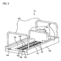
- FIG. 2 is a perspective view of the rack tray 10 according to Embodiment 1.
- the rack tray 10 roughly includes a tray base 10a , a rack dropout-preventing mechanism 10b , a rack movement-preventing mechanism 10c , a grip member 10d , and a guide rail 10e .
- the tray base 10a has a substrate 10g supporting the rack 9 , and guide walls 10f are arranged on three sides of the substrate 10g .
- the rack tray 10 has an opening in a side where the guide wall 10f is not formed, the rack dropout-preventing mechanism 10b projects into the opening to prevent the plurality of racks 9 stored on the tray base 10a from being dropped out of the opening.
- the grip members 10d are arranged on the opening and the guide wall 10f on the side opposing the opening, and a holding section of the grip member 10d is gripped to transport the rack tray 10 .
- the grip member 10d shown in FIG. 2 vertically rises from the guide wall 10f and bends at the holding section to form an inverted U- shape.
- the grip member 10d arranged on the opening may have a bent section that can be horizontally bent outside the tray base 10a in the middle of a vertically rising pipe to make it possible to offset the holding section outside the rack tray 10 .
- the grip member 10d is offset to make it easy to take in/out the rack 9 .
- the guide rail 10e is integrated with the tray base 10a and formed in parallel to the traveling direction of the arranged and held racks 10 .
- a trench 10i at a center section of the guide rail 10e and the trench 10i is provided for a shaft (will be described later) to travel.
- a plurality of engagement sections 10h are formed at positions corresponding to the number of racks to be stored on an upper surface of the guide rail 10e .
- the rack movement-preventing mechanism 10c is supported by the guide rail 10e by sandwiching the guide rail 10e from a side of a trench 10j (see FIG. 6 ).
- a projection 10p serving as a locking section of the rack movement-preventing mechanism 10c (will be described later) is engaged with the engagement section 10h formed on the guide rail 10e to lock the rack movement-preventing mechanism 10c . In this manner, the held rack 9 is prevented from moving.
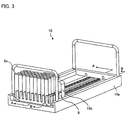
- FIG. 3 is a perspective view of the rack tray 10 in which the rack 9 holding the specimen container 9a is stored.
- FIG. 4 is a sectional view of the rack tray 10 in FIG. 3 along an A - A line.
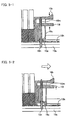
- FIGS. 5-1 and 5-2 are operational diagrams of the rack movement-preventing mechanism 10c .
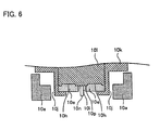
- FIG. . 6 is a cross-sectional view of the engagement section including the rack movement-preventing mechanism 10c and the guide rail 10e .
- the racks 9 holding the specimen containers 9a are arranged in the tray base 10a of the rack tray 10 in parallel from the opening and pushed on an opening side by the rack movement-preventing mechanism 10c to prevent the rack 9 from moving and falling.
- the rack movement-preventing mechanism 10c has a handle section including a partition 10k and a partition 101 , a push spring 10m is arranged between the partition 10k and the partition 101 to bias the partition 101 downward.
- the projection 10p is formed at a distal end of the partition 101 .
- the projection 10p is engaged between the plurality of engagement sections 10h arranged on the guide rail 10e at intervals each having a width of the rack 9 as one pitch.
- a shaft 10n extending to the lower section of the guide rail 10e is supported on the partition 101 , and an E ring 10o is attached between the shaft 10n and the partition 101 .
- the shaft 10n moves in the trench 10i formed between the guide rails 10e (see FIG. 2 , FIG. 4 , and FIG. 6 ).
- the shaft 10n serves a part of a lock canceling mechanism that cancels prevention of movement of the rack 9 by the rack movement-preventing mechanism 10c when the rack tray 10 is placed on the rack collecting section 8C .
- the engagement section 10h is designed such that an inclination of a slope on the opening side in the traveling direction of the rack 9 is set to be high and an inclination of the other slope is set to be low. For this reason, in order to move the rack movement-preventing mechanism 10c on the opening side in the traveling direction, the partition 10k or the partition 101 serving as a handle section may be pushed. However, when the partition 10k or the partition 101 is pushed in the opposite direction, the rack movement-preventing mechanism 10c cannot be moved to a rear side of the opening opposing the traveling direction, and backward movement is locked because the inclination of the engagement section 10h on the opening side is high. In order to move the rack movement-preventing mechanism 10c in a forward or backward direction, as shown in FIG.
- the partition 10k and the partition 101 serving as handle sections are gripped from the upper and lower sides and pushed. In this manner, the partition 101 is pushed up.
- the projection 10p at the distal end of the partition 101 rises.
- the engagement between the projection 10p of the rack movement-preventing mechanism 10c and the engagement section 10h on the guide rail 10e is canceled to make it possible to move the rack movement-preventing mechanism 10c on the guide rail 10e to the rear side of the opening.
- the rack 9 held and stored on the rack tray 10 is prevented by the rack dropout-preventing mechanism 10b and the rack movement-preventing mechanism 10c from moving in a forward or backward direction and prevented by the opposite guide walls 10f of the rack tray 10 from moving side to side.
- the rack 9 since upward movement is not inhibited, a part of the rack 9 is pulled up to make it possible to freely pick any one of the stored racks 9 from an arbitrary position of the rack tray 10 without moving the rack movement-preventing mechanism 10c , and the rack 9 can be very easily taken in or out.
- FIG. 7 is a perspective view of the rack collecting section 8C .
- FIGS. 8-1 and 8-2 are operational diagrams of lock cancellation of the rack movement-preventing mechanism 10c .
- the lock canceling mechanism of the rack movement-preventing mechanism 10c is arranged. As shown in FIG.
- the rack collecting section 8C includes a rack tray storing section 8c , a guide wall 8k, and a hole 8d, a push-up section 10t serving as a lock canceling mechanism of the rack movement-preventing mechanism 10c together with the shaft 10n is formed on the rack tray storing section 8c , and the projection section 8h serving as the lock canceling button of the rack dropout-preventing mechanism 10b (will be described later) projects from the hole 8d .
- the push-up section 10t is a narrow protrusion formed at a center section of the rack collecting section 8C in parallel to the rack traveling direction. As shown in FIG.
- the rack 9 is pushed to a side of the rack collecting section 8C with a push lever of the transport mechanism 8B , the unlocked rack movement-preventing mechanism 10c and the rack 9 are also moved in the direction opposing the opening of the rack tray 10 .
- FIG. 9 is a cross-sectional view of the rack tray 10 in FIG. 3 along a B - B line.
- the rack dropout-preventing mechanism 10b has a dropout-preventing lever 1 0s that prevents the rack 9 from being dropped out of the opening.
- the step-like planar dropout-preventing lever 10s horizontally extends under the substrate 10g and bent from a hole 10w (see FIG. 2 ) formed near the opening and vertically rises up to prevent the rack 9 from being dropped out.
- the dropout-preventing lever 10s is supported on the tray base 10a with a shaft 10q , a spring 10r is set between the bottom surface of the substrate 10g and the dropout-preventing lever 10s to upwardly bias an end section of the dropout-preventing lever 10s rising up from the hole 10w .
- a coil spring is used as the spring 10r
- a leaf spring a tension spring, or the like may be used.
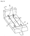
- FIG. 10 is a perspective view of the rack tray set section 8A .
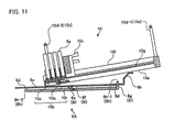
- FIG. 11 is a cross-sectional view of the rack tray set section 8A shown in FIG. 10 along a C - C line in the middle of placement of the rack tray 10 shown in FIG. 3 on the rack tray set section 8A .
- the rack tray set section 8A includes the rack tray storing section 8c , the guide wall 8k , and the hole 8d .
- the push-out lever 8a that pushes out the rack 9 on a side of the transport mechanism 8B is arranged, and the projection section 8h serving as the lock canceling button of the rack dropout-preventing mechanism 10b projects from the hole 8d .
- the projection sections 8h serving as the lock canceling buttons are also projected from two positions of the hole 8d near the guide wall 8k .
- the push-out lever 8a is generally built in the rack tray set section 8A before the rack tray 10 is arranged and travels through the trench 8b and the trench 10j of the rack tray 10 to push out the rack 9 on the opening side after the rack tray 10 is arranged.
- a lock canceling mechanism 8i of the rack dropout-preventing mechanism 10b arranged below the rack tray set section 8A includes a lock canceling lever 8g , a shaft 8f , and a spring 8e .
- the lock canceling lever 8g has a length almost equal to a length of the rack tray set section 8A in a rack traveling direction, and both the ends of the lock canceling lever 8g vertically rise to serve as projection sections 8h .
- the shaft 8f supports the lock canceling lever 8g in the rack tray set section 8C .
- the spring 8e biases a projection section 8h-1 on a guide wall side behind the rack tray set section 8A to push up the projection section 8h-1 .
- the projection section 8h-1 projects from the hole 8d on the rack tray storing section 8c .
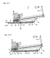
- FIGS. 12-1 to 12-4 are operational diagrams of a series of operations of setting the rack tray 10 in the rack tray set section 8A.
- the grip member 10d-1 is gripped to press the rack tray 10 to the side of the rack tray storing section 8c ( FIG. 12-1 ).
- the rack tray 10 slidably travels on the rack tray storing section 8c ( FIG. 12-2 ), and a rear end of the bottom section of the rack tray 10 travels to an upper side of the guide wall 8k .
- the guide wall 8k has a halfway inclined section, and the bottom section of the rack tray 10 slidably drops into the rack tray storing section 8c along the inclined section ( FIG. 12-3 ).
- a projection section 8h-1 projecting from the hole 8d is depressed by the weight of the rack tray 10 ( FIG. 12-4 ).
- the other end of the lock canceling lever 8g is pushed up by using the shaft 8f as a rotating axis, and a projection section 8h-2 at the other end of the lock canceling lever 8g projects from the hole 8d in the rack traveling direction.
- the rack movement-preventing mechanism 10c is moved to the backmost section by gripping and pressing the handle section including the partition 10k and the partition 101 .
- the push-out lever 8a built in the rack tray set section 8A is caused to travel to push the rack 9 out to the transport mechanism 8B , and the rack 9 is transported to the specimen dispenser 20 by the transport mechanism 8B.
- the rack tray set section 8A does not include the push-up section 10t serving as the lock canceling mechanism of the rack movement-preventing mechanism 10c .
- the rack tray set section 8A may include the push-up section 10t .
- the rack tray 10 having the rack dropout-preventing mechanism 10b is used, and the rack transport system 8 according to Embodiment 1 in which the projection sections 8h serving as the lock canceling button of the lock canceling mechanism 8i on the rack tray set section 8A is caused to project near the guide wall 8k behind the rack tray set section 8A can slide the rack tray 9 to place the rack tray 9 on the rack tray set section 8A , and the rack tray 9 can be safely and easily placed.
- the rack collecting section 8C includes the same lock canceling mechanism 8i as the lock canceling mechanism 8i of the rack tray set section 8A , and the projection section 8h serving as the lock canceling button of the rack dropout-preventing mechanism 10b on the rack collecting section 8C is caused to project near the guide wall 8k (see FIG. 7 ). Since the rack tray 10 on the rack collecting section 8C is to hold the rack 9 in which an almost empty specimen containers 9a is stored, it is lighter than the rack tray 10 placed on the rack tray set section 8A , and the necessity of slidably pulling up the rack tray 10 from the side when collecting is not high. Therefore, the lock canceling lever 8g of the lock canceling mechanism 8i need not have a length almost equal to the length in the rack traveling direction, and may be arranged near a rack transport entrance of the rack collecting section 8C.
- the rack transport system 8 having one rack tray set section 8A and one rack collecting section 8C has been described.
- the number of rack tray set sections and the number of rack collecting sections need only be equal to each other, and the system may have two or more rack tray set sections and two or more rack collecting sections.
- the automatic analyzing apparatus having the rack transport system 8 arranged on the right of the specimen dispenser 20 is illustrated.
- a rack tray 10a in which a side surface section, being in contact with a rack 9A , of the guide wall 10f of any one of the two sides parallel to the traveling direction of the rack 9 is hollowed out to form a fitting section 10x on the side surface section is illustrated.
- the fitting section 10x is formed on an entire lower section of the side surface being in contact with the substrate 10g of the guide wall 10f .
- the rack 9A having a projection section 9x fitted in the fitting section 10x is preferably stored.
- the rack tray 10a and the rack 9A are fitted through the fitting section 10x and the projection section 9x to make it possible to more stably transport the tray and set the tray in the apparatus.
- the fitting section 10x prevents the rack 9 from falling and moving together with the rack movement-preventing mechanism 10c .
- the fitting section 10x is a rectangular recessed section
- the projection section 9x is a rectangular proj ection section fitted in the recessed section.
- the fitting section 10x and the projection section 9x need only be fitted in each other, and trapezoidal shapes or the like may be employed.
- an automatic analyzing apparatus 1A including a rack transport system 8' as shown in FIG. 13-2 is used.
- the rack 9A and the rack tray 10a are horizontally asymmetrical because the projection section 9x and the fitting section 10x are formed, the rack 9A cannot be easily collected in the rack collecting section 8C when the rack trays 10a in the rack tray set section 8A and the rack collecting section 8C face each other. Therefore, when the rack 9A and the rack tray 10a are used, as shown in FIG. 13-2 , the arrangements of the rack tray set section 8A and the rack collecting section 8C need to be changed to change the rack transport system such that the rack trays 10a are arranged in the same direction. As another modification, a rack tray 10b shown in FIG. 14 is illustrated.
- a rack movement-preventing mechanism 10c' does not have the shaft 10n , and inclinations of two slopes of the engagement section 10h' on the guide rail 10e are set to be equal to each other.
- the rack movement-preventing mechanism 10c' can be moved in the forward or backward directions with the same force.
- the rack 9 is pushed with a push-out lever (not shown) of the transport mechanism 8B, the projection 10p runs on the engagement section 10h' to make it possible to cancel the lock state.
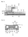
- FIG. 15 is a cross-sectional view of an engagement section including a rackmovement-preventing mechanism 10c" and a guide rail 10e' .
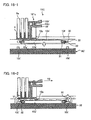
- FIG. 16-1 and FIG. 16-2 are sectional views showing a rack tray 10c together with the rack 9 and a rack collecting section 8C' .
- the rack tray 10c is considerably different from the rack tray 10 of Embodiment 1 in that the guide rail 10e' is formed independently of the tray base 10a' .
- the rack movement-preventing mechanism 10c" does not have a shaft 10n (see FIG. 4 ).
- the guide rail 10e' does not have the trench 10i through which the shaft 10n passes, and one engagement section 10h' is arranged at each position of the guide rail 10e' .
- the partition 10k' includes a projection 60 at the distal end thereof such that the partition 10k' is supported by a tray base 10a' not the guide rail 10e' , and the projection 60 is engaged with an engagement section 61 formed on the tray base 10a' .
- the guide rail 10e' is formed independently of the tray base 10a' and joined to the tray base 10a' through a joint member 30 .
- a spring 33 that biases to rise up the guide rail 10e' is arranged between the joint member 30 and the guide rail 10e' .
- the guide rail 10e' is joined to the joint member 30 by the joint section 31 and supported on the tray base 10a' by a shaft 32 serving as a joint section between the joint member 30 and the tray base 10a' .
- the shape of the engagement section 10h' on the guide rail 10e' and the engagement between the engagement section 10h' and the projection 10p of the partition 101' are the same as those in Embodiment 1 except that one engagement section 10h' is formed at each position on the guide rail 10e' .
- the partition 10k' or the partition 101' is pushed to make it possible to move the rack movement-preventing mechanism 10c" to the opening side of the rack tray 10c .
- the rack tray 10c includes the rack dropout-preventing mechanism 10b as in Embodiment 1.
- the rack transport system using the rack tray 10c like the rack transport system according to Embodiment 1, includes a rack tray set section, a transport mechanism, and a rack collecting section.
- the rack collecting section 8C' according to Embodiment 2 includes, in place of the push-up section 10t of the shaft 10n , a push-up section 10t ' that pushes up the joint member 30 of the rack tray 10c to push down the guide rail 10e' .
- the push-up section 10t ' is arranged on the rack collecting section 8C' under the joint member 30 .
- the push-up section 10t' When the rack tray 10c is arranged in the rack collecting section 8C' from above, the push-up section 10t' is brought into contact with an outer-side section of the joint member 30 , as indicated by an arrow Y1 in FIG. 16-2 , the push-up section 10t' pushes up the joint member 30 from the outside. With the push-up operation, the joint member 30 rotates by using the shaft 32 as a rotating axis to push down the guide rail 10e' . When the guide rail 10e' is pushed down, the engagement between the projection 10p at the distal end of the partition 101' and the engagement section 10h' is canceled to make it possible to move the rack movement-preventing mechanism 10c" in a backward direction (indicated by an arrow Y2).
- FIG. 17 is a sectional view of the rack tray 10D.
- a dropout-preventing lever 10s' of a rack dropout-preventing mechanism 10b' supported on the lower part of the substrate 10g of the tray base 10a by a shaft 10q' has a length almost equal to the length of the rack tray 10D in the rack traveling direction, and the shaft 10q' is arranged at the center section of the dropout-preventing lever 10s' .
- the spring 10r' like the rack tray 10 , is biased upward to raise up an end of the dropout-preventing lever 10s' from the hole 10w .
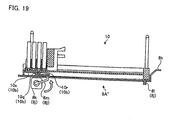
- FIG. 19 is a sectional view of a rack tray set section 8A " when the rack tray 10 is placed on the rack tray set section 8A" .
- the rack tray set section 8A" includes a lock canceling mechanism 8j of the rack dropout-preventing mechanism 10b , and the lock canceling mechanism 8j has a lock canceling lever 8m, a sensor 81 , and a motor 8k .
- the lock canceling lever 8m is a lever that pushes up the dropout-preventing lever 10s of the rack dropout-preventing mechanism 10b , and is arranged on a transporting mechanism side of the rack tray set section 8A" .
- the sensor 81 is a sensor that, when the rack tray 10 in which a plurality of racks are held and stored is slid and placed on the rack tray set section 8A ", detects the placement, and is arranged near the guide wall 8k behind the rack tray set section 8A ".
- the sensor 81 serves as a lock canceling button of the rack dropout-preventing mechanism 10b .
- the motor 8k pushes up the lock canceling lever 8m after the sensor 81 detects the placement of the rack tray 10 on the rack tray set section 8A" .
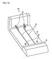
- the rack tray 10 can be placed on the rack tray set section 8A" by sliding the rack tray 10 . For this reason, the rack tray 10D can be safely and easily set.
- a rack transport system is effectively used in an automatic analyzing apparatus that optically measures a reaction between a specimen and a reagent to analyze components of the specimen.
- the rack transport system can be used in safe installation of a rack tray in which a plurality of racks supporting a plurality of specimen containers is arranged in an analyzing apparatus.
Landscapes
- Chemical & Material Sciences (AREA)
- Physics & Mathematics (AREA)
- Health & Medical Sciences (AREA)
- Life Sciences & Earth Sciences (AREA)
- Analytical Chemistry (AREA)
- Biochemistry (AREA)
- General Health & Medical Sciences (AREA)
- General Physics & Mathematics (AREA)
- Immunology (AREA)
- Pathology (AREA)
- Automatic Analysis And Handling Materials Therefor (AREA)
- Chemical Kinetics & Catalysis (AREA)
Abstract
Description
- The present invention relates to a rack transport system that transports a rack tray holding a plurality of racks.
- In the past, a dispenser or an automatic analyzing apparatus employs a system that transports a plurality of racks by using a rack tray that can arrange and hold the plurality of racks supporting a plurality of a specimen containers when supplying or collecting a specimen (for example, see Patent Reference 1).
- Patent Reference 1: Japanese Laid-Open Patent Publication No.
10-123146 - However, a rack tray disclosed in
Patent Reference 1 includes a rack dropout-preventing mechanism that prevents a rack to be stored from being dropped out when the rack tray is transported, and a rack tray set section of the rack transport system has a canceling mechanism of the rack dropout-preventing mechanism. However, since a lever of the canceling mechanism is arranged near a rack outlet port of the rack tray set section, the rack tray collides with a projection of a canceling lever when the rack tray is tried to be slid to be set in the tray placing section. For this reason, the rack tray needs to be placed from directly above. Thus, operability is very poor when a rack tray is being placed because a rack tray holding a plurality of specimen containers is heavy. - The present invention has been made in consideration of the above description and has as its objective to provide a rack transport system that horizontally slides a rack tray holding and storing a plurality of specimen containers to make it possible to safely place the rack tray on a rack tray set section.
- In order to solve the problem and to achieve the objective, a rack transport system according to the present invention is a rack transport system using a rack tray having a rack dropout-preventing mechanism including a dropout-preventing lever, a shaft that supports the dropout-preventing lever on a rack tray, and a spring that biases the dropout-preventing lever upward about the shaft to cause the dropout-preventing lever to project from a rack tray opening to prevent a rack from dropping out, the system characterized by including: a rack tray set section that has a lock canceling mechanism of the rack dropout-preventing mechanism and on which the rack tray that arranges and holds a plurality of racks supporting a plurality of specimen containers is placed; a rack collecting section on which an empty rack tray is placed and the rack collecting section collects the racks supporting the specimen containers obtained after a dispensing operation is performed; and a transporting mechanism that transports the rack from the rack tray set section to a dispensing mechanism and transports the rack to the rack collecting section after a specimen is dispensed from the specimen container, wherein a lock canceling button of the lock canceling mechanism is formed at a position where the rack tray that holds and stores the plurality of racks supporting the plurality of specimen containers is slid to be able to be set in the rack tray set section.
- The rack transport system according to the present invention, in the above invention, is characterized in that the rack tray set section includes a storing section that stores a rack tray, and the rack tray is slid from an upper side of a guide wall behind the storing section and placed on the rack tray set section.
- The rack transport system according to the present invention, in the above invention, is characterized in that the lock canceling button is formed near the guide wall behind the rack tray set section.
- The rack transport system according to the present invention, in the above invention, is characterized in that the dropout-preventing lever has a length almost equal to a length of the rack tray in a rack traveling direction.
- The rack transport system according to the present invention, in the above invention, is characterized in that the lock canceling mechanism includes a lock canceling lever having a length almost equal to a length of the rack tray set section in a rack traveling direction, a shaft that supports the lock canceling lever on the rack tray set section, and a spring that biases a lock canceling lever end on a guide wall side behind the rack tray set section to push up the lock canceling lever end, both ends of the lock canceling lever have projection sections that vertically rise, the projection section on the guide wall side behind the rack tray set section is the lock canceling button, and a hole to protrude the projection section therethrough is formed in the rack tray storing section of the rack tray set section.
- The rack transport system according to the present invention, in the above invention, is characterized in that the spring biases the lock canceling lever end on the guide wall side behind the rack tray set section to push up the lock canceling lever end to protrude the projection from the hole, and, when the rack tray that holds and stores a plurality of racks is slid to be placed on the rack tray set section, the projection section is pushed down by placing the rack tray, and the projection section at the other end is pushed up to cancel the lock state of the rack movement-preventing mechanism.
- The rack transport system according to the present invention, in the above invention, is characterized in that the lock canceling mechanism includes a lock canceling lever arranged on a side of the transporting mechanism of the rack tray set section, a sensor that is arranged near the guide wall behind the rack tray set section and, when the rack tray that holds and stores a plurality of racks is slid and placed on the rack tray set section, detects the placement, and a motor that pushes up the lock canceling lever after the sensor detects the placement of the rack tray on the rack tray set section, wherein the sensor is the lock canceling button.
- The rack transport system according to the present invention, in the above invention, is characterized in that the rack collecting section includes the lock canceling mechanism of the rack dropout-preventing mechanism.
- The rack transport system according to the present invention, in the above invention, is characterized in that the rack tray includes a tray base that holds and stores a plurality of racks, and a rack movement-preventing mechanism that moves on the tray base and presses the plurality of racks arranged on the tray base to a side of the rack dropout-preventing mechanism.
- The rack transport system according to the present invention, in the above invention, is characterized in that the rack tray includes a guide rail having a plurality of engagement sections at positions corresponding to the number of racks held and stored on the tray base, and a locking section held by the rack movement-preventing mechanism is engaged with the engagement section to lock the movement of the rack in the backward direction of the rack tray opening.
- The rack transport system according to the present invention, in the above invention, is characterized in that the engagement section is a projection formed on the guide rail, an inclination of a slope on a side of the rack tray opening is set to be high, and an inclination of the other slope is to be low.
- The rack transport system according to the present invention, in the above invention, is characterized in that the rack movement-preventing mechanism includes a handle section that pushes up the locking section, the handle section is gripped and pressed to push up the locking section to cancel the engagement with the engagement section, and the rack movement-preventing mechanism is moved.
- The rack transport system according to the present invention, in the above invention, is characterized by comprising grip members on two opposite sides parallel to an arrangement direction of the racks on the tray base.
- The rack transport system according to the present invention, in the above invention, is characterized in that the rack movement-preventing mechanism includes a shaft supported by the handle section and extending to a lower section of the guide rail, and the guide rail includes a trench section through which the shaft passes with movement of the rack movement-preventing mechanism.
- The rack transport system according to the present invention, in the above invention, is characterized in that the guide rail is formed independently of the tray base, joined to the tray base by a joint member, and a spring that biases the guide rail to push up the guide rail is arranged between the joint member and the guide rail.
- The rack transport system according to the present invention, in the above invention, is characterized in that the tray base includes guide walls on three sides except for the opening in the rack traveling direction, and a guide wall of any one of two sides parallel to the traveling direction has a fitting section fitted on the rack formed on a side surface thereof.
- The rack transport system according to the present invention, in the above invention, is characterized in that a rack having a projection section that is fitted in the fitting section of the guide wall is held and stored.
- The rack transport system according to the present invention, in the above invention, is characterized in that the grip member arranged on an opening of the rack in the traveling direction is arranged such that a holding section is offset from an arrangement position of the grip member.
- The rack transport system according to the present invention, in the above present invention, is characterized in that the rack collecting section includes a lock canceling mechanism of the rack movement-preventing mechanism.
- The rack transport system according to the present invention, in the above invention, is characterized in that the lock canceling mechanism of the rack movement-preventing mechanism is a push-up member that pushes up the shaft of the rack tray.
- The rack transport system according to the present invention, in the above invention, is characterized in that the lock canceling mechanism of the rack movement-preventing mechanism is a push-up member that pushes up the joint member of the rack tray to push down the guide rail.
- According to the present invention, since a lock canceling button that cancels the locking of a rack dropout-preventing mechanism is formed near a guide wall behind a rack tray set section to make it possible to slide and place a rack tray holding and storing a plurality of racks supporting a plurality of specimen containers on the rack tray set section, the rack transport system can be easily and safely operated.
-
-
FIG. 1 is a pattern diagram showing a main part configuration of an automatic analyzing apparatus using a rack tray according toEmbodiment 1. -
FIG. 2 is a perspective view of a rack tray according toEmbodiment 1. -
FIG. 3 is a perspective view of a rack tray that stores racks holding specimen containers. -
FIG. 4 is a sectional view of the rack tray shown inFIG. 3 along an A - A line. -
FIG. 5-1 is an operational diagram of a rack movement-preventing mechanism according toEmbodiment 1. -
FIG. 5-2 is an operational diagram of a rack movement-preventing mechanism according toEmbodiment 1. -
FIG. 6 is a cross-sectional view of an engagement section including the rack movement-preventing mechanism and a guide rail according toembodiment 1. -
FIG. 7 is a perspective view of a rack collecting section according toEmbodiment 1. -
FIG. 8-1 is an operational diagram of the lock cancellation of the rack movement-preventing mechanism according toEmbodiment 1. -
FIG. 8-2 is an operational diagram of the lock cancellation of the rack movement-preventing mechanism according toEmbodiment 1. -
FIG. 9 is a sectional view of the rack tray shown inFIG. 3 along a B - B line. -
FIG. 10 is a perspective view of a rack tray set section according toEmbodiment 1. -
FIG. 11 is a cross-sectional view of the rack tray shown inFIG. 3 along a C - C line in the middle of placement of the rack tray on the rack tray set section inFIG. 10 . -
FIG. 12-1 is an operational diagram 1 of a series of operations of setting a rack tray in the rack tray set section according toEmbodiment 1. -
FIG. 12-2 is an operational diagram 2 of a series of operations of setting a rack tray in the rack tray set section according toEmbodiment 1. -
FIG. 12-3 is an operational diagram 3 of a series of operations of setting a rack tray in the rack tray set section according toEmbodiment 1. -
FIG. 12-4 is an operational diagram 4 of a series of operations of setting a rack tray in the rack tray set section according toEmbodiment 1. -
FIG. 13-1 is a frontview showing Modification 1 of the rack tray according toEmbodiment 1. -
FIG. 13-2 is a pattern diagram showing a main part configuration of an automatic analyzing apparatus using the rack tray according to a modification ofEmbodiment 1. -
FIG. 14 is a sectionalview showing Modification 2 of the rack tray according toEmbodiment 1 together with a rack and a rack collecting section. -
FIG. 15 is a cross-sectional view of an engagement section including a rack movement-preventing mechanism according toModification 3 ofEmbodiment 1 and a guide rail. -
FIG. 16-1 is a cross-sectional view of a rack tray according toModification 3 ofEmbodiment 1 together with a rack and a rack collecting section. -
FIG. 16-2 is a cross-sectional view of the rack tray according toModification 3 ofEmbodiment 1 together with a rack and a rack collecting section. -
FIG. 17 is a sectional view of a rack tray according to Modification 4 ofEmbodiment 1. -
FIG. 18 is a perspective view of a rack tray set section according to Modification 4 ofEmbodiment 1. -
FIG. 19 is a sectional view of a rack tray set section according toEmbodiment 2. -
- 1, 1A
- Automatic analyzing apparatus
- 2, 3
- First and second reagent storage
- 2a, 3a
- Reagent container
- 4
- Reaction table
- 4a
- Holding section
- 4b
- Optical path
- 5
- Reaction container
- 6, 7
- First and second reagent dispenser
- 6a, 7a
- Arm
- 6b, 7b
- Probe
- 8, 8'
- Rack transport system
- 8a
- Push-out lever
- 8c
- Rack tray storing section
- 8d
- Hole
- 8e
- Spring
- 8f
- Shaft
- 8g
- Lock canceling lever
- 8h, 8h'
- Projection section
- 8i
- Lock canceling mechanism
- 8k
- Guide wall
- 8A, 8A', 8A"
- Rack tray set section
- 8B, 8B'
- Transport mechanism
- 8C
- Rack collecting section
- 9, 9A
- Rack
- 9a
- Specimen container
- 10, 10A, 10B, 10C, 10D
- Rack tray
- 10a
- Tray base
- 10b, 10b'
- Rack dropout-preventing mechanism
- 10c, 10c', 10c"
- Rack movement-preventing mechanism
- 10d
- Grip member
- 10e, 10e'
- Guide rail
- 10f
- Guide wall
- 10g
- Substrate
- 10h, 61
- Engagement section
- 8b, 10i, 10j
- Trench
- 10k, 101, 10k', 101'
- Partition
- 10m, 10r, 33
- Spring
- 10n, 10q, 32
- Shaft
- 10o
- E ring
- 10p, 60
- Projection
- 10s, 10s'
- Dropout-preventing lever
- 10t, 10t'
- Push-up section
- 11
- Analytical optical system
- 12
- Cleaning mechanism
- 13, 14
- First and second stirring device
- 15
- Control section
- 16
- Input section
- 17
- Analyzing section
- 18
- Memory section
- 19
- Output section
- 20
- Specimen dispenser
- 30
- Joint member
- 31
- Joint section
- 40
- Measuring mechanism
- 50
- Control mechanism
- With reference to the accompanying drawings, a rack transport system according to the embodiments of the present invention will be described below by using, as an example, an automatic analyzing apparatus that analyzes a liquid specimen such as blood as a sample. Drawings referred to in the following explanation are representative. When the same object is shown in different drawings, the dimensions, scales and the like of the object may be different from each other. The invention is not limited to the embodiments. In the drawings, the same parts are denoted by the same reference numerals.
-
FIG. 1 is a pattern diagram showing a configuration of anautomatic analyzing apparatus 1 using arack transport system 8 according toEmbodiment 1. As shown inFIG. 1 , theautomatic analyzing apparatus 1 includes ameasuring mechanism 40 that dispenses a specimen to be analyzed and a reagent intoreaction containers 5, respectively, and optically measures reactions occurring in thereaction containers 5 into which the specimen and the reagent are dispersed, and acontrol mechanism 50 that controls the entireautomatic analyzing apparatus 1 including themeasuring mechanism 40 and analyzes measurement results in themeasuring mechanism 40. Theautomatic analyzing apparatus 1 automatically performs biochemical, immunological, or genetical analysis of a plurality of specimens by the incorporation of the two mechanisms. - The measuring
mechanism 40 includes afirst reagent storage 2, asecond reagent storage 3, a reaction table 4, afirst reagent dispenser 6, asecond reagent dispenser 7, arack transport system 8, an analyticaloptical system 11, acleaning mechanism 12, afirst stirring device 13, asecond stirring device 14, and aspecimen dispenser 20. - In the
first reagent storage 2, as shown inFIG. 1 , a plurality ofreagent containers 2a that store first reagents are arranged in a circumferential direction. Thefirst reagent storage 2 is rotated by driving means (not shown) to transport thereagent containers 2a in the circumferential direction. The plurality ofreagent containers 2a is filled with reagents depending on inspection items, respectively. Information recording media (not shown), on which information such as types, lots, expiration dates of the stored reagents are recorded, are stuck on outer surfaces of thereagent containers 2a. In this case, on a periphery of thefirst reagent storage 2, a reading device (not shown) that reads the reagent information recorded on the information recording medium stuck on thereagent container 2a and outputs the reagent information to acontrol section 15 is installed. Above thefirst reagent storage 2, an openable and closable lid (not shown) is arranged to suppress the reagent from being evaporated or transformed. A constant temperature tank (not shown) for cooling reagent is arranged below thefirst reagent storage 2. - In the
second reagent storage 3, as shown inFIG. 1 , a plurality ofreagent containers 3a that store second reagents are arranged in a circumferential direction. Like thefirst reagent storage 2, thesecond reagent storage 3 is rotated by driving means (not shown) to transport thereagent containers 3a in the circumferential direction. The plurality ofreagent containers 3a is filled with reagents depending on inspection items, respectively. Information recording media (not shown), on which information such as types, lots, expiration dates of the stored reagents are recorded, are stuck on outer surfaces of thereagent containers 3a. In this case, on a periphery of thesecond reagent storage 3, a reading device (not shown) that reads the reagent information recorded on the information recording medium stuck on thereagent container 3a and outputs the reagent information to thecontrol section 15 is installed. Above thesecond reagent storage 3, an openable and closable lid (not shown) is arranged to suppress the reagent from being evaporated or transformed. A constant temperature tank (not shown) for cooling reagent is arranged below thesecond reagent storage 3. - On the reaction table 4, as shown in
FIG. 1 , a plurality ofreaction containers 5 are arranged along a circumferential direction. The reaction table 4 is rotated by driving means (not shown) different from the driving means that drives the first andsecond reagent storages reaction container 5 in the circumferential direction. The reaction table 4 is arranged between alight source 11a and anoptical splitter 11b and has aholding section 4a that holds thereaction container 5 and anoptical path 4b formed by a circular opening that guides a beam emitted from thelight source 11a to theoptical splitter 11b. The holdingsections 4a are arranged at predetermined intervals on the periphery of the reaction table 4 along a circumferential direction, and have theoptical path 4b circumferentially extending on an inner circumferential side of the holdingsection 4a formed therein. An openable and closable lid (not shown) is arranged above the reaction table 4, and a constant temperature tank (not shown) to heat the reaction table 4 to a temperature at which a reaction between a specimen and a reagent is accelerated is arranged below the reaction table 4. - The
reaction container 5 is a container, called a cuvette, shaped as a rectangular tube by an optically transparent material, for example, glass including heat-resistant glass, cyclic olefin, or polystyrene that transmits 80% or more of light included in light for analysis (340 to 800 nm) emitted from the analyticaloptical system 11. - The
first reagent dispenser 6 includes anarm 6a that vertically moves and rotates about a vertical line passing through a proximal end of thearm 6a freely. At a distal end of thearm 6a, aprobe 6b that sucks and discharges a specimen is attached. Thefirst reagent dispenser 6 includes a breathing mechanism using a breathing syringe or a piezoelectric element (not shown). Thefirst reagent dispenser 6 sucks the first reagent with theprobe 6b from thereagent container 2a moved to a predetermined position on thefirst reagent storage 2 described above, swings thearm 6a in a clockwise direction in the drawing and discharges the first reagent into thereaction container 5 to perform a dispensing operation. On a pivotal trace of theprobe 6b, acleaning tank 6d that cleans theprobe 6b with cleaning water is installed. - The
second reagent dispenser 7 includes anarm 7a that vertically moves and rotates about a vertical line passing through a proximal end of thearm 7a freely. At a distal end of thearm 7a, aprobe 7b that sucks and discharges a specimen is attached. Thesecond reagent dispenser 7 includes a breathing mechanism using a breathing syringe or a piezoelectric element (not shown). Thesecond reagent dispenser 7 sucks the second reagent with theprobe 7b from thereagent container 3a moved to a predetermined position on thesecond reagent storage 3 described above, swings thearm 7a in a counterclockwise direction in the drawing and discharges the second reagent into thereaction container 5 to perform a dispensing operation. On a pivotal trace of theprobe 7b, acleaning tank 7d that cleans theprobe 7b with cleaning water is installed. - The analytical
optical system 11 is an optical system that causes light for analysis (340 to 800 nm) to transmit through a liquid sample in thereaction container 5 obtained by reaction between the reagent and the specimen to perform analysis, and has thelight source 11a, theoptical splitter 11b, and a light-receivingsection 11c. The light for analysis emitted from thelight source 11a transmits through the liquid sample in thereaction container 5 and is received by the light-receivingsection 11c arranged at a position opposing theoptical splitter 11b. - In the first and
second stirring devices rods - In the
cleaning mechanism 12,nozzle 12a sucks and discharges a reaction fluid in thereaction container 5 measured by the analyticaloptical system 11 and pours and sucks a cleaning solution such as a cleaner or a cleaning fluid to perform cleaning. Although the cleanedreaction container 5 is recycled, thereaction container 5 may be discarded depending on the inspection of contents after measurement is performed once. - The
specimen dispenser 20 includes anarm 20a that vertically moves and rotates about a vertical line passing through a proximal end of thearm 20a freely. At a distal end of thearm 20a, aprobe 20b that sucks and discharges a specimen is attached. Thespecimen dispenser 20 includes a breathing mechanism using a breathing syringe or a piezoelectric element (not shown). Thespecimen dispenser 20 sucks the specimen with theprobe 20b from thespecimen container 9a moved to a dispensing position by the rack transport system 8 (will be described below), swings thearm 20a in a clockwise direction in the drawing, and discharges the specimen into thereaction container 5 to perform a dispensing operation. On a pivotal trace of theprobe 20b, acleaning tank 20d that cleans theprobe 20b with cleaning water is installed. - The
rack transport system 8, as shown inFIG. 1 , includes a rack tray setsection 8A on which arack tray 10 in which a plurality ofracks 9 supporting a plurality ofspecimen containers 9a are arranged and held is placed, arack collecting section 8C on which anempty rack tray 10 is placed and the rack collecting section collects a rack supporting a specimen container the dispensing operation of which is finished, and atransport mechanism 8B that transports therack 9 pushed out of the rack tray setsection 8A with a push-outlever 8a to the dispensing position of thespecimen dispenser 20 and transports therack 9 to therack collecting section 8C after the specimen is dispensed by thespecimen dispenser 20 from all thespecimen containers 9a supported by therack 9. - In order to supply the
specimen container 9a to thespecimen dispenser 20, therack tray 10 is placed on the rack tray setsection 8A, the plurality ofracks 9 set in therack tray 10 by thetransport mechanism 8B are transported by the push-outlever 8a in a first direction indicated by an arrow D1 to sequentially send the plurality ofracks 9 to thetransport mechanism 8B. The push-outlever 8a is transported by transporting means such as a belt conveyor (not shown). Thetransport mechanism 8B transports therack 10 sent with the push-outlever 8a to the dispensing position of thespecimen dispenser 20 while stepping therack 10 along thetransport mechanism 8B extending to thespecimen dispenser 20. In therack tray 10, before being arranged in therack transport system 8, the rack dropout-preventingmechanism 10b projects into the opening of therack tray 10 to prevent therack 9 from being dropped out of the opening (seeFIG. 2 ). However, when therack tray 10 is arranged in the rack tray setsection 8A, aprojection section 8h (seeFIG. 10 ) serving as a lock canceling button of the rack dropout-preventing mechanism on a rack tray setsection 8A (will be described later) is depressed to cancel the lock state of the rack dropout-preventing mechanism, and therack 9 can be transported with a push-outlever 8a from the opening to thetransport mechanism 8B. - After the specimen is dispensed by the
specimen dispenser 20 from thespecimen container 9a supported by therack 9, thetransport mechanism 8B transports therack 9 from the dispensing position of thespecimen dispenser 20 to a position opposing therack collecting section 8C. Therack 9 is pushed out of thetransport mechanism 8B to therack collecting section 8C with a push-out lever (not shown) in a direction indicated by an arrow D2 and collected by therack tray 10. Like the rack tray setsection 8A, therack collecting section 8C includes theprojection section 8h (seeFIG. 7 ) serving as the lock canceling button of the rack dropout prevention canceling mechanism. When theempty rack tray 10 is set in therack collecting section 8C, the rack dropout-preventingmechanism 10c is unlocked to make it possible to transport therack 9 from thetransport mechanism 8B to therack collecting section 8C with a push-out lever (not shown). - The
control mechanism 50 includes thecontrol section 15, aninput section 16, the analyzing section 17, amemory section 18, and anoutput section 19. Thecontrol section 15 is connected to each section included in themeasuring mechanism 40 and thecontrol mechanism 50. As thecontrol section 15, a microcomputer or the like is used to control operations of each section. Thecontrol section 15 performs predetermined input/output control about information input/output in/from each constituent part and performs predetermined information processing on the information.
Thecontrol section 15 controls operations of each section of theautomatic analyzing apparatus 1 and, when an expiration date or the like of the reagent is out of a set range on the basis of the information read from the information recording medium, controls theautomatic analyzing apparatus 1 to stop an analyzing operation or gives an alarm to an operator. Thecontrol section 15 also functions as a transport control section that controls an operation of therack transport system 8. - The
input section 16 is constituted by using a keyboard, a mouse, or the like and acquires various pieces of information required for an analysis of a specimen, instruction information of an analyzing operation from the outside. The analyzing section 17 arithmetically operates an absorbance or the like on the basis of a measurement result acquired from the analyticaloptical system 11 to perform a constituent analysis of a specimen or the like. Thememory section 18 is configured to store various pieces of information including analysis results of the specimen or the like by using a hard disk that magnetically stores information and a memory that, when theautomatic analyzing apparatus 1 executes processing, loads various programs related to that processing from the hard disk and electrically stores the various programs. Thememory section 18 may include an auxiliary memory device that can read information stored in a storage medium such as a CD-ROM, a DVD-ROM, or a PC card. Theoutput section 19 is configured by using a printer, a communication mechanism, or the like, and outputs various pieces of information including an analysis result of the specimen to notify a user. - In the
automatic analyzing apparatus 1 configured as described above, after thefirst reagent dispenser 6 dispenses a first reagent in thereagent container 2a to the plurality ofreaction containers 5 sequentially transported in line, thespecimen dispenser 20 dispenses the specimen in thespecimen container 9a, thesecond reagent dispenser 7 dispenses a second reagent in thereagent container 3a, and the analyticaloptical system 11 measures a spectroscopic intensity of a sample obtained by a reaction between a specimen and a reagent. The measurement result is analyzed by the analyzingsection 18 to automatically perform a constituent analysis of the specimen or the like. Thereaction container 5 that is transported after the measurement by the analyticaloptical system 11 is finished is cleaned by thecleaning mechanism 12 while thereaction container 5 is being transported, thereby a series of analyzing operations are continuously repeated. - The
rack tray 10 according toEmbodiment 1 will be described below in detail with reference toFIG. 2. FIG. 2 is a perspective view of therack tray 10 according toEmbodiment 1. Therack tray 10 roughly includes atray base 10a, a rack dropout-preventingmechanism 10b, a rack movement-preventingmechanism 10c, agrip member 10d, and aguide rail 10e. Thetray base 10a has asubstrate 10g supporting therack 9, and guidewalls 10f are arranged on three sides of thesubstrate 10g. Therack tray 10 has an opening in a side where theguide wall 10f is not formed, the rack dropout-preventingmechanism 10b projects into the opening to prevent the plurality ofracks 9 stored on thetray base 10a from being dropped out of the opening.
Thegrip members 10d are arranged on the opening and theguide wall 10f on the side opposing the opening, and a holding section of thegrip member 10d is gripped to transport therack tray 10. Thegrip member 10d shown inFIG. 2 vertically rises from theguide wall 10f and bends at the holding section to form an inverted U- shape. However, thegrip member 10d arranged on the opening may have a bent section that can be horizontally bent outside thetray base 10a in the middle of a vertically rising pipe to make it possible to offset the holding section outside therack tray 10. Thegrip member 10d is offset to make it easy to take in/out therack 9. Theguide rail 10e is integrated with thetray base 10a and formed in parallel to the traveling direction of the arranged and held racks 10. There is atrench 10i at a center section of theguide rail 10e and thetrench 10i is provided for a shaft (will be described later) to travel. A plurality ofengagement sections 10h are formed at positions corresponding to the number of racks to be stored on an upper surface of theguide rail 10e. The rack movement-preventingmechanism 10c is supported by theguide rail 10e by sandwiching theguide rail 10e from a side of atrench 10j (seeFIG. 6 ). Aprojection 10p (seeFIG. 4 ) serving as a locking section of the rack movement-preventingmechanism 10c (will be described later) is engaged with theengagement section 10h formed on theguide rail 10e to lock the rack movement-preventingmechanism 10c. In this manner, the heldrack 9 is prevented from moving. - The rack movement-preventing
mechanism 10c will be described below with reference to the drawing.FIG. 3 is a perspective view of therack tray 10 in which therack 9 holding thespecimen container 9a is stored.FIG. 4 is a sectional view of therack tray 10 inFIG. 3 along an A - A line.FIGS. 5-1 and 5-2 are operational diagrams of the rack movement-preventingmechanism 10c.FIG. .6 is a cross-sectional view of the engagement section including the rack movement-preventingmechanism 10c and theguide rail 10e. - As shown in
FIG. 3 , theracks 9 holding thespecimen containers 9a are arranged in thetray base 10a of therack tray 10 in parallel from the opening and pushed on an opening side by the rack movement-preventingmechanism 10c to prevent therack 9 from moving and falling. As shown inFIG. 4 , the rack movement-preventingmechanism 10c has a handle section including apartition 10k and apartition 101, apush spring 10m is arranged between thepartition 10k and thepartition 101 to bias thepartition 101 downward. Theprojection 10p is formed at a distal end of thepartition 101. Theprojection 10p is engaged between the plurality ofengagement sections 10h arranged on theguide rail 10e at intervals each having a width of therack 9 as one pitch. Ashaft 10n extending to the lower section of theguide rail 10e is supported on thepartition 101, and an E ring 10o is attached between theshaft 10n and thepartition 101. In the movement of the rack movement-preventingmechanism 10c, theshaft 10n moves in thetrench 10i formed between theguide rails 10e (seeFIG. 2 ,FIG. 4 , andFIG. 6 ). Theshaft 10n serves a part of a lock canceling mechanism that cancels prevention of movement of therack 9 by the rack movement-preventingmechanism 10c when therack tray 10 is placed on therack collecting section 8C. - The
engagement section 10h is designed such that an inclination of a slope on the opening side in the traveling direction of therack 9 is set to be high and an inclination of the other slope is set to be low. For this reason, in order to move the rack movement-preventingmechanism 10c on the opening side in the traveling direction, thepartition 10k or thepartition 101 serving as a handle section may be pushed. However, when thepartition 10k or thepartition 101 is pushed in the opposite direction, the rack movement-preventingmechanism 10c cannot be moved to a rear side of the opening opposing the traveling direction, and backward movement is locked because the inclination of theengagement section 10h on the opening side is high. In order to move the rack movement-preventingmechanism 10c in a forward or backward direction, as shown inFIG. 5-1 , thepartition 10k and thepartition 101 serving as handle sections are gripped from the upper and lower sides and pushed. In this manner, thepartition 101 is pushed up. When thepartition 101 is pushed up, as shown inFIG. 5-2 , theprojection 10p at the distal end of thepartition 101 rises. When thepartition 101 is pushed up, the engagement between theprojection 10p of the rack movement-preventingmechanism 10c and theengagement section 10h on theguide rail 10e is canceled to make it possible to move the rack movement-preventingmechanism 10c on theguide rail 10e to the rear side of the opening. Therack 9 held and stored on therack tray 10 is prevented by the rack dropout-preventingmechanism 10b and the rack movement-preventingmechanism 10c from moving in a forward or backward direction and prevented by theopposite guide walls 10f of therack tray 10 from moving side to side. However, since upward movement is not inhibited, a part of therack 9 is pulled up to make it possible to freely pick any one of the storedracks 9 from an arbitrary position of therack tray 10 without moving the rack movement-preventingmechanism 10c, and therack 9 can be very easily taken in or out. - A lock canceling mechanism of the rack movement-preventing
mechanism 10c will be described below with reference toFIG. 7 ,FIG. 8-1 , andFIG. 8-2 .FIG. 7 is a perspective view of therack collecting section 8C.FIGS. 8-1 and 8-2 are operational diagrams of lock cancellation of the rack movement-preventingmechanism 10c.
When therack tray 10 is set on therack collecting section 8C to collect therack 9, the locked rack movement-preventingmechanism 10c hinders therack 9 from being collected. Therefore, in order to save the trouble of manually moving the rack movement-preventingmechanism 10c, the lock canceling mechanism of the rack movement-preventingmechanism 10c is arranged. As shown inFIG. 7 , therack collecting section 8C includes a racktray storing section 8c, aguide wall 8k, and ahole 8d, a push-upsection 10t serving as a lock canceling mechanism of the rack movement-preventingmechanism 10c together with theshaft 10n is formed on the racktray storing section 8c, and theprojection section 8h serving as the lock canceling button of the rack dropout-preventingmechanism 10b (will be described later) projects from thehole 8d. The push-upsection 10t is a narrow protrusion formed at a center section of therack collecting section 8C in parallel to the rack traveling direction. As shown inFIG. 8-1 , when therack tray 10 is arranged on therack collecting section 8C, theshaft 10n extending to the lower section of theguide rail 10e is brought into contact with the push-upsection 10t on therack collecting section 8C and pushed up. When theshaft 10n is pushed up, thepartition 101 fixed to theshaft 10n is also pushed up. For this reason, as shown inFIG. 8-2 , theprojection 10p at the distal end of thepartition 101 is lifted up to cancel the engagement with theengagement section 10h on theguide rail 10e. With the lock cancelling of the rack movement-preventingmechanism 10c, the rack movement-preventingmechanism 10c can be moved in a direction opposing the opening without gripping and pressing thepartition 10k and thepartition 101 serving as the handle sections from upper and lower sides. In this manner, therack 9 is pushed to a side of therack collecting section 8C with a push lever of thetransport mechanism 8B, the unlocked rack movement-preventingmechanism 10c and therack 9 are also moved in the direction opposing the opening of therack tray 10. - The rack dropout-preventing
mechanism 10b will be described below with reference to the drawings.FIG. 9 is a cross-sectional view of therack tray 10 inFIG. 3 along a B - B line. As shown inFIG. 9 , the rack dropout-preventingmechanism 10b has a dropout-preventinglever 10s that prevents therack 9 from being dropped out of the opening. The step-like planar dropout-preventinglever 10s horizontally extends under thesubstrate 10g and bent from ahole 10w (seeFIG. 2 ) formed near the opening and vertically rises up to prevent therack 9 from being dropped out. The dropout-preventinglever 10s is supported on thetray base 10a with ashaft 10q, aspring 10r is set between the bottom surface of thesubstrate 10g and the dropout-preventinglever 10s to upwardly bias an end section of the dropout-preventinglever 10s rising up from thehole 10w. InFIG. 9 , although a coil spring is used as thespring 10r, a leaf spring, a tension spring, or the like may be used. - With reference to
FIG. 10 andFIG. 11 , the lock canceling mechanism of the rack dropout-preventingmechanism 10b will be described below.FIG. 10 is a perspective view of the rack tray setsection 8A.FIG. 11 is a cross-sectional view of the rack tray setsection 8A shown inFIG. 10 along a C - C line in the middle of placement of therack tray 10 shown inFIG. 3 on the rack tray setsection 8A. As shown inFIG. 10 , the rack tray setsection 8A includes the racktray storing section 8c, theguide wall 8k, and thehole 8d. On the racktray storing section 8c, the push-outlever 8a that pushes out therack 9 on a side of thetransport mechanism 8B is arranged, and theprojection section 8h serving as the lock canceling button of the rack dropout-preventingmechanism 10b projects from thehole 8d. InEmbodiment 1, since the rack dropout-preventingmechanisms 10b are formed at two positions (left and right), theprojection sections 8h serving as the lock canceling buttons are also projected from two positions of thehole 8d near theguide wall 8k. The push-outlever 8a is generally built in the rack tray setsection 8A before therack tray 10 is arranged and travels through thetrench 8b and thetrench 10j of therack tray 10 to push out therack 9 on the opening side after therack tray 10 is arranged. - As shown in
FIG. 11 , a lock canceling mechanism 8i of the rack dropout-preventingmechanism 10b arranged below the rack tray setsection 8A includes alock canceling lever 8g, ashaft 8f, and aspring 8e. Thelock canceling lever 8g has a length almost equal to a length of the rack tray setsection 8A in a rack traveling direction, and both the ends of thelock canceling lever 8g vertically rise to serve asprojection sections 8h. Theshaft 8f supports thelock canceling lever 8g in the rack tray setsection 8C. Thespring 8e biases aprojection section 8h-1 on a guide wall side behind the rack tray setsection 8A to push up theprojection section 8h-1. In this manner, theprojection section 8h-1 projects from thehole 8d on the racktray storing section 8c. When a user places therack tray 10 in which the plurality ofracks 9 storing thespecimen containers 9a are stored on the rack tray setsection 8A, the user places the rack tray set 10 on a side of agrip member 10d-2 on which theracks 9 of therack tray 10 are held and stored on the racktray storing section 8c of the rack tray setsection 8A, set the bottom section of therack tray 10 on a side of agrip member 10d-1 on theguide wall 8k, and grips and presses thegrip member 10d-1 to slide therack tray 10 on the racktray storing section 8c and set therack tray 10 in the rack tray setsection 8A. -
FIGS. 12-1 to 12-4 are operational diagrams of a series of operations of setting therack tray 10 in the rack tray setsection 8A. When therack tray 10 is set in the rack tray setsection 8A, thegrip member 10d-1 is gripped to press therack tray 10 to the side of the racktray storing section 8c (FIG. 12-1 ). By gripping and pressing thegrip member 10d-1, therack tray 10 slidably travels on the racktray storing section 8c (FIG. 12-2 ), and a rear end of the bottom section of therack tray 10 travels to an upper side of theguide wall 8k. In this case, theguide wall 8k has a halfway inclined section, and the bottom section of therack tray 10 slidably drops into the racktray storing section 8c along the inclined section (FIG. 12-3 ). When therack tray 10 is completely stored in the racktray storing section 8c, aprojection section 8h-1 projecting from thehole 8d is depressed by the weight of the rack tray 10 (FIG. 12-4 ). With this depression, the other end of thelock canceling lever 8g is pushed up by using theshaft 8f as a rotating axis, and aprojection section 8h-2 at the other end of thelock canceling lever 8g projects from thehole 8d in the rack traveling direction. In this manner, one end of the dropout-preventinglever 10s of the rack dropout-preventingmechanism 10c is pushed up, and the other end of the dropout-preventinglever 10s is pushed down by using theshaft 10q as a rotating axis to cancel the lock state. - After the rack movement-preventing
mechanism 10c is set in the rack tray setsection 8A, the rack movement-preventingmechanism 10c is moved to the backmost section by gripping and pressing the handle section including thepartition 10k and thepartition 101. After the rack movement-preventingmechanism 10c is moved, the push-outlever 8a built in the rack tray setsection 8A is caused to travel to push therack 9 out to thetransport mechanism 8B, and therack 9 is transported to thespecimen dispenser 20 by thetransport mechanism 8B. The rack tray setsection 8A does not include the push-upsection 10t serving as the lock canceling mechanism of the rack movement-preventingmechanism 10c. However, when thepartition 10k of the rack movement-preventingmechanism 10c is only slightly pushed, the rack movement-preventingmechanism 10c is moved. For this reason, the rack tray setsection 8A may include the push-upsection 10t. - In the
automatic analyzing apparatus 1, therack tray 10 having the rack dropout-preventingmechanism 10b is used, and therack transport system 8 according toEmbodiment 1 in which theprojection sections 8h serving as the lock canceling button of the lock canceling mechanism 8i on the rack tray setsection 8A is caused to project near theguide wall 8k behind the rack tray setsection 8A can slide therack tray 9 to place therack tray 9 on the rack tray setsection 8A, and therack tray 9 can be safely and easily placed. InEmbodiment 1, therack collecting section 8C includes the same lock canceling mechanism 8i as the lock canceling mechanism 8i of the rack tray setsection 8A, and theprojection section 8h serving as the lock canceling button of the rack dropout-preventingmechanism 10b on therack collecting section 8C is caused to project near theguide wall 8k (seeFIG. 7 ). Since therack tray 10 on therack collecting section 8C is to hold therack 9 in which an almostempty specimen containers 9a is stored, it is lighter than therack tray 10 placed on the rack tray setsection 8A, and the necessity of slidably pulling up therack tray 10 from the side when collecting is not high. Therefore, thelock canceling lever 8g of the lock canceling mechanism 8i need not have a length almost equal to the length in the rack traveling direction, and may be arranged near a rack transport entrance of therack collecting section 8C. - In
Embodiment 1, therack transport system 8 having one rack tray setsection 8A and onerack collecting section 8C has been described. However, the number of rack tray set sections and the number of rack collecting sections need only be equal to each other, and the system may have two or more rack tray set sections and two or more rack collecting sections. Furthermore, inFIG. 1 , the automatic analyzing apparatus having therack transport system 8 arranged on the right of thespecimen dispenser 20 is illustrated. However, various modifications, made without departing from the objective of the present invention, such as a rack transport system in which the rack tray setsection 8A is arranged near and on the right of thespecimen dispenser 20, therack collecting section 8C is arranged on the left, and thetransport mechanism 8B is arranged in the lower section of the analyzing apparatus to connect the rack tray setsection 8A and therack collecting section 8C to each other can be used. - As a modification of the
rack tray 10 used inEmbodiment 1, as shown inFIG. 13-1 , arack tray 10a in which a side surface section, being in contact with arack 9A, of theguide wall 10f of any one of the two sides parallel to the traveling direction of therack 9 is hollowed out to form afitting section 10x on the side surface section is illustrated. Thefitting section 10x is formed on an entire lower section of the side surface being in contact with thesubstrate 10g of theguide wall 10f. On therack tray 10a, therack 9A having aprojection section 9x fitted in thefitting section 10x is preferably stored. Therack tray 10a and therack 9A are fitted through thefitting section 10x and theprojection section 9x to make it possible to more stably transport the tray and set the tray in the apparatus. Thefitting section 10x prevents therack 9 from falling and moving together with the rack movement-preventingmechanism 10c. InFIG. 13-1 , thefitting section 10x is a rectangular recessed section, and theprojection section 9x is a rectangular proj ection section fitted in the recessed section. Thefitting section 10x and theprojection section 9x need only be fitted in each other, and trapezoidal shapes or the like may be employed.
In use of therack 9A and therack tray 10a shown inFIG. 13-1 , anautomatic analyzing apparatus 1A including a rack transport system 8' as shown inFIG. 13-2 is used. Since therack 9A and therack tray 10a are horizontally asymmetrical because theprojection section 9x and thefitting section 10x are formed, therack 9A cannot be easily collected in therack collecting section 8C when therack trays 10a in the rack tray setsection 8A and therack collecting section 8C face each other. Therefore, when therack 9A and therack tray 10a are used, as shown inFIG. 13-2 , the arrangements of the rack tray setsection 8A and therack collecting section 8C need to be changed to change the rack transport system such that therack trays 10a are arranged in the same direction. As another modification, arack tray 10b shown inFIG. 14 is illustrated. A rack movement-preventingmechanism 10c' does not have theshaft 10n, and inclinations of two slopes of theengagement section 10h' on theguide rail 10e are set to be equal to each other. When the inclinations of the slopes are set to be equal to each other, the rack movement-preventingmechanism 10c' can be moved in the forward or backward directions with the same force.
When therack 9 is pushed with a push-out lever (not shown) of thetransport mechanism 8B, theprojection 10p runs on theengagement section 10h' to make it possible to cancel the lock state. - As a modification of the
rack tray 10 used inEmbodiment 1, arack tray 10c shown inFIG. 15 ,FIG. 16-1, and FIG. 16-2 is illustrated.FIG. 15 is a cross-sectional view of an engagement section including a rackmovement-preventingmechanism 10c" and aguide rail 10e'.FIG. 16-1 and FIG. 16-2 are sectional views showing arack tray 10c together with therack 9 and arack collecting section 8C'. Therack tray 10c is considerably different from therack tray 10 ofEmbodiment 1 in that theguide rail 10e' is formed independently of thetray base 10a'. As shown inFIG. 15 , the rack movement-preventingmechanism 10c" does not have ashaft 10n (seeFIG. 4 ). Therefore, theguide rail 10e' does not have thetrench 10i through which theshaft 10n passes, and oneengagement section 10h' is arranged at each position of theguide rail 10e'. Thepartition 10k' includes aprojection 60 at the distal end thereof such that thepartition 10k' is supported by atray base 10a' not theguide rail 10e', and theprojection 60 is engaged with anengagement section 61 formed on thetray base 10a'. As shown inFIG. 16-1 , theguide rail 10e' is formed independently of thetray base 10a' and joined to thetray base 10a' through ajoint member 30. Aspring 33 that biases to rise up theguide rail 10e' is arranged between thejoint member 30 and theguide rail 10e'. Theguide rail 10e' is joined to thejoint member 30 by thejoint section 31 and supported on thetray base 10a' by ashaft 32 serving as a joint section between thejoint member 30 and thetray base 10a'. The shape of theengagement section 10h' on theguide rail 10e' and the engagement between theengagement section 10h' and theprojection 10p of the partition 101' are the same as those inEmbodiment 1 except that oneengagement section 10h' is formed at each position on theguide rail 10e'. Thepartition 10k' or the partition 101' is pushed to make it possible to move the rack movement-preventingmechanism 10c" to the opening side of therack tray 10c. However, movement in the opposite direction cannot be done until thepartition 10k' and the partition 101' are gripped and pressed from the upper and lower sides to cancel the engagement between theengagement section 10h' and theprojection 10p. A description of the rack dropout-preventingmechanism 10b is omitted. However, therack tray 10c includes the rack dropout-preventingmechanism 10b as inEmbodiment 1. - A rack transport system using the
rack tray 10c will be described below. The rack transport system using therack tray 10c, like the rack transport system according toEmbodiment 1, includes a rack tray set section, a transport mechanism, and a rack collecting section. However, therack collecting section 8C' according toEmbodiment 2, as shown inFIG. 16-1 , includes, in place of the push-upsection 10t of theshaft 10n, a push-upsection 10t' that pushes up thejoint member 30 of therack tray 10c to push down theguide rail 10e'. The push-upsection 10t' is arranged on therack collecting section 8C' under thejoint member 30. When therack tray 10c is arranged in therack collecting section 8C' from above, the push-upsection 10t' is brought into contact with an outer-side section of thejoint member 30, as indicated by an arrow Y1 inFIG. 16-2 , the push-upsection 10t' pushes up thejoint member 30 from the outside. With the push-up operation, thejoint member 30 rotates by using theshaft 32 as a rotating axis to push down theguide rail 10e'. When theguide rail 10e' is pushed down, the engagement between theprojection 10p at the distal end of the partition 101' and theengagement section 10h' is canceled to make it possible to move the rack movement-preventingmechanism 10c" in a backward direction (indicated by an arrow Y2). - Furthermore, as a modification of the
rack tray 10 used inEmbodiment 1, arack tray 10D shown inFIG. 17 is illustrated.FIG. 17 is a sectional view of therack tray 10D. A dropout-preventinglever 10s' of a rack dropout-preventingmechanism 10b' supported on the lower part of thesubstrate 10g of thetray base 10a by ashaft 10q' has a length almost equal to the length of therack tray 10D in the rack traveling direction, and theshaft 10q' is arranged at the center section of the dropout-preventinglever 10s'. Thespring 10r', like therack tray 10, is biased upward to raise up an end of the dropout-preventinglever 10s' from thehole 10w. When the length of the dropout-preventinglever 10s' is made almost equal to the length of therack tray 10D in the rack traveling direction, a complex lock canceling mechanism is not necessary. In a rack tray setsection 8A' shown inFIG. 18 , when aprojection section 8h' is only formed near theguide wall 8k behind the racktray storing section 8c, the rack dropout-preventingmechanism 10b' can be unlocked. In addition, since therack tray 10D can be placed on the rack tray setsection 8A' by sliding therack tray 10D, therack tray 10D can be safely and easily set. - A rack transport system according to
Embodiment 2 of the present invention will be described below with reference to the drawings.FIG. 19 is a sectional view of a rack tray setsection 8A" when therack tray 10 is placed on the rack tray setsection 8A". The rack tray setsection 8A" includes alock canceling mechanism 8j of the rack dropout-preventingmechanism 10b, and thelock canceling mechanism 8j has alock canceling lever 8m, asensor 81, and amotor 8k. Thelock canceling lever 8m is a lever that pushes up the dropout-preventinglever 10s of the rack dropout-preventingmechanism 10b, and is arranged on a transporting mechanism side of the rack tray setsection 8A". Thesensor 81 is a sensor that, when therack tray 10 in which a plurality of racks are held and stored is slid and placed on the rack tray setsection 8A", detects the placement, and is arranged near theguide wall 8k behind the rack tray setsection 8A". InEmbodiment 2, thesensor 81 serves as a lock canceling button of the rack dropout-preventingmechanism 10b. Themotor 8k pushes up thelock canceling lever 8m after thesensor 81 detects the placement of therack tray 10 on the rack tray setsection 8A". Even in the rack transport system according toEmbodiment 2, since thesensor 81 serving as the lock canceling button is arranged near theguide wall 8k, therack tray 10 can be placed on the rack tray setsection 8A" by sliding therack tray 10. For this reason, therack tray 10D can be safely and easily set. - As described above, a rack transport system according to the present invention is effectively used in an automatic analyzing apparatus that optically measures a reaction between a specimen and a reagent to analyze components of the specimen. In particular, the rack transport system can be used in safe installation of a rack tray in which a plurality of racks supporting a plurality of specimen containers is arranged in an analyzing apparatus.
Claims (21)
- A rack transport system using a rack tray having a rack dropout-preventing mechanism including a dropout-preventing lever, a shaft that supports the dropout-preventing lever on a rack tray, and a spring that biases the dropout-preventing lever upward about the shaft to cause the dropout-preventing lever to project from a rack tray opening to prevent a rack from dropping out, characterized by comprising;
a rack tray set section that has a lock canceling mechanism of the rack dropout-preventing mechanism and on which the rack tray that arranges and holds a plurality of racks supporting a plurality of specimen containers is placed;
a rack collecting section on which an empty rack tray is placed and the rack collecting section collects the racks supporting the specimen containers obtained after a dispensing operation is performed; and
a transporting mechanism that transports the rack from the rack tray set section to a dispensing mechanism and transports the rack to the rack collecting section after a specimen is dispensed from the specimen container, wherein a lock canceling button of the lock canceling mechanism is formed at a position where the rack tray that stores the plurality of racks supporting the plurality of specimen containers is slid to be able to be set in the rack tray set section. - The rack transport system according to claim 1, characterized in that the rack tray set section includes a storing section that stores a rack tray, and the rack tray is slid from an upper side of a guide wall behind the storing section and placed on the rack tray set section.
- The rack transport system according to claim 1 or 2, characterized in that the lock canceling button is formed near the guide wall behind the rack tray set section.
- The rack transport system according to any one of claims 1 to 3, characterized in that the dropout-preventing lever has a length almost equal to a length of the rack tray in a rack traveling direction.
- The rack transport system according to any one of claims 1 to 3, characterized in that the lock canceling mechanism includes:a lock canceling lever having a length almost equal to a length of the rack tray set section in a rack traveling direction,a shaft that supports the lock canceling lever on the rack tray set section, anda spring that biases a lock canceling lever end on a guide wall side behind the rack tray set section to push up the lock canceling lever end,both ends of the lock canceling lever have projection sections that vertically rise, the projection section on the guide wall side behind the rack tray set section is the lock canceling button, and a hole to protrude the projection section therethrough is formed in the rack tray storing section of the rack tray set section.
- The rack transport system according to claim 5, characterized in that the spring biases the lock canceling lever projection section on the guide wall side behind the rack tray set section to push up the lock canceling lever projection section to protrude the projection from the hole, and, when the rack tray that holds and stores a plurality of racks is slid to be placed on the rack tray set section, the projection section is pushed down by placing the rack tray, and the projection section at the other end is pushed up to cancel a lock state of the rack movement-preventing mechanism.
- The rack transport system according to any one of claims 1 to 3, characterized in that the lock canceling mechanism includes
a lock canceling lever arranged on a side of the transporting mechanism of the rack tray set section,
a sensor that is arranged near the guide wall behind the rack tray set section and, when the rack tray that holds and stores a plurality of racks is slid and placed on the rack tray set section, detects the placement, and
a motor that pushes up the lock canceling lever after the sensor detects the placement of the rack tray on the rack tray set section, wherein
the sensor is the lock canceling button. - The rack transport system according to any one of claims 1 to 3, characterized in that the rack collecting section includes the lock canceling mechanism of the rack dropout-preventing mechanism.
- The rack transport system according to any one of claims 1 to 8, characterized in that the rack tray includes
a tray base that holds and stores a plurality of racks,
and
a rack movement-preventing mechanism that moves on the tray base and presses the plurality of racks arranged on the tray base to a side of the rack dropout-preventing mechanism. - The rack transport system according to claim 9, characterized in that the rack tray includes a guide rail having a plurality of engagement sections at positions corresponding to the number of racks held and stored on the tray base, and a locking section held by the rack movement-preventing mechanism is engaged with the engagement section to lock the movement of the rack.
- The rack transport system according to claim 10, characterized in that the engagement section is a projection formed on the guide rail, an inclination of a slope on a side of the rack tray opening is set to be high, and an inclination of the other slope is to be low.
- The rack transport system according to claim 10 or 11, characterized in that the rack movement-preventing mechanism includes a handle section that pushes up the locking section, the handle section is gripped and pressed to push up the locking section to cancel the engagement with the engagement section, and the rack movement-preventing mechanism is moved.
- The rack transport system according to any one of claims 9 to 12, characterized by comprising grip members arranged on two opposite sides parallel to an arrangement direction of the racks on the tray base.
- The transport system according to any one of claims 9 to 13, characterized in that the rack movement-preventing mechanism includes a shaft supported by the handle section and extending to a lower section of the guide rail, and the guide rail includes a trench section through which the shaft passes with movement of the rack movement-preventing mechanism.
- The rack transport system according to any one of claims 9 to 13, characterized in that the guide rail is formed independently of the tray base, joined to the tray base by a joint member, and a spring that biases the guide rail to push up the guide rail is arranged between the joint member and the guide rail.
- The rack transport system according to any one of claims 9 to 15, characterized in that the tray base includes guide walls on three sides except for the opening in the rack traveling direction, and a guide wall of any one of two sides parallel to the traveling direction has a fitting section fitted on the rack formed on a side surface thereof.
- The rack transport system according to claim 16, characterized in that a rack having a projection section that is fitted in the fitting section of the guide wall is held and stored.
- The rack transport system according to any one of claims 13 to 17, characterized in that the grip member arranged on an opening side of the rack in the traveling direction is arranged such that a holding section is offset from an arrangement position of the grip member.
- The rack transport system according to any one of claims 9 to 18, characterized in that the rack collecting section includes a lock canceling mechanism of the rack movement-preventing mechanism.
- The rack transport system according to claim 19, characterized in that the lock canceling mechanism of the rack movement-preventing mechanism is a push-up member that pushes up the shaft of the rack tray.
- The rack transport system according to claim 19, characterized in that the lock canceling mechanism of the rack movement-preventing mechanism is a push-up member that pushes up the joint member of the rack tray to push down the guide rail.
Applications Claiming Priority (2)
| Application Number | Priority Date | Filing Date | Title |
|---|---|---|---|
| JP2008315940A JP5468250B2 (en) | 2008-12-11 | 2008-12-11 | Rack transport system |
| PCT/JP2009/055609 WO2010067633A1 (en) | 2008-12-11 | 2009-03-23 | Rack conveying system |
Publications (2)
| Publication Number | Publication Date |
|---|---|
| EP2357481A1 true EP2357481A1 (en) | 2011-08-17 |
| EP2357481A4 EP2357481A4 (en) | 2014-01-22 |
Family
ID=42242625
Family Applications (1)
| Application Number | Title | Priority Date | Filing Date |
|---|---|---|---|
| EP09831739.9A Withdrawn EP2357481A4 (en) | 2008-12-11 | 2009-03-23 | Rack conveying system |
Country Status (5)
| Country | Link |
|---|---|
| US (1) | US8658096B2 (en) |
| EP (1) | EP2357481A4 (en) |
| JP (1) | JP5468250B2 (en) |
| CN (1) | CN102257393B (en) |
| WO (1) | WO2010067633A1 (en) |
Cited By (2)
| Publication number | Priority date | Publication date | Assignee | Title |
|---|---|---|---|---|
| LU103047B1 (en) * | 2022-11-30 | 2024-05-30 | Instr Laboratory | Loading and unloading unix for sample racks |
| EP4378588A1 (en) | 2022-11-29 | 2024-06-05 | Stratec SE | Loading and unloading unit for sample racks |
Families Citing this family (22)
| Publication number | Priority date | Publication date | Assignee | Title |
|---|---|---|---|---|
| WO2012165595A1 (en) | 2011-05-31 | 2012-12-06 | 株式会社 東芝 | Automatic analytical device |
| EP2620776B1 (en) | 2012-01-30 | 2017-10-25 | F. Hoffmann-La Roche AG | Sample Rack Handling Unit |
| CN103245790B (en) * | 2012-02-13 | 2014-12-10 | 北京中生金域诊断技术有限公司 | Analyzer for vaginal secretion |
| ES2882303T3 (en) * | 2013-12-10 | 2021-12-01 | Hoffmann La Roche | Tube rack transfer device and diagnostic instrument |
| CN103884854B (en) * | 2014-04-01 | 2016-01-20 | 重庆科斯迈生物科技有限公司 | Chemiluminescence Immunoassay Analyzer Sample System |
| CN103884857B (en) * | 2014-04-01 | 2015-09-30 | 重庆科斯迈生物科技有限公司 | Chemical illumination immunity analysis instrument sample system |
| KR102550248B1 (en) * | 2016-02-02 | 2023-07-03 | (주)테크윙 | Transport installation |
| JP7121003B2 (en) * | 2017-06-30 | 2022-08-17 | 株式会社日立ハイテク | A unit for loading or storing sample containers, and a sample test automation system equipped with the same |
| CN110275031B (en) * | 2018-03-16 | 2023-04-11 | 深圳迈瑞生物医疗电子股份有限公司 | Sample introduction processing system |
| WO2019174035A1 (en) * | 2018-03-16 | 2019-09-19 | 深圳迈瑞生物医疗电子股份有限公司 | Sample analyzer and sample holder transport structure |
| CN110658346B (en) * | 2018-06-28 | 2024-11-29 | 深圳迈瑞生物医疗电子股份有限公司 | Propelling mechanism, sample injection device and sample rack propelling method |
| USD907465S1 (en) | 2019-03-07 | 2021-01-12 | Gen-Probe Incorporated | Serpentine retainer spring for a receptacle rack |
| USD907987S1 (en) | 2019-03-07 | 2021-01-19 | Gen-Probe Incorporated | Serpentine retainer spring for a receptacle rack |
| CN121499833A (en) * | 2019-03-07 | 2026-02-10 | 简·探针公司 | Systems and methods for transporting and holding consumables in processing instruments |
| WO2020183982A1 (en) * | 2019-03-11 | 2020-09-17 | 株式会社日立ハイテク | Automatic analysis device and automatic analysis method |
| CN112067833A (en) * | 2020-09-12 | 2020-12-11 | 桂林优利特医疗电子有限公司 | Test sample batch loading device |
| CN112129962B (en) * | 2020-09-24 | 2024-02-23 | 珠海丽珠试剂股份有限公司 | Sample feeding mechanism and reading equipment |
| CN113968480B (en) * | 2020-11-28 | 2025-10-28 | 北京众驰伟业科技发展有限公司 | A sample rack advancing mechanism with automatic unlocking and separation |
| WO2023007883A1 (en) * | 2021-07-28 | 2023-02-02 | 株式会社島津製作所 | Specimen pretreatment device and pooled specimen test method |
| US20250161949A1 (en) * | 2022-01-24 | 2025-05-22 | Beckman Coulter, Inc. | Methods of installation and service of a module in a laboratory workstation |
| WO2025113796A1 (en) * | 2023-11-30 | 2025-06-05 | Abb Schweiz Ag | Unloading assembly and loading assembly for sample processing and/or analyzing system for laboratory automation system |
| CN119959565B (en) * | 2025-02-11 | 2025-10-14 | 苏州长光华医生物医学工程有限公司 | Sample frame basket structure and sampling device |
Family Cites Families (10)
| Publication number | Priority date | Publication date | Assignee | Title |
|---|---|---|---|---|
| US5720377A (en) * | 1995-07-14 | 1998-02-24 | Chiron Diagnostics Corporation | Magnetic conveyor system |
| JP3625332B2 (en) * | 1996-01-19 | 2005-03-02 | 株式会社東芝 | Automatic analyzer |
| JPH10123146A (en) * | 1996-10-18 | 1998-05-15 | Hitachi Ltd | Tray with cap for sample container |
| JP2000162216A (en) * | 1998-11-30 | 2000-06-16 | Aloka Co Ltd | Rack tray |
| US7842237B1 (en) * | 2000-01-12 | 2010-11-30 | Hitachi, Ltd. | Automatic analyzer and rack transfer device |
| JP2001272408A (en) * | 2000-03-24 | 2001-10-05 | Olympus Optical Co Ltd | Sample rack fall prevention mechanism |
| JP2002090378A (en) * | 2000-09-12 | 2002-03-27 | Jeol Ltd | Rack transport system and transport rack |
| JP2002116214A (en) * | 2000-10-10 | 2002-04-19 | Hitachi Ltd | Sample transport device |
| JP4416350B2 (en) * | 2001-04-16 | 2010-02-17 | 株式会社日立製作所 | Sample rack conveyor and automatic analyzer |
| JP2007303960A (en) * | 2006-05-11 | 2007-11-22 | Olympus Corp | Rack tray |
-
2008
- 2008-12-11 JP JP2008315940A patent/JP5468250B2/en active Active
-
2009
- 2009-03-23 WO PCT/JP2009/055609 patent/WO2010067633A1/en not_active Ceased
- 2009-03-23 US US13/133,764 patent/US8658096B2/en active Active
- 2009-03-23 CN CN200980150367.9A patent/CN102257393B/en active Active
- 2009-03-23 EP EP09831739.9A patent/EP2357481A4/en not_active Withdrawn
Cited By (2)
| Publication number | Priority date | Publication date | Assignee | Title |
|---|---|---|---|---|
| EP4378588A1 (en) | 2022-11-29 | 2024-06-05 | Stratec SE | Loading and unloading unit for sample racks |
| LU103047B1 (en) * | 2022-11-30 | 2024-05-30 | Instr Laboratory | Loading and unloading unix for sample racks |
Also Published As
| Publication number | Publication date |
|---|---|
| US8658096B2 (en) | 2014-02-25 |
| US20110250091A1 (en) | 2011-10-13 |
| CN102257393A (en) | 2011-11-23 |
| WO2010067633A1 (en) | 2010-06-17 |
| JP5468250B2 (en) | 2014-04-09 |
| EP2357481A4 (en) | 2014-01-22 |
| JP2010139371A (en) | 2010-06-24 |
| CN102257393B (en) | 2014-05-14 |
Similar Documents
| Publication | Publication Date | Title |
|---|---|---|
| US8658096B2 (en) | Rack transport system | |
| EP2357480B1 (en) | Rack tray and rack transport system | |
| US7931861B2 (en) | Sample analyzer | |
| EP2472267B1 (en) | Cuvette supplying device and specimen analyzer | |
| JP5431755B2 (en) | Sample analyzer and sample analysis method | |
| JP5956354B2 (en) | Sample rack operation unit | |
| JP3880659B2 (en) | Transfer device and analyzer using the same | |
| US9581608B2 (en) | Sample analyzer and method for controlling sample analyzer | |
| EP2784517B1 (en) | Sample analyzer | |
| JP4355590B2 (en) | Analysis system | |
| JPH0352828B2 (en) | ||
| JP4357971B2 (en) | Sample analyzer | |
| US12044690B2 (en) | Automatic analyzer | |
| CN206057345U (en) | Urinalysis device and urine vehicle | |
| JP2010078335A (en) | Autoanalyzer and transfer unit | |
| JP2004239778A (en) | Liquid sample automatic analyzer | |
| CN113994212A (en) | Automatic analyzer and reagent storage unit | |
| JP7179928B2 (en) | automatic analyzer | |
| JP5726993B2 (en) | Sample analyzer and sample analysis method | |
| JP2024100473A (en) | Specimen measurement device and specimen measurement method | |
| JPH0121455B2 (en) | ||
| JP2000105242A (en) | Biochemical analyzer | |
| WO2024214418A1 (en) | Container storage device, analysis system, and container transfer method |
Legal Events
| Date | Code | Title | Description |
|---|---|---|---|
| PUAI | Public reference made under article 153(3) epc to a published international application that has entered the european phase |
Free format text: ORIGINAL CODE: 0009012 |
|
| 17P | Request for examination filed |
Effective date: 20110531 |
|
| AK | Designated contracting states |
Kind code of ref document: A1 Designated state(s): AT BE BG CH CY CZ DE DK EE ES FI FR GB GR HR HU IE IS IT LI LT LU LV MC MK MT NL NO PL PT RO SE SI SK TR |
|
| DAX | Request for extension of the european patent (deleted) | ||
| A4 | Supplementary search report drawn up and despatched |
Effective date: 20140103 |
|
| RIC1 | Information provided on ipc code assigned before grant |
Ipc: G01N 35/02 20060101ALI20131218BHEP Ipc: G01N 35/04 20060101AFI20131218BHEP |
|
| STAA | Information on the status of an ep patent application or granted ep patent |
Free format text: STATUS: THE APPLICATION IS DEEMED TO BE WITHDRAWN |
|
| 18D | Application deemed to be withdrawn |
Effective date: 20140801 |