EP2357343A1 - Air/Fuel ratio control apparatus for general-purpose engine - Google Patents
Air/Fuel ratio control apparatus for general-purpose engine Download PDFInfo
- Publication number
- EP2357343A1 EP2357343A1 EP11151123A EP11151123A EP2357343A1 EP 2357343 A1 EP2357343 A1 EP 2357343A1 EP 11151123 A EP11151123 A EP 11151123A EP 11151123 A EP11151123 A EP 11151123A EP 2357343 A1 EP2357343 A1 EP 2357343A1
- Authority
- EP
- European Patent Office
- Prior art keywords
- injection amount
- fuel injection
- engine
- fuel
- air
- Prior art date
- Legal status (The legal status is an assumption and is not a legal conclusion. Google has not performed a legal analysis and makes no representation as to the accuracy of the status listed.)
- Granted
Links
- 239000000446 fuel Substances 0.000 title claims abstract description 284
- 238000002347 injection Methods 0.000 claims abstract description 153
- 239000007924 injection Substances 0.000 claims abstract description 153
- LFQSCWFLJHTTHZ-UHFFFAOYSA-N Ethanol Chemical compound CCO LFQSCWFLJHTTHZ-UHFFFAOYSA-N 0.000 claims abstract description 46
- 230000001105 regulatory effect Effects 0.000 claims abstract description 24
- 230000003247 decreasing effect Effects 0.000 claims abstract description 22
- 238000002485 combustion reaction Methods 0.000 claims abstract description 10
- 230000001276 controlling effect Effects 0.000 claims abstract description 9
- 239000003502 gasoline Substances 0.000 claims abstract description 8
- 238000000034 method Methods 0.000 claims description 22
- 230000008859 change Effects 0.000 claims description 11
- 230000007423 decrease Effects 0.000 claims description 8
- 238000001514 detection method Methods 0.000 description 5
- 239000000203 mixture Substances 0.000 description 4
- 239000007858 starting material Substances 0.000 description 4
- 230000008569 process Effects 0.000 description 3
- 230000004044 response Effects 0.000 description 3
- 238000010586 diagram Methods 0.000 description 2
- 239000002828 fuel tank Substances 0.000 description 2
- 230000006872 improvement Effects 0.000 description 2
- QVGXLLKOCUKJST-UHFFFAOYSA-N atomic oxygen Chemical compound [O] QVGXLLKOCUKJST-UHFFFAOYSA-N 0.000 description 1
- 239000003638 chemical reducing agent Substances 0.000 description 1
- 238000006073 displacement reaction Methods 0.000 description 1
- 230000006870 function Effects 0.000 description 1
- 239000007789 gas Substances 0.000 description 1
- 239000001301 oxygen Substances 0.000 description 1
- 229910052760 oxygen Inorganic materials 0.000 description 1
Images


Classifications
-
- F—MECHANICAL ENGINEERING; LIGHTING; HEATING; WEAPONS; BLASTING
- F02—COMBUSTION ENGINES; HOT-GAS OR COMBUSTION-PRODUCT ENGINE PLANTS
- F02D—CONTROLLING COMBUSTION ENGINES
- F02D19/00—Controlling engines characterised by their use of non-liquid fuels, pluralities of fuels, or non-fuel substances added to the combustible mixtures
- F02D19/06—Controlling engines characterised by their use of non-liquid fuels, pluralities of fuels, or non-fuel substances added to the combustible mixtures peculiar to engines working with pluralities of fuels, e.g. alternatively with light and heavy fuel oil, other than engines indifferent to the fuel consumed
- F02D19/0602—Control of components of the fuel supply system
- F02D19/0607—Control of components of the fuel supply system to adjust the fuel mass or volume flow
- F02D19/061—Control of components of the fuel supply system to adjust the fuel mass or volume flow by controlling fuel injectors
-
- F—MECHANICAL ENGINEERING; LIGHTING; HEATING; WEAPONS; BLASTING
- F02—COMBUSTION ENGINES; HOT-GAS OR COMBUSTION-PRODUCT ENGINE PLANTS
- F02D—CONTROLLING COMBUSTION ENGINES
- F02D19/00—Controlling engines characterised by their use of non-liquid fuels, pluralities of fuels, or non-fuel substances added to the combustible mixtures
- F02D19/06—Controlling engines characterised by their use of non-liquid fuels, pluralities of fuels, or non-fuel substances added to the combustible mixtures peculiar to engines working with pluralities of fuels, e.g. alternatively with light and heavy fuel oil, other than engines indifferent to the fuel consumed
- F02D19/0602—Control of components of the fuel supply system
- F02D19/0613—Switch-over from one fuel to another
-
- F—MECHANICAL ENGINEERING; LIGHTING; HEATING; WEAPONS; BLASTING
- F02—COMBUSTION ENGINES; HOT-GAS OR COMBUSTION-PRODUCT ENGINE PLANTS
- F02D—CONTROLLING COMBUSTION ENGINES
- F02D19/00—Controlling engines characterised by their use of non-liquid fuels, pluralities of fuels, or non-fuel substances added to the combustible mixtures
- F02D19/06—Controlling engines characterised by their use of non-liquid fuels, pluralities of fuels, or non-fuel substances added to the combustible mixtures peculiar to engines working with pluralities of fuels, e.g. alternatively with light and heavy fuel oil, other than engines indifferent to the fuel consumed
- F02D19/08—Controlling engines characterised by their use of non-liquid fuels, pluralities of fuels, or non-fuel substances added to the combustible mixtures peculiar to engines working with pluralities of fuels, e.g. alternatively with light and heavy fuel oil, other than engines indifferent to the fuel consumed simultaneously using pluralities of fuels
- F02D19/082—Premixed fuels, i.e. emulsions or blends
- F02D19/084—Blends of gasoline and alcohols, e.g. E85
-
- F—MECHANICAL ENGINEERING; LIGHTING; HEATING; WEAPONS; BLASTING
- F02—COMBUSTION ENGINES; HOT-GAS OR COMBUSTION-PRODUCT ENGINE PLANTS
- F02D—CONTROLLING COMBUSTION ENGINES
- F02D19/00—Controlling engines characterised by their use of non-liquid fuels, pluralities of fuels, or non-fuel substances added to the combustible mixtures
- F02D19/06—Controlling engines characterised by their use of non-liquid fuels, pluralities of fuels, or non-fuel substances added to the combustible mixtures peculiar to engines working with pluralities of fuels, e.g. alternatively with light and heavy fuel oil, other than engines indifferent to the fuel consumed
- F02D19/08—Controlling engines characterised by their use of non-liquid fuels, pluralities of fuels, or non-fuel substances added to the combustible mixtures peculiar to engines working with pluralities of fuels, e.g. alternatively with light and heavy fuel oil, other than engines indifferent to the fuel consumed simultaneously using pluralities of fuels
- F02D19/082—Premixed fuels, i.e. emulsions or blends
- F02D19/085—Control based on the fuel type or composition
- F02D19/087—Control based on the fuel type or composition with determination of densities, viscosities, composition, concentration or mixture ratios of fuels
- F02D19/088—Control based on the fuel type or composition with determination of densities, viscosities, composition, concentration or mixture ratios of fuels by estimation, i.e. without using direct measurements of a corresponding sensor
-
- F—MECHANICAL ENGINEERING; LIGHTING; HEATING; WEAPONS; BLASTING
- F02—COMBUSTION ENGINES; HOT-GAS OR COMBUSTION-PRODUCT ENGINE PLANTS
- F02D—CONTROLLING COMBUSTION ENGINES
- F02D31/00—Use of speed-sensing governors to control combustion engines, not otherwise provided for
- F02D31/001—Electric control of rotation speed
- F02D31/002—Electric control of rotation speed controlling air supply
-
- F—MECHANICAL ENGINEERING; LIGHTING; HEATING; WEAPONS; BLASTING
- F02—COMBUSTION ENGINES; HOT-GAS OR COMBUSTION-PRODUCT ENGINE PLANTS
- F02D—CONTROLLING COMBUSTION ENGINES
- F02D41/00—Electrical control of supply of combustible mixture or its constituents
- F02D41/0025—Controlling engines characterised by use of non-liquid fuels, pluralities of fuels, or non-fuel substances added to the combustible mixtures
-
- F—MECHANICAL ENGINEERING; LIGHTING; HEATING; WEAPONS; BLASTING
- F02—COMBUSTION ENGINES; HOT-GAS OR COMBUSTION-PRODUCT ENGINE PLANTS
- F02D—CONTROLLING COMBUSTION ENGINES
- F02D41/00—Electrical control of supply of combustible mixture or its constituents
- F02D41/02—Circuit arrangements for generating control signals
- F02D41/14—Introducing closed-loop corrections
- F02D41/1438—Introducing closed-loop corrections using means for determining characteristics of the combustion gases; Sensors therefor
- F02D41/1444—Introducing closed-loop corrections using means for determining characteristics of the combustion gases; Sensors therefor characterised by the characteristics of the combustion gases
- F02D41/1454—Introducing closed-loop corrections using means for determining characteristics of the combustion gases; Sensors therefor characterised by the characteristics of the combustion gases the characteristics being an oxygen content or concentration or the air-fuel ratio
- F02D41/1458—Introducing closed-loop corrections using means for determining characteristics of the combustion gases; Sensors therefor characterised by the characteristics of the combustion gases the characteristics being an oxygen content or concentration or the air-fuel ratio with determination means using an estimation
-
- F—MECHANICAL ENGINEERING; LIGHTING; HEATING; WEAPONS; BLASTING
- F02—COMBUSTION ENGINES; HOT-GAS OR COMBUSTION-PRODUCT ENGINE PLANTS
- F02D—CONTROLLING COMBUSTION ENGINES
- F02D41/00—Electrical control of supply of combustible mixture or its constituents
- F02D41/24—Electrical control of supply of combustible mixture or its constituents characterised by the use of digital means
- F02D41/2406—Electrical control of supply of combustible mixture or its constituents characterised by the use of digital means using essentially read only memories
- F02D41/2409—Addressing techniques specially adapted therefor
- F02D41/2422—Selective use of one or more tables
-
- F—MECHANICAL ENGINEERING; LIGHTING; HEATING; WEAPONS; BLASTING
- F02—COMBUSTION ENGINES; HOT-GAS OR COMBUSTION-PRODUCT ENGINE PLANTS
- F02D—CONTROLLING COMBUSTION ENGINES
- F02D41/00—Electrical control of supply of combustible mixture or its constituents
- F02D41/02—Circuit arrangements for generating control signals
- F02D41/14—Introducing closed-loop corrections
- F02D41/1401—Introducing closed-loop corrections characterised by the control or regulation method
- F02D2041/1413—Controller structures or design
- F02D2041/1422—Variable gain or coefficients
-
- F—MECHANICAL ENGINEERING; LIGHTING; HEATING; WEAPONS; BLASTING
- F02—COMBUSTION ENGINES; HOT-GAS OR COMBUSTION-PRODUCT ENGINE PLANTS
- F02D—CONTROLLING COMBUSTION ENGINES
- F02D2200/00—Input parameters for engine control
- F02D2200/02—Input parameters for engine control the parameters being related to the engine
- F02D2200/021—Engine temperature
-
- F—MECHANICAL ENGINEERING; LIGHTING; HEATING; WEAPONS; BLASTING
- F02—COMBUSTION ENGINES; HOT-GAS OR COMBUSTION-PRODUCT ENGINE PLANTS
- F02D—CONTROLLING COMBUSTION ENGINES
- F02D2200/00—Input parameters for engine control
- F02D2200/02—Input parameters for engine control the parameters being related to the engine
- F02D2200/04—Engine intake system parameters
- F02D2200/0404—Throttle position
-
- F—MECHANICAL ENGINEERING; LIGHTING; HEATING; WEAPONS; BLASTING
- F02—COMBUSTION ENGINES; HOT-GAS OR COMBUSTION-PRODUCT ENGINE PLANTS
- F02D—CONTROLLING COMBUSTION ENGINES
- F02D2200/00—Input parameters for engine control
- F02D2200/02—Input parameters for engine control the parameters being related to the engine
- F02D2200/06—Fuel or fuel supply system parameters
- F02D2200/0611—Fuel type, fuel composition or fuel quality
- F02D2200/0612—Fuel type, fuel composition or fuel quality determined by estimation
-
- F—MECHANICAL ENGINEERING; LIGHTING; HEATING; WEAPONS; BLASTING
- F02—COMBUSTION ENGINES; HOT-GAS OR COMBUSTION-PRODUCT ENGINE PLANTS
- F02D—CONTROLLING COMBUSTION ENGINES
- F02D2200/00—Input parameters for engine control
- F02D2200/02—Input parameters for engine control the parameters being related to the engine
- F02D2200/10—Parameters related to the engine output, e.g. engine torque or engine speed
- F02D2200/101—Engine speed
-
- F—MECHANICAL ENGINEERING; LIGHTING; HEATING; WEAPONS; BLASTING
- F02—COMBUSTION ENGINES; HOT-GAS OR COMBUSTION-PRODUCT ENGINE PLANTS
- F02D—CONTROLLING COMBUSTION ENGINES
- F02D41/00—Electrical control of supply of combustible mixture or its constituents
- F02D41/24—Electrical control of supply of combustible mixture or its constituents characterised by the use of digital means
- F02D41/2406—Electrical control of supply of combustible mixture or its constituents characterised by the use of digital means using essentially read only memories
- F02D41/2425—Particular ways of programming the data
- F02D41/2429—Methods of calibrating or learning
- F02D41/2451—Methods of calibrating or learning characterised by what is learned or calibrated
- F02D41/2454—Learning of the air-fuel ratio control
-
- Y—GENERAL TAGGING OF NEW TECHNOLOGICAL DEVELOPMENTS; GENERAL TAGGING OF CROSS-SECTIONAL TECHNOLOGIES SPANNING OVER SEVERAL SECTIONS OF THE IPC; TECHNICAL SUBJECTS COVERED BY FORMER USPC CROSS-REFERENCE ART COLLECTIONS [XRACs] AND DIGESTS
- Y02—TECHNOLOGIES OR APPLICATIONS FOR MITIGATION OR ADAPTATION AGAINST CLIMATE CHANGE
- Y02T—CLIMATE CHANGE MITIGATION TECHNOLOGIES RELATED TO TRANSPORTATION
- Y02T10/00—Road transport of goods or passengers
- Y02T10/10—Internal combustion engine [ICE] based vehicles
- Y02T10/30—Use of alternative fuels, e.g. biofuels
Definitions
- This invention relates to an air/fuel ratio control apparatus for a general-purpose internal combustion engine.
- air/fuel ratio feedback control which uses an air/fuel ratio sensor installed in an exhaust pipe to detect an air/fuel ratio of exhaust gas and corrects a fuel injection amount such that the detected air/fuel ratio converges to the stoichiometric air/fuel ratio, as taught, for example, in Japanese Laid-Open Patent Application No. 2002-122035 .
- a general-purpose engine to be mounted on a machine such as a generator and lawnmower it is preferable to operate the engine with a specific air/fuel ratio (so-called the "output air/fuel ratio") that is richer than the stoichiometric air/fuel ratio such that the engine output becomes maximum. Therefore, an O 2 sensor (oxygen sensor) whose output changes at the stoichiometric air/fuel ratio or thereabout is not suitable for controlling the engine to operate at the output air/fuel ratio.
- a wide-range air/fuel ratio sensor that produces an output proportional to the air/fuel ratio enables such the engine control.
- the wide-range air/fuel sensor is expensive, it is difficult to provide such an air/fuel ratio sensor to a compact and inexpensive general-purpose engine from the cost viewpoint.
- An object of this invention is therefore to overcome the foregoing problem by providing an air/fuel ratio control apparatus for a general-purpose engine that can estimate the output air/fuel ratio without using an expensive air/fuel ratio sensor, and feedback-control the fuel injection amount such that the engine is operated at the output air/fuel ratio.
- this invention provides in its first aspect an apparatus for controlling an air/fuel ratio of a general-purpose internal combustion engine that is connectable to a load, having a desired engine speed input switch adapted for an operator to input a desired speed of the engine, an engine speed detector that detects a speed of the engine, a throttle opening regulator that regulates an opening of a throttle valve installed in an air intake pipe of the engine such that the detected engine speed converges to the inputted desired engine speed, a fuel injection amount calculator that calculates a fuel injection amount of the engine based on the detected engine speed and the regulated throttle opening in accordance with fuel injection amount characteristics, and an injector that injects fuel based on the calculated fuel injection amount, wherein the improvement comprises: a load determiner that determines whether the load connected to the engine is kept constant; a fuel injection amount injecting increasing/decreasing unit that increases/decreases the calculated fuel injection amount to be injected when the load connected to the engine is determined to be kept constant; an air/fuel ratio estimator that estimates an air
- this invention provides in its second aspect a method for controlling an air/fuel ratio of a general-purpose internal combustion engine that is connectable to a load, having a desired engine speed input switch adapted for an operator to input a desired speed of the engine, an engine speed detector that detects a speed of the engine, a throttle opening regulator that regulates an opening of a throttle valve installed in an air intake pipe of the engine such that the detected engine speed converges to the inputted desired engine speed, a fuel injection amount calculator that calculates a fuel injection amount of the engine based on the detected engine speed and the regulated throttle opening in accordance with fuel injection amount characteristics, and an injector that injects fuel based on the calculated fuel injection amount, wherein the improvement comprises the steps of: determining whether the load connected to the engine is kept constant; increasing/decreasing the calculated fuel injection amount to be injected when the load connected to the engine is determined to be kept constant; estimating an air/fuel ratio at which an output of the engine becomes maximum based on the throttle opening regulated when the fuel
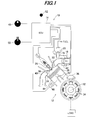
- FIG. 1 is an overall schematic view showing an air/fuel ratio control apparatus for a general-purpose engine according to the embodiment of this invention.
- symbol 10 designates the air/fuel ratio control apparatus for a general-purpose engine 12 (shown in cross-section) 12.
- the apparatus 10 has an Electronic Control Unit (ECU) 14 for electronically controlling the engine 12.
- the ECU 14 comprises a microcomputer having a CPU, memory (EEPROM or non-volatile memory) and other components.
- the engine 12 is a single-cylinder, four-cycle, air-cooled, OHV engine with a displacement of, for example, 440 cc, and is a general-purpose engine to be mounted on a machine such as a generator, lawnmower and snowplow which functions as a load when connected to the engine 12.
- An air intake pipe 16 of the engine 12 is installed with a throttle valve 18 and injector 20. Intake air sucked in and flowing in the air intake pipe 16 is regulated through the throttle valve 18 and fuel injected from the injector 20 are mixed thereto. The thus-generated air-fuel mixture is drawn into a combustion chamber 24 when an intake valve 22 is opened and burned or exploded upon being ignited by a spark plug 26, thereby driving a piston 28.
- the driven piston 28 rotates a crankshaft 32 through a connecting rod 30.
- the crankshaft 32 is connected to the machine (load), and its rotation is transmitted to the load.
- the crankshaft 32 is provided along its circumference with a plurality of (i.e., eight) pulsar coils 34 and when the crankshaft 32 is rotated, a pulsar coil detector 36 installed at a position close to the outer periphery of the pulsar coils 34 produces an output or signal (crank angle signal Pc) indicative of a position of the piston 28.
- the burned air-fuel mixture is discharged to an exhaust pipe 40 when an exhaust valve 38 is opened.
- An electric motor (more precisely, a stepper motor; referred to as "throttle motor") 42 is connected to the throttle valve 18. Specifically, the throttle motor 42 is connected to a rotary shaft of the throttle valve 18 through a speed reducer. The throttle motor 42 is operated to regulate an opening of the throttle valve 18, i.e., a throttle opening.
- the injector 20 is supplied with fuel stored in the fuel tank and pressurized by a fuel supply device including a fuel pump.
- the fuel is mixed fuel containing alcohol (i.e., ethanol) and gasoline.
- a temperature sensor 46 is installed near a cylinder 44 and produces a signal indicating a temperature of the engine 12.
- the aforementioned injector 20, spark plug 26, pulsar coil detector 36, throttle motor 42 and temperature sensor 46 are electrically connected to the ECU 14.
- the ECU 14 is connected with a desired engine speed input knob (switch) 48 to be manipulated by the operator to input a desired speed of the engine 12, a map switching knob (switch) 50 enabled to be manipulated by the operator to switch one from among sets of fuel injection amount maps (mapped data; characteristics) to another, and an indicator 52.
- the indicator 52 comprises a lamp including an LED (Light-Emitting Diode) or the like and located to be visible to the operator.
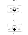
- FIG. 2 is a view showing details of the desired engine speed input knob 48 and FIG. 3 is a view showing details of the map switching knob 50.
- the desired engine speed input knob 48 is made turnable (adjustable) continuously within a scale range between 1000 rpm and 5000 rpm.
- the map switching knob 50 is also made turnable to switch to select one from among maps (sets of characteristics defining the fuel injection amounts) corresponding to low, medium and high alcohol rates.
- the low alcohol rate represents a rate of about 25 %
- the medium alcohol rate a rate of about 50 %
- the high alcohol rate a rate of about 75 %, for instance.
- the knobs 48 and 50 are installed to be pinched with operator's fingers and manipulated by the operator.
- the operator manipulates (turns) the map switching knob 50 to a position corresponding to an assumed (estimated) alcohol rate of the mixed fuel stored in the fuel tank.
- the ECU 14 Based on the detection signals of the pulsar coil detector 36 and temperature sensor 46 and the input signals of the desired engine speed input knob 48 and map switching knob 50, the ECU 14 controls the fuel injection through the injector 20, the ignition timing through the spark plug 26, the throttle opening through the throttle motor 42. Further it controls turning on/off of the indicator 52.
- FIG. 4 is a block diagram showing the operation of the ECU 14 in a functional manner.
- the ECU 14 has an engine speed detection block (engine speed detector), a governor control block (throttle opening regulator), a fuel injection amount calculation block (fuel injection amount calculator), a feedback correction coefficient calculation block and an ignition timing calculation block.
- the engine speed detection block counts a time interval between successive ones of the crank angle signal Pc detected by the pulsar coil detector 36 to detect the engine speed NE (rpm).
- the governor control block is inputted with the desired speed Nd of the engine 12 inputted through the desired engine speed input knob 48 and the engine speed NE detected in the engine speed detection block, and controls the throttle opening such that the detected engine speed NE converges at the desired engine speed Nd.
- the detected engine speed NE when the detected engine speed NE is lower than the desired engine speed Nd, it calculates a throttle opening command value ⁇ th to increase the throttle opening using PID control laws and outputs the same to the throttle motor 42 via the drive circuit (not shown). In contrast, when the engine speed NE is higher than the desired engine speed Nd, it calculates the throttle opening command value ⁇ th to decrease the throttle opening using the PID control laws and outputs the same to the throttle motor 42
- the fuel injection amount calculation block calculates a fuel injection amount Qmap by retrieving one from among three maps (three sets of characteristics) experimentally prepared beforehand for the mixed fuel of the low, medium and high (i.e., 25, 50 and 75 %) alcohol rates by the engine speed NE (detected in the engine speed detection block) and the throttle opening command value ⁇ th (indicative of the engine load outputted from the governor control block).
- the fuel injection amount Qmap is experimentally prepared beforehand under ideal conditions (i.e., ambient temperature: 25°C, altitude: 0 meter, humidity: 50 %).
- the fuel injection amount calculation block is inputted with a signal indicating a position (i.e., designated alcohol rate) from the map switching knob 50 designated by the operator, so that one of the fuel injection amount maps corresponding to the designated position of the map switching knob 50 is selected and the fuel injection amount is calculated by retrieving the selected fuel injection amount map by the aforesaid parameters.
- a position i.e., designated alcohol rate
- the fuel injection amount calculation block is also inputted with the engine temperature Te detected by the temperature sensor 46 and based on the engine temperature Te, corrects the fuel injection amount calculated in accordance with the fuel injection amount map at the engine start.
- the feedback correction coefficient calculation block calculates a feedback correction coefficient K and operates the indicator 52 based on the calculated coefficient K. Specifically, the fuel injection amount Qmap calculated in the fuel injection amount calculation block is forwarded to the feedback correction coefficient calculation block. The feedback correction coefficient calculation block calculates the feedback correction coefficient K in the manner explained later. The feedback correction coefficient K is stored in the memory.
- the calculated coefficient K is sent to the fuel injection amount calculation block, where the fuel injection amount map is corrected or rebuilt by multiplying each fuel injection amount in the map by the coefficient K.
- the fuel injection amount is again calculated in accordance with the corrected fuel injection amount map and the calculation result is outputted to the injector 20 as a final fuel injection amount command value Qf (or the fuel injection amount is simply corrected by the coefficient). Based on the sent value Qf, the injector 20 injects the fuel at the intake port.
- the ignition timing calculation block calculates the ignition timing based on the crank angle signal Pc sent from the pulsar coil detector 36 and outputs the calculated ignition timing to the spark plug 26, via an ignition device (not shown).
- FIG. 5 is a flowchart showing the operation of the ECU 14, i.e., the apparatus 10.
- the illustrated program is executed by the ECU 14 when the operating power to the ECU 14 is being supplied by a starter motor (or recoil starter).
- the program begins in S10, in which it is determined whether the map switching knob 50 was switched, i.e., whether it was changed from a designated position at the last engine stop to another position.
- the program proceeds to S12, in which the feedback correction coefficient K stored in the memory is initialized (explained later). Specifically, the coefficient K is set to 1.0.
- the program proceeds to S14, in which the coefficient K stored in the memory is read to correct or rebuild the fuel injection amount map. Specifically, the fuel injection amount map is corrected by multiplying the map values corresponding to the designated position of the map switching knob 50 by the coefficient K. Then the program proceeds to S16, in which the indicator 52 is turned on.
- the program then proceeds to S18, in which it is determined whether the engine stall has happened. Specifically, when the engine 12 is started by the starter motor (or recoil starter), it is determined whether the engine 12 was stopped without reaching the self-rotational speed.
- the starter motor or recoil starter
- FIG. 6 is a subroutine flowchart showing the process.
- the program begins in S100, it is determined whether the desired engine speed Nd within a predetermined range is inputted, i.e., whether the desired engine speed input knob 48 is set within the range between 1000 rpm and 3000 rpm.
- the program proceeds to S102, in which it is determined whether the detected engine speed NE is equal to or almost equal to the desired engine speed Nd continuously for a predetermined time period, i.e., whether the engine speed NE remains within a range of plus and minus 200 rpm of the desired engine speed Nd consecutively for 5 seconds.
- the program proceeds to S104, in which it is determined whether the throttle opening (precisely, the throttle opening command value ⁇ th) is equal to or less than a predetermined throttle opening and a change amount of the throttle opening (precisely, the change amount of the throttle opening command value ⁇ th) is equal to or less than a predetermined change amount continuously for the predetermined time period.
- the throttle opening is equal to or less than an opening of 30 % (when the full throttle opening is defined as 100 %) and the change amount of the throttle opening remains within a range of plus and minus 1 % for 5 seconds.
- the amount Qmap is calculated based on the engine speed NE and throttle opening command value ⁇ th detected under a condition where the load connected to the engine 12 is constant in accordance with the fuel injection amount map (which is the map whose values have not been corrected in S14). More specifically, the amount Qmap is calculated by retrieving one of the maps by the parameters.
- FIG. 7 is a subroutine flowchart showing the process.
- FIG. 8 is a graph showing the principle.
- the abscissa indicates the air/fuel ratio A/F and a dashed line in the graph represents the output characteristics of the engine 12 relative to the air/fuel ratio A/F.
- the engine output decreases as the air/fuel ratio is changed to the leaner or richer side from the output air/fuel ratio.
- the throttle opening command value ⁇ th is controlled to be constant. Under this condition, if the fuel injection amount is intentionally increased/decreased, i.e., the air/fuel ratio is changed, the engine output is changed accordingly so that the engine speed NE is also changed.
- the throttle opening i.e., command value ⁇ th
- the throttle opening becomes minimum at the point corresponding to the output air/fuel ratio, and increases in the richer or leaner air/fuel ratio direction.
- the minimum value of the throttle value is determined when the fuel injection amount is intentionally increased or decreased, so that the output air/fuel ratio can be estimated.
- the program begins n S200, in which the throttle opening command value ⁇ th is read, while the fuel injection amount is increased.
- the fuel injection amount is increased by 5 % per second, and the throttle opening command value ⁇ th regulated with the increased fuel injection amount is read every 100 milliseconds to calculate an average of the throttle opening command values ⁇ th for 1 second.
- the increased fuel injection amounts (thus injected) and the averages of the throttle opening command values ⁇ th are sequentially stored in the memory.
- the program then proceeds to S202, in which it is determined whether the throttle opening command value ⁇ th is increased by a prescribed value or more, i.e., whether the throttle opening command value ⁇ th (average) since the fuel injection amount increase is increased by 10 % or more compared to that before the fuel injection amount increase. Explaining this in FIG. 8 , it amounts to determining whether the value ⁇ th has reached a point a .
- the program proceeds back to S200.
- the program proceeds to S204, in which the throttle opening command value ⁇ th is read while the fuel injection amount is decreased. This is done by decreasing the fuel injection amount by 5 % per second, and the throttle opening command value ⁇ th regulated with the decreased fuel injection amount is read every 100 milliseconds to calculate an average of the throttle opening command values ⁇ th for 1 second.
- the decreased fuel injection amounts (thus injected) and the averages of the throttle opening command values ⁇ th are sequentially stored in the memory.
- the program then proceeds to S206, in which it is determined whether the throttle opening command value ⁇ th is increased by a prescribed value or more, i.e., whether the throttle opening command value ⁇ th (average) since the fuel injection amount decrease is increased by 5 % or more compared to that before the fuel injection amount decrease. It corresponds to determining whether the value ⁇ th has reached a point b in FIG. 8 . When the result is negative, the program proceeds back to S204.
- the characteristics of the change of the throttle opening command value ⁇ th are approximated as a quadratic curve with the least squares method. Then, the minimum value of the throttle opening command value ⁇ th in the approximated quadratic curve is determined and the fuel injection amount Qmin corresponding to the minimum value of the value ⁇ th is calculated. This fuel injection amount corresponding to the minimum value of the value ⁇ th is the aforesaid fuel injection amount Qmin corresponding to the output air/fuel ratio.
- the program proceeds to S112, in which the feedback correction coefficient K is calculated.
- the coefficient K is calculated based on a ratio of the fuel injection amount Qmap calculated in S108 to the aforesaid fuel injection amount Qmin corresponding to the output air/fuel ratio calculated in S208.
- the coefficient K represents a degree of deviation between the fuel injection amount under the ideal condition (i.e., the condition when the fuel injection amount maps are prepared) and the fuel injection amount corresponding to the output air/fuel ratio in an actual condition where the engine 12 is operated.
- the program proceeds to S24, in which the fuel injection amount map is corrected or rebuilt, i.e., the mapped values are corrected by multiplying by the coefficient K calculated in S112 (or the fuel injection amount retrieved from the map is simply corrected by the coefficient K).
- the program proceeds to S26, in which the indicator 52 is turned on.
- the indicator 52 is turned on for informing the operator of the fact that the fuel injection amount (map) is thus corrected appropriately by the feedback correction using the output air/fuel ratio estimation.
- the program proceeds to S28, in which the coefficient K calculated in S112 is stored in the memory.
- the stored coefficient K will be used for correcting or rebuilding the fuel injection amount (map) at the next engine start as mentioned in S14.
- FIG. 10 is a subroutine flowchart showing the process.
- the program begins in S300, in which it is determined whether the feedback correction coefficient K is equal to or greater than a predetermined value ⁇ .
- the predetermined value ⁇ is set to a value greater than 1.0, e.g., 1.2.
- the program proceeds to S304, in which the indicator 52 is blinked. That is, the affirmative result in S302 means that the coefficient K calculated for the fuel injection amount map corresponding to the high alcohol rate is equal to or greater than 1.2 and in this case, it is estimated that the alcohol rate of the mixed fuel is very high (i.e., 90 % or more). In response to this estimation, the indicator 52 is blinked to prompt the operator to feed gasoline.
- the program proceeds to S308, in which it is estimated that the alcohol rate of the mixed fuel is high.
- the affirmative result in S306 means that the coefficient K calculated for the fuel injection amount map corresponding to the medium alcohol rate is equal to or greater than 1.2, the alcohol rate is estimated to be higher than the medium alcohol rate (i.e., to be 75 % or thereabout). Consequently, the program proceeds to S310, in which the fuel injection amount map is forcibly switched to that for the high alcohol rate.
- the program proceeds to S312, in which it is estimated that the alcohol rate of the mixed fuel is about the medium level. This is because, since the negative result in S306 means that the coefficient K calculated for the fuel injection amount map corresponding to the low alcohol rate is equal to or greater than 1.2, the alcohol rate is estimated to be the medium alcohol rate slightly higher than the low alcohol rate (i.e., to be 50 % or thereabout). Consequently, the program proceeds to S314, in which the fuel injection amount map is forcibly switched to that for the medium alcohol rate.
- the program proceeds to S316, in which it is determined whether the coefficient K is equal to or less than a predetermined value ⁇ .
- the predetermined value ⁇ is set to a value smaller than 1.0, e.g., 0.8.
- the program proceeds to S320, in which it is estimated that the alcohol rate of the mixed fuel is about the medium level. Specifically, since the affirmative result in S318 means that the coefficient K calculated for the fuel injection amount map corresponding to the high alcohol rate is equal to or less than 0.8, the alcohol rate is estimated to be the medium alcohol rate slightly lower than the high alcohol rate (i.e., to be 50 % or thereabout). Consequently, the program proceeds to S322, in which the fuel injection amount map is forcibly switched to that for the medium alcohol rate.
- the program proceeds to S326, in which it is estimated that the alcohol rate of the mixed fuel is low.
- the affirmative result in S324 means that the coefficient K calculated for the fuel injection amount map corresponding to the medium alcohol rate is equal to or less than 0.8, the alcohol rate is estimated to be lower than the medium alcohol rate (i.e., to be 25 % or thereabout). Accordingly, the program proceeds to S328, in which the fuel injection amount map is forcibly switched to that for the low alcohol rate.
- the embodiment is configured to have an apparatus (10) and a method for controlling an air/fuel ratio of a general-purpose internal combustion engine (12) that is connectable to a load, having a desired engine speed input switch (knob 48) adapted for an operator to input a desired speed of the engine (Nd), an engine speed detector (ECU 14) that detects a speed of the engine (NE), a throttle opening regulator (ECU 14; governor control block) that regulates an opening ( ⁇ th) of a throttle valve (18) installed in an air intake pipe (16) of the engine such that the detected engine speed (NE) converges to the inputted desired engine speed (Nd), a fuel injection amount calculator (ECU 14) that calculates a fuel injection amount (Qmap) of the engine based on the detected engine speed (NE) and the regulated throttle opening ( ⁇ th) in accordance with fuel injection amount characteristics, and an injector (20) that injects fuel based on the calculated fuel injection amount, characterized by: a load determiner (ECU 14, S22, S102, S
- the engine control apparatus 10 having the governor control block (throttle opening regulator) which controls the throttle opening such that the engine speed converges to the desired engine speed, it is configured to intentionally increase/decrease the fuel injection amount calculated in accordance with the fuel injection amount characteristics (set beforehand) under the condition where the engine load is kept constant, whereby the engine output, i.e., the engine speed is changed. Based on the throttle opening which is also changed accordingly, the output air/fuel ratio is estimated and the air/fuel ratio used to correct the above fuel injection amount characteristics. With this, it becomes possible to, without using an expensive air/fuel ratio sensor such as the wide-range air/fuel ratio sensor, feedback-control the fuel injection amount such that the engine is operated at the output air/fuel ratio.
- the governor control block throttle opening regulator
- the air/fuel ratio estimator determines a minimum value of the throttle opening regulated when the fuel injection amount is increased/decreased and estimates the (output) air/fuel ratio based on the determined minimum value (ECU 14, S22, S110, S208). With this, it becomes possible to appropriately estimate the output air/fuel ratio with simple structure.
- the fuel injection amount corrector calculates a correction coefficient (K) based on a ratio of the calculated fuel injection amount (Qmap) to a fuel injection amount (Qmin) at which the throttle opening is minimum and corrects the fuel injection amount by the coefficient (ECU 14, S24). With this, it becomes possible to feedback-correct the fuel injection amount without an expensive air/fuel ratio sensor such as the O 2 sensor and wide-range air/fuel ratio sensor.
- the apparatus and method further include: an informing device (LED 52, ECU 14, S26) that informs an operator of a fact that the fuel injection amount is corrected. With this, it becomes possible to inform the operator that the engine is operated appropriately at the output air/fuel ratio.
- LED 52, ECU 14, S26 an informing device
- the apparatus and method further include: a correction coefficient storing unit (ECU 14, S28) that stores the correction coefficient when the fuel injection amount is corrected by the coefficient.
- a correction coefficient storing unit ECU 14, S28
- the load determiner determines that the load connected to the engine is kept constant when the detected engine speed is within a predetermined range set based on the desired engine speed continuously for a predetermined time period (ECU 14, S22, S102). With this, it becomes possible to appropriately determine that the engine load is kept constant, with simple structure.
- the load determiner determines that the load connected to the engine is kept constant when the regulated throttle opening is equal to or less than a predetermined opening and a change amount of the regulated throttle opening is within a predetermined change amount continuously for a predetermined time period (ECU 14, S22, S104).
- the fuel is mixed fuel containing alcohol and gasoline.
- the load comprises at least one of a generator, a lawnmower and a snowplow
- the informing device comprises at least one of a lamp diode (52) and a buzzer.
- the map switching knob 50 has the three positions to be designated, the number may be increased depending on the number of the fuel injection amount maps. Also, the knob 50 may be configured to be continuously changed and in this case, the fuel injection amount between adjacent maps is compensated.
- an audible device such as a buzzer could instead be used.
- a fuel injection amount for mixed fuel determined based on fuel injection amount characteristics is increased/decreased when a load is kept constant and the output air/fuel ratio (at which an output of the engine becomes maximum) is estimated (S200 - S208) and the fuel injection amount is corrected based on the estimated air/fuel ratio, thereby enabling to estimate the output air/fuel ratio without using an expensive air/fuel ratio sensor and to feedback-control the fuel injection amount such that the engine is operated at the output air/fuel ratio.
Landscapes
- Engineering & Computer Science (AREA)
- Chemical & Material Sciences (AREA)
- Combustion & Propulsion (AREA)
- Mechanical Engineering (AREA)
- General Engineering & Computer Science (AREA)
- Oil, Petroleum & Natural Gas (AREA)
- Electrical Control Of Air Or Fuel Supplied To Internal-Combustion Engine (AREA)
- Combined Controls Of Internal Combustion Engines (AREA)
Abstract
Description
- This invention relates to an air/fuel ratio control apparatus for a general-purpose internal combustion engine.
- Conventionally, as one type of air/fuel ratio control of an internal combustion engine, air/fuel ratio feedback control is known which uses an air/fuel ratio sensor installed in an exhaust pipe to detect an air/fuel ratio of exhaust gas and corrects a fuel injection amount such that the detected air/fuel ratio converges to the stoichiometric air/fuel ratio, as taught, for example, in Japanese Laid-Open Patent Application No.
2002-122035 - As to a general-purpose engine to be mounted on a machine such as a generator and lawnmower, it is preferable to operate the engine with a specific air/fuel ratio (so-called the "output air/fuel ratio") that is richer than the stoichiometric air/fuel ratio such that the engine output becomes maximum. Therefore, an O2 sensor (oxygen sensor) whose output changes at the stoichiometric air/fuel ratio or thereabout is not suitable for controlling the engine to operate at the output air/fuel ratio. A wide-range air/fuel ratio sensor that produces an output proportional to the air/fuel ratio enables such the engine control. However, since the wide-range air/fuel sensor is expensive, it is difficult to provide such an air/fuel ratio sensor to a compact and inexpensive general-purpose engine from the cost viewpoint.
- An object of this invention is therefore to overcome the foregoing problem by providing an air/fuel ratio control apparatus for a general-purpose engine that can estimate the output air/fuel ratio without using an expensive air/fuel ratio sensor, and feedback-control the fuel injection amount such that the engine is operated at the output air/fuel ratio.
- In order to achieve the object, this invention provides in its first aspect an apparatus for controlling an air/fuel ratio of a general-purpose internal combustion engine that is connectable to a load, having a desired engine speed input switch adapted for an operator to input a desired speed of the engine, an engine speed detector that detects a speed of the engine, a throttle opening regulator that regulates an opening of a throttle valve installed in an air intake pipe of the engine such that the detected engine speed converges to the inputted desired engine speed, a fuel injection amount calculator that calculates a fuel injection amount of the engine based on the detected engine speed and the regulated throttle opening in accordance with fuel injection amount characteristics, and an injector that injects fuel based on the calculated fuel injection amount, wherein the improvement comprises: a load determiner that determines whether the load connected to the engine is kept constant; a fuel injection amount injecting increasing/decreasing unit that increases/decreases the calculated fuel injection amount to be injected when the load connected to the engine is determined to be kept constant; an air/fuel ratio estimator that estimates an air/fuel ratio at which an output of the engine becomes maximum based on the throttle opening regulated when the fuel injection amount is fuel of the increased/decreased; and a fuel injection amount corrector that corrects the fuel injection amount based on the estimated air/fuel ratio.
- In order to achieve the object, this invention provides in its second aspect a method for controlling an air/fuel ratio of a general-purpose internal combustion engine that is connectable to a load, having a desired engine speed input switch adapted for an operator to input a desired speed of the engine, an engine speed detector that detects a speed of the engine, a throttle opening regulator that regulates an opening of a throttle valve installed in an air intake pipe of the engine such that the detected engine speed converges to the inputted desired engine speed, a fuel injection amount calculator that calculates a fuel injection amount of the engine based on the detected engine speed and the regulated throttle opening in accordance with fuel injection amount characteristics, and an injector that injects fuel based on the calculated fuel injection amount, wherein the improvement comprises the steps of: determining whether the load connected to the engine is kept constant; increasing/decreasing the calculated fuel injection amount to be injected when the load connected to the engine is determined to be kept constant; estimating an air/fuel ratio at which an output of the engine becomes maximum based on the throttle opening regulated when the fuel injection amount is fuel of the increased/decreased; and correcting the fuel injection amount based on the estimated air/fuel ratio.
- The above and other objects and advantages of the invention will be more apparent from the following description and drawings in which:
-
FIG. 1 is an overall schematic view showing an air/fuel ratio control apparatus for a general-purpose engine according to an embodiment of this invention; -
FIG. 2 is a view showing details of a desired engine speed input knob shown inFIG. 1 ; -
FIG. 3 is a view showing details of a map switching knob shown inFIG. 1 ; -
FIG. 4 is a block diagram showing operation of an electronic control unit (ECU) shown inFIG. 1 in a functional manner; -
FIG. 5 is a flowchart showing the operation of the ECU shown inFIG. 4 ; -
FIG. 6 is a subroutine flowchart showing calculation of a feedback correction coefficient referred to in theFIG. 5 flowchart; -
FIG. 7 is a subroutine flowchart showing estimation of an output air/fuel ratio referred to in theFIG. 6 flowchart; -
FIG. 8 is a graph showing a principle of the estimation of the output air/fuel ratio ofFIG. 7 ; -
FIG. 9 is a graph for explaining a fuel injection amount (Qmin) corresponding to the output air/fuel ratio of theFIG. 7 flowchart; and -
FIG. 10 is a subroutine flowchart showing estimation of alcohol rate and forcible switching of fuel injection amount map in response thereto referred to in theFIG. 5 flowchart. - An air/fuel ratio control apparatus for a general-purpose engine according to an embodiment of the present invention will now be explained with reference to the attached drawings.
-
FIG. 1 is an overall schematic view showing an air/fuel ratio control apparatus for a general-purpose engine according to the embodiment of this invention. - In
FIG. 1 ,symbol 10 designates the air/fuel ratio control apparatus for a general-purpose engine 12 (shown in cross-section) 12. Theapparatus 10 has an Electronic Control Unit (ECU) 14 for electronically controlling theengine 12. TheECU 14 comprises a microcomputer having a CPU, memory (EEPROM or non-volatile memory) and other components. - The
engine 12 is a single-cylinder, four-cycle, air-cooled, OHV engine with a displacement of, for example, 440 cc, and is a general-purpose engine to be mounted on a machine such as a generator, lawnmower and snowplow which functions as a load when connected to theengine 12. - An
air intake pipe 16 of theengine 12 is installed with athrottle valve 18 andinjector 20. Intake air sucked in and flowing in theair intake pipe 16 is regulated through thethrottle valve 18 and fuel injected from theinjector 20 are mixed thereto. The thus-generated air-fuel mixture is drawn into acombustion chamber 24 when anintake valve 22 is opened and burned or exploded upon being ignited by aspark plug 26, thereby driving apiston 28. The drivenpiston 28 rotates acrankshaft 32 through a connectingrod 30. Thecrankshaft 32 is connected to the machine (load), and its rotation is transmitted to the load. - The
crankshaft 32 is provided along its circumference with a plurality of (i.e., eight)pulsar coils 34 and when thecrankshaft 32 is rotated, apulsar coil detector 36 installed at a position close to the outer periphery of thepulsar coils 34 produces an output or signal (crank angle signal Pc) indicative of a position of thepiston 28. The burned air-fuel mixture is discharged to anexhaust pipe 40 when anexhaust valve 38 is opened. - An electric motor (more precisely, a stepper motor; referred to as "throttle motor") 42 is connected to the
throttle valve 18. Specifically, thethrottle motor 42 is connected to a rotary shaft of thethrottle valve 18 through a speed reducer. Thethrottle motor 42 is operated to regulate an opening of thethrottle valve 18, i.e., a throttle opening. - The
injector 20 is supplied with fuel stored in the fuel tank and pressurized by a fuel supply device including a fuel pump. The fuel is mixed fuel containing alcohol (i.e., ethanol) and gasoline. - A
temperature sensor 46 is installed near acylinder 44 and produces a signal indicating a temperature of theengine 12. Theaforementioned injector 20,spark plug 26,pulsar coil detector 36,throttle motor 42 andtemperature sensor 46 are electrically connected to theECU 14. - The ECU 14 is connected with a desired engine speed input knob (switch) 48 to be manipulated by the operator to input a desired speed of the
engine 12, a map switching knob (switch) 50 enabled to be manipulated by the operator to switch one from among sets of fuel injection amount maps (mapped data; characteristics) to another, and anindicator 52. Theindicator 52 comprises a lamp including an LED (Light-Emitting Diode) or the like and located to be visible to the operator. -
FIG. 2 is a view showing details of the desired enginespeed input knob 48 andFIG. 3 is a view showing details of themap switching knob 50. - The desired engine
speed input knob 48 is made turnable (adjustable) continuously within a scale range between 1000 rpm and 5000 rpm. Themap switching knob 50 is also made turnable to switch to select one from among maps (sets of characteristics defining the fuel injection amounts) corresponding to low, medium and high alcohol rates. The low alcohol rate represents a rate of about 25 %, the medium alcohol rate a rate of about 50 %, and the high alcohol rate a rate of about 75 %, for instance. - The
knobs map switching knob 50 to a position corresponding to an assumed (estimated) alcohol rate of the mixed fuel stored in the fuel tank. - Based on the detection signals of the
pulsar coil detector 36 andtemperature sensor 46 and the input signals of the desired enginespeed input knob 48 andmap switching knob 50, theECU 14 controls the fuel injection through theinjector 20, the ignition timing through thespark plug 26, the throttle opening through thethrottle motor 42. Further it controls turning on/off of theindicator 52. -
FIG. 4 is a block diagram showing the operation of theECU 14 in a functional manner. As illustrated, the ECU 14 has an engine speed detection block (engine speed detector), a governor control block (throttle opening regulator), a fuel injection amount calculation block (fuel injection amount calculator), a feedback correction coefficient calculation block and an ignition timing calculation block. - The engine speed detection block counts a time interval between successive ones of the crank angle signal Pc detected by the
pulsar coil detector 36 to detect the engine speed NE (rpm). - The governor control block is inputted with the desired speed Nd of the
engine 12 inputted through the desired enginespeed input knob 48 and the engine speed NE detected in the engine speed detection block, and controls the throttle opening such that the detected engine speed NE converges at the desired engine speed Nd. - Specifically, when the detected engine speed NE is lower than the desired engine speed Nd, it calculates a throttle opening command value θth to increase the throttle opening using PID control laws and outputs the same to the
throttle motor 42 via the drive circuit (not shown). In contrast, when the engine speed NE is higher than the desired engine speed Nd, it calculates the throttle opening command value θth to decrease the throttle opening using the PID control laws and outputs the same to thethrottle motor 42 - The fuel injection amount calculation block calculates a fuel injection amount Qmap by retrieving one from among three maps (three sets of characteristics) experimentally prepared beforehand for the mixed fuel of the low, medium and high (i.e., 25, 50 and 75 %) alcohol rates by the engine speed NE (detected in the engine speed detection block) and the throttle opening command value θth (indicative of the engine load outputted from the governor control block). In each of the three maps, the fuel injection amount Qmap is experimentally prepared beforehand under ideal conditions (i.e., ambient temperature: 25°C, altitude: 0 meter, humidity: 50 %).
- The fuel injection amount calculation block is inputted with a signal indicating a position (i.e., designated alcohol rate) from the
map switching knob 50 designated by the operator, so that one of the fuel injection amount maps corresponding to the designated position of themap switching knob 50 is selected and the fuel injection amount is calculated by retrieving the selected fuel injection amount map by the aforesaid parameters. - The fuel injection amount calculation block is also inputted with the engine temperature Te detected by the
temperature sensor 46 and based on the engine temperature Te, corrects the fuel injection amount calculated in accordance with the fuel injection amount map at the engine start. - The feedback correction coefficient calculation block calculates a feedback correction coefficient K and operates the
indicator 52 based on the calculated coefficient K. Specifically, the fuel injection amount Qmap calculated in the fuel injection amount calculation block is forwarded to the feedback correction coefficient calculation block. The feedback correction coefficient calculation block calculates the feedback correction coefficient K in the manner explained later. The feedback correction coefficient K is stored in the memory. - The calculated coefficient K is sent to the fuel injection amount calculation block, where the fuel injection amount map is corrected or rebuilt by multiplying each fuel injection amount in the map by the coefficient K.
- Specifically, the fuel injection amount is again calculated in accordance with the corrected fuel injection amount map and the calculation result is outputted to the
injector 20 as a final fuel injection amount command value Qf (or the fuel injection amount is simply corrected by the coefficient). Based on the sent value Qf, theinjector 20 injects the fuel at the intake port. - The ignition timing calculation block calculates the ignition timing based on the crank angle signal Pc sent from the
pulsar coil detector 36 and outputs the calculated ignition timing to thespark plug 26, via an ignition device (not shown). -
FIG. 5 is a flowchart showing the operation of theECU 14, i.e., theapparatus 10. The illustrated program is executed by theECU 14 when the operating power to theECU 14 is being supplied by a starter motor (or recoil starter). - The program begins in S10, in which it is determined whether the
map switching knob 50 was switched, i.e., whether it was changed from a designated position at the last engine stop to another position. - When the result in S10 is affirmative, the program proceeds to S12, in which the feedback correction coefficient K stored in the memory is initialized (explained later). Specifically, the coefficient K is set to 1.0.
- When the result in S10 is negative, the program proceeds to S14, in which the coefficient K stored in the memory is read to correct or rebuild the fuel injection amount map. Specifically, the fuel injection amount map is corrected by multiplying the map values corresponding to the designated position of the
map switching knob 50 by the coefficient K. Then the program proceeds to S16, in which theindicator 52 is turned on. - The program then proceeds to S18, in which it is determined whether the engine stall has happened. Specifically, when the
engine 12 is started by the starter motor (or recoil starter), it is determined whether theengine 12 was stopped without reaching the self-rotational speed. - When the result in S18 is affirmative, since it means that the fuel injection amount is not appropriate, for example, by the reason that the fuel injection amount corrected by the coefficient K is not appropriate, the program proceeds to S12, in which the coefficient K is initialized. Also the
indicator 52 is turned off. - When the result in S18 is negative, the program proceeds to S20, in which it is confirmed whether the
engine 12 is started and warm-up operation after the engine start has been completed. The determination is made based on the output signal of thetemperature sensor 46. - When it is confirmed that the warm-up operation has been completed, the program proceeds to S22, in which the feedback correction coefficient K is calculated.
-
FIG. 6 is a subroutine flowchart showing the process. - The program begins in S100, it is determined whether the desired engine speed Nd within a predetermined range is inputted, i.e., whether the desired engine
speed input knob 48 is set within the range between 1000 rpm and 3000 rpm. - When the result in S100 is affirmative, the program proceeds to S102, in which it is determined whether the detected engine speed NE is equal to or almost equal to the desired engine speed Nd continuously for a predetermined time period, i.e., whether the engine speed NE remains within a range of plus and minus 200 rpm of the desired engine speed Nd consecutively for 5 seconds.
- When the result in S102 is affirmative, the program proceeds to S104, in which it is determined whether the throttle opening (precisely, the throttle opening command value θth) is equal to or less than a predetermined throttle opening and a change amount of the throttle opening (precisely, the change amount of the throttle opening command value θth) is equal to or less than a predetermined change amount continuously for the predetermined time period.
- To be specific, it is determined whether the throttle opening is equal to or less than an opening of 30 % (when the full throttle opening is defined as 100 %) and the change amount of the throttle opening remains within a range of plus and minus 1 % for 5 seconds.
- When the result in S104 is affirmative, the program proceeds to S106, in which it is determined that the load connected to the
engine 12 is kept constant. - The program next proceeds to S108, in which the fuel injection amount Qmap is calculated. Specifically, the amount Qmap is calculated based on the engine speed NE and throttle opening command value θth detected under a condition where the load connected to the
engine 12 is constant in accordance with the fuel injection amount map (which is the map whose values have not been corrected in S14). More specifically, the amount Qmap is calculated by retrieving one of the maps by the parameters. - Then the program proceeds to S110, in which an output air/fuel ratio is estimated.
-
FIG. 7 is a subroutine flowchart showing the process. - Before explaining this flowchart, a principle of the output air/fuel ratio estimation will be explained first.
-
FIG. 8 is a graph showing the principle. The abscissa indicates the air/fuel ratio A/F and a dashed line in the graph represents the output characteristics of theengine 12 relative to the air/fuel ratio A/F. Generally, the engine output becomes maximum at a specific air/fuel ratio (i.e., the so-called "output air/fuel ratio") on the richer side than the stoichiometric air/fuel ratio (A/F = 14.7). In other words, the engine output decreases as the air/fuel ratio is changed to the leaner or richer side from the output air/fuel ratio. - When the load connected to the
engine 12 is kept constant and the engine speed NE is the same as the desired engine speed Nd, the throttle opening command value θth is controlled to be constant. Under this condition, if the fuel injection amount is intentionally increased/decreased, i.e., the air/fuel ratio is changed, the engine output is changed accordingly so that the engine speed NE is also changed. - Consequently, it also changes the throttle opening command value θth. As illustrated in
FIG. 8 , the throttle opening (i.e., command value θth) becomes minimum at the point corresponding to the output air/fuel ratio, and increases in the richer or leaner air/fuel ratio direction. - Thus, under the condition where the load connected to the
engine 12 is kept constant and the engine speed NE is kept the same as the desired engine speed Nd, the minimum value of the throttle value is determined when the fuel injection amount is intentionally increased or decreased, so that the output air/fuel ratio can be estimated. - The output air/fuel ratio estimation in the
FIG. 7 flowchart is now explained. - The program begins n S200, in which the throttle opening command value θth is read, while the fuel injection amount is increased. Explaining this more concretely, the fuel injection amount is increased by 5 % per second, and the throttle opening command value θth regulated with the increased fuel injection amount is read every 100 milliseconds to calculate an average of the throttle opening command values θth for 1 second. The increased fuel injection amounts (thus injected) and the averages of the throttle opening command values θth are sequentially stored in the memory.
- The program then proceeds to S202, in which it is determined whether the throttle opening command value θth is increased by a prescribed value or more, i.e., whether the throttle opening command value θth (average) since the fuel injection amount increase is increased by 10 % or more compared to that before the fuel injection amount increase. Explaining this in
FIG. 8 , it amounts to determining whether the value θth has reached a point a. When the result in S202 is negative, the program proceeds back to S200. - On the other hand, when the result in S202 is affirmative, the program proceeds to S204, in which the throttle opening command value θth is read while the fuel injection amount is decreased. This is done by decreasing the fuel injection amount by 5 % per second, and the throttle opening command value θth regulated with the decreased fuel injection amount is read every 100 milliseconds to calculate an average of the throttle opening command values θth for 1 second. The decreased fuel injection amounts (thus injected) and the averages of the throttle opening command values θth are sequentially stored in the memory.
- The program then proceeds to S206, in which it is determined whether the throttle opening command value θth is increased by a prescribed value or more, i.e., whether the throttle opening command value θth (average) since the fuel injection amount decrease is increased by 5 % or more compared to that before the fuel injection amount decrease. It corresponds to determining whether the value θth has reached a point b in
FIG. 8 . When the result is negative, the program proceeds back to S204. - When the result in S206 is affirmative, the program proceeds to S208, in which a fuel injection amount Qmin corresponding to the output air/fuel ratio is calculated. To be precise, as shown in
FIG. 9 , the increased/decreased injection amount of injected fuel and the throttle opening command value θth (average) at the time of the fuel injection are plotted. - Next, the characteristics of the change of the throttle opening command value θth are approximated as a quadratic curve with the least squares method. Then, the minimum value of the throttle opening command value θth in the approximated quadratic curve is determined and the fuel injection amount Qmin corresponding to the minimum value of the value θth is calculated. This fuel injection amount corresponding to the minimum value of the value θth is the aforesaid fuel injection amount Qmin corresponding to the output air/fuel ratio.
- Returning to the explanation on the
FIG. 6 flowchart, the program proceeds to S112, in which the feedback correction coefficient K is calculated. As shown in the drawing, the coefficient K is calculated based on a ratio of the fuel injection amount Qmap calculated in S108 to the aforesaid fuel injection amount Qmin corresponding to the output air/fuel ratio calculated in S208. - In other words, the coefficient K represents a degree of deviation between the fuel injection amount under the ideal condition (i.e., the condition when the fuel injection amount maps are prepared) and the fuel injection amount corresponding to the output air/fuel ratio in an actual condition where the
engine 12 is operated. - Returning to the explanation on the
FIG. 5 flowchart, the program proceeds to S24, in which the fuel injection amount map is corrected or rebuilt, i.e., the mapped values are corrected by multiplying by the coefficient K calculated in S112 (or the fuel injection amount retrieved from the map is simply corrected by the coefficient K). - The program proceeds to S26, in which the
indicator 52 is turned on. Theindicator 52 is turned on for informing the operator of the fact that the fuel injection amount (map) is thus corrected appropriately by the feedback correction using the output air/fuel ratio estimation. - The program proceeds to S28, in which the coefficient K calculated in S112 is stored in the memory. The stored coefficient K will be used for correcting or rebuilding the fuel injection amount (map) at the next engine start as mentioned in S14.
- Then the program proceeds to S30, in which the alcohol rate estimation and fuel injection amount map forcible switching is conducted.
-
FIG. 10 is a subroutine flowchart showing the process. - The program begins in S300, in which it is determined whether the feedback correction coefficient K is equal to or greater than a predetermined value α. The predetermined value α is set to a value greater than 1.0, e.g., 1.2.
- When the result in S300 is affirmative, the program proceeds to S302, in which it is determined whether the
map switching knob 50 is at a position of the high alcohol rate. - When the result in S302 is affirmative, the program proceeds to S304, in which the
indicator 52 is blinked. That is, the affirmative result in S302 means that the coefficient K calculated for the fuel injection amount map corresponding to the high alcohol rate is equal to or greater than 1.2 and in this case, it is estimated that the alcohol rate of the mixed fuel is very high (i.e., 90 % or more). In response to this estimation, theindicator 52 is blinked to prompt the operator to feed gasoline. - When the result in S302 is negative, the program proceeds to S306, in which it is determined whether the
map switching knob 50 is at a position of the medium alcohol rate. - When the result in S306 is affirmative, the program proceeds to S308, in which it is estimated that the alcohol rate of the mixed fuel is high. The reason is that, since the affirmative result in S306 means that the coefficient K calculated for the fuel injection amount map corresponding to the medium alcohol rate is equal to or greater than 1.2, the alcohol rate is estimated to be higher than the medium alcohol rate (i.e., to be 75 % or thereabout). Consequently, the program proceeds to S310, in which the fuel injection amount map is forcibly switched to that for the high alcohol rate.
- When the result in S306 is negative, the program proceeds to S312, in which it is estimated that the alcohol rate of the mixed fuel is about the medium level. This is because, since the negative result in S306 means that the coefficient K calculated for the fuel injection amount map corresponding to the low alcohol rate is equal to or greater than 1.2, the alcohol rate is estimated to be the medium alcohol rate slightly higher than the low alcohol rate (i.e., to be 50 % or thereabout). Consequently, the program proceeds to S314, in which the fuel injection amount map is forcibly switched to that for the medium alcohol rate.
- When the result in S300 is negative, the program proceeds to S316, in which it is determined whether the coefficient K is equal to or less than a predetermined value β. The predetermined value β is set to a value smaller than 1.0, e.g., 0.8.
- When the result in S316 is affirmative, the program proceeds to S318, in which it is determined whether the
map switching knob 50 is at a position of the high alcohol rate. - When the result in S318 is affirmative, the program proceeds to S320, in which it is estimated that the alcohol rate of the mixed fuel is about the medium level. Specifically, since the affirmative result in S318 means that the coefficient K calculated for the fuel injection amount map corresponding to the high alcohol rate is equal to or less than 0.8, the alcohol rate is estimated to be the medium alcohol rate slightly lower than the high alcohol rate (i.e., to be 50 % or thereabout). Consequently, the program proceeds to S322, in which the fuel injection amount map is forcibly switched to that for the medium alcohol rate.
- When the result in S318 is negative, the program proceeds to S324, in which it is determined whether the
map switching knob 50 is at a position of the medium alcohol rate. - When the result in S324 is affirmative, the program proceeds to S326, in which it is estimated that the alcohol rate of the mixed fuel is low. Explaining this, since the affirmative result in S324 means that the coefficient K calculated for the fuel injection amount map corresponding to the medium alcohol rate is equal to or less than 0.8, the alcohol rate is estimated to be lower than the medium alcohol rate (i.e., to be 25 % or thereabout). Accordingly, the program proceeds to S328, in which the fuel injection amount map is forcibly switched to that for the low alcohol rate.
- When the result in S316 or S324 is negative, the program is terminated without forcibly switching the fuel injection amount map.
- As stated above, the embodiment is configured to have an apparatus (10) and a method for controlling an air/fuel ratio of a general-purpose internal combustion engine (12) that is connectable to a load, having a desired engine speed input switch (knob 48) adapted for an operator to input a desired speed of the engine (Nd), an engine speed detector (ECU 14) that detects a speed of the engine (NE), a throttle opening regulator (ECU 14; governor control block) that regulates an opening (θth) of a throttle valve (18) installed in an air intake pipe (16) of the engine such that the detected engine speed (NE) converges to the inputted desired engine speed (Nd), a fuel injection amount calculator (ECU 14) that calculates a fuel injection amount (Qmap) of the engine based on the detected engine speed (NE) and the regulated throttle opening (θth) in accordance with fuel injection amount characteristics, and an injector (20) that injects fuel based on the calculated fuel injection amount, characterized by: a load determiner (ECU 14, S22, S102, S104) that determines whether the load connected to the engine is kept constant; a fuel injection amount injecting increasing/decreasing unit (ECU 14, S22, S110, S200 - S204) that increases/decreases the calculated fuel injection amount (Qmap) to be injected when the load connected to the engine is determined to be kept constant; an air/fuel ratio estimator (ECU 14, S22, S110, S208) that estimates an (output) air/fuel ratio (Qmin) at which an output of the engine becomes maximum based on the throttle opening regulated when the fuel injection amount is fuel of the increased/decreased; and a fuel injection amount corrector (ECU 14, S24) that corrects the fuel injection amount based on the estimated air/fuel ratio.
- Specifically, in the
engine control apparatus 10 having the governor control block (throttle opening regulator) which controls the throttle opening such that the engine speed converges to the desired engine speed, it is configured to intentionally increase/decrease the fuel injection amount calculated in accordance with the fuel injection amount characteristics (set beforehand) under the condition where the engine load is kept constant, whereby the engine output, i.e., the engine speed is changed. Based on the throttle opening which is also changed accordingly, the output air/fuel ratio is estimated and the air/fuel ratio used to correct the above fuel injection amount characteristics. With this, it becomes possible to, without using an expensive air/fuel ratio sensor such as the wide-range air/fuel ratio sensor, feedback-control the fuel injection amount such that the engine is operated at the output air/fuel ratio. - In the apparatus and method, the air/fuel ratio estimator determines a minimum value of the throttle opening regulated when the fuel injection amount is increased/decreased and estimates the (output) air/fuel ratio based on the determined minimum value (
ECU 14, S22, S110, S208). With this, it becomes possible to appropriately estimate the output air/fuel ratio with simple structure. - In the apparatus and method, the fuel injection amount corrector calculates a correction coefficient (K) based on a ratio of the calculated fuel injection amount (Qmap) to a fuel injection amount (Qmin) at which the throttle opening is minimum and corrects the fuel injection amount by the coefficient (
ECU 14, S24). With this, it becomes possible to feedback-correct the fuel injection amount without an expensive air/fuel ratio sensor such as the O2 sensor and wide-range air/fuel ratio sensor. - The apparatus and method further include: an informing device (
LED 52,ECU 14, S26) that informs an operator of a fact that the fuel injection amount is corrected. With this, it becomes possible to inform the operator that the engine is operated appropriately at the output air/fuel ratio. - The apparatus and method further include: a correction coefficient storing unit (
ECU 14, S28) that stores the correction coefficient when the fuel injection amount is corrected by the coefficient. - With this, at the next engine start, since the fuel injection amount is corrected or is calculated in accordance with the fuel injection amount characteristics corrected or rebuilt with the stored correction coefficient, the engine can be appropriately started.
- In the apparatus and method, the load determiner determines that the load connected to the engine is kept constant when the detected engine speed is within a predetermined range set based on the desired engine speed continuously for a predetermined time period (
ECU 14, S22, S102). With this, it becomes possible to appropriately determine that the engine load is kept constant, with simple structure. - In the apparatus and method, the load determiner determines that the load connected to the engine is kept constant when the regulated throttle opening is equal to or less than a predetermined opening and a change amount of the regulated throttle opening is within a predetermined change amount continuously for a predetermined time period (
ECU 14, S22, S104). - Specifically, when the engine is operated at the idling speed continuously for a predetermined time period, it is determined that the engine load is kept constant. With this, it becomes possible to appropriately determine that the engine load is kept constant, with simple structure.
- In the apparatus and method, the fuel is mixed fuel containing alcohol and gasoline. With this, when the output air/fuel ratio changes depending on a mixture rate of alcohol to gasoline, since the output air/fuel ratio can be accurately estimated, the engine can be appropriately operated at the output air/fuel ratio regardless of the mixture rate.
- In the apparatus and method, the load comprises at least one of a generator, a lawnmower and a snowplow, and the informing device comprises at least one of a lamp diode (52) and a buzzer.
- It should be noted that, although, in response to the affirmative results in both S102 and S104, the engine load is determined to be kept constant, the determination may be made when the result of either S102 or S104 is affirmative.
- It should also be noted that, although the
map switching knob 50 has the three positions to be designated, the number may be increased depending on the number of the fuel injection amount maps. Also, theknob 50 may be configured to be continuously changed and in this case, the fuel injection amount between adjacent maps is compensated. - It should further be noted that, although the operator is informed visually by lighting the
indicator 52 or the like, an audible device such as a buzzer could instead be used. - In an apparatus for controlling an air/fuel ratio of a general-purpose internal combustion engine using mixed fuel containing alcohol and gasoline and operated at a desired engine speed inputted by the operator while a throttle opening is regulated such that a detected engine speed converges to the inputted desired engine speed, a fuel injection amount for mixed fuel determined based on fuel injection amount characteristics is increased/decreased when a load is kept constant and the output air/fuel ratio (at which an output of the engine becomes maximum) is estimated (S200 - S208) and the fuel injection amount is corrected based on the estimated air/fuel ratio, thereby enabling to estimate the output air/fuel ratio without using an expensive air/fuel ratio sensor and to feedback-control the fuel injection amount such that the engine is operated at the output air/fuel ratio.
Claims (16)
- An apparatus (10) for controlling an air/fuel ratio of a general-purpose internal combustion engine (12) that is connectable to a load, having a desired engine speed input switch (48) adapted for an operator to input a desired speed of the engine (Nd), an engine speed detector (14) that detects a speed of the engine (NE), a throttle opening regulator (14) that regulates an opening (θth) of a throttle valve (18) installed in an air intake pipe (16) of the engine such that the detected engine speed (NE) converges to the inputted desired engine speed (Nd), a fuel injection amount calculator (14) that calculates a fuel injection amount (Qmap) of the engine based on the detected engine speed (NE) and the regulated throttle opening (θth) in accordance with fuel injection amount characteristics, and an injector (20) that injects fuel based on the calculated fuel injection amount,
characterized by:a load determiner (14, S22, S102, S104) that determines whether the load connected to the engine is kept constant;a fuel injection amount injecting increasing/decreasing unit (14, S22, S110, S200 - S204) that increases/decreases the calculated fuel injection amount (Qmap) to be injected when the load connected to the engine is determined to be kept constant;an air/fuel ratio estimator (14, S22, S110, S208) that estimates an air/fuel ratio (Qmin) at which an output of the engine becomes maximum based on the throttle opening regulated when the fuel injection amount is fuel of the increased/decreased; anda fuel injection amount corrector (14, S24) that corrects the fuel injection amount based on the estimated air/fuel ratio. - The apparatus according to claim 1, wherein the air/fuel ratio estimator determines a minimum value of the throttle opening regulated when the fuel injection amount is increased/decreased and estimates the air/fuel ratio based on the determined minimum value (14, S22, S110, S208).
- The apparatus according to claim 1 or 2, wherein the fuel injection amount corrector calculates a correction coefficient (K) based on a ratio of the calculated fuel injection amount (Qmap) to a fuel injection amount (Qmin) at which the throttle opening is minimum and corrects the fuel injection amount by the coefficient (14,S24).
- The apparatus according to any of claims 1 to 3, further including:an informing device (52, 14, S26) that informs an operator of a fact that the fuel injection amount is corrected.
- The apparatus according to claim 3 or 4, further including:a correction coefficient storing unit (14, S28) that stores the correction coefficient when the fuel injection amount is corrected by the coefficient.
- The apparatus according to any of claims 1 to 5, wherein the load determiner determines that the load connected to the engine is kept constant when the detected engine speed is within a predetermined range set based on the desired engine speed continuously for a predetermined time period (14, S22, S102).
- The apparatus according to any of claims 1 to 6, wherein the load determiner determines that the load connected to the engine is kept constant when the regulated throttle opening is equal to or less than a predetermined opening and a change amount of the regulated throttle opening is within a predetermined change amount continuously for a predetermined time period (14, S22, S104).
- The apparatus according to any of claims 1 to 7, wherein the fuel is mixed fuel containing alcohol and gasoline.
- A method for controlling an air/fuel ratio of a general-purpose internal combustion engine (12) that is connectable to a load, having a desired engine speed input switch (48) adapted for an operator to input a desired speed of the engine (Nd), an engine speed detector (14) that detects a speed of the engine (NE), a throttle opening regulator (14) that regulates an opening (θth) of a throttle valve (18) installed in an air intake pipe (16) of the engine such that the detected engine speed (NE) converges to the inputted desired engine speed (Nd), a fuel injection amount calculator (14) that calculates a fuel injection amount (Qmap) of the engine based on the detected engine speed (NE) and the regulated throttle opening (θth) in accordance with fuel injection amount characteristics, and an injector (20) that injects fuel based on the calculated fuel injection amount,
characterized by the steps of:determining whether the load connected to the engine is kept constant (14, S22,S102,S104);increasing/decreasing the calculated fuel injection amount (Qmap) to be injected when the load connected to the engine is determined to be kept constant (14, S22, S110, S200 - S204);estimating an air/fuel ratio (Qmin) at which an output of the engine becomes maximum based on the throttle opening regulated when the fuel injection amount is fuel of the increased/decreased (14, S22, S110, S208); andcorrecting the fuel injection amount based on the estimated air/fuel ratio (14, S30, S310, S314, S322, S328). - The method according to claim 9, wherein the step of air/fuel ratio estimating determines a minimum value of the throttle opening regulated when the fuel injection amount is increased/decreased and estimates the air/fuel ratio based on the determined minimum value (14, S22, S110, S208).
- The method according to claim 9 or 10, wherein the step of fuel injection amount correcting calculates a correction coefficient (K) based on a ratio of the calculated fuel injection amount (Qmap) to a fuel injection amount (Qmin) at which the throttle opening is minimum and corrects the fuel injection amount by the coefficient (14, S24).
- The method according to any of claims 9 to 11, further including the step of:informing an operator of a fact that the fuel injection amount is corrected (52, 14, S26).
- The method according to claim 11 or 12, further including the step of:storing the correction coefficient when the fuel injection amount is corrected by the coefficient (14, S28).
- The method according to any of claims 9 to 13, wherein the step of load determining determines that the load connected to the engine is kept constant when the detected engine speed is within a predetermined range set based on the desired engine speed continuously for a predetermined time period (14, S22, S102).
- The method according to any of claims 9 to 14, wherein the step of load determining determines that the load connected to the engine is kept constant when the regulated throttle opening is equal to or less than a predetermined opening and a change amount of the regulated throttle opening is within a predetermined change amount continuously for a predetermined time period (14, S22, S104).
- The method according to any of claims 9 to 15, wherein the fuel is mixed fuel containing alcohol and gasoline.
Applications Claiming Priority (1)
| Application Number | Priority Date | Filing Date | Title |
|---|---|---|---|
| JP2010029033A JP5443195B2 (en) | 2010-02-12 | 2010-02-12 | General-purpose engine air-fuel ratio control device |
Publications (2)
| Publication Number | Publication Date |
|---|---|
| EP2357343A1 true EP2357343A1 (en) | 2011-08-17 |
| EP2357343B1 EP2357343B1 (en) | 2013-02-20 |
Family
ID=43799436
Family Applications (1)
| Application Number | Title | Priority Date | Filing Date |
|---|---|---|---|
| EP11151123A Not-in-force EP2357343B1 (en) | 2010-02-12 | 2011-01-17 | Air/Fuel ratio control apparatus for general-purpose engine |
Country Status (5)
| Country | Link |
|---|---|
| US (1) | US9541011B2 (en) |
| EP (1) | EP2357343B1 (en) |
| JP (1) | JP5443195B2 (en) |
| CN (1) | CN102155316B (en) |
| BR (1) | BRPI1100816A2 (en) |
Cited By (1)
| Publication number | Priority date | Publication date | Assignee | Title |
|---|---|---|---|---|
| GB2605226A (en) * | 2021-10-24 | 2022-09-28 | Hardenbrook Whiteley Paul | Potentiometer adjustable car fuel ECU |
Families Citing this family (1)
| Publication number | Priority date | Publication date | Assignee | Title |
|---|---|---|---|---|
| JP5346838B2 (en) * | 2010-02-12 | 2013-11-20 | 本田技研工業株式会社 | General-purpose engine air-fuel ratio control device |
Citations (5)
| Publication number | Priority date | Publication date | Assignee | Title |
|---|---|---|---|---|
| US5586537A (en) * | 1994-02-28 | 1996-12-24 | Unisia Jecs Corporation | Fuel property detecting apparatus for internal combustion engines |
| US5832896A (en) * | 1995-09-18 | 1998-11-10 | Zenith Fuel Systems, Inc. | Governor and control system for internal combustion engines |
| US5915368A (en) * | 1996-05-28 | 1999-06-29 | Matsushita Electric Industrial Co, Ltd | Air/fuel ratio control apparatus that uses a neural network |
| EP1108871A1 (en) * | 1999-12-17 | 2001-06-20 | MAGNETI MARELLI S.p.A. | A method for estimating the stoichiometric ratio for a control system of an internal combustion engine |
| JP2002122035A (en) | 2000-10-17 | 2002-04-26 | Toyota Motor Corp | Air-fuel ratio control device for internal combustion engine |
Family Cites Families (30)
| Publication number | Priority date | Publication date | Assignee | Title |
|---|---|---|---|---|
| US1409736A (en) * | 1919-08-08 | 1922-03-14 | Gen Motors Corp | Power plant |
| JPS6053647A (en) * | 1983-09-05 | 1985-03-27 | Japan Electronic Control Syst Co Ltd | Learning control system at starting of electronic control fuel injection system internal-combustion engine |
| JPS60224945A (en) * | 1984-04-24 | 1985-11-09 | Nissan Motor Co Ltd | Air/fuel ratio controller |
| JPS62182045A (en) * | 1986-02-04 | 1987-08-10 | 三信工業株式会社 | Corrosion-proof device for fuel tank |
| US5255655A (en) * | 1989-06-15 | 1993-10-26 | Robert Bosch Gmbh | Fuel injection system for an internal combustion engine |
| JPH0741880Y2 (en) * | 1989-12-28 | 1995-09-27 | マツダ株式会社 | Combustion control device for gas engine |
| US5101788A (en) * | 1990-04-26 | 1992-04-07 | Mitsubishi Denki K.K. | Internal-combustion engine control device |
| JP2884472B2 (en) * | 1994-03-23 | 1999-04-19 | 株式会社ユニシアジェックス | Fuel property detection device for internal combustion engine |
| JP3784080B2 (en) * | 1994-06-16 | 2006-06-07 | 株式会社デンソー | Fuel injection amount correction method during warm-up process |
| JPH08114158A (en) * | 1994-10-17 | 1996-05-07 | Nippondenso Co Ltd | Exhaust gas reflux valve control device |
| US5553580A (en) * | 1995-01-13 | 1996-09-10 | Ganoung; David P. | Stratified charge engines and method for their operation |
| JPH08261039A (en) * | 1995-03-24 | 1996-10-08 | Unisia Jecs Corp | Air-fuel ratio controller for engine with evaporative fuel processor |
| JP3622290B2 (en) * | 1995-10-02 | 2005-02-23 | 日産自動車株式会社 | Control device for internal combustion engine |
| JPH09209795A (en) * | 1996-01-31 | 1997-08-12 | Suzuki Motor Corp | Fuel injection control device for outboard motor |
| JPH09303180A (en) * | 1996-05-10 | 1997-11-25 | Hitachi Ltd | Engine control method |
| JP2000018065A (en) * | 1998-06-30 | 2000-01-18 | Yanmar Diesel Engine Co Ltd | Control method for internal combustion engine |
| US6880524B2 (en) * | 2002-04-15 | 2005-04-19 | Ford Global Technologies, Llc | Diesel EGR control |
| US20040000275A1 (en) * | 2002-05-01 | 2004-01-01 | Mcintyre Michael Gene | Multi map fuel detection fuel injection |
| DE10360129A1 (en) * | 2003-12-20 | 2005-07-21 | Daimlerchrysler Ag | Driving assistance device, vehicle and method for driving speed control of a vehicle |
| JP4251109B2 (en) * | 2004-04-27 | 2009-04-08 | トヨタ自動車株式会社 | Fuel injection control device for internal combustion engine |
| US7225787B2 (en) * | 2004-11-18 | 2007-06-05 | Massachusetts Institute Of Technology | Optimized fuel management system for direct injection ethanol enhancement of gasoline engines |
| US7581516B2 (en) * | 2005-11-18 | 2009-09-01 | Matthew Snow | Water/alcohol injection flow switch safety device |
| WO2008012626A2 (en) * | 2006-07-20 | 2008-01-31 | Toyota Jidosha Kabushiki Kaisha | Control apparatus and control method for direct injection spark ignition internal combustion engine |
| JP2008051063A (en) * | 2006-08-28 | 2008-03-06 | Toyota Motor Corp | Control device for internal combustion engine |
| JP5095973B2 (en) * | 2006-09-25 | 2012-12-12 | 本田技研工業株式会社 | Fuel injection control device for various types of fuel engines |
| JP4462283B2 (en) * | 2007-03-14 | 2010-05-12 | 日産自動車株式会社 | ENGINE LOAD ESTIMATION DEVICE AND ENGINE LOAD ESTIMATION METHOD |
| DE102007021283A1 (en) * | 2007-05-07 | 2008-11-13 | Continental Automotive Gmbh | Method and device for determining the combustion lambda value of an internal combustion engine |
| US7690336B2 (en) * | 2008-02-29 | 2010-04-06 | General Electric Company | Adaptive miller cycle engine |
| JP4561906B2 (en) * | 2008-08-21 | 2010-10-13 | トヨタ自動車株式会社 | Fuel supply device for flexible fuel internal combustion engine |
| JP4717108B2 (en) * | 2008-11-17 | 2011-07-06 | 三菱電機株式会社 | Control device for internal combustion engine |
-
2010
- 2010-02-12 JP JP2010029033A patent/JP5443195B2/en not_active Expired - Fee Related
- 2010-12-27 US US12/978,744 patent/US9541011B2/en active Active
-
2011
- 2011-01-17 EP EP11151123A patent/EP2357343B1/en not_active Not-in-force
- 2011-01-20 CN CN2011100231905A patent/CN102155316B/en not_active Expired - Fee Related
- 2011-02-11 BR BRPI1100816-4A patent/BRPI1100816A2/en not_active Application Discontinuation
Patent Citations (5)
| Publication number | Priority date | Publication date | Assignee | Title |
|---|---|---|---|---|
| US5586537A (en) * | 1994-02-28 | 1996-12-24 | Unisia Jecs Corporation | Fuel property detecting apparatus for internal combustion engines |
| US5832896A (en) * | 1995-09-18 | 1998-11-10 | Zenith Fuel Systems, Inc. | Governor and control system for internal combustion engines |
| US5915368A (en) * | 1996-05-28 | 1999-06-29 | Matsushita Electric Industrial Co, Ltd | Air/fuel ratio control apparatus that uses a neural network |
| EP1108871A1 (en) * | 1999-12-17 | 2001-06-20 | MAGNETI MARELLI S.p.A. | A method for estimating the stoichiometric ratio for a control system of an internal combustion engine |
| JP2002122035A (en) | 2000-10-17 | 2002-04-26 | Toyota Motor Corp | Air-fuel ratio control device for internal combustion engine |
Cited By (2)
| Publication number | Priority date | Publication date | Assignee | Title |
|---|---|---|---|---|
| GB2605226A (en) * | 2021-10-24 | 2022-09-28 | Hardenbrook Whiteley Paul | Potentiometer adjustable car fuel ECU |
| GB2605226B (en) * | 2021-10-24 | 2023-05-03 | Hardenbrook Whiteley Paul | Potentiometer adjustable car fuel ECU |
Also Published As
| Publication number | Publication date |
|---|---|
| US9541011B2 (en) | 2017-01-10 |
| US20110202257A1 (en) | 2011-08-18 |
| JP5443195B2 (en) | 2014-03-19 |
| EP2357343B1 (en) | 2013-02-20 |
| CN102155316A (en) | 2011-08-17 |
| CN102155316B (en) | 2013-12-11 |
| JP2011163279A (en) | 2011-08-25 |
| BRPI1100816A2 (en) | 2012-07-31 |
Similar Documents
| Publication | Publication Date | Title |
|---|---|---|
| EP2357344B1 (en) | Air/Fuel ratio control apparatus for general-purpose engine | |
| EP2360364B1 (en) | Air/Fuel ratio control apparatus for general-purpose engine | |
| US9115670B2 (en) | Fuel control method for hand-carried engine-driven working machine | |
| US8838361B2 (en) | Control apparatus for general-purpose engine | |
| US5852998A (en) | Fuel-injection control device for outboard motors | |
| EP2538058A1 (en) | Idle rotation speed control device for bifuel engine | |
| EP2357343B1 (en) | Air/Fuel ratio control apparatus for general-purpose engine | |
| JP5427727B2 (en) | Engine control system | |
| US8037875B2 (en) | Control apparatus and control method for internal combustion engine | |
| US8770172B2 (en) | Fuel shortage detecting apparatus for general-purpose engine | |
| US6817339B2 (en) | Engine control device | |
| JP5369070B2 (en) | Fuel outage judgment device for general-purpose engines | |
| JP2016098760A (en) | Electronic control device | |
| US20120059570A1 (en) | Warm-up control apparatus for general-purpose engine | |
| JP2846023B2 (en) | Electronically controlled fuel injection device for internal combustion engine | |
| JP2012057534A (en) | Control device for general-purpose engine | |
| JPH05256176A (en) | Injection timing control device for diesel engine |
Legal Events
| Date | Code | Title | Description |
|---|---|---|---|
| PUAI | Public reference made under article 153(3) epc to a published international application that has entered the european phase |
Free format text: ORIGINAL CODE: 0009012 |
|
| 17P | Request for examination filed |
Effective date: 20110117 |
|
| AK | Designated contracting states |
Kind code of ref document: A1 Designated state(s): AL AT BE BG CH CY CZ DE DK EE ES FI FR GB GR HR HU IE IS IT LI LT LU LV MC MK MT NL NO PL PT RO RS SE SI SK SM TR |
|
| AX | Request for extension of the european patent |
Extension state: BA ME |
|
| RIC1 | Information provided on ipc code assigned before grant |
Ipc: F02D 41/06 20060101ALI20120829BHEP Ipc: F02D 35/00 20060101AFI20120829BHEP Ipc: F02D 41/00 20060101ALI20120829BHEP Ipc: F02D 19/08 20060101ALI20120829BHEP |
|
| GRAP | Despatch of communication of intention to grant a patent |
Free format text: ORIGINAL CODE: EPIDOSNIGR1 |
|
| RIN1 | Information on inventor provided before grant (corrected) |
Inventor name: FUKUSHIMA, TOMOKI Inventor name: HASHIZUME, TAKASHI Inventor name: SAITO, SHIGERU |
|
| GRAS | Grant fee paid |
Free format text: ORIGINAL CODE: EPIDOSNIGR3 |
|
| GRAA | (expected) grant |
Free format text: ORIGINAL CODE: 0009210 |
|
| AK | Designated contracting states |
Kind code of ref document: B1 Designated state(s): AL AT BE BG CH CY CZ DE DK EE ES FI FR GB GR HR HU IE IS IT LI LT LU LV MC MK MT NL NO PL PT RO RS SE SI SK SM TR |
|
| REG | Reference to a national code |
Ref country code: GB Ref legal event code: FG4D |
|
| REG | Reference to a national code |
Ref country code: CH Ref legal event code: EP |
|
| REG | Reference to a national code |
Ref country code: AT Ref legal event code: REF Ref document number: 597668 Country of ref document: AT Kind code of ref document: T Effective date: 20130315 |
|
| REG | Reference to a national code |
Ref country code: IE Ref legal event code: FG4D |
|
| REG | Reference to a national code |
Ref country code: DE Ref legal event code: R096 Ref document number: 602011000905 Country of ref document: DE Effective date: 20130418 |
|
| REG | Reference to a national code |
Ref country code: AT Ref legal event code: MK05 Ref document number: 597668 Country of ref document: AT Kind code of ref document: T Effective date: 20130220 |
|
| REG | Reference to a national code |
Ref country code: NL Ref legal event code: VDEP Effective date: 20130220 |
|
| REG | Reference to a national code |
Ref country code: LT Ref legal event code: MG4D |
|
| PG25 | Lapsed in a contracting state [announced via postgrant information from national office to epo] |
Ref country code: AT Free format text: LAPSE BECAUSE OF FAILURE TO SUBMIT A TRANSLATION OF THE DESCRIPTION OR TO PAY THE FEE WITHIN THE PRESCRIBED TIME-LIMIT Effective date: 20130220 Ref country code: LT Free format text: LAPSE BECAUSE OF FAILURE TO SUBMIT A TRANSLATION OF THE DESCRIPTION OR TO PAY THE FEE WITHIN THE PRESCRIBED TIME-LIMIT Effective date: 20130220 Ref country code: BG Free format text: LAPSE BECAUSE OF FAILURE TO SUBMIT A TRANSLATION OF THE DESCRIPTION OR TO PAY THE FEE WITHIN THE PRESCRIBED TIME-LIMIT Effective date: 20130520 Ref country code: IS Free format text: LAPSE BECAUSE OF FAILURE TO SUBMIT A TRANSLATION OF THE DESCRIPTION OR TO PAY THE FEE WITHIN THE PRESCRIBED TIME-LIMIT Effective date: 20130620 Ref country code: SE Free format text: LAPSE BECAUSE OF FAILURE TO SUBMIT A TRANSLATION OF THE DESCRIPTION OR TO PAY THE FEE WITHIN THE PRESCRIBED TIME-LIMIT Effective date: 20130220 Ref country code: NO Free format text: LAPSE BECAUSE OF FAILURE TO SUBMIT A TRANSLATION OF THE DESCRIPTION OR TO PAY THE FEE WITHIN THE PRESCRIBED TIME-LIMIT Effective date: 20130520 Ref country code: ES Free format text: LAPSE BECAUSE OF FAILURE TO SUBMIT A TRANSLATION OF THE DESCRIPTION OR TO PAY THE FEE WITHIN THE PRESCRIBED TIME-LIMIT Effective date: 20130531 |
|
| PG25 | Lapsed in a contracting state [announced via postgrant information from national office to epo] |
Ref country code: PT Free format text: LAPSE BECAUSE OF FAILURE TO SUBMIT A TRANSLATION OF THE DESCRIPTION OR TO PAY THE FEE WITHIN THE PRESCRIBED TIME-LIMIT Effective date: 20130620 Ref country code: SI Free format text: LAPSE BECAUSE OF FAILURE TO SUBMIT A TRANSLATION OF THE DESCRIPTION OR TO PAY THE FEE WITHIN THE PRESCRIBED TIME-LIMIT Effective date: 20130220 Ref country code: GR Free format text: LAPSE BECAUSE OF FAILURE TO SUBMIT A TRANSLATION OF THE DESCRIPTION OR TO PAY THE FEE WITHIN THE PRESCRIBED TIME-LIMIT Effective date: 20130521 Ref country code: FI Free format text: LAPSE BECAUSE OF FAILURE TO SUBMIT A TRANSLATION OF THE DESCRIPTION OR TO PAY THE FEE WITHIN THE PRESCRIBED TIME-LIMIT Effective date: 20130220 Ref country code: LV Free format text: LAPSE BECAUSE OF FAILURE TO SUBMIT A TRANSLATION OF THE DESCRIPTION OR TO PAY THE FEE WITHIN THE PRESCRIBED TIME-LIMIT Effective date: 20130220 Ref country code: PL Free format text: LAPSE BECAUSE OF FAILURE TO SUBMIT A TRANSLATION OF THE DESCRIPTION OR TO PAY THE FEE WITHIN THE PRESCRIBED TIME-LIMIT Effective date: 20130220 Ref country code: BE Free format text: LAPSE BECAUSE OF FAILURE TO SUBMIT A TRANSLATION OF THE DESCRIPTION OR TO PAY THE FEE WITHIN THE PRESCRIBED TIME-LIMIT Effective date: 20130220 |
|
| PG25 | Lapsed in a contracting state [announced via postgrant information from national office to epo] |
Ref country code: RS Free format text: LAPSE BECAUSE OF FAILURE TO SUBMIT A TRANSLATION OF THE DESCRIPTION OR TO PAY THE FEE WITHIN THE PRESCRIBED TIME-LIMIT Effective date: 20130220 Ref country code: HR Free format text: LAPSE BECAUSE OF FAILURE TO SUBMIT A TRANSLATION OF THE DESCRIPTION OR TO PAY THE FEE WITHIN THE PRESCRIBED TIME-LIMIT Effective date: 20130220 |
|
| PG25 | Lapsed in a contracting state [announced via postgrant information from national office to epo] |
Ref country code: SK Free format text: LAPSE BECAUSE OF FAILURE TO SUBMIT A TRANSLATION OF THE DESCRIPTION OR TO PAY THE FEE WITHIN THE PRESCRIBED TIME-LIMIT Effective date: 20130220 Ref country code: NL Free format text: LAPSE BECAUSE OF FAILURE TO SUBMIT A TRANSLATION OF THE DESCRIPTION OR TO PAY THE FEE WITHIN THE PRESCRIBED TIME-LIMIT Effective date: 20130220 Ref country code: RO Free format text: LAPSE BECAUSE OF FAILURE TO SUBMIT A TRANSLATION OF THE DESCRIPTION OR TO PAY THE FEE WITHIN THE PRESCRIBED TIME-LIMIT Effective date: 20130220 Ref country code: DK Free format text: LAPSE BECAUSE OF FAILURE TO SUBMIT A TRANSLATION OF THE DESCRIPTION OR TO PAY THE FEE WITHIN THE PRESCRIBED TIME-LIMIT Effective date: 20130220 Ref country code: CZ Free format text: LAPSE BECAUSE OF FAILURE TO SUBMIT A TRANSLATION OF THE DESCRIPTION OR TO PAY THE FEE WITHIN THE PRESCRIBED TIME-LIMIT Effective date: 20130220 Ref country code: EE Free format text: LAPSE BECAUSE OF FAILURE TO SUBMIT A TRANSLATION OF THE DESCRIPTION OR TO PAY THE FEE WITHIN THE PRESCRIBED TIME-LIMIT Effective date: 20130220 |
|
| PLBE | No opposition filed within time limit |
Free format text: ORIGINAL CODE: 0009261 |
|
| STAA | Information on the status of an ep patent application or granted ep patent |
Free format text: STATUS: NO OPPOSITION FILED WITHIN TIME LIMIT |
|
| 26N | No opposition filed |
Effective date: 20131121 |
|
| REG | Reference to a national code |
Ref country code: DE Ref legal event code: R097 Ref document number: 602011000905 Country of ref document: DE Effective date: 20131121 |
|
| PG25 | Lapsed in a contracting state [announced via postgrant information from national office to epo] |
Ref country code: LU Free format text: LAPSE BECAUSE OF FAILURE TO SUBMIT A TRANSLATION OF THE DESCRIPTION OR TO PAY THE FEE WITHIN THE PRESCRIBED TIME-LIMIT Effective date: 20140117 |
|
| REG | Reference to a national code |
Ref country code: CH Ref legal event code: PL |
|
| PG25 | Lapsed in a contracting state [announced via postgrant information from national office to epo] |
Ref country code: LI Free format text: LAPSE BECAUSE OF NON-PAYMENT OF DUE FEES Effective date: 20140131 Ref country code: CH Free format text: LAPSE BECAUSE OF NON-PAYMENT OF DUE FEES Effective date: 20140131 |
|
| REG | Reference to a national code |
Ref country code: IE Ref legal event code: MM4A |
|
| PG25 | Lapsed in a contracting state [announced via postgrant information from national office to epo] |
Ref country code: IE Free format text: LAPSE BECAUSE OF NON-PAYMENT OF DUE FEES Effective date: 20140117 |
|
| PG25 | Lapsed in a contracting state [announced via postgrant information from national office to epo] |
Ref country code: MC Free format text: LAPSE BECAUSE OF FAILURE TO SUBMIT A TRANSLATION OF THE DESCRIPTION OR TO PAY THE FEE WITHIN THE PRESCRIBED TIME-LIMIT Effective date: 20130220 |
|
| REG | Reference to a national code |
Ref country code: FR Ref legal event code: PLFP Year of fee payment: 6 |
|
| PG25 | Lapsed in a contracting state [announced via postgrant information from national office to epo] |
Ref country code: MT Free format text: LAPSE BECAUSE OF FAILURE TO SUBMIT A TRANSLATION OF THE DESCRIPTION OR TO PAY THE FEE WITHIN THE PRESCRIBED TIME-LIMIT Effective date: 20130220 |
|
| PG25 | Lapsed in a contracting state [announced via postgrant information from national office to epo] |
Ref country code: SM Free format text: LAPSE BECAUSE OF FAILURE TO SUBMIT A TRANSLATION OF THE DESCRIPTION OR TO PAY THE FEE WITHIN THE PRESCRIBED TIME-LIMIT Effective date: 20130220 |
|
| PG25 | Lapsed in a contracting state [announced via postgrant information from national office to epo] |
Ref country code: CY Free format text: LAPSE BECAUSE OF FAILURE TO SUBMIT A TRANSLATION OF THE DESCRIPTION OR TO PAY THE FEE WITHIN THE PRESCRIBED TIME-LIMIT Effective date: 20130220 |
|
| PG25 | Lapsed in a contracting state [announced via postgrant information from national office to epo] |
Ref country code: TR Free format text: LAPSE BECAUSE OF FAILURE TO SUBMIT A TRANSLATION OF THE DESCRIPTION OR TO PAY THE FEE WITHIN THE PRESCRIBED TIME-LIMIT Effective date: 20130220 Ref country code: HU Free format text: LAPSE BECAUSE OF FAILURE TO SUBMIT A TRANSLATION OF THE DESCRIPTION OR TO PAY THE FEE WITHIN THE PRESCRIBED TIME-LIMIT; INVALID AB INITIO Effective date: 20110117 |
|
| REG | Reference to a national code |
Ref country code: FR Ref legal event code: PLFP Year of fee payment: 7 |
|
| REG | Reference to a national code |
Ref country code: FR Ref legal event code: PLFP Year of fee payment: 8 |
|
| PG25 | Lapsed in a contracting state [announced via postgrant information from national office to epo] |
Ref country code: MK Free format text: LAPSE BECAUSE OF FAILURE TO SUBMIT A TRANSLATION OF THE DESCRIPTION OR TO PAY THE FEE WITHIN THE PRESCRIBED TIME-LIMIT Effective date: 20130220 |
|
| PG25 | Lapsed in a contracting state [announced via postgrant information from national office to epo] |
Ref country code: AL Free format text: LAPSE BECAUSE OF FAILURE TO SUBMIT A TRANSLATION OF THE DESCRIPTION OR TO PAY THE FEE WITHIN THE PRESCRIBED TIME-LIMIT Effective date: 20130220 |
|
| PGFP | Annual fee paid to national office [announced via postgrant information from national office to epo] |
Ref country code: IT Payment date: 20190124 Year of fee payment: 15 |
|
| REG | Reference to a national code |
Ref country code: DE Ref legal event code: R084 Ref document number: 602011000905 Country of ref document: DE |
|
| PGFP | Annual fee paid to national office [announced via postgrant information from national office to epo] |
Ref country code: FR Payment date: 20191216 Year of fee payment: 10 |
|
| PGFP | Annual fee paid to national office [announced via postgrant information from national office to epo] |
Ref country code: DE Payment date: 20200107 Year of fee payment: 10 |
|
| GBPC | Gb: european patent ceased through non-payment of renewal fee |
Effective date: 20200117 |
|
| PG25 | Lapsed in a contracting state [announced via postgrant information from national office to epo] |
Ref country code: GB Free format text: LAPSE BECAUSE OF NON-PAYMENT OF DUE FEES Effective date: 20200117 |
|
| PG25 | Lapsed in a contracting state [announced via postgrant information from national office to epo] |
Ref country code: IT Free format text: LAPSE BECAUSE OF NON-PAYMENT OF DUE FEES Effective date: 20200117 |
|
| REG | Reference to a national code |
Ref country code: DE Ref legal event code: R119 Ref document number: 602011000905 Country of ref document: DE |
|
| PG25 | Lapsed in a contracting state [announced via postgrant information from national office to epo] |
Ref country code: FR Free format text: LAPSE BECAUSE OF NON-PAYMENT OF DUE FEES Effective date: 20210131 |
|
| PG25 | Lapsed in a contracting state [announced via postgrant information from national office to epo] |
Ref country code: DE Free format text: LAPSE BECAUSE OF NON-PAYMENT OF DUE FEES Effective date: 20210803 |