EP2357110A1 - Surface structure for article - Google Patents
Surface structure for article Download PDFInfo
- Publication number
- EP2357110A1 EP2357110A1 EP09826193A EP09826193A EP2357110A1 EP 2357110 A1 EP2357110 A1 EP 2357110A1 EP 09826193 A EP09826193 A EP 09826193A EP 09826193 A EP09826193 A EP 09826193A EP 2357110 A1 EP2357110 A1 EP 2357110A1
- Authority
- EP
- European Patent Office
- Prior art keywords
- concave portion
- fingerprint
- convex portions
- concave
- range
- Prior art date
- Legal status (The legal status is an assumption and is not a legal conclusion. Google has not performed a legal analysis and makes no representation as to the accuracy of the status listed.)
- Granted
Links
- 230000000052 comparative effect Effects 0.000 description 3
- 230000000694 effects Effects 0.000 description 2
- 210000000056 organ Anatomy 0.000 description 2
- 238000009751 slip forming Methods 0.000 description 2
- 230000003247 decreasing effect Effects 0.000 description 1
Images


Classifications
-
- B—PERFORMING OPERATIONS; TRANSPORTING
- B60—VEHICLES IN GENERAL
- B60R—VEHICLES, VEHICLE FITTINGS, OR VEHICLE PARTS, NOT OTHERWISE PROVIDED FOR
- B60R13/00—Elements for body-finishing, identifying, or decorating; Arrangements or adaptations for advertising purposes
- B60R13/02—Internal Trim mouldings ; Internal Ledges; Wall liners for passenger compartments; Roof liners
- B60R13/0237—Side or rear panels
- B60R13/0243—Doors
-
- B—PERFORMING OPERATIONS; TRANSPORTING
- B44—DECORATIVE ARTS
- B44C—PRODUCING DECORATIVE EFFECTS; MOSAICS; TARSIA WORK; PAPERHANGING
- B44C1/00—Processes, not specifically provided for elsewhere, for producing decorative surface effects
- B44C1/24—Pressing or stamping ornamental designs on surfaces
-
- B—PERFORMING OPERATIONS; TRANSPORTING
- B44—DECORATIVE ARTS
- B44C—PRODUCING DECORATIVE EFFECTS; MOSAICS; TARSIA WORK; PAPERHANGING
- B44C5/00—Processes for producing special ornamental bodies
-
- B—PERFORMING OPERATIONS; TRANSPORTING
- B60—VEHICLES IN GENERAL
- B60J—WINDOWS, WINDSCREENS, NON-FIXED ROOFS, DOORS, OR SIMILAR DEVICES FOR VEHICLES; REMOVABLE EXTERNAL PROTECTIVE COVERINGS SPECIALLY ADAPTED FOR VEHICLES
- B60J5/00—Doors
-
- B—PERFORMING OPERATIONS; TRANSPORTING
- B60—VEHICLES IN GENERAL
- B60J—WINDOWS, WINDSCREENS, NON-FIXED ROOFS, DOORS, OR SIMILAR DEVICES FOR VEHICLES; REMOVABLE EXTERNAL PROTECTIVE COVERINGS SPECIALLY ADAPTED FOR VEHICLES
- B60J5/00—Doors
- B60J5/04—Doors arranged at the vehicle sides
-
- Y—GENERAL TAGGING OF NEW TECHNOLOGICAL DEVELOPMENTS; GENERAL TAGGING OF CROSS-SECTIONAL TECHNOLOGIES SPANNING OVER SEVERAL SECTIONS OF THE IPC; TECHNICAL SUBJECTS COVERED BY FORMER USPC CROSS-REFERENCE ART COLLECTIONS [XRACs] AND DIGESTS
- Y10—TECHNICAL SUBJECTS COVERED BY FORMER USPC
- Y10T—TECHNICAL SUBJECTS COVERED BY FORMER US CLASSIFICATION
- Y10T428/00—Stock material or miscellaneous articles
- Y10T428/24—Structurally defined web or sheet [e.g., overall dimension, etc.]
- Y10T428/24355—Continuous and nonuniform or irregular surface on layer or component [e.g., roofing, etc.]
Definitions
- the present invention relates to a surface structure of an article.
- a vehicular interior component described in this Patent Literature 1 is applied to a lengthy member such as vehicular weather strip and the like, and is formed with a lengthy molded article main body and an ornament layer disposed on the surface of the lengthy molded article main body.
- a plurality of linear groove portions extending linearly are formed on the surface of this ornament layer.
- the linear groove portions are disposed at specified intervals in a direction perpendicular to a longitudinal direction of the lengthy member.
- Many fine concave-convex patterns smaller than a concave-convex shape defined by the linear groove portion are formed on a surface of the linear groove portion.
- Patent Literature 1 Japanese Patent Application Laid-Open No. 2005-263197
- the size of the linear groove portion and the size of the concave-convex pattern formed on the surface of the linear groove portion are not specifically defined. Therefore, when a hand's finger of a human being touches the surface of the interior component, it is difficult for the human being to obtain a delicate-and-soft touch feeling which is felt by the fingerprint of the hand's finger.
- the present invention has been made in view of the above circumstances. It is an object of the present invention to provide a surface structure of an article which allows a human being to obtain a delicate-and-soft touch feeling which is felt by the fingerprint of the hand's finger of the human being.
- the surface structure of an article according to the present invention has such a main feature that a plurality of fine convex portions each having a diameter in a range of 15 ⁇ m to 40 ⁇ m are formed on the surface of the structure.
- a plurality of fine convex portions each having a diameter in a range of 15 ⁇ m to 40 ⁇ m are formed on the surface of the structure. Therefore, when a finger of the human being touches the surface, a delicate-and-soft touch feeling which is felt by the fingerprint of the hand's finger can be obtained.
- Fig. 1 is a perspective view of a door equipped with the door trim according to the embodiment of the present invention, where the door is viewed from a vehicular inside.
- a door 1 has a door main body where an outer panel and an inner panel are joined with each other, and a door trim 3 which is fitted to the vehicular inside of the door main body.
- An armrest 5 protruding to the vehicular inside is disposed at a center portion in a height direction of the door trim 3, and a door grip 7 for a passenger to grip for opening and closing the door 1 is disposed on an upper face 5a of the armrest 5.
- the door grip 7 is disposed in a form of concave.
- On an internal wall face 9 in the vehicular inside among internal wall faces defining the door grip 7, a below-described surface structure according to the embodiment of the present invention is disposed.
- Fig. 2 is a perspective view where the surface of the door grip 7 in Fig. 1 is enlarged
- Fig. 3 is a plan view of Fig. 2
- Fig. 4 is a cross sectional view taken along the line A-A in Fig. 3 .
- a plurality of concave portions 11 are disposed at specified intervals relative to each other. These concave portions 11 are each formed substantially in a hemispherical shape concaved toward a backface side. Between the concave portions 11, 11, a flat plane portion 13 is formed. Moreover, a diameter D of the concave portion 11 is preferably in a range of 0.5 mm to 2.0 mm while a depth H of the concave portion 11 is preferably in a range of 60 ⁇ m to 350 ⁇ m.
- the diameter D of the concave portion 11 denotes a distance between outermost stop ends of respective edges R of the edge portions 15 while the depth H of the concave portion 11 denotes a distance from a bottom face of the concave portion 11 to the plane portion 13 of the internal wall face.
- the edge R (curvature radius) of the cross section of the edge portion 15 in the vicinity of the surface of the concave portion 11 is preferably in a range of 1 mm to 2 mm.
- Fig. 5 is a cross sectional view where Fig. 4 is enlarged.
- a plurality of fine convex portions 21 each formed having a diameter d smaller than the diameter D of the concave portion 11 are continuously formed on the whole surface of not only the edge portion 15 of the concave portion 11, but also the entire concave portion 11 and the plane portion 13.
- These convex portions 21 are each formed in a hemisphere shape protruding to the surface side.
- the diameter d is preferably in a range of 15 ⁇ m to 40 ⁇ m while the height h is preferably in a range of 15 ⁇ m to 30 ⁇ m.
- the convex portion 21 may be formed at least in the edge portion 15 of the concave portion 11. However, as shown according to the present embodiment, the convex portion 21 is preferably formed also in the entire concave portion 11 and in the plane portion 13 other than the concave portion 11.
- Fig. 6 shows a fingerprint 23 of a hand's finger of the human being, where Fig. 6(a) is a schematic view of the fingerprint 23 which is enlarged while Fig. 6(b) is a cross sectional view of Fig. 6(a) taken along the line B-B in Fig. 6(a) .
- the fingerprint 23 forming various patterns is formed on the surface of the hand's finger, as is well known.
- the pattern in Fig. 6 denotes a spiral fingerprint 23 formed with linear objects 25 in a circular or spiral shape. These linear objects 25 are each formed in a convex shape protruding outward and are disposed intermittently along a longitudinal direction. In addition, the area between the linear objects 25 is formed in a flat portion 27.
- Fig. 7 is an enlarged schematic view showing a state in which the fingerprint 23 of the hand's finger abuts on the edge portion 15 of the concave portion 11 formed on the surface of the door grip 7.
- the substantially hemispherical fine convex portions 21 protruding toward the surface side are formed on the surface of the edge portion 15 of the concave portion 11 drawn at the lower-right part in Fig. 7 .
- the convex portions 21 are continuously formed in such a configuration as not having a gap between the adjacent convex portions 21.
- a large hemisphere drawn in the upper-left part in Fig. 7 is the linear object 25 constituting the fingerprint 23 of the hand's finger.
- four convex portions 21 abut on one linear object 25.
- Fig. 8 is an enlarged schematic view showing a state in which the fingerprint 23 of the hand's finger abuts on the edge portion 15 of the concave portion 11 in the door grip 7 according to a comparative example.
- the edge R of the edge portion 1 when the edge R of the edge portion 1 is small, three (less than four) convex portions 21 abut on one linear object 25 constituting the fingerprint 23 of the hand's finger.
- the curvature factor of the edge portion 15 is large (edge R is small). Therefore, even when the convex portions 21 have the same size or the linear objects 25 of the fingerprint 23 have the same dimension, the number of convex portions 21 abutting on one linear object 25 is decreased, thus preventing the human being from feeling a delicate-and-soft touch feeling which is felt by the fingerprint 23 of the hand's finger.
- the edge R of the edge portion 15 is 0.5 mm
- the height h of the convex portion 21 is 20 ⁇ m
- the diameter d of the convex portion 21 is 40 ⁇ m.
- Fig. 9 is a graph showing the relationship between the edge R of the edge portion 15 of the concave portion 11 and the height h of the convex portion 21 formed in the edge portion 15 of the concave portion 11.
- the abscissa axis of Fig. 9 denotes the edge R (curvature radius) in the edge portion 15 of the concave portion 11 while the ordinate axis of Fig. 9 denotes the height h of the convex portion 21.
- the numbers described above black circles each denote the number of convex portions 21 on which the linear object 25 of the fingerprint 23 abuts.
- the linear object 25 of the fingerprint 23 abuts on the four convex portions 21.
- the edge R of the edge portion 15 of the concave portion 11 is in a range of 1 mm to 2 mm
- the height h of the convex portion 21 is in a range of 15 ⁇ m to 30 ⁇ m.
- a plurality of concave portions 11 are so disposed on the surface as to have intervals relative to each other and a plurality of fine convex portions 21 each having a specified diameter smaller than the diameter of the concave portion 11 are disposed on the surface of at least the edge portion 15 of the concave portion 11. Therefore, when the hand touches the surface of the vehicular interior component, the proper number of convex portions 21 abut on the linear object 25 constituting the fingerprint 23 of the hand's finger, to thereby provide a delicate-and-soft touch feeling.
- the concave portion 11 is formed to have the diameter D in a range of 0.5 mm to 2.0 mm and the depth H in a range of 60 ⁇ m to 350 ⁇ m. In this way, forming the concave portion 11 having a diameter D and a depth H in the specified ranges allows the proper number (four) of convex portions 21 to abut on the linear object 25 constituting the fingerprint 23 of the hand's finger, to thereby provide a delicate-and-soft touch feeling.
- the curvature radius R of the cross section in the edge portion 15 of the concave portion 11 is set in a range of 1 mm to 2 mm. In this way, forming the curvature radius D of the cross section in the edge portion 15 of the concave portion 11 in the certain range allows the proper number (four) of convex portions 21 to abut on the linear object 25 constituting the fingerprint 23 of the hand's finger, to thereby provide a delicate-and-soft touch feeling.
- the convex portion 21 is formed to have the diameter d in a range of 15 ⁇ m to 40 ⁇ m and the height h in a range of 15 ⁇ m to 30 ⁇ m. In this way, forming the concave portion 11 having a diameter d and a height h in the specified ranges allows the proper number (four) of convex portions 21 to abut on the linear object 25 constituting the fingerprint 23 of the hand's finger, to thereby provide a delicate-and-soft touch feeling.
- the concave portion is formed in a substantially hemispherical shape. Therefore, dependency on orientation of the linear object 25 of the fingerprint 23 is low, allowing the human being to have a constant touch feeling even when the human being touches the concave portion from any directions.
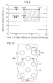
- Fig. 10 is an enlarged plan view showing the surface structure of a door handle adopted in Example
- Fig. 11 is an enlarged cross sectional view taken along the line C-C in Fig. 10 .
- the concave portion 11 shown in Fig. 10 is formed on the internal wall face 9 of the vehicular door grip 7 as shown in Fig. 1 .
- each of the concave portions 11 is formed substantially in an elliptical shape which is close to a true circle in plan view, where a long diameter as a length of a long axis is 1.8 mm while a short diameter as a length of a short axis is 1.6 mm.
- these concave portions 11 are disposed at apexes of a square having a side of 6 mm, and one concave portion 11 is disposed in the center portion of the square. Many of the thus disposed concave portions 11 are disposed regularly and repeatedly.
- fine convex portions 21 are formed on both the surface of the concave portion 11 and the surface of the plane portion 13.
- the diameter d of the convex portion 21 is in a range of 20 ⁇ m to 30 ⁇ m and the height h of the convex portion 21 is 20 ⁇ m.
- the edge R of the concave portion 11 is 1 mm.
- the touch feeling of the door grip 7 was verified by gripping the door grip 7. It has been found that a more delicate and softer touch feeling was obtained compared with a conventional door grip.
- the present invention is not limited to the above embodiment, and can be variously varied and modified based on the technical concept of the present invention.
- hemispherical concave portions 11 are each disposed in a position corresponding to an apex of a regular hexagon 29 denoted by an alternate long and short dashed line.
- substantially the same touch feeling can be obtained from any directions, i.e., upper, lower, right, left and the like, on the face in Fig. 12 .
- a plurality of fine convex portions each having a diameter of 15 ⁇ m to 40 ⁇ m are formed on the surface. Therefore, when the hand's finger of the human being touches the surface, the human being can obtain a delicate-and-soft touch feeling which is felt by the fingerprint of the hand's finger.
Abstract
Description
- The present invention relates to a surface structure of an article.
- Ordinarily, interior components are disposed in a vehicular room of an automobile, an electric train and the like, thereby improving external view or touch feeling (for example, refer to
Patent Literature 1 and the like). - A vehicular interior component described in this
Patent Literature 1 is applied to a lengthy member such as vehicular weather strip and the like, and is formed with a lengthy molded article main body and an ornament layer disposed on the surface of the lengthy molded article main body. A plurality of linear groove portions extending linearly are formed on the surface of this ornament layer. The linear groove portions are disposed at specified intervals in a direction perpendicular to a longitudinal direction of the lengthy member. Many fine concave-convex patterns smaller than a concave-convex shape defined by the linear groove portion are formed on a surface of the linear groove portion. - [Patent Literature 1] Japanese Patent Application Laid-Open No.
2005-263197 - However, with respect to the vehicular interior component shown in the above background art, the size of the linear groove portion and the size of the concave-convex pattern formed on the surface of the linear groove portion are not specifically defined. Therefore, when a hand's finger of a human being touches the surface of the interior component, it is difficult for the human being to obtain a delicate-and-soft touch feeling which is felt by the fingerprint of the hand's finger.
- Therefore, the present invention has been made in view of the above circumstances. It is an object of the present invention to provide a surface structure of an article which allows a human being to obtain a delicate-and-soft touch feeling which is felt by the fingerprint of the hand's finger of the human being.
- For achieving the above object, the surface structure of an article according to the present invention has such a main feature that a plurality of fine convex portions each having a diameter in a range of 15 µm to 40 µm are formed on the surface of the structure.
- In the surface structure of an article according to the present invention, a plurality of fine convex portions each having a diameter in a range of 15 µm to 40 µm are formed on the surface of the structure. Therefore, when a finger of the human being touches the surface, a delicate-and-soft touch feeling which is felt by the fingerprint of the hand's finger can be obtained.
-
- [
Fig. 1] Fig. 1 is a perspective view of a door equipped with a door trim according to an embodiment of the present invention, where the door is viewed from a vehicular inside. - [
Fig. 2] Fig. 2 is a perspective view where the surface of the door grip inFig. 1 is enlarged. - [
Fig. 3] Fig. 3 is a plan view ofFig. 2 . - [
Fig. 4] Fig. 4 is a cross sectional view taken along the line A-A inFig. 3 . - [
Fig. 5] Fig. 5 is a cross sectional view whereFig. 4 is enlarged. - [
Fig. 6] Fig. 6 is a schematic view where a fingerprint of a hand's finger of the human being is enlarged. - [
Fig. 7] Fig. 7 is an enlarged schematic view showing a state in which a fingerprint of a hand's finger abuts on an edge portion of a concave portion formed on the surface of a door grip. - [
Fig. 8] Fig. 8 is an enlarged schematic view showing a state in which a fingerprint of a hand's finger abuts on an edge portion of a concave portion in a door grip according to a comparative example. - [
Fig. 9] Fig. 9 is a graph showing a relationship between an edge R of an edge portion of a concave portion and a height of a convex portion formed in an edge portion of a concave portion. - [
Fig. 10] Fig. 10 is an enlarged plan view showing a surface structure of a door handle adopted for Example. - [
Fig. 11] Fig. 11 is an enlarged cross sectional view taken along the line C-C inFig. 10 . - [
Fig. 12] Fig. 12 is a plan view showing locations of the concave portions according to another embodiment. - Hereinafter, an embodiment of the present invention is to be set forth based on drawings.
-
Fig. 1 is a perspective view of a door equipped with the door trim according to the embodiment of the present invention, where the door is viewed from a vehicular inside. - A
door 1 has a door main body where an outer panel and an inner panel are joined with each other, and adoor trim 3 which is fitted to the vehicular inside of the door main body. Anarmrest 5 protruding to the vehicular inside is disposed at a center portion in a height direction of thedoor trim 3, and adoor grip 7 for a passenger to grip for opening and closing thedoor 1 is disposed on anupper face 5a of thearmrest 5. In the upper face of thearmrest 5, thedoor grip 7 is disposed in a form of concave. On aninternal wall face 9 in the vehicular inside among internal wall faces defining thedoor grip 7, a below-described surface structure according to the embodiment of the present invention is disposed. -
Fig. 2 is a perspective view where the surface of thedoor grip 7 inFig. 1 is enlarged,Fig. 3 is a plan view ofFig. 2 , andFig. 4 is a cross sectional view taken along the line A-A inFig. 3 . - On the surface of the
internal wall face 9 of thedoor grip 7, a plurality ofconcave portions 11 are disposed at specified intervals relative to each other. Theseconcave portions 11 are each formed substantially in a hemispherical shape concaved toward a backface side. Between theconcave portions flat plane portion 13 is formed. Moreover, a diameter D of theconcave portion 11 is preferably in a range of 0.5 mm to 2.0 mm while a depth H of theconcave portion 11 is preferably in a range of 60 µm to 350 µm. Here, the diameter D of theconcave portion 11 denotes a distance between outermost stop ends of respective edges R of theedge portions 15 while the depth H of theconcave portion 11 denotes a distance from a bottom face of theconcave portion 11 to theplane portion 13 of the internal wall face. Moreover, the edge R (curvature radius) of the cross section of theedge portion 15 in the vicinity of the surface of theconcave portion 11 is preferably in a range of 1 mm to 2 mm. -
Fig. 5 is a cross sectional view whereFig. 4 is enlarged. - Though omitted from
Fig. 4 , a plurality of fineconvex portions 21 each formed having a diameter d smaller than the diameter D of theconcave portion 11 are continuously formed on the whole surface of not only theedge portion 15 of theconcave portion 11, but also the entireconcave portion 11 and theplane portion 13. Theseconvex portions 21 are each formed in a hemisphere shape protruding to the surface side. The diameter d is preferably in a range of 15 µm to 40 µm while the height h is preferably in a range of 15 µm to 30 µm. In addition, theconvex portion 21 may be formed at least in theedge portion 15 of theconcave portion 11. However, as shown according to the present embodiment, theconvex portion 21 is preferably formed also in the entireconcave portion 11 and in theplane portion 13 other than theconcave portion 11. -
Fig. 6 shows afingerprint 23 of a hand's finger of the human being, whereFig. 6(a) is a schematic view of thefingerprint 23 which is enlarged whileFig. 6(b) is a cross sectional view ofFig. 6(a) taken along the line B-B inFig. 6(a) . - On the surface of the hand's finger, as is well known, the
fingerprint 23 forming various patterns is formed. The pattern inFig. 6 denotes aspiral fingerprint 23 formed withlinear objects 25 in a circular or spiral shape. Theselinear objects 25 are each formed in a convex shape protruding outward and are disposed intermittently along a longitudinal direction. In addition, the area between thelinear objects 25 is formed in aflat portion 27. -
Fig. 7 is an enlarged schematic view showing a state in which thefingerprint 23 of the hand's finger abuts on theedge portion 15 of theconcave portion 11 formed on the surface of thedoor grip 7. - On the surface of the
edge portion 15 of theconcave portion 11 drawn at the lower-right part inFig. 7 , like on (or in) other portions, the substantially hemispherical fine convexportions 21 protruding toward the surface side are formed. Theconvex portions 21 are continuously formed in such a configuration as not having a gap between the adjacentconvex portions 21. Moreover, a large hemisphere drawn in the upper-left part inFig. 7 is thelinear object 25 constituting thefingerprint 23 of the hand's finger. According to the present embodiment, fourconvex portions 21 abut on onelinear object 25. As set forth above, when the number ofconvex portions 21 abutting on thelinear object 25 constituting thefingerprint 23 of the hand's finger is four, a tactile organ (not shown in drawings) disposed inside the finger is stimulated, thereby allowing the human being to feel "delicate-and-soft." Here, "delicate" expresses a very sensitive meaning that the human being can recognize by a light touch. Moreover, inFig. 7 , the edge R of theedge portion 15 is 1 mm, the height h of theconvex portion 21 is 20 µm, and the diameter d of theconvex portion 21 is 40 µm. -
Fig. 8 is an enlarged schematic view showing a state in which thefingerprint 23 of the hand's finger abuts on theedge portion 15 of theconcave portion 11 in thedoor grip 7 according to a comparative example. - Contrary to the above-described
Fig. 7 , as shown inFig. 8 , when the edge R of theedge portion 1 is small, three (less than four)convex portions 21 abut on onelinear object 25 constituting thefingerprint 23 of the hand's finger. Thus, when the edge R is small, the curvature factor of theedge portion 15 is large (edge R is small). Therefore, even when theconvex portions 21 have the same size or thelinear objects 25 of thefingerprint 23 have the same dimension, the number ofconvex portions 21 abutting on onelinear object 25 is decreased, thus preventing the human being from feeling a delicate-and-soft touch feeling which is felt by thefingerprint 23 of the hand's finger. Moreover, inFig. 8 , the edge R of theedge portion 15 is 0.5 mm, the height h of theconvex portion 21 is 20 µm, and the diameter d of theconvex portion 21 is 40 µm. -
Fig. 9 is a graph showing the relationship between the edge R of theedge portion 15 of theconcave portion 11 and the height h of theconvex portion 21 formed in theedge portion 15 of theconcave portion 11. - The abscissa axis of
Fig. 9 denotes the edge R (curvature radius) in theedge portion 15 of theconcave portion 11 while the ordinate axis ofFig. 9 denotes the height h of theconvex portion 21. Moreover, the numbers described above black circles each denote the number ofconvex portions 21 on which thelinear object 25 of thefingerprint 23 abuts. - According to this graph, it is apparent that by setting conditions in a range of a hatched rectangular portion, the
linear object 25 of thefingerprint 23 abuts on the fourconvex portions 21. Specifically, the edge R of theedge portion 15 of theconcave portion 11 is in a range of 1 mm to 2 mm, and the height h of theconvex portion 21 is in a range of 15 µm to 30 µm. Thus, when thelinear object 25 of thefingerprint 23 abuts on the fourconvex portions 21, the tactile organ on the backside of thefingerprint 23 is stimulated, thus allowing the human being to obtain a delicate-and-soft touch feeling. - Hereinafter, operations and effects of the present embodiment are to be set forth.
- (1) In the vehicular interior component according to the present embodiment, a plurality of
concave portions 11 are so disposed on the surface as to have intervals relative to each other and a plurality of fineconvex portions 21 each having a specified diameter smaller than the diameter of theconcave portion 11 are disposed on the surface of at least theedge portion 15 of theconcave portion 11. Therefore, when the hand touches the surface of the vehicular interior component, the proper number ofconvex portions 21 abut on thelinear object 25 constituting thefingerprint 23 of the hand's finger, to thereby provide a delicate-and-soft touch feeling. - (2) The
concave portion 11 is formed to have the diameter D in a range of 0.5 mm to 2.0 mm and the depth H in a range of 60 µm to 350 µm. In this way, forming theconcave portion 11 having a diameter D and a depth H in the specified ranges allows the proper number (four) ofconvex portions 21 to abut on thelinear object 25 constituting thefingerprint 23 of the hand's finger, to thereby provide a delicate-and-soft touch feeling. - (3) The curvature radius R of the cross section in the
edge portion 15 of theconcave portion 11 is set in a range of 1 mm to 2 mm. In this way, forming the curvature radius D of the cross section in theedge portion 15 of theconcave portion 11 in the certain range allows the proper number (four) ofconvex portions 21 to abut on thelinear object 25 constituting thefingerprint 23 of the hand's finger, to thereby provide a delicate-and-soft touch feeling. - (4) The
convex portion 21 is formed to have the diameter d in a range of 15 µm to 40 µm and the height h in a range of 15 µm to 30 µm. In this way, forming theconcave portion 11 having a diameter d and a height h in the specified ranges allows the proper number (four) ofconvex portions 21 to abut on thelinear object 25 constituting thefingerprint 23 of the hand's finger, to thereby provide a delicate-and-soft touch feeling. - (5) The concave portion is formed in a substantially hemispherical shape. Therefore, dependency on orientation of the
linear object 25 of thefingerprint 23 is low, allowing the human being to have a constant touch feeling even when the human being touches the concave portion from any directions. - Hereinafter, the present invention is to be specifically set forth referring to Example.
-
Fig. 10 is an enlarged plan view showing the surface structure of a door handle adopted in Example, andFig. 11 is an enlarged cross sectional view taken along the line C-C inFig. 10 . - The
concave portion 11 shown inFig. 10 is formed on theinternal wall face 9 of thevehicular door grip 7 as shown inFig. 1 . Specifically, each of theconcave portions 11 is formed substantially in an elliptical shape which is close to a true circle in plan view, where a long diameter as a length of a long axis is 1.8 mm while a short diameter as a length of a short axis is 1.6 mm. Moreover, in plan view, theseconcave portions 11 are disposed at apexes of a square having a side of 6 mm, and oneconcave portion 11 is disposed in the center portion of the square. Many of the thus disposedconcave portions 11 are disposed regularly and repeatedly. - Moreover, as shown in
Fig. 11 , fineconvex portions 21 are formed on both the surface of theconcave portion 11 and the surface of theplane portion 13. The diameter d of theconvex portion 21 is in a range of 20 µm to 30 µm and the height h of theconvex portion 21 is 20 µm. Moreover, the edge R of theconcave portion 11 is 1 mm. - The touch feeling of the
door grip 7 was verified by gripping thedoor grip 7. It has been found that a more delicate and softer touch feeling was obtained compared with a conventional door grip. - Moreover, the present invention is not limited to the above embodiment, and can be variously varied and modified based on the technical concept of the present invention.
- For example, as shown in
Fig. 12 , in the case of disposing theconcave portions 11 each formed in a hemispherical shape, it is preferable that such hemisphericalconcave portions 11 are each disposed in a position corresponding to an apex of aregular hexagon 29 denoted by an alternate long and short dashed line. By this, substantially the same touch feeling can be obtained from any directions, i.e., upper, lower, right, left and the like, on the face inFig. 12 . - The entire contents of the Japanese Patent Application No.
2008-293138 - By the surface structure of the article according to the present invention, a plurality of fine convex portions each having a diameter of 15 µm to 40 µm are formed on the surface. Therefore, when the hand's finger of the human being touches the surface, the human being can obtain a delicate-and-soft touch feeling which is felt by the fingerprint of the hand's finger.
Claims (6)
- A surface structure of an article, comprising:a surface which is formed with a plurality of fine convex portions each having a diameter in a range of 15 µm to 40 µm.
- A surface structure of an article, comprising:a surface which is formed with a plurality of concave portions so disposed on the surface as to have intervals relative to each other,wherein a curvature radius of a cross section in an edge portion of the concave portion is set in a range of 1 mm to 2 mm, and a plurality of the convex portions are formed on a surface of at least the edge portion of the concave portion.
- The surface structure of the article according to claim 1 or 2, wherein the concave portion is formed to have a diameter in a range of 0.5 mm to 2.0 mm and a depth in a range of 60 µm to 350 µm.
- The surface structure of the article according to any one of claims 1 to 3, wherein the convex portion is formed to have a height in a range of 15 µm to 30 µm.
- The surface structure of the article according to any one of claims 1 to 4, wherein the concave portion is formed in a substantially hemispherical shape.
- The surface structure of the article according to any one of claims 1 to 5, wherein the article is a vehicular interior component.
Applications Claiming Priority (2)
| Application Number | Priority Date | Filing Date | Title |
|---|---|---|---|
| JP2008293138A JP5253103B2 (en) | 2008-11-17 | 2008-11-17 | Interior parts for vehicles |
| PCT/JP2009/069498 WO2010055948A1 (en) | 2008-11-17 | 2009-11-17 | Surface structure for article |
Publications (3)
| Publication Number | Publication Date |
|---|---|
| EP2357110A1 true EP2357110A1 (en) | 2011-08-17 |
| EP2357110A4 EP2357110A4 (en) | 2012-10-24 |
| EP2357110B1 EP2357110B1 (en) | 2014-01-08 |
Family
ID=42170077
Family Applications (1)
| Application Number | Title | Priority Date | Filing Date |
|---|---|---|---|
| EP09826193.6A Active EP2357110B1 (en) | 2008-11-17 | 2009-11-17 | Surface structure for article |
Country Status (6)
| Country | Link |
|---|---|
| US (1) | US10807541B2 (en) |
| EP (1) | EP2357110B1 (en) |
| JP (1) | JP5253103B2 (en) |
| KR (1) | KR101324368B1 (en) |
| CN (1) | CN102216120B (en) |
| WO (1) | WO2010055948A1 (en) |
Cited By (1)
| Publication number | Priority date | Publication date | Assignee | Title |
|---|---|---|---|---|
| EP2724833A4 (en) * | 2011-06-24 | 2015-03-11 | Nissan Motor | Surface structure of article |
Families Citing this family (8)
| Publication number | Priority date | Publication date | Assignee | Title |
|---|---|---|---|---|
| JP5418959B2 (en) * | 2008-12-25 | 2014-02-19 | 日産自動車株式会社 | Resin molding |
| JP2012162233A (en) * | 2011-02-09 | 2012-08-30 | Hino Motors Ltd | Guard bar |
| WO2012147829A1 (en) | 2011-04-27 | 2012-11-01 | 株式会社タイカ | Water pressure transfer method, coating agent for water pressure transfer film, and water pressure transfer article |
| WO2012169233A1 (en) * | 2011-06-07 | 2012-12-13 | 日産自動車株式会社 | Surface structure for article |
| JP6010784B2 (en) * | 2012-08-28 | 2016-10-19 | トヨタ車体株式会社 | Automobile interior parts, molds for car interior parts, and manufacturing method for car interior parts |
| KR102100669B1 (en) * | 2016-09-27 | 2020-05-27 | (주)엘지하우시스 | Manufacturing method of automotive interior material and automotive interior material |
| KR101905993B1 (en) * | 2016-10-31 | 2018-10-10 | 현대자동차주식회사 | Interior parts for vehicle and method for manufacturing the same |
| CN106740685A (en) * | 2016-12-26 | 2017-05-31 | 深圳市中舜创新科技有限公司 | Vehicle lockset with push type fingerprint sensor |
Citations (3)
| Publication number | Priority date | Publication date | Assignee | Title |
|---|---|---|---|---|
| JP2002146087A (en) * | 2000-11-15 | 2002-05-22 | Tokai Kogyo Co Ltd | Decorative material and method for producing the same |
| WO2007144469A1 (en) * | 2006-06-14 | 2007-12-21 | Avantone Oy | Anti-counterfeit hologram |
| EP2014435A1 (en) * | 2007-06-06 | 2009-01-14 | Nissan Motor Co., Ltd. | Skin material, skin material production method and composite skin for automotive interior trim |
Family Cites Families (23)
| Publication number | Priority date | Publication date | Assignee | Title |
|---|---|---|---|---|
| JPH07106625B2 (en) * | 1989-03-10 | 1995-11-15 | 大日本印刷株式会社 | Makeup sheet |
| JPH0535864Y2 (en) * | 1989-06-27 | 1993-09-10 | ||
| JPH081895A (en) * | 1994-06-21 | 1996-01-09 | Dainippon Printing Co Ltd | Decorative sheet and production thereof |
| JPH09239739A (en) | 1996-03-12 | 1997-09-16 | Sony Corp | Surface structure of molded object, molding thereof and mold surface finish processing method |
| US6136415A (en) * | 1997-05-27 | 2000-10-24 | R + S Technik Gmbh | Vehicle interior trim panel with a soft-touch foam layer, and a method and apparatus for making the same |
| TW440519B (en) * | 1999-04-23 | 2001-06-16 | Dainippon Printing Co Ltd | Shaped sheet and method for producing the same |
| JP4635353B2 (en) * | 2001-03-06 | 2011-02-23 | 日本エクスラン工業株式会社 | Painted metal plate with excellent moisture absorption and desorption properties |
| US6749794B2 (en) * | 2001-08-13 | 2004-06-15 | R + S Technik Gmbh | Method and apparatus for molding components with molded-in surface texture |
| WO2003101734A1 (en) * | 2002-05-30 | 2003-12-11 | Dai Nippon Printing Co., Ltd. | Decorative material and decorative sheet |
| JP4175960B2 (en) | 2002-09-26 | 2008-11-05 | 株式会社神戸製鋼所 | Metal plate and molded product using the same |
| US7431975B2 (en) * | 2002-11-29 | 2008-10-07 | Dzs, L.L.C. | Textured composite material |
| US8216659B2 (en) * | 2003-07-01 | 2012-07-10 | Dzs, Llc | Spring-like textured composite floorcovering |
| EP1663685B1 (en) * | 2003-09-17 | 2011-08-03 | Tokai Kogyo Co., Ltd. | Long ornament member and method for manufacturing the same |
| BRPI0416595B1 (en) | 2003-11-15 | 2014-06-17 | Basf Ag | SUBSTRATE, AND PROCEDURE TO PRODUCE A FINISH PROVIDED WITH A SUBSTRATE |
| JP4379715B2 (en) * | 2004-02-19 | 2009-12-09 | 豊田合成株式会社 | Long molded product |
| AT8006U1 (en) * | 2004-06-07 | 2005-12-15 | Schaefer Philipp | SUPPORTED ON ITS TOP WITH A SINGLE CARRIER |
| JP2006068972A (en) * | 2004-08-31 | 2006-03-16 | World Etching:Kk | Mold for molding resin, gloss-reducing method therefor and resin molded product |
| JP2007022000A (en) * | 2005-07-20 | 2007-02-01 | Honda Motor Co Ltd | Surface structure of object |
| US7636538B2 (en) | 2006-04-27 | 2009-12-22 | Seiko Epson Corporation | Layer-thickness restriction member, developing device, method for manufacturing restriction blade, and blade-forming mold |
| JP4844218B2 (en) * | 2006-04-27 | 2011-12-28 | セイコーエプソン株式会社 | Layer thickness regulating member, developing device, image forming apparatus, and image forming system |
| US20070261224A1 (en) * | 2006-05-11 | 2007-11-15 | Dow Global Technologies Inc. | Methods and articles in having a fringed microprotrusion surface structure |
| JP4877068B2 (en) | 2007-05-22 | 2012-02-15 | 富士電機株式会社 | Software development support program, software development support method |
| JP5643090B2 (en) * | 2008-07-31 | 2014-12-17 | セーレン株式会社 | Decorative surface structure of synthetic resin molded product, manufacturing method thereof, and automobile interior part |
-
2008
- 2008-11-17 JP JP2008293138A patent/JP5253103B2/en active Active
-
2009
- 2009-11-17 US US13/129,217 patent/US10807541B2/en active Active
- 2009-11-17 WO PCT/JP2009/069498 patent/WO2010055948A1/en active Application Filing
- 2009-11-17 CN CN200980145958.7A patent/CN102216120B/en active Active
- 2009-11-17 KR KR1020117013769A patent/KR101324368B1/en active IP Right Grant
- 2009-11-17 EP EP09826193.6A patent/EP2357110B1/en active Active
Patent Citations (3)
| Publication number | Priority date | Publication date | Assignee | Title |
|---|---|---|---|---|
| JP2002146087A (en) * | 2000-11-15 | 2002-05-22 | Tokai Kogyo Co Ltd | Decorative material and method for producing the same |
| WO2007144469A1 (en) * | 2006-06-14 | 2007-12-21 | Avantone Oy | Anti-counterfeit hologram |
| EP2014435A1 (en) * | 2007-06-06 | 2009-01-14 | Nissan Motor Co., Ltd. | Skin material, skin material production method and composite skin for automotive interior trim |
Non-Patent Citations (1)
| Title |
|---|
| See also references of WO2010055948A1 * |
Cited By (1)
| Publication number | Priority date | Publication date | Assignee | Title |
|---|---|---|---|---|
| EP2724833A4 (en) * | 2011-06-24 | 2015-03-11 | Nissan Motor | Surface structure of article |
Also Published As
| Publication number | Publication date |
|---|---|
| EP2357110B1 (en) | 2014-01-08 |
| US10807541B2 (en) | 2020-10-20 |
| KR101324368B1 (en) | 2013-11-01 |
| JP5253103B2 (en) | 2013-07-31 |
| WO2010055948A1 (en) | 2010-05-20 |
| CN102216120B (en) | 2015-09-09 |
| US20110287220A1 (en) | 2011-11-24 |
| JP2010120399A (en) | 2010-06-03 |
| CN102216120A (en) | 2011-10-12 |
| KR20110091872A (en) | 2011-08-16 |
| EP2357110A4 (en) | 2012-10-24 |
Similar Documents
| Publication | Publication Date | Title |
|---|---|---|
| US10807541B2 (en) | Surface structure of article | |
| EP2998109B1 (en) | Multilayer composite interior component | |
| EP3045305B1 (en) | Multilayer composite interior component | |
| US9573341B2 (en) | Multi-layer composite part | |
| TWI545036B (en) | Laminated composite interior component | |
| EP3330133B1 (en) | Stacked composite interior component | |
| EP3210770B1 (en) | Stacked composite interior part | |
| EP3235688B1 (en) | Multilayer composite interior component | |
| JP5950814B2 (en) | Overlapped composite parts | |
| EP3150441B1 (en) | Overlaid composite interior component | |
| US11794442B2 (en) | Superposition interior component | |
| EP3992008A1 (en) | Vehicle interior member and vehicle interior member manufacturing method | |
| US11981269B2 (en) | Vehicle interior member and vehicle interior member manufacturing method | |
| JP2011079455A (en) | Deck board for automobile | |
| JP2019001329A (en) | Seal member holding structure |
Legal Events
| Date | Code | Title | Description |
|---|---|---|---|
| PUAI | Public reference made under article 153(3) epc to a published international application that has entered the european phase |
Free format text: ORIGINAL CODE: 0009012 |
|
| 17P | Request for examination filed |
Effective date: 20110609 |
|
| AK | Designated contracting states |
Kind code of ref document: A1 Designated state(s): AT BE BG CH CY CZ DE DK EE ES FI FR GB GR HR HU IE IS IT LI LT LU LV MC MK MT NL NO PL PT RO SE SI SK SM TR |
|
| DAX | Request for extension of the european patent (deleted) | ||
| A4 | Supplementary search report drawn up and despatched |
Effective date: 20120925 |
|
| RIC1 | Information provided on ipc code assigned before grant |
Ipc: B60J 5/04 20060101ALI20120919BHEP Ipc: B60J 5/00 20060101ALI20120919BHEP Ipc: B44C 5/00 20060101ALI20120919BHEP Ipc: B44C 1/24 20060101ALI20120919BHEP Ipc: B60R 13/02 20060101AFI20120919BHEP |
|
| GRAP | Despatch of communication of intention to grant a patent |
Free format text: ORIGINAL CODE: EPIDOSNIGR1 |
|
| RIC1 | Information provided on ipc code assigned before grant |
Ipc: B60R 13/02 20060101AFI20130513BHEP Ipc: B44C 5/00 20060101ALI20130513BHEP Ipc: B60J 5/00 20060101ALI20130513BHEP Ipc: B60J 5/04 20060101ALI20130513BHEP Ipc: B44C 1/24 20060101ALI20130513BHEP |
|
| INTG | Intention to grant announced |
Effective date: 20130620 |
|
| RIN1 | Information on inventor provided before grant (corrected) |
Inventor name: MOCHIYAMA HIROMI Inventor name: TAKESUE NAOYUKI Inventor name: TAKEUCHI, TAKASHI Inventor name: KANG, YEON-YI Inventor name: TANAKA YOSHIHIRO Inventor name: BAN, AKANE Inventor name: TAMURAYA, MAKOTO Inventor name: FUJIMOTO HIDEO Inventor name: SANO AKIHITO |
|
| GRAS | Grant fee paid |
Free format text: ORIGINAL CODE: EPIDOSNIGR3 |
|
| GRAA | (expected) grant |
Free format text: ORIGINAL CODE: 0009210 |
|
| AK | Designated contracting states |
Kind code of ref document: B1 Designated state(s): AT BE BG CH CY CZ DE DK EE ES FI FR GB GR HR HU IE IS IT LI LT LU LV MC MK MT NL NO PL PT RO SE SI SK SM TR |
|
| REG | Reference to a national code |
Ref country code: GB Ref legal event code: FG4D |
|
| REG | Reference to a national code |
Ref country code: CH Ref legal event code: EP |
|
| REG | Reference to a national code |
Ref country code: IE Ref legal event code: FG4D |
|
| REG | Reference to a national code |
Ref country code: AT Ref legal event code: REF Ref document number: 648504 Country of ref document: AT Kind code of ref document: T Effective date: 20140215 |
|
| REG | Reference to a national code |
Ref country code: DE Ref legal event code: R096 Ref document number: 602009021388 Country of ref document: DE Effective date: 20140220 |
|
| REG | Reference to a national code |
Ref country code: AT Ref legal event code: MK05 Ref document number: 648504 Country of ref document: AT Kind code of ref document: T Effective date: 20140108 |
|
| REG | Reference to a national code |
Ref country code: NL Ref legal event code: VDEP Effective date: 20140108 |
|
| REG | Reference to a national code |
Ref country code: LT Ref legal event code: MG4D |
|
| PG25 | Lapsed in a contracting state [announced via postgrant information from national office to epo] |
Ref country code: IS Free format text: LAPSE BECAUSE OF FAILURE TO SUBMIT A TRANSLATION OF THE DESCRIPTION OR TO PAY THE FEE WITHIN THE PRESCRIBED TIME-LIMIT Effective date: 20140508 Ref country code: NO Free format text: LAPSE BECAUSE OF FAILURE TO SUBMIT A TRANSLATION OF THE DESCRIPTION OR TO PAY THE FEE WITHIN THE PRESCRIBED TIME-LIMIT Effective date: 20140408 Ref country code: LT Free format text: LAPSE BECAUSE OF FAILURE TO SUBMIT A TRANSLATION OF THE DESCRIPTION OR TO PAY THE FEE WITHIN THE PRESCRIBED TIME-LIMIT Effective date: 20140108 |
|
| PG25 | Lapsed in a contracting state [announced via postgrant information from national office to epo] |
Ref country code: PT Free format text: LAPSE BECAUSE OF FAILURE TO SUBMIT A TRANSLATION OF THE DESCRIPTION OR TO PAY THE FEE WITHIN THE PRESCRIBED TIME-LIMIT Effective date: 20140508 Ref country code: ES Free format text: LAPSE BECAUSE OF FAILURE TO SUBMIT A TRANSLATION OF THE DESCRIPTION OR TO PAY THE FEE WITHIN THE PRESCRIBED TIME-LIMIT Effective date: 20140108 Ref country code: AT Free format text: LAPSE BECAUSE OF FAILURE TO SUBMIT A TRANSLATION OF THE DESCRIPTION OR TO PAY THE FEE WITHIN THE PRESCRIBED TIME-LIMIT Effective date: 20140108 Ref country code: FI Free format text: LAPSE BECAUSE OF FAILURE TO SUBMIT A TRANSLATION OF THE DESCRIPTION OR TO PAY THE FEE WITHIN THE PRESCRIBED TIME-LIMIT Effective date: 20140108 Ref country code: NL Free format text: LAPSE BECAUSE OF FAILURE TO SUBMIT A TRANSLATION OF THE DESCRIPTION OR TO PAY THE FEE WITHIN THE PRESCRIBED TIME-LIMIT Effective date: 20140108 Ref country code: SE Free format text: LAPSE BECAUSE OF FAILURE TO SUBMIT A TRANSLATION OF THE DESCRIPTION OR TO PAY THE FEE WITHIN THE PRESCRIBED TIME-LIMIT Effective date: 20140108 Ref country code: CY Free format text: LAPSE BECAUSE OF FAILURE TO SUBMIT A TRANSLATION OF THE DESCRIPTION OR TO PAY THE FEE WITHIN THE PRESCRIBED TIME-LIMIT Effective date: 20140108 |
|
| PG25 | Lapsed in a contracting state [announced via postgrant information from national office to epo] |
Ref country code: BE Free format text: LAPSE BECAUSE OF FAILURE TO SUBMIT A TRANSLATION OF THE DESCRIPTION OR TO PAY THE FEE WITHIN THE PRESCRIBED TIME-LIMIT Effective date: 20140108 Ref country code: LV Free format text: LAPSE BECAUSE OF FAILURE TO SUBMIT A TRANSLATION OF THE DESCRIPTION OR TO PAY THE FEE WITHIN THE PRESCRIBED TIME-LIMIT Effective date: 20140108 Ref country code: HR Free format text: LAPSE BECAUSE OF FAILURE TO SUBMIT A TRANSLATION OF THE DESCRIPTION OR TO PAY THE FEE WITHIN THE PRESCRIBED TIME-LIMIT Effective date: 20140108 |
|
| REG | Reference to a national code |
Ref country code: DE Ref legal event code: R097 Ref document number: 602009021388 Country of ref document: DE |
|
| PG25 | Lapsed in a contracting state [announced via postgrant information from national office to epo] |
Ref country code: EE Free format text: LAPSE BECAUSE OF FAILURE TO SUBMIT A TRANSLATION OF THE DESCRIPTION OR TO PAY THE FEE WITHIN THE PRESCRIBED TIME-LIMIT Effective date: 20140108 Ref country code: CZ Free format text: LAPSE BECAUSE OF FAILURE TO SUBMIT A TRANSLATION OF THE DESCRIPTION OR TO PAY THE FEE WITHIN THE PRESCRIBED TIME-LIMIT Effective date: 20140108 Ref country code: DK Free format text: LAPSE BECAUSE OF FAILURE TO SUBMIT A TRANSLATION OF THE DESCRIPTION OR TO PAY THE FEE WITHIN THE PRESCRIBED TIME-LIMIT Effective date: 20140108 Ref country code: RO Free format text: LAPSE BECAUSE OF FAILURE TO SUBMIT A TRANSLATION OF THE DESCRIPTION OR TO PAY THE FEE WITHIN THE PRESCRIBED TIME-LIMIT Effective date: 20140108 |
|
| PLBE | No opposition filed within time limit |
Free format text: ORIGINAL CODE: 0009261 |
|
| STAA | Information on the status of an ep patent application or granted ep patent |
Free format text: STATUS: NO OPPOSITION FILED WITHIN TIME LIMIT |
|
| PG25 | Lapsed in a contracting state [announced via postgrant information from national office to epo] |
Ref country code: SK Free format text: LAPSE BECAUSE OF FAILURE TO SUBMIT A TRANSLATION OF THE DESCRIPTION OR TO PAY THE FEE WITHIN THE PRESCRIBED TIME-LIMIT Effective date: 20140108 Ref country code: PL Free format text: LAPSE BECAUSE OF FAILURE TO SUBMIT A TRANSLATION OF THE DESCRIPTION OR TO PAY THE FEE WITHIN THE PRESCRIBED TIME-LIMIT Effective date: 20140108 |
|
| 26N | No opposition filed |
Effective date: 20141009 |
|
| REG | Reference to a national code |
Ref country code: DE Ref legal event code: R097 Ref document number: 602009021388 Country of ref document: DE Effective date: 20141009 |
|
| PG25 | Lapsed in a contracting state [announced via postgrant information from national office to epo] |
Ref country code: SI Free format text: LAPSE BECAUSE OF FAILURE TO SUBMIT A TRANSLATION OF THE DESCRIPTION OR TO PAY THE FEE WITHIN THE PRESCRIBED TIME-LIMIT Effective date: 20140108 |
|
| PG25 | Lapsed in a contracting state [announced via postgrant information from national office to epo] |
Ref country code: LU Free format text: LAPSE BECAUSE OF FAILURE TO SUBMIT A TRANSLATION OF THE DESCRIPTION OR TO PAY THE FEE WITHIN THE PRESCRIBED TIME-LIMIT Effective date: 20141117 Ref country code: MC Free format text: LAPSE BECAUSE OF FAILURE TO SUBMIT A TRANSLATION OF THE DESCRIPTION OR TO PAY THE FEE WITHIN THE PRESCRIBED TIME-LIMIT Effective date: 20140108 |
|
| REG | Reference to a national code |
Ref country code: CH Ref legal event code: PL |
|
| PG25 | Lapsed in a contracting state [announced via postgrant information from national office to epo] |
Ref country code: LI Free format text: LAPSE BECAUSE OF NON-PAYMENT OF DUE FEES Effective date: 20141130 Ref country code: CH Free format text: LAPSE BECAUSE OF NON-PAYMENT OF DUE FEES Effective date: 20141130 |
|
| REG | Reference to a national code |
Ref country code: IE Ref legal event code: MM4A |
|
| REG | Reference to a national code |
Ref country code: FR Ref legal event code: PLFP Year of fee payment: 7 |
|
| PG25 | Lapsed in a contracting state [announced via postgrant information from national office to epo] |
Ref country code: IE Free format text: LAPSE BECAUSE OF NON-PAYMENT OF DUE FEES Effective date: 20141117 |
|
| PG25 | Lapsed in a contracting state [announced via postgrant information from national office to epo] |
Ref country code: SM Free format text: LAPSE BECAUSE OF FAILURE TO SUBMIT A TRANSLATION OF THE DESCRIPTION OR TO PAY THE FEE WITHIN THE PRESCRIBED TIME-LIMIT Effective date: 20140108 |
|
| PG25 | Lapsed in a contracting state [announced via postgrant information from national office to epo] |
Ref country code: IT Free format text: LAPSE BECAUSE OF FAILURE TO SUBMIT A TRANSLATION OF THE DESCRIPTION OR TO PAY THE FEE WITHIN THE PRESCRIBED TIME-LIMIT Effective date: 20140108 Ref country code: GR Free format text: LAPSE BECAUSE OF FAILURE TO SUBMIT A TRANSLATION OF THE DESCRIPTION OR TO PAY THE FEE WITHIN THE PRESCRIBED TIME-LIMIT Effective date: 20140409 Ref country code: BG Free format text: LAPSE BECAUSE OF FAILURE TO SUBMIT A TRANSLATION OF THE DESCRIPTION OR TO PAY THE FEE WITHIN THE PRESCRIBED TIME-LIMIT Effective date: 20140108 |
|
| PG25 | Lapsed in a contracting state [announced via postgrant information from national office to epo] |
Ref country code: TR Free format text: LAPSE BECAUSE OF FAILURE TO SUBMIT A TRANSLATION OF THE DESCRIPTION OR TO PAY THE FEE WITHIN THE PRESCRIBED TIME-LIMIT Effective date: 20140108 Ref country code: MT Free format text: LAPSE BECAUSE OF FAILURE TO SUBMIT A TRANSLATION OF THE DESCRIPTION OR TO PAY THE FEE WITHIN THE PRESCRIBED TIME-LIMIT Effective date: 20140108 Ref country code: HU Free format text: LAPSE BECAUSE OF FAILURE TO SUBMIT A TRANSLATION OF THE DESCRIPTION OR TO PAY THE FEE WITHIN THE PRESCRIBED TIME-LIMIT; INVALID AB INITIO Effective date: 20091117 |
|
| REG | Reference to a national code |
Ref country code: FR Ref legal event code: PLFP Year of fee payment: 8 |
|
| REG | Reference to a national code |
Ref country code: FR Ref legal event code: PLFP Year of fee payment: 9 |
|
| PG25 | Lapsed in a contracting state [announced via postgrant information from national office to epo] |
Ref country code: MK Free format text: LAPSE BECAUSE OF FAILURE TO SUBMIT A TRANSLATION OF THE DESCRIPTION OR TO PAY THE FEE WITHIN THE PRESCRIBED TIME-LIMIT Effective date: 20140108 |
|
| REG | Reference to a national code |
Ref country code: FR Ref legal event code: PLFP Year of fee payment: 10 |
|
| PGFP | Annual fee paid to national office [announced via postgrant information from national office to epo] |
Ref country code: GB Payment date: 20231019 Year of fee payment: 15 |
|
| PGFP | Annual fee paid to national office [announced via postgrant information from national office to epo] |
Ref country code: FR Payment date: 20231019 Year of fee payment: 15 Ref country code: DE Payment date: 20231019 Year of fee payment: 15 |