EP2355914B1 - Filtration system - Google Patents
Filtration system Download PDFInfo
- Publication number
- EP2355914B1 EP2355914B1 EP09812126.2A EP09812126A EP2355914B1 EP 2355914 B1 EP2355914 B1 EP 2355914B1 EP 09812126 A EP09812126 A EP 09812126A EP 2355914 B1 EP2355914 B1 EP 2355914B1
- Authority
- EP
- European Patent Office
- Prior art keywords
- cartridge
- filter
- manifold
- handle
- ramp
- Prior art date
- Legal status (The legal status is an assumption and is not a legal conclusion. Google has not performed a legal analysis and makes no representation as to the accuracy of the status listed.)
- Not-in-force
Links
- 238000001914 filtration Methods 0.000 title claims description 53
- 239000000706 filtrate Substances 0.000 claims description 52
- 238000000034 method Methods 0.000 claims description 10
- 238000007789 sealing Methods 0.000 description 18
- 239000000463 material Substances 0.000 description 15
- 239000012530 fluid Substances 0.000 description 14
- XLYOFNOQVPJJNP-UHFFFAOYSA-N water Substances O XLYOFNOQVPJJNP-UHFFFAOYSA-N 0.000 description 13
- 238000006073 displacement reaction Methods 0.000 description 7
- 238000009434 installation Methods 0.000 description 5
- -1 polypropylene Polymers 0.000 description 5
- 239000004677 Nylon Substances 0.000 description 4
- 239000004743 Polypropylene Substances 0.000 description 4
- 239000004793 Polystyrene Substances 0.000 description 4
- 230000008901 benefit Effects 0.000 description 4
- 150000002170 ethers Chemical class 0.000 description 4
- 229920001778 nylon Polymers 0.000 description 4
- 229920001955 polyphenylene ether Polymers 0.000 description 4
- 229920001155 polypropylene Polymers 0.000 description 4
- 229920002223 polystyrene Polymers 0.000 description 4
- 229910052782 aluminium Inorganic materials 0.000 description 3
- XAGFODPZIPBFFR-UHFFFAOYSA-N aluminium Chemical compound [Al] XAGFODPZIPBFFR-UHFFFAOYSA-N 0.000 description 3
- 230000007613 environmental effect Effects 0.000 description 3
- 229910052751 metal Inorganic materials 0.000 description 3
- 239000002184 metal Substances 0.000 description 3
- 150000002739 metals Chemical class 0.000 description 3
- 230000008569 process Effects 0.000 description 3
- 229910001220 stainless steel Inorganic materials 0.000 description 3
- 239000010935 stainless steel Substances 0.000 description 3
- 239000002699 waste material Substances 0.000 description 3
- 238000010276 construction Methods 0.000 description 2
- 230000013011 mating Effects 0.000 description 2
- 230000000284 resting effect Effects 0.000 description 2
- 239000007787 solid Substances 0.000 description 2
- OKTJSMMVPCPJKN-UHFFFAOYSA-N Carbon Chemical compound [C] OKTJSMMVPCPJKN-UHFFFAOYSA-N 0.000 description 1
- 239000000853 adhesive Substances 0.000 description 1
- 230000001070 adhesive effect Effects 0.000 description 1
- 230000009286 beneficial effect Effects 0.000 description 1
- 229910052799 carbon Inorganic materials 0.000 description 1
- 238000004140 cleaning Methods 0.000 description 1
- 238000004891 communication Methods 0.000 description 1
- 230000000295 complement effect Effects 0.000 description 1
- 230000000994 depressogenic effect Effects 0.000 description 1
- 238000011118 depth filtration Methods 0.000 description 1
- 239000003651 drinking water Substances 0.000 description 1
- 235000020188 drinking water Nutrition 0.000 description 1
- 230000003993 interaction Effects 0.000 description 1
- 238000002955 isolation Methods 0.000 description 1
- 229920001684 low density polyethylene Polymers 0.000 description 1
- 239000004702 low-density polyethylene Substances 0.000 description 1
- 238000003754 machining Methods 0.000 description 1
- 239000012528 membrane Substances 0.000 description 1
- 238000000465 moulding Methods 0.000 description 1
- 239000004745 nonwoven fabric Substances 0.000 description 1
- 229920000642 polymer Polymers 0.000 description 1
- 238000000746 purification Methods 0.000 description 1
- 230000009467 reduction Effects 0.000 description 1
- 239000012858 resilient material Substances 0.000 description 1
- 230000000717 retained effect Effects 0.000 description 1
- 230000007704 transition Effects 0.000 description 1
- 238000011144 upstream manufacturing Methods 0.000 description 1
Images



Classifications
-
- B—PERFORMING OPERATIONS; TRANSPORTING
- B01—PHYSICAL OR CHEMICAL PROCESSES OR APPARATUS IN GENERAL
- B01D—SEPARATION
- B01D27/00—Cartridge filters of the throw-away type
- B01D27/08—Construction of the casing
-
- B—PERFORMING OPERATIONS; TRANSPORTING
- B01—PHYSICAL OR CHEMICAL PROCESSES OR APPARATUS IN GENERAL
- B01D—SEPARATION
- B01D35/00—Filtering devices having features not specifically covered by groups B01D24/00 - B01D33/00, or for applications not specifically covered by groups B01D24/00 - B01D33/00; Auxiliary devices for filtration; Filter housing constructions
- B01D35/30—Filter housing constructions
-
- B—PERFORMING OPERATIONS; TRANSPORTING
- B01—PHYSICAL OR CHEMICAL PROCESSES OR APPARATUS IN GENERAL
- B01D—SEPARATION
- B01D2201/00—Details relating to filtering apparatus
- B01D2201/30—Filter housing constructions
- B01D2201/301—Details of removable closures, lids, caps, filter heads
- B01D2201/302—Details of removable closures, lids, caps, filter heads having inlet or outlet ports
-
- B—PERFORMING OPERATIONS; TRANSPORTING
- B01—PHYSICAL OR CHEMICAL PROCESSES OR APPARATUS IN GENERAL
- B01D—SEPARATION
- B01D2201/00—Details relating to filtering apparatus
- B01D2201/40—Special measures for connecting different parts of the filter
- B01D2201/4015—Bayonet connecting means
-
- B—PERFORMING OPERATIONS; TRANSPORTING
- B01—PHYSICAL OR CHEMICAL PROCESSES OR APPARATUS IN GENERAL
- B01D—SEPARATION
- B01D2201/00—Details relating to filtering apparatus
- B01D2201/40—Special measures for connecting different parts of the filter
- B01D2201/4023—Means for connecting filter housings to supports
-
- B—PERFORMING OPERATIONS; TRANSPORTING
- B01—PHYSICAL OR CHEMICAL PROCESSES OR APPARATUS IN GENERAL
- B01D—SEPARATION
- B01D2201/00—Details relating to filtering apparatus
- B01D2201/40—Special measures for connecting different parts of the filter
- B01D2201/4076—Anti-rotational means
-
- Y—GENERAL TAGGING OF NEW TECHNOLOGICAL DEVELOPMENTS; GENERAL TAGGING OF CROSS-SECTIONAL TECHNOLOGIES SPANNING OVER SEVERAL SECTIONS OF THE IPC; TECHNICAL SUBJECTS COVERED BY FORMER USPC CROSS-REFERENCE ART COLLECTIONS [XRACs] AND DIGESTS
- Y10—TECHNICAL SUBJECTS COVERED BY FORMER USPC
- Y10T—TECHNICAL SUBJECTS COVERED BY FORMER US CLASSIFICATION
- Y10T29/00—Metal working
- Y10T29/49—Method of mechanical manufacture
- Y10T29/49826—Assembling or joining
Definitions
- Water filtration systems are often employed in residential and commercial applications. Such systems are typically installed in a water supply and work to provide filtered water to faucets, drinking water dispensers, and the like.
- a filtration system is installed underneath a countertop, for example, in a kitchen.
- such systems have a homeowner changeable, disposable filter cartridge. When the service life of a disposable filter cartridge has expired, the homeowner must remove the spent filter cartridge and install a new filter cartridge.
- the present disclosure relates generally to a filter manifold and filtration system that can reduce the time and effort necessary to service a filtration system.
- Filter cartridges according to the present disclosure can be installed with a single pull of a handle to pick up the filter cartridge and engage it to the filter manifold.
- the filter manifold and filtration system of the present disclosure may have a low-profile construction that can reduce the space occupied by a water filtration system. Further, because less material can be used, the present invention can reduce environmental waste associated with disposing of spent filter cartridges.
- Document US 2005/167352 A1 is directed to a filter cartridge and a manifold for a water purification system. Downward pivoting motion of a manifold cup causes a pair of cam tracks to engage and carry cam pins along cam rails to carry the cartridge ports into flow engagement with manifold inlet and outlet fittings.
- the present application discloses a filter manifold comprising a valve.
- the valve comprises a fixed portion, a rotary portion, and a rotation lock connected to the rotary portion.
- the manifold further comprises a manifold feed port and a manifold filtrate port.
- a handle is operatively connected to the rotary portion and comprises a cartridge lifter.
- the cartridge lifter comprises a lifter engagement feature selected from the group consisting of a camming ramp and a camming lug.
- the handle is rotatable to a service position and a locked position, wherein, when the handle is in the locked position, rotation is prevented by the rotation lock and the manifold feed port is blocked by the valve.
- the filter manifold further comprises a bracket, wherein the valve is held by the bracket, wherein the fixed portion is attached to the bracket.
- the filter manifold further comprises a cartridge support shelf.
- the cartridge support shelf may be disposed on the bracket in a position below the cartridge lifter when the handle is in the service position.
- the cartridge support shelf may alternatively be a part of the fixed portion of the valve.
- the rotation lock comprises a depressible member connected to the rotary portion of the valve and protruding through an aperture in the fixed portion of the valve.
- the depressible member is depressible from a locking position to an unlocking position.
- the depressible member protrudes through the aperture when in the locking position and is recessed within the fixed portion of the valve when in the unlocking position.
- the depressible member is in the unlocking position when the handle is in the service position.
- the rotary portion of the valve comprises a bypass channel fluidly connecting the manifold feed port to the manifold filtrate port when the handle is in the locked position.
- the rotary portion of the valve comprises a two-part shell, the two-part shell having a first cylindrical portion and second cylindrical portion, each cylindrical portion comprising a connection end having a recess therein for locating the depressible member and a fluid connector for a portion of the bypass channel.
- the connection ends of the first and second cylindrical portions connect to one another with a bayonet connection to locate the depressible member and to fluidly connect the bypass channel.
- the fixed portion of the valve comprises a longitudinal axis, a first end oriented along the longitudinal axis, and a second end opposing the first end.
- a first axial extension of the rotary portion protrudes from the first end
- a second axial extension of the rotary portion protrudes from the second end.
- the handle may be affixed to the first and second axial extensions
- a filter manifold further comprises a filter cartridge having a cartridge feed port, a cartridge filtrate port, and a rotation key, wherein the rotation key depresses the depressible member to the unlocking position.
- the depressible member comprises a first distal surface and the rotation key comprises a protrusion from the filter cartridge.
- the protrusion may have a second distal surface, wherein the second distal surface contacts the first distal surface to depress the depressible member.
- the filter manifold may comprise a bracket and a valve held by the bracket, wherein the valve comprises a fixed portion attached to the bracket and a rotary portion.
- the bracket comprises a cartridge support shelf disposed on the bracket in a position below the cartridge lifter when the handle is in the service position.
- the filter manifold is provided without a bracket.
- the cartridge support shelf may be provided as a part of the fixed portion of the valve.
- the filter manifold further comprises a manifold feed port and a manifold filtrate port.
- a handle is operatively connected to the rotary portion and comprises a cartridge lifter having one of a camming ramp or a camming lug lifter engagement feature.
- the handle is rotatable to a service position and a disengaged position, wherein the manifold feed port is blocked by the valve when the handle is in the disengaged position.
- the filter cartridge may comprise a cartridge feed port, a cartridge filtrate port, and an external cartridge surface having one of a camming lug or a camming ramp for engaging the lifter engagement feature.
- the camming lug comprises a leading edge and a primary surface, wherein the leading edge contacts the camming ramp prior to the primary surface contacting the camming ramp.
- the camming ramp comprises a first ramp portion and a second ramp portion, wherein the first ramp portion advances the camming lug toward the filter manifold at a greater rate than the second ramp portion.
- the first ramp portion comprises a linear profile and the second ramp portion comprises a curved profile.
- the first and second ramp portions each comprise a curved profile.
- the handle comprises a handle disengagement feature and the filter cartridge comprises a cartridge disengagement feature.
- the handle disengagement feature cooperates, as the handle rotates, with the cartridge disengagement feature to assist in pushing the filter cartridge away from the filter manifold during removal of the filter cartridge.
- the filter cartridge comprises a rigid sump having an interior volume and a disposable filter element. At least a portion of the disposable filter element is positionable within the interior volume.
- the external cartridge surface is on the rigid sump. In another embodiment, the external cartridge surface is on the disposable filter element.
- the valve further comprises a rotation lock connected to the rotary portion.
- rotation lock comprises a depressible member connected to the rotary portion of the valve and protruding through an aperture in the fixed portion of the valve.
- the depressible member is depressible from a locking position to an unlocking position.
- the filter cartridge further comprises a rotation key, wherein the rotation key depresses the depressible member to the unlocking position.
- the present application also discloses methods for assembling the filtration systems described above.
- the method comprises the steps of (i) providing the filter cartridge below the filter manifold while the handle is in the disengaged position, (ii) rotating the handle into the service position, thereby causing the cartridge lifter to contact the camming ramp with the camming lug, thereby drawing the filter cartridge toward the filter manifold, (iii) engaging the cartridge feed port to the manifold feed port, (iv) engaging the cartridge filtrate port to the manifold filtrate port, and (v) actuating the valve to unblock the manifold feed port.
- FIGS. 1 and 1A depict an exemplary embodiment of a filter manifold 100.
- Filter manifold 100 typically comprises a bracket 104. Bracket 104 may comprise further mounting structure to enable filter manifold 100 to be affixed to a wall or other suitable backing.
- Filter manifold 100 further comprises a feed water source 111, a filtrate outlet 112, a valve 110, and a handle 134 having structure thereon for engaging compatible geometry on a filter cartridge, for example, filter cartridge 460, to draw the filter cartridge toward filter manifold 100.
- handle 134 is shown in a locked, or disengaged, position.
- Valve 110 typically comprises a fixed portion 114 and a rotary portion 218, as shown in greater detail in FIGS. 2 and 2A .
- Handle 134 is operatively connected to rotary portion 218 of valve 110.
- handle 134 comprises a gripping portion that allows a user to actuate handle 134 with one hand and preferably with a single downward stroke.
- filter manifold 100 is provided without bracket 104.
- fixed portion 114 of valve 110 may be provided with mounting structure to allow direct mounting of valve 110 to a wall or other backing.
- Suitable mounting structure includes, for example, raised bosses having a bore therein for accepting a threaded fastener.
- Other suitable mounting structure includes, for example, male or female snap features for engaging a complimentary snap feature on a wall or other backing.
- filter manifold 100 as described above and in later described embodiments may be constructed from any suitable material having adequate strength and manufacturability.
- suitable materials include polypropylene, polystyrene, nylon, and various polyphenylene ether compounds. It is also envisioned that, in applications requiring greater strength, for example, parts may be constructed of metals such as stainless steel and aluminum.
- filter manifold 100 comprises at least one cartridge support shelf 106.
- cartridge support shelf 106 is affixed to bracket 104.
- bracket 104 comprises opposing sides, and one cartridge support shelf 106 is disposed on each opposing side of bracket 104.
- Cartridge support shelf 106 is positioned to support filter cartridge 460 in a staging position prior to assembly or after disassembly of filter cartridge 460 from filter manifold 100.
- the staging position is located to allow filter cartridge 460 to rest in a position to cooperate with cartridge lifter 138 on handle 134.
- cartridge lifter 138 can engage a compatible feature on filter cartridge 460, thereby lifting filter cartridge 460 from cartridge support shelf 106 and drawing filter cartridge 460 toward filter manifold 100.
- Cartridge support shelf 106 provides a convenient place to rest filter cartridge 460 and also helps ensure proper alignment of filter cartridge 460 for cooperation with cartridge lifter 138.
- Cartridge support shelf 106 can provide the further function of a hard stop for filter cartridge 460 as it is being removed from filter manifold 100, thereby helping prevent filter cartridge 460 from falling or from otherwise ejecting from filter manifold 100 upon removal under operating pressure.
- cartridge support shelf 106 may be provided as a part of fixed portion 114 of valve 110.
- cartridge support shelf 106 may be integrally molded on one or more protrusions projecting from fixed portion 114.
- Cartridge support shelf 106 may alternatively be provided as a discrete part that is fastened to fixed portion 114 by suitable fasteners. Examples of suitable fasteners include screws, snaps, rivets, adhesives, and the like.
- suitable fasteners include screws, snaps, rivets, adhesives, and the like.
- FIG. 1A depicts filter manifold 100 of FIG. 1 rotated to show the underside thereof. As shown, at least a portion of a depressible member 126 protrudes into an aperture 116 in fixed portion 114 of valve 110. Aperture 116 is flanked on either side by manifold feed port 130 and manifold filtrate port 132. In some embodiments, aperture 116 may be positioned to one side or the other of both manifold feed port 130 and manifold filtrate port 132. Depressible member 126 and aperture 116 are discussed in greater detail with regard to FIGS. 2 and 2A below.
- one or both of manifold feed port 130 and manifold filtrate port 132 comprise a vent 133, as shown in FIG. 1A configured to cause a bypass past a seal on one or both of a cartridge feed port 470 and a cartridge filtrate port 472, both shown in FIG. 4 , as a filter cartridge is removed from filter manifold 100.
- cartridge feed port 470 and cartridge filtrate port 472 each comprise a port sealing member 471, as shown in FIG. 4 , to sealingly couple the cartridge feed port 470 to the manifold feed port 130 and the cartridge filtrate port 472 to the manifold filtrate port 132.
- Port sealing member 471 may comprise, for example, an o-ring, a gasket, or an overmolded elastomeric seal.
- Vent 133 may comprise a series of vent features. Each vent feature may comprise a scalloped recess on an interior wall of either or both of the manifold feed port 130 and manifold filtrate port 132. Each scalloped recess is configured to cause a bypass past a port sealing member 471 as filter cartridge 460 is removed from filter manifold 100. Any pressurized fluid remaining in filter cartridge 460 can then escape through vent 133 to a lower pressure region before filter cartridge 460 is completely removed from filter manifold 100.
- filter cartridge 460 remains held by cartridge lifter 138 at the time a bypass is created and the pressurized fluid is vented.
- vent 133 and cartridge lifter 138 work together to prevent rapid, uncontrolled disengagement of the filter cartridge from filter manifold 100.
- a sump sealing member 101 is further provided on one of filter cartridge 460 or filter manifold 100.
- Sump sealing member 101 sealingly couples filter cartridge 460 to filter manifold 100, thereby isolating an interior connection chamber 102 from an ambient environment.
- Sump sealing member 101 may comprise, for example, an o-ring, a gasket, or an overmolded elastomeric seal.
- Sump sealing member 101 is typically positioned to maintain isolation of interior connection chamber 102 during a pressurized fluid bypass through vent 133. In such embodiments, any pressurized fluid that escapes through vent 133 is contained within interior connection chamber 102 prior to complete disengagement of filter cartridge 460 from filter manifold 100.
- FIGS. 2 and 2A depict an exemplary embodiment of a valve 110 in both a locked position ( FIG. 2 ) and an unlocked position ( FIG. 2A ).
- Bracket 104 is omitted for clarity.
- the locked, or disengaged, position corresponds to a state where filter cartridge 460 shown in FIG. 4 is removed.
- the unlocked position corresponds to a state where filter cartridge 460 is installed.
- Valve 110 may comprise fixed portion 114 and rotary portion 218.
- Fixed portion 114 typically comprises a body having a cylindrical bore having a longitudinal axis 115.
- feed water source 111 (along with filtrate outlet 112, not shown) is typically affixed to fixed portion 114.
- fixed portion 114 further comprises sump sealing member 101.
- Rotary portion 218 typically comprises a cylinder having a longitudinal axis 115a as shown in FIG. 3 . Fixed portion 114 and rotary portion 218 are nested, and rotary portion 218 rotates with respect to fixed portion 114. Manifold feed port 130 is blocked when rotary portion 218 is in the locked position. Rotation of rotary portion 218 to the unlocked position unblocks manifold feed port 130.
- rotary portion 218 is free to rotate throughout a limited arc when in the locked position. In one embodiment, the limited arc corresponds to an angular displacement of rotary portion 218 of about 45 degrees. In another embodiment, the angular displacement is about 30 degrees.
- the angular displacement is about 15 degrees.
- manifold feed port 130 remains blocked during rotation through the limited arc. Allowing the handle to travel through the limited arc permits the cartridge lifter 138 to partially engage filter cartridge 460 without unblocking manifold feed port 130. This feature can ease service by helping to hold filter cartridge 460 in place during installation and removal. In some embodiments, this feature works together with cartridge support shelf 106 to help hold filter cartridge 460 in place during installation and removal.
- bypass channel 220 may be formed or otherwise disposed in rotary portion 218.
- bypass channel 220 fluidly connects feed water source 111 to the filtrate outlet 112 of filter manifold 100 when rotary portion 218 is in the locked position.
- bypass channel 220 is moved out of fluid communication with feed water source 111 and filtrate outlet 112.
- Bypass channel 220 can allow a fluid to continue to flow through filter manifold 100 when filter cartridge 460 is removed, while fluid is directed through filter cartridge 460 when filter cartridge 460 is installed.
- Rotation lock 124 may comprise a depressible member 126 extending through at least a portion of aperture 116 in fixed portion 114. Interference between depressible member 126 and a first wall 217 of aperture 116 prevents rotary portion 218 from rotating beyond the limited arc.
- the depressible member 126 comprises a spring-loaded pin.
- depressible member 126 comprises a solid pin portion having first distal surface 228 backed by a coil spring. It is envisioned that other resilient members may be used to back a solid pin portion of depressible member 126. It is also envisioned that depressible member 126 can be constructed entirely of, for example, a rubber or other resilient material. Depressible member 126 may alternatively comprise a coil spring.
- depressible member 126 comprises a first distal surface 228 facing in a direction orthogonal to longitudinal axis 115a of rotary portion 218.
- rotary portion 218 is free to rotate past the limited arc and past first wall 217, whereupon first distal surface 228 of depressible member 126 slides through and past aperture 116 and along an inner cylinder wall of fixed portion 114.
- manifold feed port 130 is unblocked.
- the maximum angular displacement of rotary portion 218 in rotating from a locked position to an unlocked position is about 90 degrees.
- the maximum angular displacement is about 120 degrees.
- the maximum angular displacement is about 60 degrees.
- the maximum angular displacement may be chosen to provide the desired stroke length for handle 134 to maximize ergonomic benefit for single-handed service of filter cartridge 460.
- rotation lock 124 is depressible by a rotation key 274 on filter cartridge 460, as shown in FIGS. 2 and 2A .
- rotation key 274 depresses rotation lock 124, thereby allowing rotary portion 218 to rotate from the locked position to the unlocked position.
- rotation key 274 comprises a protrusion 276 having a second distal surface 278 thereon. In such embodiments, second distal surface 278 contacts first distal surface 228 to depress rotation lock 124.
- rotation key 274 is disposed on filter head 473 of filter cartridge 460.
- rotation key 274 is positioned on filter head 473 between cartridge feed port 470 and cartridge filtrate port 472 shown in FIG. 4 . In some embodiments, rotation key 274 is offset from cartridge feed port 470 and cartridge filtrate port 472 to further work as an alignment feature such that filter cartridge 460 may only be installed into filter manifold 100 in a single orientation.
- FIGS. 3, 3A, 3B , and 3C show an exemplary embodiment of rotary portion 218 of valve 110.
- rotary portion 218 comprises a two-part shell 322.
- Two-part shell 322 comprises first cylindrical portion 322a and second cylindrical portion 322b.
- First cylindrical portion 322a comprises feed channel 330a
- second cylindrical portion 322b comprises filtrate channel 332a.
- first cylindrical portion 322a and second cylindrical portion 322b each comprise a portion of bypass channel 220 and a fluid connector 322e for fluidly connecting the two portions of bypass channel 220.
- Bypass channel 220 is configured to fluidly connect feed water source 111 to filtrate outlet 112.
- First cylindrical portion 322a and second cylindrical portion 322b may each have a connection end 322c comprising a recess 322d therein for locating depressible member 126.
- recess 322d may be formed in only of the first cylindrical portion 322a or second cylindrical portion 322b.
- Each connection end 322c may further comprise a bayonet connection 322f.
- fluid connectors 322e fluidly connect the two portions of bypass channel 220.
- Rotary portion 218 may be provided as two-part shell 322 instead of a single part in order to include internal features such as bypass channel 220.
- rotary portion 218 comprises a first axial extension 318a and a second axial extension 318b configured to extend beyond respective first and second ends 114a and 114b of fixed portion 114.
- first axial extension 318a is disposed on first cylindrical portion 322a
- second axial extension 318b is disposed on second cylindrical portion 322b.
- First and second axial extensions 318a and 318b can be operatively connected to handle 134 to allow handle 134 to actuate valve 110.
- first and second axial extensions 318a and 318b are connected to handle 134 to perform the function of actuating of valve 110.
- handle 134 and first and second axial extensions 318a and 318b may be directly affixed to one another.
- first and second axial extensions 318a and 318b may comprise a flat outer surface portion.
- handle 134 may comprise two sides each comprising a cylindrical bore having a flat inner surface portion. Each bore on handle 134 may be pressed over respective first and second axial extensions 318a and 318b with the flat inner and outer surface portions mating against one another. Such assembly may further be glued, welded, or otherwise retained.
- handle 134 and first and second axial extensions 318a and 318b may be connected through a linkage. In another embodiment, handle 134 and first and second axial extensions 318a and 318b may be connected through a gear train.
- FIG. 4 depicts an exemplary embodiment of a filter cartridge 460.
- filter cartridge 460 comprises a cartridge feed port 470, a cartridge filtrate port 472, a rotation key 274, and a filtration media surrounded by a pressure vessel having a filter head 473 affixed to one end thereof.
- cartridge feed port 470, cartridge filtrate port 472, and rotation key 274 are disposed on filter head 473.
- cartridge feed port 470 and cartridge filtrate port 472 each comprise a port sealing member 471.
- Filter cartridge 460 comprises an external cartridge surface 464.
- at least one camming lug 644 or at least one camming ramp 642 as shown in FIG. 6 is disposed on external cartridge surface 464.
- filter head 473 and external cartridge surface 464 may be constructed of any suitable rigid material. Examples of suitable materials include polypropylene, polystyrene, nylon, and various polyphenylene ether compounds. It is also envisioned that, in applications requiring greater strength, for example, one or both of filter head 473 and external cartridge surface 464 may be constructed of metals such as stainless steel and aluminum.
- Cartridge feed port 470 is fluidly connected to an upstream portion of the filtration media, while cartridge filtrate port 472 is fluidly connected to a downstream portion of the filtration media. Accordingly, in typical embodiments, any fluid entering filter cartridge 460 through cartridge feed port 470 must flow through the filtration media to reach cartridge filtrate port 472.
- Suitable filtration media include, for example, carbon blocks, pleated media, nonwovens, membranes, depth filtration media, and porous polymer blocks.
- filter cartridge 460 is generally elliptical in cross-section, allowing it to consume less depth than, for example, a cylindrical filter cartridge.
- the filtration media may also be provided with a generally elliptical cross-section.
- a corresponding cartridge mating portion of filter manifold 100 may also be provided with a generally elliptical cross section.
- FIGS. 5 and 5A depict an exemplary embodiment of a filtration system 590 in both a service state and a disassembled state.
- filtration system 590 comprises a filter manifold 100 and a filter cartridge 460.
- filter cartridge 460 is installed and handle 134 is in an unlocked, or service, position.
- FIG. 5A filter cartridge 460 is removed and handle 134 is in a locked, or disengaged, position.
- filter manifold 100 comprises bracket 104, handle 134, valve 110, cartridge support shelf 106, a manifold feed port 130 as shown in FIG. 1A , a manifold filtrate port 132 as shown in FIG.
- filter manifold 100 is provided without bracket 104.
- cartridge support shelf 106 may be provided as a part of fixed portion 114, as discussed above.
- filter manifold 100 comprises sump sealing member 101.
- sump sealing member 101 is provided on fixed portion 114 of valve 110.
- Handle 134 further comprises cartridge lifter 138 having one of a camming ramp 642 or camming lug 644 lifter engagement feature 640.
- filter cartridge 460 comprises external cartridge surface 464, cartridge feed port 470, cartridge filtrate port 472, port sealing members 471, rotation key 274, and at least one camming lug 644 or camming ramp 642 for engaging lifter engagement feature 640.
- rotation key 274 comprises a protrusion 276 having second distal surface 278.
- external cartridge surface 464 and cartridge lifter 138 comprise complementary engagement features.
- lifter engagement feature 640 may comprise a camming ramp 642 and external cartridge surface 464 may comprise a camming lug 644.
- lifter engagement feature 640 may comprise a camming lug 644 and external cartridge surface 464 may comprise a camming ramp 642.
- handle 134 may comprise more than one cartridge lifter 138, and that the cartridge lifters 138 may comprise the same or different types of lifter engagement features 640.
- handle 134 may comprise two opposing cartridge lifters 138, one for each side of filter cartridge 460.
- One cartridge lifter 138 may comprise a camming ramp 642, while an opposing cartridge lifter 138 may comprise a camming lug 644.
- external cartridge surface 464 comprises a camming lug 644 corresponding to the camming ramp 642 lifter engagement feature 640 and a camming ramp 642 corresponding to the camming lug 644 lifter engagement feature 640.
- filtration system 590 is assembled by (i) providing filter cartridge 460 below filter manifold 100 while handle 134 is in the disengaged position, (ii) rotating handle 134 into the service position, thereby causing cartridge lifter 138 to contact camming ramp 642 with camming lug 644, thereby drawing filter cartridge 460 toward filter manifold 100, (iii) engaging cartridge feed port 470 to manifold feed port 130, (iv) engaging cartridge filtrate port 472 to the manifold filtrate port 132, and (v) actuating valve 110 to unblock manifold feed port 130.
- the filtration system 590 can be assembled by (i) resting filter cartridge 460 in a staging position on cartridge support shelf 106 while handle 134 is in the disengaged position, (ii) rotating handle 134 into the service position, thereby causing cartridge lifter 138 to contact camming ramp 642 with camming lug 644 to lift filter cartridge 460 off of cartridge support shelf 106 and draw filter cartridge 460 toward filter manifold 100, (iii) engaging cartridge feed port 470 to manifold feed port 130, (iv) engaging cartridge filtrate port 472 to manifold filtrate port 132, and (v) actuating valve 110 to unblock manifold feed port 130.
- the filtration system 590 can be assembled by (i) providing filter cartridge 460 below filter manifold 100 while handle 134 is in the disengaged position, (ii) contacting rotation key 274 to rotation lock 124 as shown in FIG. 1A , (iii) rotating handle 134 into the service position, thereby causing cartridge lifter 138 to contact camming ramp 642 with camming lug 644 to draw filter cartridge 460 toward filter manifold 100, (iv) engaging cartridge feed port 470 to manifold feed port 130, (v) engaging cartridge filtrate port 472 to manifold filtrate port 132, and (vi) actuating valve 110 to unblock manifold feed port 130.
- the filtration system 590 can be assembled by (i) providing filter cartridge 460 below filter manifold 100 while handle 134 is in the disengaged position and while bypass channel 220 fluidly connects a feed water source 111 and a filtrate outlet 512, (ii) rotating handle 134 into the service position, thereby causing cartridge lifter 138 to contact camming ramp 642 with camming lug 644, thereby drawing filter cartridge 460 toward filter manifold 100, (iii) engaging cartridge feed port 470 to manifold feed port 130, (iv) engaging cartridge filtrate port 472 to the manifold filtrate port 132, (v) moving bypass channel 220 out of fluid connection with the feed water source 111 and a filtrate outlet 112, and (vi) actuating valve 110 to unblock manifold feed port 130.
- engaging cartridge feed port 470 to manifold feed port 130 as shown in FIG. 1A occurs substantially simultaneously with engaging cartridge filtrate port 472 to manifold filtrate port 132 as shown in FIG. 1A .
- steps from the above-described methods are not exclusive to the embodiments in which they are described.
- the step of resting filter cartridge 460 in a staging position on cartridge support shelf 106 while handle 134 is in the disengaged position may be combined in the same method with contacting rotation key 274 to rotation lock 124. Other method steps may be similarly combined.
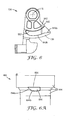
- FIG. 6 depicts a cross-sectional view of a handle 134 having a camming ramp 642 lifter engagement feature 640 disposed on cartridge lifter 138.
- camming ramp 642 comprises first ramp portion 642a and second ramp portion 642b.
- first ramp portion 642a has a greater slope than second ramp portion 642b.
- engagement of filter cartridge 460 to filter manifold 100 may be made by the steps set forth as follows. As handle 134 begins to rotate to allow cartridge lifter 138 to engage filter cartridge 460, first ramp portion 642a can engage camming lug 644 to quickly lift filter cartridge 460 from cartridge support shelf 106 until sump sealing member 101 sealingly couples filter cartridge 460 to filter manifold 100.
- cartridge feed port 470 is partially engaged with manifold feed port 130 and cartridge filtrate port is partially engaged with manifold filtrate port 132, with vent 133 creating a bypass past each port sealing member 471.
- camming lug 644 transitions to contact second ramp portion 642b, whereupon filter cartridge 460 is lifted more gradually.
- the more gradual lifting allows a more precise positioning of filter cartridge 460 in filter manifold 100 with respect to the angular position of rotary portion 218. It may be important, for example, that manifold feed port 130 remains blocked until each port sealing member 471 has moved beyond vent 133 to create a complete seal.
- First and second ramp portions 642a and 642b may comprise a linear profile or a curved profile.
- a camming ramp may alternatively be disposed on external cartridge surface 464.
- FIG. 6A shows a portion of a filter cartridge 460 having a camming lug 644 for engaging lifter engagement feature 640, wherein camming lug 644 is disposed on external cartridge surface 464.
- camming lug 644 comprises leading edge 644a and primary surface 644b.
- leading edge 644a may slidingly cooperate with first ramp portion 642a to assist with quickly lifting filter cartridge 460 from cartridge support shelf 106, while primary surface 644b may slidingly cooperate with second ramp portion 642b to more gradually and precisely engage filter cartridge 460 to filter manifold 100.
- a camming lug may alternatively be disposed on lifter engagement feature 640.
- engagement of camming ramp 642 with camming lug 644 comprises a two-step process. First, as handle 134 rotates counter-clockwise from a disengaged position into a service position as shown in FIG. 6 , first ramp portion 642a contacts leading edge 644a, thereby drawing filter cartridge 460 toward filter manifold 100. Second, as handle 134 continues to rotate, second ramp portion 642b contacts primary surface 644b, thereby continuing to draw filter cartridge 460 toward filter manifold 100. In embodiments where first ramp portion 642a has a greater slope than second ramp portion 642b, filter cartridge 460 is drawn toward filter manifold 100 at a greater rate during step one than during step two.
- such a two-step process can allow (i) a relatively quick sealing of filter cartridge 460 to filter manifold 100 during the first step, thereby helping to prevent any fluid from escaping filtration system 590 during filter cartridge installation, while (ii) allowing, during the second step, a more gradual and precise timewise interaction between rotary portion 218 and filter cartridge 460 as filter cartridge 460 is fully seated against filter manifold 100 and manifold feed port 130 is unblocked.
- Handle 134 further comprises a handle disengagement feature 652.
- handle disengagement feature 652 may comprise a camming surface positioned in a location opposing camming ramp 642 lifter engagement feature 640.
- Camming lug 644 on external cartridge surface 464 comprises a cartridge disengagement feature 654.
- cartridge disengagement feature 654 may comprise a camming surface positioned in a location opposing primary surface 644b. Handle disengagement feature 652 and cartridge disengagement feature 654 can cooperate to assist in removal of filter cartridge 460 from filter manifold 100 when handle 134 is rotated in a clockwise direction as shown in FIG. 6 .
- handle disengagement feature 652 contacts cartridge disengagement feature 654 to push filter cartridge 460 away from filter manifold 100.
- This combination of disengagement features can ease user removal of filter cartridge 460 from filter manifold 100 by using mechanical advantage gained by actuating handle 134 to assist in decoupling each port sealing member 471 from respective manifold feed port 130 and manifold filtrate port 132.
- Such assistance can be beneficial where, for example, sealing members such as o-rings have temporarily "set” due to compressed for extended periods of time, causing them to stick to the surface they are sealed against.
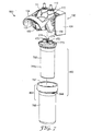
- FIG. 7 shows an exemplary embodiment of a filtration system 590 in a disassembled state, wherein filter cartridge 460 comprises disposable filter element 768 and rigid sump 766 having interior volume 767. At least a portion of disposable filter element 768 is positionable within interior volume 767. In some embodiments, rigid sump 766 is reused each time disposable filter element 768 is replaced. In such embodiments, a reduction in environmental waste can be realized as less material may be discarded upon filter disposable filter element 768 replacement.
- disposable filter element 768 comprises cartridge feed port 470, cartridge filtrate port 472, rotation key 274, and a filtration media surrounded by casing 768a having filter head 773 affixed to one end thereof.
- cartridge feed port 470, cartridge filtrate port 472, and rotation key 274 are disposed on filter head 773.
- Casing 768a comprises an impermeable material.
- casing 768a comprises a flexible impermeable material, for example, low-density polyethylene.
- filter head 773 comprises a relatively rigid material as compared to casing 768a.
- Filter head 773 may be constructed of any suitable rigid material. Examples of suitable materials include polypropylene, polystyrene, nylon, and various polyphenylene ether compounds.
- rigid sump 766 is configured to be a pressure vessel that is designed to withstand greater operating pressure than is casing 768a.
- Rigid sump 766 may be constructed of any suitable rigid material. Examples of suitable materials include polypropylene, polystyrene, nylon, and various polyphenylene ether compounds. It is also envisioned that, in applications requiring greater strength, for example, rigid sump 766 may be constructed of metals such as stainless steel and aluminum.
- casing 768a need not be capable of withstanding the same pressure as rigid sump 766, disposable filter element 768 can be constructed with much less material than would otherwise be necessary. Accordingly, less material is disposed of each time disposable filter element 768 is replaced. Casing 768a provides a further advantage of preventing interior volume 767 from becoming wetted with feed fluid. Accordingly, any required cleaning of rigid sump 766 can be reduced or eliminated.
- external cartridge surface 464 may be a part of either rigid sump 766 or disposable filter element 768. Typically, however, external cartridge surface 464 is a part of rigid sump 766.
- rotation key 274 is typically disposed on filter head 773. Accordingly, if an empty rigid sump 766 is placed onto filter manifold 100, rotation key 274 will not depress rotation lock 124 shown in FIG. 1A , and handle 134 will be prevented from rotating into the service position. Because handle 134 will not rotate into the service position, manifold feed port 130 shown in FIG. 1A will remain blocked. In such embodiments, filtration system 590 will only allow unblocking of manifold feed port 130 when a compatible disposable filter element 768 is installed in the rigid sump 766 before installation of filter cartridge 460 onto filter manifold 100.
- a user or service technician is prevented from mistakenly omitting disposable filter element 768 when re-installing rigid sump 766. Accordingly, in such embodiments, the user can be assured that filtration system 590 is performing a filtering function if rigid sump 766 is installed and handle 134 is in the service position.
Landscapes
- Chemical & Material Sciences (AREA)
- Chemical Kinetics & Catalysis (AREA)
- Separation Using Semi-Permeable Membranes (AREA)
- Filtration Of Liquid (AREA)
- Water Treatment By Sorption (AREA)
Description
- Water filtration systems are often employed in residential and commercial applications. Such systems are typically installed in a water supply and work to provide filtered water to faucets, drinking water dispensers, and the like. In some residential applications, a filtration system is installed underneath a countertop, for example, in a kitchen. In many instances, such systems have a homeowner changeable, disposable filter cartridge. When the service life of a disposable filter cartridge has expired, the homeowner must remove the spent filter cartridge and install a new filter cartridge. Where such systems are located underneath a countertop, it may be difficult for the homeowner to reach the system and perform the necessary installation steps. Often, such locations are cramped and available space, both for the system itself and for the homeowner to reach the system, is limited. After a new filter cartridge has been installed, the entire spent filter cartridge is typically disposed of.
- There is a continuing need for filtration systems that take up less space, are quick and simple to maintain, and contribute less environmental waste when spent filter cartridges are disposed of.
- The present disclosure relates generally to a filter manifold and filtration system that can reduce the time and effort necessary to service a filtration system. Filter cartridges according to the present disclosure can be installed with a single pull of a handle to pick up the filter cartridge and engage it to the filter manifold. The filter manifold and filtration system of the present disclosure may have a low-profile construction that can reduce the space occupied by a water filtration system. Further, because less material can be used, the present invention can reduce environmental waste associated with disposing of spent filter cartridges.
- Document
US 2005/167352 A1 is directed to a filter cartridge and a manifold for a water purification system. Downward pivoting motion of a manifold cup causes a pair of cam tracks to engage and carry cam pins along cam rails to carry the cartridge ports into flow engagement with manifold inlet and outlet fittings. - The present application discloses a filter manifold comprising a valve. The valve comprises a fixed portion, a rotary portion, and a rotation lock connected to the rotary portion. The manifold further comprises a manifold feed port and a manifold filtrate port. A handle is operatively connected to the rotary portion and comprises a cartridge lifter. In some embodiments, the cartridge lifter comprises a lifter engagement feature selected from the group consisting of a camming ramp and a camming lug. The handle is rotatable to a service position and a locked position, wherein, when the handle is in the locked position, rotation is prevented by the rotation lock and the manifold feed port is blocked by the valve.
- In one embodiment, the filter manifold further comprises a bracket, wherein the valve is held by the bracket, wherein the fixed portion is attached to the bracket.
- In one embodiment, the filter manifold further comprises a cartridge support shelf. The cartridge support shelf may be disposed on the bracket in a position below the cartridge lifter when the handle is in the service position. The cartridge support shelf may alternatively be a part of the fixed portion of the valve.
- In some embodiments, the rotation lock comprises a depressible member connected to the rotary portion of the valve and protruding through an aperture in the fixed portion of the valve. In one embodiment, the depressible member is depressible from a locking position to an unlocking position. In some embodiments, the depressible member protrudes through the aperture when in the locking position and is recessed within the fixed portion of the valve when in the unlocking position. In one embodiment, the depressible member is in the unlocking position when the handle is in the service position.
- In one embodiment, the rotary portion of the valve comprises a bypass channel fluidly connecting the manifold feed port to the manifold filtrate port when the handle is in the locked position. Where appropriate, the rotary portion of the valve comprises a two-part shell, the two-part shell having a first cylindrical portion and second cylindrical portion, each cylindrical portion comprising a connection end having a recess therein for locating the depressible member and a fluid connector for a portion of the bypass channel. The connection ends of the first and second cylindrical portions connect to one another with a bayonet connection to locate the depressible member and to fluidly connect the bypass channel.
- In some embodiments, the fixed portion of the valve comprises a longitudinal axis, a first end oriented along the longitudinal axis, and a second end opposing the first end. In such embodiments, a first axial extension of the rotary portion protrudes from the first end, and a second axial extension of the rotary portion protrudes from the second end. The handle may be affixed to the first and second axial extensions
- In some embodiments, a filter manifold further comprises a filter cartridge having a cartridge feed port, a cartridge filtrate port, and a rotation key, wherein the rotation key depresses the depressible member to the unlocking position. In one embodiment, the depressible member comprises a first distal surface and the rotation key comprises a protrusion from the filter cartridge. The protrusion may have a second distal surface, wherein the second distal surface contacts the first distal surface to depress the depressible member.
- The present application also discloses a filtration system comprising a filter manifold and a filter cartridge. In some embodiments, the filter manifold may comprise a bracket and a valve held by the bracket, wherein the valve comprises a fixed portion attached to the bracket and a rotary portion. In one embodiment, the bracket comprises a cartridge support shelf disposed on the bracket in a position below the cartridge lifter when the handle is in the service position. In some embodiments, the filter manifold is provided without a bracket. In such embodiments, the cartridge support shelf may be provided as a part of the fixed portion of the valve. In one embodiment, the filter manifold further comprises a manifold feed port and a manifold filtrate port. In some embodiments, a handle is operatively connected to the rotary portion and comprises a cartridge lifter having one of a camming ramp or a camming lug lifter engagement feature. The handle is rotatable to a service position and a disengaged position, wherein the manifold feed port is blocked by the valve when the handle is in the disengaged position.
- In disclosed filtration systems, the filter cartridge may comprise a cartridge feed port, a cartridge filtrate port, and an external cartridge surface having one of a camming lug or a camming ramp for engaging the lifter engagement feature.
- In some embodiments, the camming lug comprises a leading edge and a primary surface, wherein the leading edge contacts the camming ramp prior to the primary surface contacting the camming ramp.
- In one embodiment, the camming ramp comprises a first ramp portion and a second ramp portion, wherein the first ramp portion advances the camming lug toward the filter manifold at a greater rate than the second ramp portion. In one embodiment, the first ramp portion comprises a linear profile and the second ramp portion comprises a curved profile. In another embodiment, the first and second ramp portions each comprise a curved profile.
- The handle comprises a handle disengagement feature and the filter cartridge comprises a cartridge disengagement feature. The handle disengagement feature cooperates, as the handle rotates, with the cartridge disengagement feature to assist in pushing the filter cartridge away from the filter manifold during removal of the filter cartridge.
- In some embodiments of disclosed filtration systems, the filter cartridge comprises a rigid sump having an interior volume and a disposable filter element. At least a portion of the disposable filter element is positionable within the interior volume. In one embodiment, the external cartridge surface is on the rigid sump. In another embodiment, the external cartridge surface is on the disposable filter element.
- In one embodiment of disclosed filtration systems, the valve further comprises a rotation lock connected to the rotary portion. In such embodiments, rotation of the handle may be prevented by the rotation lock when the handle is in the disengaged position. In some embodiments, the rotation lock comprises a depressible member connected to the rotary portion of the valve and protruding through an aperture in the fixed portion of the valve. In one embodiment, the depressible member is depressible from a locking position to an unlocking position. In some embodiments, the filter cartridge further comprises a rotation key, wherein the rotation key depresses the depressible member to the unlocking position.
- The present application also discloses methods for assembling the filtration systems described above. In one embodiment, the method comprises the steps of (i) providing the filter cartridge below the filter manifold while the handle is in the disengaged position, (ii) rotating the handle into the service position, thereby causing the cartridge lifter to contact the camming ramp with the camming lug, thereby drawing the filter cartridge toward the filter manifold, (iii) engaging the cartridge feed port to the manifold feed port, (iv) engaging the cartridge filtrate port to the manifold filtrate port, and (v) actuating the valve to unblock the manifold feed port.
- Throughout the specification, reference is made to the appended drawings, where like reference numerals designate like elements, and wherein:
-
FIG. 1 is a perspective view of a filter manifold; -
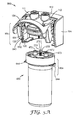
FIG. 1A is a bottom perspective view of the filter manifold ofFIG. 1 ; -
FIG. 2 is a cross-sectional view taken at 2-2 ofFIG. 1 of a portion of a filter manifold having a handle and valve in a locked position with a filter cartridge positioned below the filter manifold; -
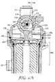
FIG. 2A is a partial cross-sectional view taken at 2A-2A ofFIG. 1 showing the assembly ofFIG. 2 with the filter cartridge fully installed onto the manifold and the handle and valve in a service position; -
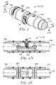
FIG. 3 is a perspective view of a rotary portion of a valve; -
FIG. 3A is a cross-sectional view taken at 3A-3A ofFIG. 3 of a rotary portion of a valve; -
FIG. 3B is a cross-sectional view taken at 3B-3B ofFIG. 3 of a rotary portion of a valve; -
FIG. 3C is an exploded view of a rotary portion of a valve; -
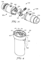
FIG. 4 is a perspective view of a filter cartridge in an assembled state; -
FIG. 5 is a perspective view of a filtration system with a filter cartridge installed and a handle in a service position; -
FIG. 5A shows a filtration system with the filter cartridge removed and the handle in a locked position; -
FIG. 6 is a cross-sectional view taken at 6-6 ofFIG. 5 of a handle having a camming ramp; -
FIG. 6A shows a camming lug on a filter cartridge; and -
FIG. 7 is a perspective view of a filtration system with the filter cartridge removed and the handle in a locked position, wherein the filter cartridge comprises a disposable filter element and a rigid sump. -
FIGS. 1 and 1A depict an exemplary embodiment of afilter manifold 100.Filter manifold 100 typically comprises abracket 104.Bracket 104 may comprise further mounting structure to enablefilter manifold 100 to be affixed to a wall or other suitable backing.Filter manifold 100 further comprises afeed water source 111, afiltrate outlet 112, avalve 110, and ahandle 134 having structure thereon for engaging compatible geometry on a filter cartridge, for example,filter cartridge 460, to draw the filter cartridge towardfilter manifold 100. InFIGS. 1 and 1A , handle 134 is shown in a locked, or disengaged, position.Valve 110 typically comprises a fixedportion 114 and arotary portion 218, as shown in greater detail inFIGS. 2 and2A . Handle 134 is operatively connected torotary portion 218 ofvalve 110. In one embodiment, handle 134 comprises a gripping portion that allows a user to actuate handle 134 with one hand and preferably with a single downward stroke. - In some embodiments,
filter manifold 100 is provided withoutbracket 104. In such embodiments, fixedportion 114 ofvalve 110 may be provided with mounting structure to allow direct mounting ofvalve 110 to a wall or other backing. Suitable mounting structure includes, for example, raised bosses having a bore therein for accepting a threaded fastener. Other suitable mounting structure includes, for example, male or female snap features for engaging a complimentary snap feature on a wall or other backing. - The various parts of
filter manifold 100 as described above and in later described embodiments may be constructed from any suitable material having adequate strength and manufacturability. Examples of suitable materials include polypropylene, polystyrene, nylon, and various polyphenylene ether compounds. It is also envisioned that, in applications requiring greater strength, for example, parts may be constructed of metals such as stainless steel and aluminum. - In some embodiments,
filter manifold 100 comprises at least onecartridge support shelf 106. Typically,cartridge support shelf 106 is affixed tobracket 104. In some embodiments, such as shown inFIGS. 1 and 1A ,bracket 104 comprises opposing sides, and onecartridge support shelf 106 is disposed on each opposing side ofbracket 104.Cartridge support shelf 106 is positioned to supportfilter cartridge 460 in a staging position prior to assembly or after disassembly offilter cartridge 460 fromfilter manifold 100. In some embodiments, the staging position is located to allowfilter cartridge 460 to rest in a position to cooperate withcartridge lifter 138 onhandle 134. In such embodiments, ashandle 134 is rotated,cartridge lifter 138 can engage a compatible feature onfilter cartridge 460, thereby liftingfilter cartridge 460 fromcartridge support shelf 106 and drawingfilter cartridge 460 towardfilter manifold 100.Cartridge support shelf 106 provides a convenient place to restfilter cartridge 460 and also helps ensure proper alignment offilter cartridge 460 for cooperation withcartridge lifter 138.Cartridge support shelf 106 can provide the further function of a hard stop forfilter cartridge 460 as it is being removed fromfilter manifold 100, thereby helping preventfilter cartridge 460 from falling or from otherwise ejecting fromfilter manifold 100 upon removal under operating pressure. - In embodiments where
filter manifold 100 is provided withoutbracket 104,cartridge support shelf 106 may be provided as a part of fixedportion 114 ofvalve 110. For example,cartridge support shelf 106 may be integrally molded on one or more protrusions projecting from fixedportion 114.Cartridge support shelf 106 may alternatively be provided as a discrete part that is fastened to fixedportion 114 by suitable fasteners. Examples of suitable fasteners include screws, snaps, rivets, adhesives, and the like. In embodiments wherecartridge support shelf 106 is provided as a part of fixedportion 114, it is envisioned thatcartridge support shelf 106 is positioned in substantially the same location relative to fixedportion 114 as is shown inFIG. 1 , whereincartridge support shelf 106 is shown as a part ofbracket 104. -
FIG. 1A depictsfilter manifold 100 ofFIG. 1 rotated to show the underside thereof. As shown, at least a portion of adepressible member 126 protrudes into anaperture 116 in fixedportion 114 ofvalve 110.Aperture 116 is flanked on either side bymanifold feed port 130 andmanifold filtrate port 132. In some embodiments,aperture 116 may be positioned to one side or the other of bothmanifold feed port 130 andmanifold filtrate port 132.Depressible member 126 andaperture 116 are discussed in greater detail with regard toFIGS. 2 and2A below. - In some embodiments, one or both of
manifold feed port 130 andmanifold filtrate port 132 comprise avent 133, as shown inFIG. 1A configured to cause a bypass past a seal on one or both of acartridge feed port 470 and acartridge filtrate port 472, both shown inFIG. 4 , as a filter cartridge is removed fromfilter manifold 100. In some embodiments,cartridge feed port 470 andcartridge filtrate port 472 each comprise aport sealing member 471, as shown inFIG. 4 , to sealingly couple thecartridge feed port 470 to themanifold feed port 130 and thecartridge filtrate port 472 to themanifold filtrate port 132.Port sealing member 471 may comprise, for example, an o-ring, a gasket, or an overmolded elastomeric seal. Vent 133 may comprise a series of vent features. Each vent feature may comprise a scalloped recess on an interior wall of either or both of themanifold feed port 130 andmanifold filtrate port 132. Each scalloped recess is configured to cause a bypass past aport sealing member 471 asfilter cartridge 460 is removed fromfilter manifold 100. Any pressurized fluid remaining infilter cartridge 460 can then escape throughvent 133 to a lower pressure region beforefilter cartridge 460 is completely removed fromfilter manifold 100. In some embodiments,filter cartridge 460 remains held bycartridge lifter 138 at the time a bypass is created and the pressurized fluid is vented. In such embodiments, vent 133 andcartridge lifter 138 work together to prevent rapid, uncontrolled disengagement of the filter cartridge fromfilter manifold 100. - In some embodiments, a
sump sealing member 101 is further provided on one offilter cartridge 460 orfilter manifold 100.Sump sealing member 101 sealingly couples filtercartridge 460 to filtermanifold 100, thereby isolating aninterior connection chamber 102 from an ambient environment.Sump sealing member 101 may comprise, for example, an o-ring, a gasket, or an overmolded elastomeric seal.Sump sealing member 101 is typically positioned to maintain isolation ofinterior connection chamber 102 during a pressurized fluid bypass throughvent 133. In such embodiments, any pressurized fluid that escapes throughvent 133 is contained withininterior connection chamber 102 prior to complete disengagement offilter cartridge 460 fromfilter manifold 100. -
FIGS. 2 and2A depict an exemplary embodiment of avalve 110 in both a locked position (FIG. 2 ) and an unlocked position (FIG. 2A ).Bracket 104 is omitted for clarity. The locked, or disengaged, position corresponds to a state wherefilter cartridge 460 shown inFIG. 4 is removed. The unlocked position corresponds to a state wherefilter cartridge 460 is installed.Valve 110 may comprise fixedportion 114 androtary portion 218.Fixed portion 114 typically comprises a body having a cylindrical bore having alongitudinal axis 115. As shown inFIGS. 2 and2A , feed water source 111 (along withfiltrate outlet 112, not shown) is typically affixed to fixedportion 114. In some embodiments, fixedportion 114 further comprisessump sealing member 101.Rotary portion 218 typically comprises a cylinder having alongitudinal axis 115a as shown inFIG. 3 .Fixed portion 114 androtary portion 218 are nested, androtary portion 218 rotates with respect to fixedportion 114.Manifold feed port 130 is blocked whenrotary portion 218 is in the locked position. Rotation ofrotary portion 218 to the unlocked position unblocksmanifold feed port 130. In some embodiments,rotary portion 218 is free to rotate throughout a limited arc when in the locked position. In one embodiment, the limited arc corresponds to an angular displacement ofrotary portion 218 of about 45 degrees. In another embodiment, the angular displacement is about 30 degrees. In a further embodiment, the angular displacement is about 15 degrees. Typically,manifold feed port 130 remains blocked during rotation through the limited arc. Allowing the handle to travel through the limited arc permits thecartridge lifter 138 to partially engagefilter cartridge 460 without unblockingmanifold feed port 130. This feature can ease service by helping to holdfilter cartridge 460 in place during installation and removal. In some embodiments, this feature works together withcartridge support shelf 106 to help holdfilter cartridge 460 in place during installation and removal. - As shown in
FIGS. 2 and2A , abypass channel 220 may be formed or otherwise disposed inrotary portion 218. In such embodiments,bypass channel 220 fluidly connectsfeed water source 111 to thefiltrate outlet 112 offilter manifold 100 whenrotary portion 218 is in the locked position. Whenrotary portion 218 is in the unlocked position,bypass channel 220 is moved out of fluid communication withfeed water source 111 andfiltrate outlet 112.Bypass channel 220 can allow a fluid to continue to flow throughfilter manifold 100 whenfilter cartridge 460 is removed, while fluid is directed throughfilter cartridge 460 whenfilter cartridge 460 is installed. - In some embodiments,
rotary portion 218 is prevented from rotating to the unlocked position byrotation lock 124.Rotation lock 124 may comprise adepressible member 126 extending through at least a portion ofaperture 116 in fixedportion 114. Interference betweendepressible member 126 and afirst wall 217 ofaperture 116 preventsrotary portion 218 from rotating beyond the limited arc. In some embodiments, thedepressible member 126 comprises a spring-loaded pin. In some embodiments,depressible member 126 comprises a solid pin portion having firstdistal surface 228 backed by a coil spring. It is envisioned that other resilient members may be used to back a solid pin portion ofdepressible member 126. It is also envisioned thatdepressible member 126 can be constructed entirely of, for example, a rubber or other resilient material.Depressible member 126 may alternatively comprise a coil spring. - In some embodiments,
depressible member 126 comprises a firstdistal surface 228 facing in a direction orthogonal tolongitudinal axis 115a ofrotary portion 218. Whendepressible member 126 is depressed to a sufficient extent,rotary portion 218 is free to rotate past the limited arc and pastfirst wall 217, whereupon firstdistal surface 228 ofdepressible member 126 slides through andpast aperture 116 and along an inner cylinder wall of fixedportion 114. Whenrotary portion 218 is rotated to the unlocked position,manifold feed port 130 is unblocked. In one embodiment, the maximum angular displacement ofrotary portion 218 in rotating from a locked position to an unlocked position is about 90 degrees. In another embodiment, the maximum angular displacement is about 120 degrees. In another embodiment, the maximum angular displacement is about 60 degrees. The maximum angular displacement may be chosen to provide the desired stroke length forhandle 134 to maximize ergonomic benefit for single-handed service offilter cartridge 460. - Typically,
rotation lock 124 is depressible by arotation key 274 onfilter cartridge 460, as shown inFIGS. 2 and2A . Whenfilter cartridge 460 is installed intofilter manifold 100,rotation key 274 depressesrotation lock 124, thereby allowingrotary portion 218 to rotate from the locked position to the unlocked position. In some embodiments,rotation key 274 comprises aprotrusion 276 having a seconddistal surface 278 thereon. In such embodiments, seconddistal surface 278 contacts firstdistal surface 228 to depressrotation lock 124. In one embodiment,rotation key 274 is disposed onfilter head 473 offilter cartridge 460. In some embodiments,rotation key 274 is positioned onfilter head 473 betweencartridge feed port 470 andcartridge filtrate port 472 shown inFIG. 4 . In some embodiments,rotation key 274 is offset fromcartridge feed port 470 andcartridge filtrate port 472 to further work as an alignment feature such thatfilter cartridge 460 may only be installed intofilter manifold 100 in a single orientation. -
FIGS. 3, 3A, 3B , and3C show an exemplary embodiment ofrotary portion 218 ofvalve 110. In some embodiments,rotary portion 218 comprises a two-part shell 322. Two-part shell 322 comprises firstcylindrical portion 322a and secondcylindrical portion 322b. Firstcylindrical portion 322a comprisesfeed channel 330a, and secondcylindrical portion 322b comprisesfiltrate channel 332a. In one embodiment, firstcylindrical portion 322a and secondcylindrical portion 322b each comprise a portion ofbypass channel 220 and afluid connector 322e for fluidly connecting the two portions ofbypass channel 220.Bypass channel 220 is configured to fluidly connectfeed water source 111 tofiltrate outlet 112. Firstcylindrical portion 322a and secondcylindrical portion 322b may each have aconnection end 322c comprising arecess 322d therein for locatingdepressible member 126. Alternatively,recess 322d may be formed in only of the firstcylindrical portion 322a or secondcylindrical portion 322b. Eachconnection end 322c may further comprise abayonet connection 322f. When firstcylindrical portion 322a and secondcylindrical portion 322b are connected to each other, in applicable embodiments,fluid connectors 322e fluidly connect the two portions ofbypass channel 220.Rotary portion 218 may be provided as two-part shell 322 instead of a single part in order to include internal features such asbypass channel 220. Absent a two-part construction, molding or machining of such internal features present difficult challenges, as would be understood by one skilled in the art. Applicants resolved the difficult challenges by providingrotary portion 218 as two-part shell 322 that may be manufactured more easily and at a lower cost than a single part. - In some embodiments,
rotary portion 218 comprises a firstaxial extension 318a and a secondaxial extension 318b configured to extend beyond respective first andsecond ends portion 114. In embodiments whererotary portion 218 comprises two-part shell 322, firstaxial extension 318a is disposed on firstcylindrical portion 322a and secondaxial extension 318b is disposed on secondcylindrical portion 322b. First and secondaxial extensions handle 134 to actuatevalve 110. In the context of the present application, Applicants define the term "operatively connected" to mean "connected in a way to perform a designated function." Accordingly, as used above, first and secondaxial extensions valve 110. For example, handle 134 and first and secondaxial extensions FIG. 3 , first and secondaxial extensions FIG. 6 , handle 134 may comprise two sides each comprising a cylindrical bore having a flat inner surface portion. Each bore onhandle 134 may be pressed over respective first and secondaxial extensions - In another embodiment, handle 134 and first and second
axial extensions axial extensions -
FIG. 4 depicts an exemplary embodiment of afilter cartridge 460. In some embodiments,filter cartridge 460 comprises acartridge feed port 470, acartridge filtrate port 472, arotation key 274, and a filtration media surrounded by a pressure vessel having afilter head 473 affixed to one end thereof. In one embodiment,cartridge feed port 470,cartridge filtrate port 472, androtation key 274 are disposed onfilter head 473. In some embodiments,cartridge feed port 470 andcartridge filtrate port 472 each comprise aport sealing member 471.Filter cartridge 460 comprises anexternal cartridge surface 464. In some embodiments, at least onecamming lug 644 or at least onecamming ramp 642 as shown inFIG. 6 is disposed onexternal cartridge surface 464. While the embodiment depicted inFIG. 4 shows a camming lug disposed nearfilter head 473, it is envisioned that a camming lug or camming ramp may be disposed in any location onexternal cartridge surface 464.Filter head 473 andexternal cartridge surface 464 may be constructed of any suitable rigid material. Examples of suitable materials include polypropylene, polystyrene, nylon, and various polyphenylene ether compounds. It is also envisioned that, in applications requiring greater strength, for example, one or both offilter head 473 andexternal cartridge surface 464 may be constructed of metals such as stainless steel and aluminum. -
Cartridge feed port 470 is fluidly connected to an upstream portion of the filtration media, whilecartridge filtrate port 472 is fluidly connected to a downstream portion of the filtration media. Accordingly, in typical embodiments, any fluid enteringfilter cartridge 460 throughcartridge feed port 470 must flow through the filtration media to reachcartridge filtrate port 472. Suitable filtration media include, for example, carbon blocks, pleated media, nonwovens, membranes, depth filtration media, and porous polymer blocks. - In some embodiments,
filter cartridge 460 is generally elliptical in cross-section, allowing it to consume less depth than, for example, a cylindrical filter cartridge. In such embodiments, the filtration media may also be provided with a generally elliptical cross-section. A corresponding cartridge mating portion offilter manifold 100 may also be provided with a generally elliptical cross section. In applications where a filtration system according to the present disclosure is mounted on a wall, such elliptical geometry allows the filtration system to protrude from the wall a lesser distance than would a comparable cylindrical geometry with the same filtration capacity. -
FIGS. 5 and5A depict an exemplary embodiment of afiltration system 590 in both a service state and a disassembled state. Typically,filtration system 590 comprises afilter manifold 100 and afilter cartridge 460. InFIG. 5 ,filter cartridge 460 is installed and handle 134 is in an unlocked, or service, position. InFIG. 5A ,filter cartridge 460 is removed and handle 134 is in a locked, or disengaged, position. In one embodiment,filter manifold 100 comprisesbracket 104, handle 134,valve 110,cartridge support shelf 106, amanifold feed port 130 as shown inFIG. 1A , amanifold filtrate port 132 as shown inFIG. 1A , afeed water source 111, and afiltrate outlet 112. As discussed above, in some embodiments,filter manifold 100 is provided withoutbracket 104. In such embodiments,cartridge support shelf 106 may be provided as a part of fixedportion 114, as discussed above. In some embodiments,filter manifold 100 comprisessump sealing member 101. In one embodiment,sump sealing member 101 is provided on fixedportion 114 ofvalve 110. Handle 134 further comprisescartridge lifter 138 having one of acamming ramp 642 orcamming lug 644lifter engagement feature 640. In one embodiment,filter cartridge 460 comprisesexternal cartridge surface 464,cartridge feed port 470,cartridge filtrate port 472,port sealing members 471,rotation key 274, and at least onecamming lug 644 orcamming ramp 642 for engaginglifter engagement feature 640. In some embodiments,rotation key 274 comprises aprotrusion 276 having seconddistal surface 278. - It is envisioned that
external cartridge surface 464 andcartridge lifter 138 comprise complementary engagement features. For example,lifter engagement feature 640 may comprise acamming ramp 642 andexternal cartridge surface 464 may comprise acamming lug 644. Similarly,lifter engagement feature 640 may comprise acamming lug 644 andexternal cartridge surface 464 may comprise acamming ramp 642. It is also envisioned that handle 134 may comprise more than onecartridge lifter 138, and that thecartridge lifters 138 may comprise the same or different types of lifter engagement features 640. For example, handle 134 may comprise two opposingcartridge lifters 138, one for each side offilter cartridge 460. Onecartridge lifter 138 may comprise acamming ramp 642, while an opposingcartridge lifter 138 may comprise acamming lug 644. In such embodiments,external cartridge surface 464 comprises acamming lug 644 corresponding to thecamming ramp 642lifter engagement feature 640 and acamming ramp 642 corresponding to thecamming lug 644lifter engagement feature 640. - In one embodiment,
filtration system 590 is assembled by (i) providingfilter cartridge 460 belowfilter manifold 100 whilehandle 134 is in the disengaged position, (ii)rotating handle 134 into the service position, thereby causingcartridge lifter 138 to contactcamming ramp 642 withcamming lug 644, thereby drawingfilter cartridge 460 towardfilter manifold 100, (iii) engagingcartridge feed port 470 tomanifold feed port 130, (iv) engagingcartridge filtrate port 472 to themanifold filtrate port 132, and (v) actuatingvalve 110 to unblockmanifold feed port 130. - The
filtration system 590 can be assembled by (i) restingfilter cartridge 460 in a staging position oncartridge support shelf 106 whilehandle 134 is in the disengaged position, (ii)rotating handle 134 into the service position, thereby causingcartridge lifter 138 to contactcamming ramp 642 withcamming lug 644 to liftfilter cartridge 460 off ofcartridge support shelf 106 and drawfilter cartridge 460 towardfilter manifold 100, (iii) engagingcartridge feed port 470 tomanifold feed port 130, (iv) engagingcartridge filtrate port 472 tomanifold filtrate port 132, and (v) actuatingvalve 110 to unblockmanifold feed port 130. - The
filtration system 590 can be assembled by (i) providingfilter cartridge 460 belowfilter manifold 100 whilehandle 134 is in the disengaged position, (ii) contactingrotation key 274 to rotation lock 124 as shown inFIG. 1A , (iii)rotating handle 134 into the service position, thereby causingcartridge lifter 138 to contactcamming ramp 642 withcamming lug 644 to drawfilter cartridge 460 towardfilter manifold 100, (iv) engagingcartridge feed port 470 tomanifold feed port 130, (v) engagingcartridge filtrate port 472 tomanifold filtrate port 132, and (vi) actuatingvalve 110 to unblockmanifold feed port 130. - The
filtration system 590 can be assembled by (i) providingfilter cartridge 460 belowfilter manifold 100 whilehandle 134 is in the disengaged position and whilebypass channel 220 fluidly connects afeed water source 111 and a filtrate outlet 512, (ii)rotating handle 134 into the service position, thereby causingcartridge lifter 138 to contactcamming ramp 642 withcamming lug 644, thereby drawingfilter cartridge 460 towardfilter manifold 100, (iii) engagingcartridge feed port 470 tomanifold feed port 130, (iv) engagingcartridge filtrate port 472 to themanifold filtrate port 132, (v) movingbypass channel 220 out of fluid connection with thefeed water source 111 and afiltrate outlet 112, and (vi) actuatingvalve 110 to unblockmanifold feed port 130. - It is to be understood that some steps described in the above methods need not be sequential. For example, in a typical embodiment, engaging
cartridge feed port 470 tomanifold feed port 130 as shown inFIG. 1A occurs substantially simultaneously with engagingcartridge filtrate port 472 tomanifold filtrate port 132 as shown inFIG. 1A . It is also to be understood that steps from the above-described methods are not exclusive to the embodiments in which they are described. For example, the step of restingfilter cartridge 460 in a staging position oncartridge support shelf 106 whilehandle 134 is in the disengaged position may be combined in the same method with contactingrotation key 274 torotation lock 124. Other method steps may be similarly combined. -
FIG. 6 depicts a cross-sectional view of ahandle 134 having acamming ramp 642lifter engagement feature 640 disposed oncartridge lifter 138. In some embodiments,camming ramp 642 comprisesfirst ramp portion 642a andsecond ramp portion 642b. In one embodiment,first ramp portion 642a has a greater slope thansecond ramp portion 642b. In such embodiments, engagement offilter cartridge 460 to filter manifold 100 may be made by the steps set forth as follows. Ashandle 134 begins to rotate to allowcartridge lifter 138 to engagefilter cartridge 460,first ramp portion 642a can engagecamming lug 644 to quickly liftfilter cartridge 460 fromcartridge support shelf 106 untilsump sealing member 101 sealingly couples filtercartridge 460 to filtermanifold 100. At such point in the engagement process,cartridge feed port 470 is partially engaged withmanifold feed port 130 and cartridge filtrate port is partially engaged withmanifold filtrate port 132, withvent 133 creating a bypass past eachport sealing member 471. Then, upon further rotation ofhandle 134,camming lug 644 transitions to contactsecond ramp portion 642b, whereuponfilter cartridge 460 is lifted more gradually. The more gradual lifting allows a more precise positioning offilter cartridge 460 infilter manifold 100 with respect to the angular position ofrotary portion 218. It may be important, for example, thatmanifold feed port 130 remains blocked until eachport sealing member 471 has moved beyondvent 133 to create a complete seal. After such seal is created, handle 134 continues to rotate, thereby allowingcamming lug 644 to continue to slide uponsecond ramp portion 642b untilfilter cartridge 460 is fully seated againstfilter manifold 100 andmanifold feed port 130 is unblocked. First andsecond ramp portions external cartridge surface 464. -
FIG. 6A shows a portion of afilter cartridge 460 having acamming lug 644 for engaginglifter engagement feature 640, whereincamming lug 644 is disposed onexternal cartridge surface 464. In some embodiments,camming lug 644 comprises leadingedge 644a andprimary surface 644b. In such embodiments, leadingedge 644a may slidingly cooperate withfirst ramp portion 642a to assist with quickly liftingfilter cartridge 460 fromcartridge support shelf 106, whileprimary surface 644b may slidingly cooperate withsecond ramp portion 642b to more gradually and precisely engagefilter cartridge 460 to filtermanifold 100. A camming lug may alternatively be disposed onlifter engagement feature 640. - In some embodiments, engagement of
camming ramp 642 withcamming lug 644 comprises a two-step process. First, ashandle 134 rotates counter-clockwise from a disengaged position into a service position as shown inFIG. 6 ,first ramp portion 642acontacts leading edge 644a, thereby drawingfilter cartridge 460 towardfilter manifold 100. Second, ashandle 134 continues to rotate,second ramp portion 642b contactsprimary surface 644b, thereby continuing to drawfilter cartridge 460 towardfilter manifold 100. In embodiments wherefirst ramp portion 642a has a greater slope thansecond ramp portion 642b,filter cartridge 460 is drawn towardfilter manifold 100 at a greater rate during step one than during step two. Along with the benefits described above, such a two-step process can allow (i) a relatively quick sealing offilter cartridge 460 to filter manifold 100 during the first step, thereby helping to prevent any fluid from escapingfiltration system 590 during filter cartridge installation, while (ii) allowing, during the second step, a more gradual and precise timewise interaction betweenrotary portion 218 andfilter cartridge 460 asfilter cartridge 460 is fully seated againstfilter manifold 100 andmanifold feed port 130 is unblocked. - Handle 134 further comprises a
handle disengagement feature 652. As shown inFIG. 6 , handledisengagement feature 652 may comprise a camming surface positioned in a location opposingcamming ramp 642lifter engagement feature 640.Camming lug 644 onexternal cartridge surface 464 comprises acartridge disengagement feature 654. As shown inFIG. 6A ,cartridge disengagement feature 654 may comprise a camming surface positioned in a location opposingprimary surface 644b.Handle disengagement feature 652 andcartridge disengagement feature 654 can cooperate to assist in removal offilter cartridge 460 fromfilter manifold 100 whenhandle 134 is rotated in a clockwise direction as shown inFIG. 6 . Ashandle 134 is rotated in a clockwise direction, handle disengagement feature 652 contactscartridge disengagement feature 654 to pushfilter cartridge 460 away fromfilter manifold 100. This combination of disengagement features can ease user removal offilter cartridge 460 fromfilter manifold 100 by using mechanical advantage gained by actuatinghandle 134 to assist in decoupling eachport sealing member 471 from respectivemanifold feed port 130 andmanifold filtrate port 132. Such assistance can be beneficial where, for example, sealing members such as o-rings have temporarily "set" due to compressed for extended periods of time, causing them to stick to the surface they are sealed against. -
FIG. 7 shows an exemplary embodiment of afiltration system 590 in a disassembled state, whereinfilter cartridge 460 comprisesdisposable filter element 768 andrigid sump 766 havinginterior volume 767. At least a portion ofdisposable filter element 768 is positionable withininterior volume 767. In some embodiments,rigid sump 766 is reused each timedisposable filter element 768 is replaced. In such embodiments, a reduction in environmental waste can be realized as less material may be discarded upon filterdisposable filter element 768 replacement. - In some embodiments,
disposable filter element 768 comprisescartridge feed port 470,cartridge filtrate port 472,rotation key 274, and a filtration media surrounded by casing 768a havingfilter head 773 affixed to one end thereof. In one embodiment,cartridge feed port 470,cartridge filtrate port 472, androtation key 274 are disposed onfilter head 773.Casing 768a comprises an impermeable material. In some embodiments,casing 768a comprises a flexible impermeable material, for example, low-density polyethylene. Typically,filter head 773 comprises a relatively rigid material as compared tocasing 768a.Filter head 773 may be constructed of any suitable rigid material. Examples of suitable materials include polypropylene, polystyrene, nylon, and various polyphenylene ether compounds. - In some embodiments,
rigid sump 766 is configured to be a pressure vessel that is designed to withstand greater operating pressure than is casing 768a.Rigid sump 766 may be constructed of any suitable rigid material. Examples of suitable materials include polypropylene, polystyrene, nylon, and various polyphenylene ether compounds. It is also envisioned that, in applications requiring greater strength, for example,rigid sump 766 may be constructed of metals such as stainless steel and aluminum. When a typical embodiment offiltration system 590 is assembled and placed under operating pressure,casing 768a bears against a sidewall ofinterior volume 767 ofrigid sump 766. Becausecasing 768a need not be capable of withstanding the same pressure asrigid sump 766,disposable filter element 768 can be constructed with much less material than would otherwise be necessary. Accordingly, less material is disposed of each timedisposable filter element 768 is replaced.Casing 768a provides a further advantage of preventinginterior volume 767 from becoming wetted with feed fluid. Accordingly, any required cleaning ofrigid sump 766 can be reduced or eliminated. - It is envisioned that
external cartridge surface 464 may be a part of eitherrigid sump 766 ordisposable filter element 768. Typically, however,external cartridge surface 464 is a part ofrigid sump 766. - In embodiments where
filter cartridge 460 comprisesdisposable filter element 768 andrigid sump 766,rotation key 274 is typically disposed onfilter head 773. Accordingly, if an emptyrigid sump 766 is placed ontofilter manifold 100,rotation key 274 will not depressrotation lock 124 shown inFIG. 1A , and handle 134 will be prevented from rotating into the service position. Becausehandle 134 will not rotate into the service position,manifold feed port 130 shown inFIG. 1A will remain blocked. In such embodiments,filtration system 590 will only allow unblocking ofmanifold feed port 130 when a compatibledisposable filter element 768 is installed in therigid sump 766 before installation offilter cartridge 460 ontofilter manifold 100. In such embodiments, a user or service technician is prevented from mistakenly omittingdisposable filter element 768 when re-installingrigid sump 766. Accordingly, in such embodiments, the user can be assured thatfiltration system 590 is performing a filtering function ifrigid sump 766 is installed and handle 134 is in the service position.
Claims (15)
- A filtration system comprising:a filter manifold (100) and a filter cartridge (460);the filter manifold (100) comprising
a valve (110) comprising a fixed portion (114) and a rotary portion (218);
a manifold feed port (130) and a manifold filtrate port (132);
a handle (134) operatively connected to the rotary portion (218), the handle (134) comprising a cartridge lifter (138) having one of a camming ramp or a camming lug lifter engagement feature (640), the handle (134) being rotatable to a service position and a disengaged position, wherein the manifold feed port (130) is blocked by the valve when the handle is in the disengaged position;the filter cartridge (460) comprising
a cartridge feed port (470), a cartridge filtrate port (472), and an external cartridge surface (464) having one of a camming lug (644) or a camming ramp (642) for engaging the lifter engagement feature (640)
characterised in that the handle (134) has a handle disengagement feature and the cartridge has a cartridge disengagement feature. - The filtration system of claim 1 wherein the lifter engagement feature (640) comprises a camming ramp and the external cartridge surface comprises a camming lug.
- The filtration system of claim 1 wherein the lifter engagement feature (640) comprises a camming lug and the external cartridge surface comprises a camming ramp.
- The filtration system of claim 1 wherein the camming lug comprises a leading edge and a primary surface, wherein the leading edge contacts the camming ramp prior to the primary surface contacting the camming ramp.
- The filtration system of claim 1 wherein the camming ramp comprises a first ramp portion and a second ramp portion, wherein the first ramp portion advances the camming lug toward the filter manifold at a greater rate than the second ramp portion.
- The filtration system of claim 5 wherein the first ramp portion comprises a linear profile and the second ramp portion comprises a curved profile.
- The filtration system of claim 6 wherein the first and second ramp portions each comprise a curved profile.
- The filtration system of any of claims 1-7 wherein the filter manifold (100) further comprises a bracket (104), wherein the valve (110) is held by the bracket (104), wherein the fixed portion (114) is attached to the bracket (104), wherein the bracket (104) comprises a cartridge support shelf (106) disposed on the bracket (104) in a position below the cartridge lifter (138) when the handle (134) is in the service position.
- The filtration system of any of claims 1-8 wherein the filter cartridge (460) comprises a rigid sump (766) having an interior volume (767) and a disposable filter element (768), at least a portion of the disposable filter element (768) being positionable within the interior volume (767).
- The filtration system of claim 9 wherein the external cartridge surface (464) is on the rigid sump (766).
- The filtration system of claim 9 wherein the external cartridge surface (464) is on the disposable filter element (768).
- The filtration system of claim 1 wherein the valve (110) further comprises a rotation lock (124) connected to the rotary portion (218) and wherein, when the handle (134) is in the disengaged position, rotation is prevented by the rotation lock (124).
- The filtration system of claim 12 wherein the rotation lock (124) comprises a depressible member (126) connected to the rotary portion (218) of the valve (110) and protruding through an aperture (116) in the fixed portion (114) of the valve (110) and the depressible member (126) is depressible from a locking position to an unlocking position.
- The filtration system of claim 13 wherein the filter cartridge (460) further comprises a rotation key (274), wherein the rotation key (274) depresses the depressible member (126) to the unlocking position.
- A method of assembling the filtration system of any of claims 1-8 comprising the steps of:providing the filter cartridge (460) below the filter manifold (100) while the handle (134) is in the disengaged position;rotating the handle (134) into the service position, thereby causing the cartridge lifter (138) to contact the camming ramp with the camming lug, thereby drawing the filter cartridge (460) toward the filter manifold (100);engaging the cartridge feed port (470) to the manifold feed port (130);engaging the cartridge filtrate port (472) to the manifold filtrate port (132); andactuating the valve (100) to unblock the manifold feed port (130).
Applications Claiming Priority (2)
| Application Number | Priority Date | Filing Date | Title |
|---|---|---|---|
| US9473708P | 2008-09-05 | 2008-09-05 | |
| PCT/US2009/055643 WO2010027989A2 (en) | 2008-09-05 | 2009-09-02 | Filtration system |
Publications (3)
| Publication Number | Publication Date |
|---|---|
| EP2355914A2 EP2355914A2 (en) | 2011-08-17 |
| EP2355914A4 EP2355914A4 (en) | 2013-01-02 |
| EP2355914B1 true EP2355914B1 (en) | 2014-06-11 |
Family
ID=41797814
Family Applications (1)
| Application Number | Title | Priority Date | Filing Date |
|---|---|---|---|
| EP09812126.2A Not-in-force EP2355914B1 (en) | 2008-09-05 | 2009-09-02 | Filtration system |
Country Status (7)
| Country | Link |
|---|---|
| US (1) | US9044699B2 (en) |
| EP (1) | EP2355914B1 (en) |
| JP (1) | JP5536774B2 (en) |
| KR (1) | KR101614566B1 (en) |
| CN (1) | CN102176955B (en) |
| BR (1) | BRPI0913488A2 (en) |
| WO (1) | WO2010027989A2 (en) |
Families Citing this family (55)
| Publication number | Priority date | Publication date | Assignee | Title |
|---|---|---|---|---|
| CN101198390B (en) | 2005-05-16 | 2010-10-06 | 3M创新有限公司 | Column Valve Manifold Interconnect Construction for Filtration Systems |
| EP2355914B1 (en) | 2008-09-05 | 2014-06-11 | 3M Innovative Properties Company | Filtration system |
| US10843108B2 (en) * | 2011-06-21 | 2020-11-24 | Kinetico Incorporated | Water treatment system |
| KR101318423B1 (en) * | 2011-06-24 | 2013-10-15 | 위니맥스 주식회사 | Water filter assembly and refrigerator and water purifier having the same |
| US20130206654A1 (en) * | 2011-09-07 | 2013-08-15 | Electrolytic Ozone Inc. | Hub and removable cartridge for producing and delivering ozonated water |
| WO2013134916A1 (en) * | 2012-03-12 | 2013-09-19 | 深圳市兴日生实业有限公司 | Out-of-vat liquid filter for ensuring reliable connection of water pipe connector |
| US8945383B2 (en) | 2012-03-16 | 2015-02-03 | Kx Technologies Llc | Filtration system |
| US8951415B2 (en) | 2012-03-16 | 2015-02-10 | Kx Technologies Llc | Filtration system |
| JP2013230410A (en) * | 2012-04-27 | 2013-11-14 | Sharp Corp | Liquid filter |
| US9789424B2 (en) | 2013-06-26 | 2017-10-17 | Pentair Residential Filtration, Llc | Water filtration system and method |
| US9492770B2 (en) | 2013-10-31 | 2016-11-15 | Pall Corporation | Filters |
| US9527021B2 (en) | 2013-10-31 | 2016-12-27 | Pall Corporation | Filter manifold |
| USD722132S1 (en) | 2013-10-31 | 2015-02-03 | Pall Corporation | Filter |
| US9757670B2 (en) * | 2013-10-31 | 2017-09-12 | Pall Corporation | Methods for moving a filter along a manifold assembly; filter arrangements including a filter and a manifold assembly; and filters |
| US9713782B2 (en) | 2013-11-11 | 2017-07-25 | Pall Corporation | Filters and filter arrangements which include a filter and a manifold assembly |
| USD755344S1 (en) | 2014-06-26 | 2016-05-03 | Pentair Residential Filtration, Llc | Filter cartridge |
| CN106039816B (en) | 2015-04-09 | 2020-07-03 | 碧然德有限公司 | Device for forming liquid treatment apparatus and liquid treatment apparatus |
| US20170095757A1 (en) | 2015-05-27 | 2017-04-06 | Flow Control LLC | Cartridge Accumulator |
| JP6946195B2 (en) | 2015-05-27 | 2021-10-06 | フロー コントロール リミティド ライアビリティ カンパニー | Cartridge pump |
| CA2998354C (en) | 2015-09-14 | 2023-06-13 | Flow Control Llc. | Cartridge accumulator |
| KR101788965B1 (en) * | 2016-03-22 | 2017-10-20 | 엘지전자 주식회사 | water purifing apparatus refrigerator |
| JP6802371B2 (en) | 2016-10-20 | 2020-12-16 | イー・エム・デイー・ミリポア・コーポレイシヨン | Valve protection and tube management device |
| WO2018153435A1 (en) * | 2017-02-21 | 2018-08-30 | Mahle International Gmbh | Fuel filter device for an internal combustion engine |
| US20180318738A1 (en) * | 2017-05-04 | 2018-11-08 | Haier Us Appliance Solutions, Inc. | Enhanced filter installation |
| WO2019016167A1 (en) * | 2017-07-17 | 2019-01-24 | Castrol Limited | Replaceable fluid container with removable manifold |
| PL234666B1 (en) * | 2018-04-26 | 2020-03-31 | Aquael Janusz Jankiewicz Spolka Z Ograniczona Odpowiedzialnoscia | Water filter for an aquarium |
| CN108644424B (en) * | 2018-06-26 | 2019-10-29 | 浙江沁园水处理科技有限公司 | A kind of independent bivalve module and its water purifier |
| CN108644423B (en) * | 2018-06-26 | 2020-01-03 | 浙江沁园水处理科技有限公司 | Bivalve module and water purifier with wash function |
| CN108644425B (en) * | 2018-06-26 | 2019-10-29 | 浙江沁园水处理科技有限公司 | A kind of inlet valve and its water purifier with pressure-reduction module |
| CN108895164B (en) * | 2018-06-26 | 2020-01-24 | 浙江沁园水处理科技有限公司 | Water inlet valve and water purifier thereof |
| CN108644426B (en) * | 2018-06-26 | 2019-10-29 | 浙江沁园水处理科技有限公司 | A kind of series connection bivalve module and its water purifier |
| CN108889023B (en) * | 2018-06-26 | 2021-02-12 | 浙江沁园水处理科技有限公司 | Water purifier with filter flask capable of being quickly disassembled and assembled |
| CN108980403B (en) * | 2018-06-26 | 2019-12-13 | 浙江沁园水处理科技有限公司 | Water inlet valve with flow meter and water purifier thereof |
| CN108644411B (en) * | 2018-06-26 | 2020-01-03 | 浙江沁园水处理科技有限公司 | Flushing valve and water purifier thereof |
| CN108644427B (en) * | 2018-06-26 | 2019-10-29 | 浙江沁园水处理科技有限公司 | A kind of integral type bivalve module and its water purifier |
| DE102018129752A1 (en) * | 2018-11-26 | 2020-05-28 | Franke Technology And Trademark Ltd | FILTER DEVICE FOR DRINKING WATER FILTERING |
| KR102052554B1 (en) * | 2019-01-31 | 2019-12-05 | 주식회사 교원 | Filter connector and water purifier including the same |
| KR102177297B1 (en) * | 2019-02-28 | 2020-11-10 | 청호나이스 주식회사 | Connecting structure for filter and water purifier having the same |
| US11660554B2 (en) * | 2019-11-11 | 2023-05-30 | Qingdao Ecopure Filler Co., Ltd. | Appliance water filter cartridge |
| JP2023519455A (en) * | 2020-03-27 | 2023-05-11 | エスピーエックス フロー テクノロジー ユーエスエイ インコーポレイテッド | Filter assembly and filter material |
| CN111285419B (en) * | 2020-03-31 | 2024-11-05 | 珠海格力电器股份有限公司 | Drinking water purification equipment and filter mechanism |
| CN113828047B (en) | 2020-06-08 | 2023-02-24 | 帕尔公司 | Manifold assembly and method of use |
| IL283156B2 (en) * | 2020-06-08 | 2024-11-01 | Pall Corp | Manifold assembly and method of using it |
| WO2022020783A1 (en) * | 2020-07-24 | 2022-01-27 | 3Oe Scientific, LLC | Aqueous ozone sanitizing system controller and methods |
| JP7690295B2 (en) * | 2021-02-05 | 2025-06-10 | オルガノ株式会社 | Cartridge mounting structure and cartridge |
| WO2022229927A1 (en) | 2021-04-30 | 2022-11-03 | Whirlpool Corporation | Filter assembly |
| CN116764321A (en) * | 2021-11-29 | 2023-09-19 | 南京菡束环保设备有限公司 | Filter element mounting structure |
| US12215041B2 (en) * | 2022-07-27 | 2025-02-04 | Kemflo International Co., Ltd. | Water filter with quick release device |
| TWI811172B (en) * | 2022-12-30 | 2023-08-01 | 凱舟濾材股份有限公司 | Filter head cover |
| KR20250019952A (en) * | 2023-08-02 | 2025-02-11 | 엘지전자 주식회사 | water treatment apparatus |
| KR20250019953A (en) * | 2023-08-02 | 2025-02-11 | 엘지전자 주식회사 | water treatment apparatus |
| CN117287577B (en) * | 2023-09-28 | 2025-09-09 | 巨翊科技(上海)有限公司 | Axial rotation locking sterile connection device, butt connector, system and connection method |
| KR20250088345A (en) * | 2023-12-08 | 2025-06-17 | 엘지전자 주식회사 | water purifier |
| KR20260050848A (en) * | 2024-10-08 | 2026-04-15 | 엘지전자 주식회사 | A filter for purified water supply device |
| KR20260050873A (en) * | 2024-10-08 | 2026-04-15 | 엘지전자 주식회사 | A filter for purified water supply device |
Family Cites Families (60)
| Publication number | Priority date | Publication date | Assignee | Title |
|---|---|---|---|---|
| US1688326A (en) | 1925-09-16 | 1928-10-23 | Zenith Carburateur Soc Du | Filter |
| US2857128A (en) | 1956-10-18 | 1958-10-21 | Stern Daniel | Safety shutoff coupling |
| US3399776A (en) | 1965-09-02 | 1968-09-03 | Robert R. Knuth | Detachable snap-on filter for a hydraulic system |
| US3742970A (en) | 1970-02-13 | 1973-07-03 | Pall Corp | Flow-sensitive sensing and shut-off device |
| US3643692A (en) | 1970-09-28 | 1972-02-22 | Paul L Traylor | Valve |
| US3684100A (en) | 1971-04-05 | 1972-08-15 | Sam Close | Filter assembly and disposable filter element therefor |
| CH537546A (en) | 1971-04-06 | 1973-05-31 | Saffin Von Corpon Paul | Robinet mélangeur |
| BE791684A (en) | 1971-11-22 | 1973-03-16 | Ogden Hubert S | REMOVABLE FILTER CARTRIDGE |
| JPS5129619A (en) | 1974-09-02 | 1976-03-13 | Matsushita Electric Industrial Co Ltd | Nainenkikanno haikigasujokasochi |
| US3926187A (en) | 1974-12-19 | 1975-12-16 | Jose J Iglesias | Urological bladder evacuator |
| US4108207A (en) | 1977-04-13 | 1978-08-22 | The United States Of America As Represented By The United States Department Of Energy | Multiple-port valve |
| DE3126507A1 (en) * | 1981-07-04 | 1983-01-20 | Surculus AG, Vaduz | "ARMATURE" |
| JPS5867510A (en) | 1981-10-20 | 1983-04-22 | Nippon Denso Co Ltd | Automobile ventilator |
| JPS5867510U (en) * | 1981-10-30 | 1983-05-09 | 三菱農機株式会社 | Oil filter installation structure |
| JPS58116008U (en) * | 1982-01-28 | 1983-08-08 | 三菱農機株式会社 | oil filter |
| US4469131A (en) | 1982-07-12 | 1984-09-04 | Traylor Paul L | Spool valve |
| DE3520139A1 (en) | 1985-06-05 | 1986-12-11 | Joachim 7252 Weil der Stadt Wolf | FILTER DEVICE |
| DE3640531C1 (en) | 1986-11-27 | 1987-09-03 | Bayerische Motoren Werke Ag | Filter arrangement for cleaning liquid operating materials, especially the lubricating oil of internal combustion engines |
| US4979530A (en) | 1987-12-24 | 1990-12-25 | Ameri-Can Brass Faucet Inc. | Modular valve assembly |
| GB2216030B (en) | 1988-05-11 | 1991-10-09 | Joachim Wolf | A filter |
| GB2216028B (en) | 1988-05-16 | 1991-09-25 | Joachim Wolf | A filter manifold |
| IL87280A (en) | 1988-08-01 | 1991-01-31 | Dolev Moshe | Quick-disconnect hose coupling device |
| US5152321A (en) | 1991-10-07 | 1992-10-06 | Ecowater Systems, Inc. | Bypass valve |
| DE4135867A1 (en) | 1991-10-31 | 1993-05-06 | Alfred Teves Gmbh, 6000 Frankfurt, De | CUFF RETURN VALVE |
| US5230812A (en) | 1992-07-29 | 1993-07-27 | Williams Richard T | Pressure vessel |
| US5461948A (en) | 1992-08-27 | 1995-10-31 | Perrero, Jr.; Thomas | Socket type tool for removing oil filter cartridge |
| US5389260A (en) * | 1993-04-02 | 1995-02-14 | Clack Corporation | Brine seal for tubular filter |
| US5397462A (en) | 1993-08-24 | 1995-03-14 | Matsushita Electric Industrial Co., Ltd. | Filter with laterally removable element and valve means |
| US5445734A (en) | 1994-11-18 | 1995-08-29 | Chen; Ching-Wen | Water filter |
| US5882511A (en) | 1996-10-30 | 1999-03-16 | Fil-Tech Corporation | Filter apparatus with coupling and latch mechanism |
| US5919362A (en) | 1997-04-28 | 1999-07-06 | Cuno, Inc. | Expandable encapsulated filter cartridge assembly |
| US5931196A (en) | 1998-04-29 | 1999-08-03 | United States Filter Corporation | Bypass valve |
| US6579455B1 (en) | 1999-09-09 | 2003-06-17 | Pti Advanced Filtration | Filter and valve apparatus |
| US6953526B1 (en) | 2000-03-22 | 2005-10-11 | Cuno Incorporated | Filter assembly |
| US6949189B2 (en) | 2000-04-20 | 2005-09-27 | Cuno Incorporated | Keyed filter assembly |
| US6458269B1 (en) | 2000-04-20 | 2002-10-01 | Cuno Incorporated | Keyed filter assembly |
| US7407148B2 (en) | 2000-04-20 | 2008-08-05 | 3M Innovative Properties Company | Rotary valve assembly for fluid filtration system |
| US6457698B2 (en) | 2000-06-16 | 2002-10-01 | United States Filter Corporation | Bypass valve |
| JP3514724B2 (en) | 2000-11-29 | 2004-03-31 | 日東工器株式会社 | Pipe fittings |
| ITPD20010179A1 (en) | 2001-07-17 | 2003-01-17 | Askoll Holding Srl | PIPE FITTING GROUP WITH SAFETY LOCK FOR EXTERNAL FILTERS FOR AQUARIUMS. |
| US20030019819A1 (en) | 2001-07-30 | 2003-01-30 | Karl Fritze | Hot disconnect replaceable water filter assembly |
| US6632355B2 (en) | 2001-07-30 | 2003-10-14 | Pentapure Incorporated | Low spillage replaceable water filter assembly |
| US6857670B2 (en) | 2001-12-05 | 2005-02-22 | Cuno Incorporated | Plastic tube joint |
| US7638042B2 (en) | 2002-02-15 | 2009-12-29 | 3M Innovative Properties Company | System for monitoring the performance of fluid treatment cartridges |
| JP4234938B2 (en) * | 2002-02-28 | 2009-03-04 | インテグリス・インコーポレーテッド | Connector device for filter cartridge |
| JP4125051B2 (en) * | 2002-06-20 | 2008-07-23 | インテグリス・インコーポレーテッド | Seal structure of connector device |
| JP4011986B2 (en) * | 2002-06-21 | 2007-11-21 | クリタック株式会社 | Water purification cartridge mounting device |
| JP3829117B2 (en) | 2002-12-27 | 2006-10-04 | 日東工器株式会社 | Pipe fitting |
| US7000894B2 (en) | 2003-04-25 | 2006-02-21 | Pur Water Purification Products, Inc. | Fluidic cartridges and end pieces thereof |
| US7147773B2 (en) | 2003-04-25 | 2006-12-12 | Whirlpool Corporation | Refrigerator with treated water |
| US20050167352A1 (en) * | 2004-02-03 | 2005-08-04 | Oasis Corporation | Filter cartridge and manifold for a water purification system |
| US20060032806A1 (en) | 2004-08-16 | 2006-02-16 | Parker Mark A | Apparatus to filter water |
| CN101198390B (en) * | 2005-05-16 | 2010-10-06 | 3M创新有限公司 | Column Valve Manifold Interconnect Construction for Filtration Systems |
| US7651070B2 (en) * | 2006-01-19 | 2010-01-26 | Clean & Clear Corporation | Canter element controlled combination manifold, valve and filter module system |
| KR100772889B1 (en) * | 2006-04-18 | 2007-11-02 | 주식회사 위닉스 | Water filter, water filter assembly connector and water purifier installed |
| US20080000820A1 (en) * | 2006-06-30 | 2008-01-03 | Mitchell Alan J | Water Filter Cartridge and Valve with Autobypass Feature |
| US20080156711A1 (en) | 2006-12-29 | 2008-07-03 | Vitan Craig R | Water filter assembly and filter cartridge for use therewith |
| KR100870572B1 (en) | 2007-02-28 | 2008-11-27 | 주식회사 영우워터라인 | Filter Assembly for Water Purifier with Rotating Connector |
| KR100930665B1 (en) | 2008-01-28 | 2009-12-09 | 앨트웰텍 주식회사 | Rotary Detachable Filter Supporter |
| EP2355914B1 (en) | 2008-09-05 | 2014-06-11 | 3M Innovative Properties Company | Filtration system |
-
2009
- 2009-09-02 EP EP09812126.2A patent/EP2355914B1/en not_active Not-in-force
- 2009-09-02 CN CN200980139908.8A patent/CN102176955B/en not_active Expired - Fee Related
- 2009-09-02 JP JP2011526139A patent/JP5536774B2/en not_active Expired - Fee Related
- 2009-09-02 BR BRPI0913488A patent/BRPI0913488A2/en not_active IP Right Cessation
- 2009-09-02 US US13/062,008 patent/US9044699B2/en not_active Expired - Fee Related
- 2009-09-02 WO PCT/US2009/055643 patent/WO2010027989A2/en not_active Ceased
- 2009-09-02 KR KR1020117007568A patent/KR101614566B1/en not_active Expired - Fee Related
Also Published As
| Publication number | Publication date |
|---|---|
| EP2355914A4 (en) | 2013-01-02 |
| CN102176955B (en) | 2014-03-12 |
| US9044699B2 (en) | 2015-06-02 |
| EP2355914A2 (en) | 2011-08-17 |
| CN102176955A (en) | 2011-09-07 |
| BRPI0913488A2 (en) | 2017-05-30 |
| WO2010027989A2 (en) | 2010-03-11 |
| US20110247974A1 (en) | 2011-10-13 |
| WO2010027989A3 (en) | 2010-05-14 |
| JP5536774B2 (en) | 2014-07-02 |
| JP2012501832A (en) | 2012-01-26 |
| KR20110053380A (en) | 2011-05-20 |
| KR101614566B1 (en) | 2016-04-21 |
Similar Documents
| Publication | Publication Date | Title |
|---|---|---|
| US9044699B2 (en) | Filtration system | |
| US12311291B2 (en) | Water filtration system and method | |
| EP2340884B1 (en) | Filter assembly with floating key lock | |
| US7871517B2 (en) | Filter device | |
| EP1817093B1 (en) | Fuel filter assembly | |
| EP1904209B1 (en) | Fluid filtration system | |
| US10874959B2 (en) | Filter insert and a filter arrangement | |
| EP2806961B1 (en) | Filter apparatus with ejection arrangement | |
| EP2373394B1 (en) | Fluid interconnect | |
| EP2135661B1 (en) | Filter Element and Filter Assembly including Locking Mechanism | |
| US10518944B2 (en) | Drinking vessel lid assembly | |
| CN112642207B (en) | Water purifier | |
| WO2007117959A1 (en) | Fluid filter element and bypass adaptor | |
| EP3441123B1 (en) | A spin-on fluid treatment device and methods | |
| EP2600932A1 (en) | Shutoff valves for fluid conduit connectors | |
| CN111757776B (en) | Air filter easy to maintain | |
| CN211435343U (en) | Water purifier convenient to dismouting | |
| GB2543620A (en) | System for connecting a liquid treatment cartridge to a cartridge seat | |
| CN118950306A (en) | A fluid product dispenser | |
| CN212214833U (en) | Water purifying equipment | |
| JP2002192150A (en) | Device for fitting water purifier | |
| CN223995517U (en) | Filter device and filter element | |
| HK1159545B (en) | Filter assembly with floating key lock |
Legal Events
| Date | Code | Title | Description |
|---|---|---|---|
| PUAI | Public reference made under article 153(3) epc to a published international application that has entered the european phase |
Free format text: ORIGINAL CODE: 0009012 |
|
| 17P | Request for examination filed |
Effective date: 20110401 |
|
| AK | Designated contracting states |
Kind code of ref document: A2 Designated state(s): AT BE BG CH CY CZ DE DK EE ES FI FR GB GR HR HU IE IS IT LI LT LU LV MC MK MT NL NO PL PT RO SE SI SK SM TR |
|
| DAX | Request for extension of the european patent (deleted) | ||
| A4 | Supplementary search report drawn up and despatched |
Effective date: 20121130 |
|
| RIC1 | Information provided on ipc code assigned before grant |
Ipc: B01D 35/30 20060101AFI20121126BHEP Ipc: B01D 27/08 20060101ALI20121126BHEP |
|
| GRAP | Despatch of communication of intention to grant a patent |
Free format text: ORIGINAL CODE: EPIDOSNIGR1 |
|
| INTG | Intention to grant announced |
Effective date: 20140121 |
|
| GRAS | Grant fee paid |
Free format text: ORIGINAL CODE: EPIDOSNIGR3 |
|
| GRAA | (expected) grant |
Free format text: ORIGINAL CODE: 0009210 |
|
| AK | Designated contracting states |
Kind code of ref document: B1 Designated state(s): AT BE BG CH CY CZ DE DK EE ES FI FR GB GR HR HU IE IS IT LI LT LU LV MC MK MT NL NO PL PT RO SE SI SK SM TR |
|
| REG | Reference to a national code |
Ref country code: GB Ref legal event code: FG4D |
|
| REG | Reference to a national code |
Ref country code: CH Ref legal event code: EP |
|
| REG | Reference to a national code |
Ref country code: IE Ref legal event code: FG4D |
|
| REG | Reference to a national code |
Ref country code: AT Ref legal event code: REF Ref document number: 671952 Country of ref document: AT Kind code of ref document: T Effective date: 20140715 |
|
| REG | Reference to a national code |
Ref country code: DE Ref legal event code: R096 Ref document number: 602009024674 Country of ref document: DE Effective date: 20140724 |
|
| PG25 | Lapsed in a contracting state [announced via postgrant information from national office to epo] |
Ref country code: LT Free format text: LAPSE BECAUSE OF FAILURE TO SUBMIT A TRANSLATION OF THE DESCRIPTION OR TO PAY THE FEE WITHIN THE PRESCRIBED TIME-LIMIT Effective date: 20140611 Ref country code: FI Free format text: LAPSE BECAUSE OF FAILURE TO SUBMIT A TRANSLATION OF THE DESCRIPTION OR TO PAY THE FEE WITHIN THE PRESCRIBED TIME-LIMIT Effective date: 20140611 Ref country code: GR Free format text: LAPSE BECAUSE OF FAILURE TO SUBMIT A TRANSLATION OF THE DESCRIPTION OR TO PAY THE FEE WITHIN THE PRESCRIBED TIME-LIMIT Effective date: 20140912 Ref country code: NO Free format text: LAPSE BECAUSE OF FAILURE TO SUBMIT A TRANSLATION OF THE DESCRIPTION OR TO PAY THE FEE WITHIN THE PRESCRIBED TIME-LIMIT Effective date: 20140911 |
|
| REG | Reference to a national code |
Ref country code: NL Ref legal event code: VDEP Effective date: 20140611 |
|
| REG | Reference to a national code |
Ref country code: AT Ref legal event code: MK05 Ref document number: 671952 Country of ref document: AT Kind code of ref document: T Effective date: 20140611 |
|
| REG | Reference to a national code |
Ref country code: LT Ref legal event code: MG4D |
|
| PG25 | Lapsed in a contracting state [announced via postgrant information from national office to epo] |
Ref country code: SE Free format text: LAPSE BECAUSE OF FAILURE TO SUBMIT A TRANSLATION OF THE DESCRIPTION OR TO PAY THE FEE WITHIN THE PRESCRIBED TIME-LIMIT Effective date: 20140611 Ref country code: HR Free format text: LAPSE BECAUSE OF FAILURE TO SUBMIT A TRANSLATION OF THE DESCRIPTION OR TO PAY THE FEE WITHIN THE PRESCRIBED TIME-LIMIT Effective date: 20140611 Ref country code: LV Free format text: LAPSE BECAUSE OF FAILURE TO SUBMIT A TRANSLATION OF THE DESCRIPTION OR TO PAY THE FEE WITHIN THE PRESCRIBED TIME-LIMIT Effective date: 20140611 |
|
| PGFP | Annual fee paid to national office [announced via postgrant information from national office to epo] |
Ref country code: GB Payment date: 20140910 Year of fee payment: 6 |
|
| PG25 | Lapsed in a contracting state [announced via postgrant information from national office to epo] |
Ref country code: PT Free format text: LAPSE BECAUSE OF FAILURE TO SUBMIT A TRANSLATION OF THE DESCRIPTION OR TO PAY THE FEE WITHIN THE PRESCRIBED TIME-LIMIT Effective date: 20141013 Ref country code: CZ Free format text: LAPSE BECAUSE OF FAILURE TO SUBMIT A TRANSLATION OF THE DESCRIPTION OR TO PAY THE FEE WITHIN THE PRESCRIBED TIME-LIMIT Effective date: 20140611 Ref country code: EE Free format text: LAPSE BECAUSE OF FAILURE TO SUBMIT A TRANSLATION OF THE DESCRIPTION OR TO PAY THE FEE WITHIN THE PRESCRIBED TIME-LIMIT Effective date: 20140611 Ref country code: ES Free format text: LAPSE BECAUSE OF FAILURE TO SUBMIT A TRANSLATION OF THE DESCRIPTION OR TO PAY THE FEE WITHIN THE PRESCRIBED TIME-LIMIT Effective date: 20140611 Ref country code: SK Free format text: LAPSE BECAUSE OF FAILURE TO SUBMIT A TRANSLATION OF THE DESCRIPTION OR TO PAY THE FEE WITHIN THE PRESCRIBED TIME-LIMIT Effective date: 20140611 Ref country code: RO Free format text: LAPSE BECAUSE OF FAILURE TO SUBMIT A TRANSLATION OF THE DESCRIPTION OR TO PAY THE FEE WITHIN THE PRESCRIBED TIME-LIMIT Effective date: 20140611 |
|
| PG25 | Lapsed in a contracting state [announced via postgrant information from national office to epo] |
Ref country code: AT Free format text: LAPSE BECAUSE OF FAILURE TO SUBMIT A TRANSLATION OF THE DESCRIPTION OR TO PAY THE FEE WITHIN THE PRESCRIBED TIME-LIMIT Effective date: 20140611 Ref country code: PL Free format text: LAPSE BECAUSE OF FAILURE TO SUBMIT A TRANSLATION OF THE DESCRIPTION OR TO PAY THE FEE WITHIN THE PRESCRIBED TIME-LIMIT Effective date: 20140611 Ref country code: IS Free format text: LAPSE BECAUSE OF FAILURE TO SUBMIT A TRANSLATION OF THE DESCRIPTION OR TO PAY THE FEE WITHIN THE PRESCRIBED TIME-LIMIT Effective date: 20141011 Ref country code: NL Free format text: LAPSE BECAUSE OF FAILURE TO SUBMIT A TRANSLATION OF THE DESCRIPTION OR TO PAY THE FEE WITHIN THE PRESCRIBED TIME-LIMIT Effective date: 20140611 |
|
| REG | Reference to a national code |
Ref country code: DE Ref legal event code: R097 Ref document number: 602009024674 Country of ref document: DE |
|
| PLBE | No opposition filed within time limit |
Free format text: ORIGINAL CODE: 0009261 |
|
| STAA | Information on the status of an ep patent application or granted ep patent |
Free format text: STATUS: NO OPPOSITION FILED WITHIN TIME LIMIT |
|
| PG25 | Lapsed in a contracting state [announced via postgrant information from national office to epo] |
Ref country code: LU Free format text: LAPSE BECAUSE OF FAILURE TO SUBMIT A TRANSLATION OF THE DESCRIPTION OR TO PAY THE FEE WITHIN THE PRESCRIBED TIME-LIMIT Effective date: 20140902 Ref country code: IT Free format text: LAPSE BECAUSE OF FAILURE TO SUBMIT A TRANSLATION OF THE DESCRIPTION OR TO PAY THE FEE WITHIN THE PRESCRIBED TIME-LIMIT Effective date: 20140611 Ref country code: MC Free format text: LAPSE BECAUSE OF FAILURE TO SUBMIT A TRANSLATION OF THE DESCRIPTION OR TO PAY THE FEE WITHIN THE PRESCRIBED TIME-LIMIT Effective date: 20140611 Ref country code: DK Free format text: LAPSE BECAUSE OF FAILURE TO SUBMIT A TRANSLATION OF THE DESCRIPTION OR TO PAY THE FEE WITHIN THE PRESCRIBED TIME-LIMIT Effective date: 20140611 |
|
| REG | Reference to a national code |
Ref country code: CH Ref legal event code: PL |
|
| 26N | No opposition filed |
Effective date: 20150312 |
|
| REG | Reference to a national code |
Ref country code: IE Ref legal event code: MM4A |
|
| REG | Reference to a national code |
Ref country code: DE Ref legal event code: R097 Ref document number: 602009024674 Country of ref document: DE Effective date: 20150312 |
|
| REG | Reference to a national code |
Ref country code: FR Ref legal event code: ST Effective date: 20150529 |
|
| PG25 | Lapsed in a contracting state [announced via postgrant information from national office to epo] |
Ref country code: LI Free format text: LAPSE BECAUSE OF NON-PAYMENT OF DUE FEES Effective date: 20140930 Ref country code: CH Free format text: LAPSE BECAUSE OF NON-PAYMENT OF DUE FEES Effective date: 20140930 Ref country code: SI Free format text: LAPSE BECAUSE OF FAILURE TO SUBMIT A TRANSLATION OF THE DESCRIPTION OR TO PAY THE FEE WITHIN THE PRESCRIBED TIME-LIMIT Effective date: 20140611 |
|
| PG25 | Lapsed in a contracting state [announced via postgrant information from national office to epo] |
Ref country code: IE Free format text: LAPSE BECAUSE OF NON-PAYMENT OF DUE FEES Effective date: 20140902 Ref country code: FR Free format text: LAPSE BECAUSE OF NON-PAYMENT OF DUE FEES Effective date: 20140930 |
|
| PG25 | Lapsed in a contracting state [announced via postgrant information from national office to epo] |
Ref country code: SM Free format text: LAPSE BECAUSE OF FAILURE TO SUBMIT A TRANSLATION OF THE DESCRIPTION OR TO PAY THE FEE WITHIN THE PRESCRIBED TIME-LIMIT Effective date: 20140611 |
|
| GBPC | Gb: european patent ceased through non-payment of renewal fee |
Effective date: 20150902 |
|
| PG25 | Lapsed in a contracting state [announced via postgrant information from national office to epo] |
Ref country code: CY Free format text: LAPSE BECAUSE OF FAILURE TO SUBMIT A TRANSLATION OF THE DESCRIPTION OR TO PAY THE FEE WITHIN THE PRESCRIBED TIME-LIMIT Effective date: 20140611 Ref country code: BG Free format text: LAPSE BECAUSE OF FAILURE TO SUBMIT A TRANSLATION OF THE DESCRIPTION OR TO PAY THE FEE WITHIN THE PRESCRIBED TIME-LIMIT Effective date: 20140611 Ref country code: MT Free format text: LAPSE BECAUSE OF FAILURE TO SUBMIT A TRANSLATION OF THE DESCRIPTION OR TO PAY THE FEE WITHIN THE PRESCRIBED TIME-LIMIT Effective date: 20140611 |
|
| PG25 | Lapsed in a contracting state [announced via postgrant information from national office to epo] |
Ref country code: TR Free format text: LAPSE BECAUSE OF FAILURE TO SUBMIT A TRANSLATION OF THE DESCRIPTION OR TO PAY THE FEE WITHIN THE PRESCRIBED TIME-LIMIT Effective date: 20140611 Ref country code: GB Free format text: LAPSE BECAUSE OF NON-PAYMENT OF DUE FEES Effective date: 20150902 Ref country code: HU Free format text: LAPSE BECAUSE OF FAILURE TO SUBMIT A TRANSLATION OF THE DESCRIPTION OR TO PAY THE FEE WITHIN THE PRESCRIBED TIME-LIMIT; INVALID AB INITIO Effective date: 20090902 Ref country code: BE Free format text: LAPSE BECAUSE OF FAILURE TO SUBMIT A TRANSLATION OF THE DESCRIPTION OR TO PAY THE FEE WITHIN THE PRESCRIBED TIME-LIMIT Effective date: 20140611 |
|
| PGFP | Annual fee paid to national office [announced via postgrant information from national office to epo] |
Ref country code: DE Payment date: 20160831 Year of fee payment: 8 |
|
| REG | Reference to a national code |
Ref country code: DE Ref legal event code: R119 Ref document number: 602009024674 Country of ref document: DE |
|
| PG25 | Lapsed in a contracting state [announced via postgrant information from national office to epo] |
Ref country code: MK Free format text: LAPSE BECAUSE OF FAILURE TO SUBMIT A TRANSLATION OF THE DESCRIPTION OR TO PAY THE FEE WITHIN THE PRESCRIBED TIME-LIMIT Effective date: 20140611 |
|
| PG25 | Lapsed in a contracting state [announced via postgrant information from national office to epo] |
Ref country code: DE Free format text: LAPSE BECAUSE OF NON-PAYMENT OF DUE FEES Effective date: 20180404 |