EP2355640A2 - Information processing terminal - Google Patents
Information processing terminal Download PDFInfo
- Publication number
- EP2355640A2 EP2355640A2 EP10173809A EP10173809A EP2355640A2 EP 2355640 A2 EP2355640 A2 EP 2355640A2 EP 10173809 A EP10173809 A EP 10173809A EP 10173809 A EP10173809 A EP 10173809A EP 2355640 A2 EP2355640 A2 EP 2355640A2
- Authority
- EP
- European Patent Office
- Prior art keywords
- space
- terminal
- housing
- partition wall
- cooling fan
- Prior art date
- Legal status (The legal status is an assumption and is not a legal conclusion. Google has not performed a legal analysis and makes no representation as to the accuracy of the status listed.)
- Withdrawn
Links
Images


Classifications
-
- H—ELECTRICITY
- H05—ELECTRIC TECHNIQUES NOT OTHERWISE PROVIDED FOR
- H05K—PRINTED CIRCUITS; CASINGS OR CONSTRUCTIONAL DETAILS OF ELECTRIC APPARATUS; MANUFACTURE OF ASSEMBLAGES OF ELECTRICAL COMPONENTS
- H05K7/00—Constructional details common to different types of electric apparatus
- H05K7/20—Modifications to facilitate cooling, ventilating, or heating
- H05K7/20009—Modifications to facilitate cooling, ventilating, or heating using a gaseous coolant in electronic enclosures
- H05K7/20136—Forced ventilation, e.g. by fans
- H05K7/20145—Means for directing air flow, e.g. ducts, deflectors, plenum or guides
-
- G—PHYSICS
- G06—COMPUTING OR CALCULATING; COUNTING
- G06F—ELECTRIC DIGITAL DATA PROCESSING
- G06F1/00—Details not covered by groups G06F3/00 - G06F13/00 and G06F21/00
- G06F1/16—Constructional details or arrangements
- G06F1/20—Cooling means
-
- H—ELECTRICITY
- H05—ELECTRIC TECHNIQUES NOT OTHERWISE PROVIDED FOR
- H05K—PRINTED CIRCUITS; CASINGS OR CONSTRUCTIONAL DETAILS OF ELECTRIC APPARATUS; MANUFACTURE OF ASSEMBLAGES OF ELECTRICAL COMPONENTS
- H05K7/00—Constructional details common to different types of electric apparatus
- H05K7/20—Modifications to facilitate cooling, ventilating, or heating
- H05K7/20009—Modifications to facilitate cooling, ventilating, or heating using a gaseous coolant in electronic enclosures
- H05K7/20136—Forced ventilation, e.g. by fans
- H05K7/20172—Fan mounting or fan specifications
Definitions
- Embodiments described herein relate generally to an information processing terminal that increases cooling efficiency and work efficiency in replacing a mother board.
- An information processing terminal such as a personal computer or a POS terminal includes a mother board and a power supply in a housing case.
- An information processing terminal includes a mother board disposed at a lower portion of the housing and a power supply disposed above the mother board.
- a support member such as a pillar, etc., is necessary to support the power supply due to its own weight.
- such an information processing terminal entails a problem in that the power supply and the support member should be detached or removed to replace the mother board, thereby resulting in reduced work efficiency.
- the information processing device includes a housing which is divided into two internal spaces of an upper space and a lower space to arrange the mother board and the power supply respectively.
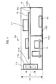
- FIG 1 is a front cross-sectional view of an information processing terminal according to a first embodiment.
- FIG. 2 is a perspective view of an information processing terminal according to the first embodiment with an upper cover of the information processing terminal removed.
- FIG. 3 is a perspective view of an information processing terminal according to the first embodiment with an upper cover and a mother board of the information processing terminal removed.
- FIG. 4 is a front cross-sectional view of an information processing terminal according to a second embodiment.
- an information processing terminal includes a partition wall dividing an inner room of a housing into a first space and a second space; a support member subdiving the second space into a third space and a fourth space with a ventilation path defined between the third space and fourth space.
- the support member is further configured to support the partition wall.
- the information processing terminal further includes a power supply disposed in the third space.
- the information processing terminal includes a mother board configured to allow a processing unit to be mounted thereon in the first space, and a cooling fan having a blade that extends across the first space and the second space defined by the partition wall.
- FIG 1 is a front cross-sectional view of an information processing terminal 10 according to a first embodiment.
- the information processing terminal 10 includes, in a housing 12, a mother board 13 configured to mount a processing unit (e.g., CPU 17) and a memory thereon, a power supply 14 configured to supply electric power to the mother board 13, a hard disk drive 15 that serves as a large-capacity storage, and a cooling fan 11 configured to cool the mother board 13 and the power supply 14.
- the information processing terminal 10 includes a computer, a personal computer, a POS terminal.
- the information processing terminal 10 includes the power supply 14 and the hard disk drive 15 on or above the base plate 12A.
- a support member 12C is provided on the base plate 12A to support the mother board 13.
- the housing 12 includes a support projection 12B to mount the mother board 13.
- the mother board 13 serves as a partition wall for dividing an inner room of the housing into a first space and a second space that are an upper space and a lower space, respectively.
- the mother board 13 serving as a partition wall functions to divide the flow of air generated by the cooling fan 11 into two air streams.
- the mother board 13 has an edge which is not in contact with the housing 12.
- the mother board 13 allows the CPU 17 to be mounted thereon in the first space of the housing 12.
- the support member 12C serves to subdivide the lower space, which is the second space out of the two internal spaces defined by the mother board 13, into a third space and a fourth space with a ventilation path defined between the third space and fourth space.
- the power supply 14 is installed in the third space and does not have a separate casing, to thereby improve cooling efficiency.
- the mother board 13 is supported by the support member 12C and the support projection 12B.
- the mother board 13 is disposed above the power supply 14.
- an upper cover of the hosing 12 is removed and then the mother board 13 is detached from the housing without detaching the power supply 14.
- the cooling fan 11 (e.g., one cooling fan) is provided at a side wall of the housing 12.
- the cooling fan 11 is constructed in such a way that a rotation center 11B of a rotating blade 11A thereof is flush with the mother board 13 or is positioned higher than the mother board 13 that serves as a partition wall. This structure increases cooling efficiency of the CPU 17 of the mother board 13.
- the cooling fan 11 is constructed in such a way that the rotating blade 11A thereof is disposed across the first space and the second space defined by the mother board 13.
- the diameter ⁇ 1 of the rotating blade 11A of the cooling fan 11 is set, e.g., to be greater than a half of the height of the housing 12. This is because as the diameter of the rotating blade 11A is increased, the cooling efficiency is improved and sound is reduced.
- FIG. 2 is a perspective view of an information processing terminal according to the first embodiment with an upper cover of the information processing terminal 10 removed.
- the flow of air is introduced into the housing 12 in the direction as indicated by an arrow "X1," i.e., from a second side wall of the housing 12 opposite a first side wall thereof on which the cooling fan 11 is mounted, so that it cools a cooling fin 13A of the CPU 17 and is discharged outside of the housing 12 by the cooling fan 11.
- FIG. 3 is a perspective view of an information processing terminal according to the first embodiment with an upper cover and a mother board of the information processing terminal 10 removed.
- the support member 12C is shown by a dotted line.
- the lower second space defined by the mother board 13 is subdivided into the third space and the fourth space by the support member 12C.
- the flow of air is divided into a first air stream indicated by an arrow "X2" and a second air stream indicated by an arrow "X3.”
- the first air stream is introduced from a rear side of the housing 12, and cools the hard disk drive 15 and then the power supply 14. Then, the first air stream is discharged outside of the housing 12 through the cooling fan 11 as indicated by an arrow "X4.”
- the second air stream is introduced from the rear side of the housing 12, and cools the power supply 14. Then, the second air stream is discharged outside of the housing 12 through the cooling fan 11 as indicated by an arrow "X4.”
- the support member 12C supports the mother board 13, and contributes to forming the air flow for cooling the hard disk drive 15 and the power supply 14.
- the support member 12C can be formed in any shape as long as it can support the mother board 13.
- the support member 12C is in the shape of a wall (e.g., a plate) or in the shape of a pillar.
- the information processing terminal 10 includes the power supply 14 disposed on the base plate 12A of the housing 12, and the mother board 13 disposed above the power supply 14 and configured to divide the inner room of the housing into two spaces.
- the information processing terminal 10 further includes the support member 12C configured to subdivide the lower space defined by the mother board 13 into the third space and the fourth space with the ventilation path defined therebetween, and support the mother board 13.
- the information processing terminal 10 further includes the cooling fan 11 having a rotating blade 11A that extends across the first space and the second space defined by the mother board 13.
- the information processing terminal 10 provides the advantages of reducing the number of steps to replace the mother board 13, and cooling both the mother board 13 and the power supply 14 using one cooling fan 11.
- FIG. 4 is a front cross-sectional view of an information processing terminal 10 according to a second embodiment.
- the information processing terminal 10 includes, in a housing 12, a mother board 13 configured to mount a processing unit (e.g., CPU 17) and a memory thereon, a partition wall 16 configured to mount the mother board 13 thereon, a power supply 14 configured to supply electric power to the mother board 13, a hard disk drive 15 that serves as a large-capacity storage, and a cooling fan 11 configured to cool the mother board 13 and the power supply 14.
- the information processing terminal 10 includes a computer, a personal computer, a POS terminal.
- the information processing terminal 10 includes the power supply 14 and the hard disk drive 15 supported on or above the base plate 12A.
- a support member 12C is provided on the base plate 12A to support the partition wall 16.
- the housing 12 includes a support projection 12B to mount the partition wall 16.
- the partition wall 16 divides an inner room of the housing 12 into a first space and a second space that are an upper space and a lower space, respectively.
- the partition wall 16 functions to divide the flow of air generated by the cooling fan 11 into two air streams.
- the partition wall 16 has an edge which is not in contact with the housing 12.
- the mother board 13 allows the CPU 17 to be mounted thereon in the first space of the housing 12.
- the support member 12C serves to subdivide the lower space, which is the second space out of the two internal spaces defined by the partition wall 16, into a third space and a fourth space with a ventilation path defined therebetween.
- the power supply 14 is installed in the third space and does not have a separate casing, to thereby improve cooling efficiency.
- the partition wall 16 is supported by the support member 12C and the support projection 12B.
- the partition wall 16 allows the mother board 13 to be mounted thereon.
- the mother board 13 is fixedly engaged with the partition wall 16 by means of an engagement member such as a screw.
- the mother board 13 is disposed above the power supply 14. If the mother board 13 is replaced with a new one, an upper cover of the housing 12 is removed and then the mother board 13 is detached from the housing 12 without detaching the power supply 14.
- the cooling fan 11 (e.g., one cooling fan) is located at a side wall of the housing 12.
- the cooling fan 11 is constructed in such a way that a rotation center 11B of a rotating blade 11A thereof is flush with the partition wall 16 or is positioned higher than the partition wall 16. This structure increases cooling efficiency of the CPU 17 of the mother board 13.
- the cooling fan 11 is constructed in such a way that the rotating blade 11A thereof is disposed across the first space and the second space defined by the partition wall 16.
- the diameter ⁇ 1 of the rotating blade 11A of the cooling fan 11 is set, e.g., to be greater than a half of the height of the housing 12. This is because as the diameter of the rotating blade 11A is increased, the cooling efficiency is improved and sound is reduced.
- the support member 12C can be formed in any shape as long as it can support the partition wall 16.
- the support member 12C is in the shape of a wall (i.e., a plate) or in the shape of a pillar.
- the information processing terminal 10 includes the power supply 14 disposed on the base plate 12A of the housing 12, and the partition wall 16 disposed above the power supply 14 and configured to divide the inner room of the housing into two spaces.
- the information processing terminal 10 further includes the support member 12C configured to subdivide the lower space defined by the partition wall 16 into the third space and the fourth space with the ventilation path defined therebetween, and support the partition wall 16.
- the information processing terminal 10 further includes the cooling fan 11 having a rotating blade 11A that is disposed across the first space and the second space defined by the partition wall 16.
- the inventive information processing terminal 10 has an advantageous effect in that although the size of the mother board 13 is small, it is possible to cool both the mother board 13 and the power supply 14 by using one cooling fan 11.
Landscapes
- Engineering & Computer Science (AREA)
- Microelectronics & Electronic Packaging (AREA)
- Physics & Mathematics (AREA)
- Thermal Sciences (AREA)
- Theoretical Computer Science (AREA)
- Human Computer Interaction (AREA)
- General Engineering & Computer Science (AREA)
- General Physics & Mathematics (AREA)
- Cooling Or The Like Of Electrical Apparatus (AREA)
Abstract
Description
- Embodiments described herein relate generally to an information processing terminal that increases cooling efficiency and work efficiency in replacing a mother board.
- An information processing terminal such as a personal computer or a POS terminal includes a mother board and a power supply in a housing case. An information processing terminal includes a mother board disposed at a lower portion of the housing and a power supply disposed above the mother board. A support member such as a pillar, etc., is necessary to support the power supply due to its own weight. Thus, such an information processing terminal entails a problem in that the power supply and the support member should be detached or removed to replace the mother board, thereby resulting in reduced work efficiency.
- In this regard, there has been proposed a technique in which the information processing device includes a housing which is divided into two internal spaces of an upper space and a lower space to arrange the mother board and the power supply respectively.
- However, the above technique involves a shortcoming in that since separate cooling fans are required to be mounted at the upper and lower spaces, respectively, a total of two cooling fans are required, thereby leading to an increase in the manufacturing cost.
-
FIG 1 is a front cross-sectional view of an information processing terminal according to a first embodiment. -
FIG. 2 is a perspective view of an information processing terminal according to the first embodiment with an upper cover of the information processing terminal removed. -
FIG. 3 is a perspective view of an information processing terminal according to the first embodiment with an upper cover and a mother board of the information processing terminal removed. -
FIG. 4 is a front cross-sectional view of an information processing terminal according to a second embodiment. - According to one embodiment, an information processing terminal includes a partition wall dividing an inner room of a housing into a first space and a second space; a support member subdiving the second space into a third space and a fourth space with a ventilation path defined between the third space and fourth space. The support member is further configured to support the partition wall. The information processing terminal further includes a power supply disposed in the third space. Further, the information processing terminal includes a mother board configured to allow a processing unit to be mounted thereon in the first space, and a cooling fan having a blade that extends across the first space and the second space defined by the partition wall.
- Embodiments of an information processing terminal will now be described in detail with reference to the accompanying drawings.
-
FIG 1 is a front cross-sectional view of aninformation processing terminal 10 according to a first embodiment. As shown inFIG. 1 , theinformation processing terminal 10 includes, in ahousing 12, amother board 13 configured to mount a processing unit (e.g., CPU 17) and a memory thereon, apower supply 14 configured to supply electric power to themother board 13, ahard disk drive 15 that serves as a large-capacity storage, and acooling fan 11 configured to cool themother board 13 and thepower supply 14. Herein, theinformation processing terminal 10 includes a computer, a personal computer, a POS terminal. - The
information processing terminal 10 includes thepower supply 14 and thehard disk drive 15 on or above thebase plate 12A. Asupport member 12C is provided on thebase plate 12A to support themother board 13. Thehousing 12 includes asupport projection 12B to mount themother board 13. - The
mother board 13 serves as a partition wall for dividing an inner room of the housing into a first space and a second space that are an upper space and a lower space, respectively. Themother board 13 serving as a partition wall functions to divide the flow of air generated by thecooling fan 11 into two air streams. Themother board 13 has an edge which is not in contact with thehousing 12. Themother board 13 allows theCPU 17 to be mounted thereon in the first space of thehousing 12. - The
support member 12C serves to subdivide the lower space, which is the second space out of the two internal spaces defined by themother board 13, into a third space and a fourth space with a ventilation path defined between the third space and fourth space. - The
power supply 14 is installed in the third space and does not have a separate casing, to thereby improve cooling efficiency. - The
mother board 13 is supported by thesupport member 12C and thesupport projection 12B. Themother board 13 is disposed above thepower supply 14. When replacing themother board 13 with a new one, an upper cover of thehosing 12 is removed and then themother board 13 is detached from the housing without detaching thepower supply 14. - The cooling fan 11 (e.g., one cooling fan) is provided at a side wall of the
housing 12. Thecooling fan 11 is constructed in such a way that arotation center 11B of a rotatingblade 11A thereof is flush with themother board 13 or is positioned higher than themother board 13 that serves as a partition wall. This structure increases cooling efficiency of theCPU 17 of themother board 13. - The
cooling fan 11 is constructed in such a way that therotating blade 11A thereof is disposed across the first space and the second space defined by themother board 13. - The diameter ϕ1 of the rotating
blade 11A of thecooling fan 11 is set, e.g., to be greater than a half of the height of thehousing 12. This is because as the diameter of the rotatingblade 11A is increased, the cooling efficiency is improved and sound is reduced. -
FIG. 2 is a perspective view of an information processing terminal according to the first embodiment with an upper cover of theinformation processing terminal 10 removed. As shown inFIG. 2 , in the first space defined by themother board 13, the flow of air is introduced into thehousing 12 in the direction as indicated by an arrow "X1," i.e., from a second side wall of thehousing 12 opposite a first side wall thereof on which thecooling fan 11 is mounted, so that it cools acooling fin 13A of theCPU 17 and is discharged outside of thehousing 12 by thecooling fan 11. -
FIG. 3 is a perspective view of an information processing terminal according to the first embodiment with an upper cover and a mother board of theinformation processing terminal 10 removed. InFIG. 3 , thesupport member 12C is shown by a dotted line. - As shown in
FIG. 3 , the lower second space defined by themother board 13 is subdivided into the third space and the fourth space by thesupport member 12C. Thus, the flow of air is divided into a first air stream indicated by an arrow "X2" and a second air stream indicated by an arrow "X3." - The first air stream is introduced from a rear side of the
housing 12, and cools thehard disk drive 15 and then thepower supply 14. Then, the first air stream is discharged outside of thehousing 12 through thecooling fan 11 as indicated by an arrow "X4." - The second air stream is introduced from the rear side of the
housing 12, and cools thepower supply 14. Then, the second air stream is discharged outside of thehousing 12 through thecooling fan 11 as indicated by an arrow "X4." - That is, the
support member 12C supports themother board 13, and contributes to forming the air flow for cooling thehard disk drive 15 and thepower supply 14. - The
support member 12C can be formed in any shape as long as it can support themother board 13. Thus, thesupport member 12C is in the shape of a wall (e.g., a plate) or in the shape of a pillar. - As described above, the
information processing terminal 10 according to the first embodiment includes thepower supply 14 disposed on thebase plate 12A of thehousing 12, and themother board 13 disposed above thepower supply 14 and configured to divide the inner room of the housing into two spaces. Theinformation processing terminal 10 further includes thesupport member 12C configured to subdivide the lower space defined by themother board 13 into the third space and the fourth space with the ventilation path defined therebetween, and support themother board 13. Theinformation processing terminal 10 further includes thecooling fan 11 having a rotatingblade 11A that extends across the first space and the second space defined by themother board 13. - Thus, the
information processing terminal 10 provides the advantages of reducing the number of steps to replace themother board 13, and cooling both themother board 13 and thepower supply 14 using onecooling fan 11. -
FIG. 4 is a front cross-sectional view of aninformation processing terminal 10 according to a second embodiment. As shown inFIG. 4 , theinformation processing terminal 10 includes, in ahousing 12, amother board 13 configured to mount a processing unit (e.g., CPU 17) and a memory thereon, apartition wall 16 configured to mount themother board 13 thereon, apower supply 14 configured to supply electric power to themother board 13, ahard disk drive 15 that serves as a large-capacity storage, and acooling fan 11 configured to cool themother board 13 and thepower supply 14. Herein, theinformation processing terminal 10 includes a computer, a personal computer, a POS terminal. - The
information processing terminal 10 includes thepower supply 14 and thehard disk drive 15 supported on or above thebase plate 12A. Asupport member 12C is provided on thebase plate 12A to support thepartition wall 16. Thehousing 12 includes asupport projection 12B to mount thepartition wall 16. - The
partition wall 16 divides an inner room of thehousing 12 into a first space and a second space that are an upper space and a lower space, respectively. Thepartition wall 16 functions to divide the flow of air generated by the coolingfan 11 into two air streams. Thepartition wall 16 has an edge which is not in contact with thehousing 12. Themother board 13 allows theCPU 17 to be mounted thereon in the first space of thehousing 12. - The
support member 12C serves to subdivide the lower space, which is the second space out of the two internal spaces defined by thepartition wall 16, into a third space and a fourth space with a ventilation path defined therebetween. - The
power supply 14 is installed in the third space and does not have a separate casing, to thereby improve cooling efficiency. - The
partition wall 16 is supported by thesupport member 12C and thesupport projection 12B. Thepartition wall 16 allows themother board 13 to be mounted thereon. Themother board 13 is fixedly engaged with thepartition wall 16 by means of an engagement member such as a screw. - The
mother board 13 is disposed above thepower supply 14. If themother board 13 is replaced with a new one, an upper cover of thehousing 12 is removed and then themother board 13 is detached from thehousing 12 without detaching thepower supply 14. - The cooling fan 11 (e.g., one cooling fan) is located at a side wall of the
housing 12. The coolingfan 11 is constructed in such a way that arotation center 11B of arotating blade 11A thereof is flush with thepartition wall 16 or is positioned higher than thepartition wall 16. This structure increases cooling efficiency of theCPU 17 of themother board 13. - The cooling
fan 11 is constructed in such a way that therotating blade 11A thereof is disposed across the first space and the second space defined by thepartition wall 16. - The diameter ϕ1 of the
rotating blade 11A of the coolingfan 11 is set, e.g., to be greater than a half of the height of thehousing 12. This is because as the diameter of therotating blade 11A is increased, the cooling efficiency is improved and sound is reduced. - The
support member 12C can be formed in any shape as long as it can support thepartition wall 16. Thus, thesupport member 12C is in the shape of a wall (i.e., a plate) or in the shape of a pillar. - As described above, the
information processing terminal 10 according to the second embodiment includes thepower supply 14 disposed on thebase plate 12A of thehousing 12, and thepartition wall 16 disposed above thepower supply 14 and configured to divide the inner room of the housing into two spaces. Theinformation processing terminal 10 further includes thesupport member 12C configured to subdivide the lower space defined by thepartition wall 16 into the third space and the fourth space with the ventilation path defined therebetween, and support thepartition wall 16. Theinformation processing terminal 10 further includes the coolingfan 11 having arotating blade 11A that is disposed across the first space and the second space defined by thepartition wall 16. - Thus, the inventive
information processing terminal 10 has an advantageous effect in that although the size of themother board 13 is small, it is possible to cool both themother board 13 and thepower supply 14 by using onecooling fan 11. - While certain embodiments have been described, these embodiments have been presented by way of example only, and are not intended to limit the scope of the inventions. Indeed, the novel embodiments described herein may be embodied in a variety of other forms; furthermore, various omissions, substitutions and changes in the form of the embodiments described herein may be made without departing from the inventions. The accompanying claims and their equivalents are intended to cover such forms or modifications as would fall within the scope of the inventions.
Claims (15)
- An information processing terminal (10) comprising:a partition wall dividing an inner room of a housing (12) into a first space and a second space;a support member (12C) subdividing the second space into a third space and a fourth space with a ventilation path defined between the third space and the fourth space, the support member (12C) supporting the partition wall;a power supply (14) located in the third space;a mother board (13) configured to allow a processing unit (17) to be mounted thereon in the first space; anda cooling fan (11) comprising a rotating blade (11A) that extends across the first space and the second space defined by the partition wall.
- The terminal of Claim 1, wherein a rotation center (11B) of the rotating blade (11A) of the cooling fan (11) is substantially flush with the partition wall or is positioned to the side of the first space higher than the partition wall.
- The terminal of Claim 1, wherein the mother board (13) functions as the partition wall.
- The terminal of Claim 1, wherein the diameter of the rotating blade (11A) of the cooling fan (11) is set to be greater than a half the height of the housing (12).
- The terminal of Claim 1, further comprising a large-capacity storage, wherein the support member (12C) is configured to allow the flow of air for cooling the large-capacity storage and the flow of air for cooling the power supply (14).
- The terminal of Claim 5, wherein the large-capacity storage includes a hard disk drive (15).
- The terminal of Claim 1, wherein the flow of air is introduced into the first space of the housing (12) from a second side wall of the housing (12) opposite a first side wall thereof on which the cooling fan (11) is mounted.
- The terminal of Claim 7, wherein the flow of air is discharged to the outside of the housing (12) by the cooling fan (11).
- The terminal of Claim 1, wherein the flow of air is introduced from a rear side of the housing (12) into the third space and the fourth space to form a first air stream and a second air stream, respectively.
- The terminal of Claim 9, wherein the first air stream cools a hard disk drive (15) and the power supply (14), and is discharged to the outside of the housing (12) through the cooling fan (11).
- The terminal of Claim 9, wherein the second air stream cools the power supply (14), and is discharged outside of the housing (12) through the cooling fan (11).
- The terminal of Claim 1, wherein the support member (12C) is configured to form the air flow for cooling a hard disk drive (15) and the power supply (14).
- The terminal of Claim 1, wherein the support member (12C) is in the shape of a wall or in the shape of a pillar.
- The terminal of Claim 1, further comprising a support projection (12B) to mount the mother board (13).
- The terminal of Claim 1, wherein the partition wall functions to divide the flow of air generated by the cooling fan (11) into two air streams.
Applications Claiming Priority (1)
| Application Number | Priority Date | Filing Date | Title |
|---|---|---|---|
| JP2010015493A JP4999943B2 (en) | 2010-01-27 | 2010-01-27 | Information processing terminal |
Publications (2)
| Publication Number | Publication Date |
|---|---|
| EP2355640A2 true EP2355640A2 (en) | 2011-08-10 |
| EP2355640A3 EP2355640A3 (en) | 2011-10-05 |
Family
ID=44041573
Family Applications (1)
| Application Number | Title | Priority Date | Filing Date |
|---|---|---|---|
| EP10173809A Withdrawn EP2355640A3 (en) | 2010-01-27 | 2010-08-24 | Information processing terminal |
Country Status (3)
| Country | Link |
|---|---|
| US (1) | US8325473B2 (en) |
| EP (1) | EP2355640A3 (en) |
| JP (1) | JP4999943B2 (en) |
Families Citing this family (6)
| Publication number | Priority date | Publication date | Assignee | Title |
|---|---|---|---|---|
| US9229496B2 (en) * | 2013-08-08 | 2016-01-05 | Dell Products, L.P. | Supplemental storage tray for increasing storage capacity within an information handling system |
| JP6410042B2 (en) * | 2014-12-25 | 2018-10-24 | キヤノンファインテックニスカ株式会社 | Image reading device |
| CN106025869B (en) * | 2016-07-25 | 2018-10-09 | 国电南瑞科技股份有限公司 | A kind of second power equipment of site installation convenient for heat dissipation |
| US10925183B2 (en) * | 2019-02-21 | 2021-02-16 | Adlink Technology Inc. | 3D extended cooling mechanism for integrated server |
| TWI761944B (en) * | 2020-01-09 | 2022-04-21 | 宏達國際電子股份有限公司 | Electronic device |
| CN214122874U (en) * | 2021-01-28 | 2021-09-03 | 益德电子科技(杭州)有限公司 | Air-cooling heat dissipation structure of computer mainframe |
Family Cites Families (18)
| Publication number | Priority date | Publication date | Assignee | Title |
|---|---|---|---|---|
| US5287244A (en) * | 1992-05-19 | 1994-02-15 | Sun Microsystems, Inc. | Computer housing with low noise cooling system |
| US5546272A (en) * | 1995-01-18 | 1996-08-13 | Dell Usa, L.P. | Serial fan cooling subsystem for computer systems |
| JPH10124179A (en) * | 1996-10-16 | 1998-05-15 | Hitachi Ltd | Information processing device |
| JP4388174B2 (en) * | 1999-09-06 | 2009-12-24 | 株式会社ソニー・コンピュータエンタテインメント | Electronics |
| JP2001159931A (en) * | 1999-09-24 | 2001-06-12 | Cybernetics Technology Co Ltd | Computer |
| JP2001111275A (en) * | 1999-10-08 | 2001-04-20 | Hitachi Cable Ltd | Electronic equipment with reduced fan noise |
| US6817889B2 (en) * | 2001-03-27 | 2004-11-16 | Delta Electronics Inc. | Heat-dissipating module |
| JP4241114B2 (en) | 2003-03-18 | 2009-03-18 | パナソニック株式会社 | Power supply |
| JP2005222584A (en) * | 2004-02-03 | 2005-08-18 | Sony Corp | Electronic device cooling apparatus and electronic device cooling method |
| JP2005322000A (en) | 2004-05-07 | 2005-11-17 | Sony Corp | Cooling unit mounting structure and desktop computer |
| JP2006085399A (en) * | 2004-09-16 | 2006-03-30 | Hitachi Ltd | Electronics |
| JP4675666B2 (en) * | 2005-04-15 | 2011-04-27 | 株式会社東芝 | Electronics |
| JP2007188599A (en) * | 2006-01-13 | 2007-07-26 | Toshiba Corp | Electronic device |
| TW200741470A (en) * | 2006-04-19 | 2007-11-01 | Tyan Computer Corp | Multi-processor system and tubelike computer architecture thereof |
| JP2008010769A (en) * | 2006-06-30 | 2008-01-17 | Toshiba Corp | Information recording / reproducing device |
| JP2008090772A (en) | 2006-10-05 | 2008-04-17 | Hitachi Ltd | Information processing device |
| US7881062B2 (en) * | 2007-07-09 | 2011-02-01 | Mitac International Corp. | Extension bracket module |
| CN101377705B (en) * | 2007-08-30 | 2012-08-29 | 鸿富锦精密工业(深圳)有限公司 | Computer |
-
2010
- 2010-01-27 JP JP2010015493A patent/JP4999943B2/en not_active Expired - Fee Related
- 2010-08-20 US US12/860,508 patent/US8325473B2/en not_active Expired - Fee Related
- 2010-08-24 EP EP10173809A patent/EP2355640A3/en not_active Withdrawn
Non-Patent Citations (1)
| Title |
|---|
| None |
Also Published As
| Publication number | Publication date |
|---|---|
| EP2355640A3 (en) | 2011-10-05 |
| US20110182024A1 (en) | 2011-07-28 |
| US8325473B2 (en) | 2012-12-04 |
| JP2011154529A (en) | 2011-08-11 |
| JP4999943B2 (en) | 2012-08-15 |
Similar Documents
| Publication | Publication Date | Title |
|---|---|---|
| US8325473B2 (en) | Information processing terminal | |
| US9036348B2 (en) | Heat dissipating module | |
| US9756761B2 (en) | Electronic apparatus | |
| US9341195B2 (en) | Centrifugal fan module and electronic device using the centrifugal fan module | |
| US8702401B2 (en) | Cooling fan and housing thereof | |
| CN203707931U (en) | Ceiling fan motor | |
| TW201220033A (en) | Electronic apparatus | |
| JP4793325B2 (en) | Centrifugal fan device and electronic device including the same | |
| US20110157824A1 (en) | Centrifugal fan and electronic apparatus | |
| CN103321962B (en) | Centrifugal fan and electronic device comprising same | |
| WO2020232853A1 (en) | Storage server chassis | |
| US8014149B2 (en) | Fan module for electronic device | |
| CN112817409A (en) | Heat dissipation system | |
| JP2009156187A (en) | Electronic equipment with centrifugal fan device | |
| US20120188716A1 (en) | Heat dissipation system | |
| US20110122564A1 (en) | Computer | |
| US20080055853A1 (en) | Heat dissipating module and assembly of the heat dissipating module and a computer housing | |
| US20120018132A1 (en) | Heat dissipation device | |
| CN101451536B (en) | fan | |
| JP2004171501A (en) | Miniaturized computer and heat-dissipating method | |
| US20120293957A1 (en) | Heat dissipating system for computer | |
| EP2713056B1 (en) | Blower assembly for electronic device | |
| US9719524B2 (en) | Centrifugal fan | |
| JP2015130053A (en) | Information processing device | |
| CN106961238B (en) | Motor driving device |
Legal Events
| Date | Code | Title | Description |
|---|---|---|---|
| PUAI | Public reference made under article 153(3) epc to a published international application that has entered the european phase |
Free format text: ORIGINAL CODE: 0009012 |
|
| 17P | Request for examination filed |
Effective date: 20100824 |
|
| AK | Designated contracting states |
Kind code of ref document: A2 Designated state(s): AL AT BE BG CH CY CZ DE DK EE ES FI FR GB GR HR HU IE IS IT LI LT LU LV MC MK MT NL NO PL PT RO SE SI SK SM TR |
|
| AX | Request for extension of the european patent |
Extension state: BA ME RS |
|
| PUAL | Search report despatched |
Free format text: ORIGINAL CODE: 0009013 |
|
| AK | Designated contracting states |
Kind code of ref document: A3 Designated state(s): AL AT BE BG CH CY CZ DE DK EE ES FI FR GB GR HR HU IE IS IT LI LT LU LV MC MK MT NL NO PL PT RO SE SI SK SM TR |
|
| AX | Request for extension of the european patent |
Extension state: BA ME RS |
|
| RIC1 | Information provided on ipc code assigned before grant |
Ipc: G06F 1/20 20060101ALI20110829BHEP Ipc: H05K 7/20 20060101AFI20110829BHEP |
|
| STAA | Information on the status of an ep patent application or granted ep patent |
Free format text: STATUS: THE APPLICATION HAS BEEN WITHDRAWN |
|
| 18W | Application withdrawn |
Effective date: 20111222 |