EP2355199A1 - A method for producing an organic light emitting device and organic light emitting device - Google Patents
A method for producing an organic light emitting device and organic light emitting device Download PDFInfo
- Publication number
- EP2355199A1 EP2355199A1 EP10000927A EP10000927A EP2355199A1 EP 2355199 A1 EP2355199 A1 EP 2355199A1 EP 10000927 A EP10000927 A EP 10000927A EP 10000927 A EP10000927 A EP 10000927A EP 2355199 A1 EP2355199 A1 EP 2355199A1
- Authority
- EP
- European Patent Office
- Prior art keywords
- light emitting
- organic light
- electrode
- emitting diodes
- providing
- Prior art date
- Legal status (The legal status is an assumption and is not a legal conclusion. Google has not performed a legal analysis and makes no representation as to the accuracy of the status listed.)
- Granted
Links
Images


Classifications
-
- H—ELECTRICITY
- H10—SEMICONDUCTOR DEVICES; ELECTRIC SOLID-STATE DEVICES NOT OTHERWISE PROVIDED FOR
- H10K—ORGANIC ELECTRIC SOLID-STATE DEVICES
- H10K59/00—Integrated devices, or assemblies of multiple devices, comprising at least one organic light-emitting element covered by group H10K50/00
- H10K59/80—Constructional details
- H10K59/86—Series electrical configurations of multiple OLEDs
-
- H—ELECTRICITY
- H10—SEMICONDUCTOR DEVICES; ELECTRIC SOLID-STATE DEVICES NOT OTHERWISE PROVIDED FOR
- H10K—ORGANIC ELECTRIC SOLID-STATE DEVICES
- H10K59/00—Integrated devices, or assemblies of multiple devices, comprising at least one organic light-emitting element covered by group H10K50/00
- H10K59/10—OLED displays
- H10K59/17—Passive-matrix OLED displays
- H10K59/179—Interconnections, e.g. wiring lines or terminals
-
- H—ELECTRICITY
- H10—SEMICONDUCTOR DEVICES; ELECTRIC SOLID-STATE DEVICES NOT OTHERWISE PROVIDED FOR
- H10K—ORGANIC ELECTRIC SOLID-STATE DEVICES
- H10K71/00—Manufacture or treatment specially adapted for the organic devices covered by this subclass
- H10K71/20—Changing the shape of the active layer in the devices, e.g. patterning
- H10K71/211—Changing the shape of the active layer in the devices, e.g. patterning by selective transformation of an existing layer
Definitions
- the invention relates to technologies in the field of large area organic light emitting devices, especially large area organic light emitting diodes (OLED).
- OLED organic light emitting diodes
- the anodes are usually on the bottom side of the OLED (hence directly on the substrate), whereas the cathode are located on the top side of the OLED.
- the uniform organic light emitting device (organic layer part) area has to be separated into appropriate sub-areas and the uniform top cathode area has to be separated into appropriate sub-areas.
- the layer forming the bottom electrodes also has to be separated into sub-areas. This is done by patterning the bottom layer (typically ITO), and by two mask steps, which in addition require fine alignment of two deposition masks to the substrate during the manufacturing process (see Fig. 1 ).
- N is the total number of OLEDs in one string (column) of OLEDs electrically connected in series.
- a practicable upper limit for N is about 300.
- the known process is complex and expensive.
- the alignment accuracy of the deposition mask defines the non-light emitting and visible gap between the OLEDs.
- the gap between the OLEDs will be very large (in the range of 1 mm and above) and will destroy the uniform appearance of OLEDs, one key advantage of OLEDs vs. other large area lighting technologies.
- the method provided allows for deposition of the organic layers without using a deposition shadow mask, since they 'break' (or get interrupted) at the non-conductive separator.
- the inter electrode connection provides the electrical connection between the cathode and the anode of adjacent light emitting organic diodes of the series connection. The same process and design works naturally similar if anode and cathode are exchanged (inverted OLED).
- the organic layers can be deposited by any known method.
- the organic layers are deposited by vacuum thermal evaporation (VTE).
- VTE vacuum thermal evaporation
- OVPD organic vapor phase deposition
- Methods for casting organic material semiconductors from solution can also be used. Examples of such methods are drop casting, blade coating, stamp coating, spin coating, slot die coating, and spray coating.
- non-patterned deposition by ink-jet can also be used.
- the series connection can be made without the use of shadow mask. Also no laser ablation is necessary between the steps of depositing the organic layers, the top electrode, and the optional encapsulation.
- the bottom electrode and the separator can be, for example, made by lithography or other process, not requiring vacuum or inert atmosphere.
- the organic light emitting diodes are free of any other conducting layer in direct contact with the bottom conducting layer.
- conducting layers may be provided on the borders of the whole device, which conducting layers provide external electrical connection.
- the inter electrode connection which may also referred to as top-electrode-bottom-electrode connection is an electrical connection provided between the top-electrode of one organic light emitting diode to the bottom electrode of an adjacent organic light emitting diode.
- the inter electrode connection provides the electrical series connection.
- the inter electrode connection is formed by a laser process, namely the irradiation of light into a connection area in which the inter electrode connection is to be formed.
- laser process namely the irradiation of light into a connection area in which the inter electrode connection is to be formed.
- laser process laser generated material, for example, may be a molten material, a re-solidified material.
- the inter electrode connection can be recognized by its typical shape formed by the high energy of the laser.
- the laser power is such that it does not ablate the layers forming the electrodes. Therefore it is preferably that the laser power is lower than the power used for ablation. It is further preferably that the power of the laser is between 1 to 15 W, more preferably between 5 to 8 W, for an infrared laser with a wavelength between 800 to 10 ⁇ m; for laser with shorter wavelengths in the range of 300 to 800 nm, it is preferred that the power is between 200 mW and 3 W, more preferably from 200 mW to 1W, even more preferably from 200 to 500 mW.
- the laser emission is between 300 and 550 nm, especially in the range between 300 and 450 nm; in these ranges, the absorption of the metal layer is stronger, and it is easier to promote a heating.
- Any laser can be used, preferred ones are tripled or quadrupled Nd lasers, excimer lasers, or semiconducting lasers.
- Non limiting examples of such short wavelength lasers are InGaN blue-violet laser, tripled Nd:YAG, XeF excimer layer.
- the laser used for the inter electrode connection has a wavelength from 500 to 1500 ⁇ m.
- Exemplary lasers are Nd lasers operating in their main wavelength which is typically in the range of 1020-1050 nm, however other bands as well as the double frequency can be used. Examples of such lasers are Nd:YAG at 1064 nm or 532 nm; Nd:YVO4 at 914, 1064 or 1342 nm; Nd:YLF at 1047 or 1053 nm.
- Gas and excimer lasers can also be used, as well as semiconductor or fiber lasers.
- the laser can also match the absorption of transparent oxide layer (if such is used as electrode); it can also match an absorption wavelength of the organic layers.
- pulsed lasers are used which make it easier to control the laser power per shot, which shot is forming the electrical connection between top and bottom electrodes.
- a calibration step of the laser can be provided before the use of the laser in production.
- the step of generating the inter electrode series connections by laser processing comprises a step irradiating laser light through the substrate.
- laser light may be irradiated from the top.
- the method further comprises a step of providing an encapsulation on the top electrode.
- the step of providing the series connection of the plurality of organic light emitting diodes is performed after the step of providing the encapsulation.
- the laser light may be irradiated through the substrate and / or the encapsulation.
- the inter electrode connection is made by a laser process, again, not requiring vacuum or inert atmosphere.
- the plurality of organic light emitting diodes is generated on the substrate by a maskless deposition process comprising a step of maskless depositing materials in at least an active area.
- masking such as a simple frame, may be used to avoid material deposition outside the active area of the device which is provided by the outer perimeter of the organic light emitting diodes.
- a connecting area may be provided in the area outside the active area.
- the bottom electrode is provided as a transparent bottom electrode.
- the transparent electrode for example, can be realized by thin metal layers (range 5-30 nm, e.g. Ag, Au, Al, Cu) or degenerated inorganic semiconductors, usually oxides, like ITO (indium-tin-oxide) of IZO (indium-zinc-oxide). Since the ITO or IZO can not be thermally annealed due to temperature limitations of the underlying OLED, the resistance of an ITO or IZO top electrode is usually above 100 ohm/square.
- the top electrode is provided as a transparent top electrode.
- the transparent electrode for example, can be realized by thin metal layers (range 5-30 nm, e.g, Ag, Au, Al, Cu) or degenerated inorganic semiconductors, usually oxides, like ITO (indium-tin-oxide) of IZO (indium-zinc-oxide). Since the ITO or IZO can not be thermally annealed due to temperature limitations of the underlying OLED, the resistance of an ITO or IZO top electrode is usually above 100 ohm/square.
- the separator is provided as a tapered separator.
- the tapered separator is provided with a mushroom like shape.
- the separator is provided with a plurality of sub-separators.
- the separator may be provided as single piece separator.
- the inter electrode series connection is provided adjacent to an electrode edge of the bottom electrode, and wherein the separator is provided adjacent to the inter electrode series connection on a side of the inter electrode series connection facing away from the electrode edge.
- a distance between the inter electrode series connection and the electrode edge of the bottom electrode is smaller than about 1/10 of one lateral dimension of the emitting area, preferably less than about 1mm, and more preferably less than about 300 ⁇ m.
- the organic layer is provided with a redox doped layer adjacent to the top-electrode.
- the layer(s) between the top and bottom electrodes are free of inorganic tunneling layer(s).
- inorganic tunneling layers can be provided if they are not closed layers, these non-closed layers have a typical thickness of less than 5 nm, however it is preferred that they are completely avoided.
- inorganic tunneling layers are inorganic salt layers such as LiF, NaCs, other examples are inorganic insulators such as SiO 2 , silicon nitride, etc.
- Such layers increase operating voltage of the OLEDs due to their high resistivity.
- the process of making such layers is imposing excess energy to the OLED layers eventually leading to degradation of the other materials of the OLED.
- Such layers are also undesired for the inter electrode connection by laser.
- the layer(s) between the top and bottom electrodes are free of inorganic conducting layer(s).
- inorganic conducting layer is a layer of ITO used as intermediate connector or intermediate electrode.
- each single, distinct, organic layer which is thicker than 35 nm is made of a material or material composition with a Tg ⁇ 300 °C, preferably lower than 200 °C.
- the separation in the other lateral direction than as in the direction of the series connected OLEDs can be done by a normal single non-conductive separator approach, e.g. in shape of a mushroom. Doing so the in series connected OLEDs can be electrically connected in parallel to the next series of serial connected OLEDs.
- Typical layer thicknesses of the organic layers of the OLEDs are about 50 to about 1000 nm, preferably between about 100 nm and about 300 nm, the layer thickness of the ITO bottom electrode is in the range of about 10 to about 500 nm, preferably between about 20 nm and about 200 nm.
- the non-conductive separator height (resp. thickness) must be larger than the thickness of the layer stack (sum of the thickness of all layers deposited on top of the bottom electrode), in the range of about 500 nm to about 5 ⁇ m.
- the separator is a non-conductive surface topography which provides the patterning of the layers deposited on top of it, such as organic layer and top conducting layer.
- the separator forms an in-situ shadow mask, preferably with a rectangular shape, an inverted isosceles trapezoidal shape, or a mushroom shape. It is preferred that the end of the separator which is distant from the substrate is larger than the end which is closer to the substrate.
- the separator is preferably made by a positive or a negative photoresist, or by using a two layer positive / negative photoresist.
- the separator is preferably made by photolithography. Alternative methods for deposition of the separator can be used, for example screen printing.
- the height of separator (normal to the direction of the substrate) is greater than the sum of the thickness of the organic layer and the thickness of the top conducting layer, preferably 5 times greater, more preferably 10 times greater.
- the layer 56 is provided on top and in electrical contact to the bottom electrodes before the deposition of the organic layers.
- an optional interconnection 57 can be used to provided the inter connection between conductive layer 56 and bottom electrodes.
- Other variations can be made, for example the conductive layer 56 does not overlap with the bottom electrodes, and the top conductive layer which also forms the top electrodes, plus the required interconnection, provides the necessary electrical path.
- Equivalent thinking can be applied to the conductive layer 55 and to other embodiments.
- the conductive layer 55 can, optionally, be an extension of the top electrode layer, and be provided over the organic layer (this also applies to the other embodiments).
- Fig. 6 shows an array of series (column ..., i-1, i, i+1) connected OLEDs, which columns are connected in parallel (rows).
- Fig. 6 shows patterned bottom electrodes 61, an insulating separator 62, and an inter electrode series connection 64.
- the columns can be connected in parallel by conducting layers 65 and 66.
- a layer 63 which also provides the top electrode is only showed partially (for clarity reasons).
- the insulating separator 62 is patterned in the areas 62 and 67, wherein the areas 67 (parallel to the columns) are used to define emitting areas.
- the layer forming the bottom electrodes 61 can be patterned to be continuous between adjacent columns.
- the bottom electrodes 61 of a row can optionally be a single layer (e.g. a strip).
- Fig. 7 shows a layered structure comprising a substrate 70, a bottom electrode 71, at least one organic layer 72, and a top electrode 73.
- An insulating separator 75 is used to separate the at least one organic layer 72 and the top electrode 73 into two regions.
- the insulating separator 75 has preferentially a cone (mushroom) format. This can be realized by constructing the insulating separator 75 from two photoresist with different etching speed (the lower part must have higher etching speed).
- Fig. 8 shows a mode for the inter electrode connection.
- Fig. 8 shows a layered structure comprising a substrate 80, a bottom electrode 81, at least one organic layer 82, and a top electrode 83. After fabricating the inter electrode connection by laser method as described above, the top electrode is in direct contact to the bottom electrode. The layer forming the top electrode does not necessarily need to be interrupted as shown in Fig. 8 .
- the glass substrate contains a pre-pattemed ITO layer, patterned into 8 strips with lateral dimensions of 80 mm x 9,5 mm, spaced apart by 500 ⁇ m, except for the first strip which has an elongation to the edge (A) of the substrate which is used to supply electrical power to the device.
- a 2,3 ⁇ m thick photo definable polyimide layer (HD-8820 from HD microsystems) was deposited on the substrate by spin coating.
- the polyimide layer is heated at 120 °C for 3 minutes; the insulating separator is defined by exposing the polyimide layer to a light pattern for 50 seconds, developing for 120 seconds and heating at 180 °C for half an hour.
- the insulating separators are provided at 300 ⁇ m away from one edge of each patterned ITO strip. The area of 300 ⁇ m, between the insulating separator and the edge, is used for the top-electrode-bottom-electrode connection.
- the insulating separators are provided as 7 lines with a length of 82 mm.
- the stack of organic semiconducting layers was deposited by vacuum evaporation, over an area of 82 mm x 82 mm completely covering the ITO strips, except for the first strip which has an elongation to the edge of the substrate which is used to supply electrical power to the device.
- the stack of organic layers was made with the following layers:
- a top electrode of 100 nm Al was deposited over an area of 80 mm x 90 mm, overlapping the ITO strips and extending to the edge of the substrate, which edge is opposite to the edge (A), providing an external electrical supply layer.
- the top electrode was interrupted by the insulating separators on the desired positions, electrically isolating the individual devices.
- the device was encapsulated using a rigid glass encapsulation cover glued to the glass substrate; the encapsulation also comprised an oxygen and moisture getter.
- the electrical top-electrode-bottom-electrode connection was formed by applying laser pulses on the edge of the ITO stripes forming 7 rows, between the insulating separator and the edge of the ITO stripes, forming the electrical connection in series.
- the laser used in this example was a pulsed Nd:YAG laser operating at 1064 nm. The laser process was done in air, because the device was encapsulated. It could also been done in inert atmosphere, before the encapsulation, which would, however increase process complexity.
- the laser pulses where applied trough the encapsulation could also be applied trough the substrate.
- the organic light emitting device worked as expected, having eight single light emitting diodes connected in series.
- the example above was repeated, with the insulating separator provided at a distance of 100 ⁇ m of the edge of the ITO strip.
- the inter electrode connection was formed on these 100 ⁇ m wide and 80 mm long area. With this method, not only the process is strongly simplified, but the connection area can be minimized. Even gaps between the ITO strips, as small as 100 ⁇ m can be used, decreasing the total dead area (area used for the connection, which do not emit light) to less than 300 ⁇ m.
Landscapes
- Engineering & Computer Science (AREA)
- Manufacturing & Machinery (AREA)
- Electroluminescent Light Sources (AREA)
Abstract
Description
- The invention relates to technologies in the field of large area organic light emitting devices, especially large area organic light emitting diodes (OLED).
- Large area organic light emitting devices have two problems due to the fact that even very power efficient OLEDs made on large areas require large current supply: uniformity and current distribution. Large area organic light emitting devices require large current handling and distribution. Due to the limited conductivity of the transparent electrode (usually the ITO anode) large and position dependent voltage drops occur, which lead to brightness nonuniformity over the organic light emitting device area. These uniformities are even larger when very low voltage (steep IV-curve) OLEDs are used.
- In the document
US 7,049,757 it is disclosed to subdivide the large area of the organic light emitting device into sub-areas (individual OLEDs) and connect the sub-areas (partially) in series of e.g. N OLEDs (seeFig. 1 ). The voltage that needs to be applied to this series of N OLEDs is then N times the single OLED voltage, and the current flowing through the N OLEDs is only 1/N of the current flow over this area. However, in order to realize this series connection, a connection of the cathode of the ith OLED (i=1...N-1) to the anode of the i+1 OLED is necessary. The anodes are usually on the bottom side of the OLED (hence directly on the substrate), whereas the cathode are located on the top side of the OLED. In order to make this cathode (i) to anode (i+1) connection the uniform organic light emitting device (organic layer part) area has to be separated into appropriate sub-areas and the uniform top cathode area has to be separated into appropriate sub-areas. The layer forming the bottom electrodes also has to be separated into sub-areas. This is done by patterning the bottom layer (typically ITO), and by two mask steps, which in addition require fine alignment of two deposition masks to the substrate during the manufacturing process (seeFig. 1 ). - N is the total number of OLEDs in one string (column) of OLEDs electrically connected in series. A practicable upper limit for N is about 300.
- The known process is complex and expensive. The alignment accuracy of the deposition mask defines the non-light emitting and visible gap between the OLEDs. Alternatively, if no fine masking is available, the gap between the OLEDs will be very large (in the range of 1 mm and above) and will destroy the uniform appearance of OLEDs, one key advantage of OLEDs vs. other large area lighting technologies.
- It is the object of the invention to provide an improved method for producing an organic light emitting device and an organic light emitting device, especially a large area organic light emitting device, where the production process is simplified.
- The object is solved by a method for producing an organic light emitting
device according claim 1, and an organic light emittingdevice according claim 12. Advantageous developments of the invention are disclosed in dependent claims. - The method provided, in one embodiment, allows for deposition of the organic layers without using a deposition shadow mask, since they 'break' (or get interrupted) at the non-conductive separator. The same holds for the top electrode. If the top electrode is a cathode, the cathode also interrupts at the non-conductive separator. The inter electrode connection provides the electrical connection between the cathode and the anode of adjacent light emitting organic diodes of the series connection. The same process and design works naturally similar if anode and cathode are exchanged (inverted OLED).
- The organic layers can be deposited by any known method. Preferably, the organic layers are deposited by vacuum thermal evaporation (VTE). Another preferred method is OVPD (organic vapor phase deposition). Methods for casting organic material semiconductors from solution can also be used. Examples of such methods are drop casting, blade coating, stamp coating, spin coating, slot die coating, and spray coating. Optionally, non-patterned deposition by ink-jet can also be used.
- The series connection can be made without the use of shadow mask. Also no laser ablation is necessary between the steps of depositing the organic layers, the top electrode, and the optional encapsulation. The bottom electrode and the separator can be, for example, made by lithography or other process, not requiring vacuum or inert atmosphere.
- In a preferred embodiment, the organic light emitting diodes are free of any other conducting layer in direct contact with the bottom conducting layer. However, conducting layers may be provided on the borders of the whole device, which conducting layers provide external electrical connection.
- The inter electrode connection which may also referred to as top-electrode-bottom-electrode connection is an electrical connection provided between the top-electrode of one organic light emitting diode to the bottom electrode of an adjacent organic light emitting diode. The inter electrode connection provides the electrical series connection.
- The inter electrode connection is formed by a laser process, namely the irradiation of light into a connection area in which the inter electrode connection is to be formed. By the laser process laser generated material, for example, may be a molten material, a re-solidified material.
The inter electrode connection can be recognized by its typical shape formed by the high energy of the laser. - The laser power is such that it does not ablate the layers forming the electrodes. Therefore it is preferably that the laser power is lower than the power used for ablation. It is further preferably that the power of the laser is between 1 to 15 W, more preferably between 5 to 8 W, for an infrared laser with a wavelength between 800 to 10µm; for laser with shorter wavelengths in the range of 300 to 800 nm, it is preferred that the power is between 200 mW and 3 W, more preferably from 200 mW to 1W, even more preferably from 200 to 500 mW.
- It is preferred that the laser emission is between 300 and 550 nm, especially in the range between 300 and 450 nm; in these ranges, the absorption of the metal layer is stronger, and it is easier to promote a heating. Any laser can be used, preferred ones are tripled or quadrupled Nd lasers, excimer lasers, or semiconducting lasers.
- Non limiting examples of such short wavelength lasers are InGaN blue-violet laser, tripled Nd:YAG, XeF excimer layer.
- Optionally, the laser used for the inter electrode connection has a wavelength from 500 to 1500µm. Exemplary lasers are Nd lasers operating in their main wavelength which is typically in the range of 1020-1050 nm, however other bands as well as the double frequency can be used. Examples of such lasers are Nd:YAG at 1064 nm or 532 nm; Nd:YVO4 at 914, 1064 or 1342 nm; Nd:YLF at 1047 or 1053 nm. Gas and excimer lasers can also be used, as well as semiconductor or fiber lasers. The laser can also match the absorption of transparent oxide layer (if such is used as electrode); it can also match an absorption wavelength of the organic layers.
- Preferentially, pulsed lasers are used which make it easier to control the laser power per shot, which shot is forming the electrical connection between top and bottom electrodes.
- Since the materials and the number of layers used in an OLED can be changed according to the application, a calibration step of the laser can be provided before the use of the laser in production.
- In a preferred embodiment, the step of generating the inter electrode series connections by laser processing comprises a step irradiating laser light through the substrate. In addition or as an alternative, laser light may be irradiated from the top.
- According to another embodiment, the method further comprises a step of providing an encapsulation on the top electrode.
- In still a further embodiment, the step of providing the series connection of the plurality of organic light emitting diodes is performed after the step of providing the encapsulation. The laser light may be irradiated through the substrate and / or the encapsulation. The inter electrode connection is made by a laser process, again, not requiring vacuum or inert atmosphere.
- According to a preferred embodiment, the plurality of organic light emitting diodes is generated on the substrate by a maskless deposition process comprising a step of maskless depositing materials in at least an active area. However, masking, such as a simple frame, may be used to avoid material deposition outside the active area of the device which is provided by the outer perimeter of the organic light emitting diodes. In the area outside the active area a connecting area may be provided.
- In another preferred embodiment, the bottom electrode is provided as a transparent bottom electrode. The transparent electrode, for example, can be realized by thin metal layers (range 5-30 nm, e.g. Ag, Au, Al, Cu) or degenerated inorganic semiconductors, usually oxides, like ITO (indium-tin-oxide) of IZO (indium-zinc-oxide). Since the ITO or IZO can not be thermally annealed due to temperature limitations of the underlying OLED, the resistance of an ITO or IZO top electrode is usually above 100 ohm/square.
- In a preferred embodiment, the top electrode is provided as a transparent top electrode. Again, the transparent electrode, for example, can be realized by thin metal layers (range 5-30 nm, e.g, Ag, Au, Al, Cu) or degenerated inorganic semiconductors, usually oxides, like ITO (indium-tin-oxide) of IZO (indium-zinc-oxide). Since the ITO or IZO can not be thermally annealed due to temperature limitations of the underlying OLED, the resistance of an ITO or IZO top electrode is usually above 100 ohm/square.
- According to a further embodiment, the separator is provided as a tapered separator. In an embodiment, the tapered separator is provided with a mushroom like shape.
- In still a further embodiment, the separator is provided with a plurality of sub-separators. As an alternative, the separator may be provided as single piece separator.
- According to a preferred embodiment, the inter electrode series connection is provided adjacent to an electrode edge of the bottom electrode, and wherein the separator is provided adjacent to the inter electrode series connection on a side of the inter electrode series connection facing away from the electrode edge. In a preferred embodiment, a distance between the inter electrode series connection and the electrode edge of the bottom electrode is smaller than about 1/10 of one lateral dimension of the emitting area, preferably less than about 1mm, and more preferably less than about 300 µm.
- In another preferred embodiment, the organic layer is provided with a redox doped layer adjacent to the top-electrode.
- It is further preferred that the layer(s) between the top and bottom electrodes are free of inorganic tunneling layer(s). In exceptional cases such tunneling layers can be provided if they are not closed layers, these non-closed layers have a typical thickness of less than 5 nm, however it is preferred that they are completely avoided. Examples of inorganic tunneling layers are inorganic salt layers such as LiF, NaCs, other examples are inorganic insulators such as SiO2, silicon nitride, etc. Such layers increase operating voltage of the OLEDs due to their high resistivity. In addition, the process of making such layers is imposing excess energy to the OLED layers eventually leading to degradation of the other materials of the OLED. Such layers are also undesired for the inter electrode connection by laser.
- In a preferred embodiment, the layer(s) between the top and bottom electrodes are free of inorganic conducting layer(s). An example of such inorganic conducting layer is a layer of ITO used as intermediate connector or intermediate electrode.
- It is further preferred that each single, distinct, organic layer which is thicker than 35 nm is made of a material or material composition with a Tg < 300 °C, preferably lower than 200 °C.
- The separation in the other lateral direction than as in the direction of the series connected OLEDs can be done by a normal single non-conductive separator approach, e.g. in shape of a mushroom. Doing so the in series connected OLEDs can be electrically connected in parallel to the next series of serial connected OLEDs.
- A typical size of an OLED is in the range of 0,5 cm x 0,5 cm to 3 cm x 3 cm. E.g. with a OLED size of 1 cm x 1 cm and N=10, a roughly 10 x 10 cm2 sized large area organic light emitting device can be realized. That means the length of the connector (perpendicular to the connection direction and parallel to the substrate) of the cathode to the next anode is approx. 0,5 to 3 cm long.
- Typical layer thicknesses of the organic layers of the OLEDs are about 50 to about 1000 nm, preferably between about 100 nm and about 300 nm, the layer thickness of the ITO bottom electrode is in the range of about 10 to about 500 nm, preferably between about 20 nm and about 200 nm. The non-conductive separator height (resp. thickness) must be larger than the thickness of the layer stack (sum of the thickness of all layers deposited on top of the bottom electrode), in the range of about 500 nm to about 5 µm.
- The separator is a non-conductive surface topography which provides the patterning of the layers deposited on top of it, such as organic layer and top conducting layer. The separator forms an in-situ shadow mask, preferably with a rectangular shape, an inverted isosceles trapezoidal shape, or a mushroom shape. It is preferred that the end of the separator which is distant from the substrate is larger than the end which is closer to the substrate. The separator is preferably made by a positive or a negative photoresist, or by using a two layer positive / negative photoresist. The separator is preferably made by photolithography. Alternative methods for deposition of the separator can be used, for example screen printing.
- The height of separator (normal to the direction of the substrate) is greater than the sum of the thickness of the organic layer and the thickness of the top conducting layer, preferably 5 times greater, more preferably 10 times greater.
- Following the invention will be described in further detail, by way of example, with reference to different embodiments. In the figures show:
- Fig. I
- a bottom emitting organic light emitting device comprising a plurality of series connected light emitting organic diodes (OLEDs) according to the prior art,
- Fig. 2
- a bottom emitting device,
- Fig. 3
- a top-emitting device,
- Fig. 4
- a transparent device,
- Fig. 5
- a top view of an array of series connected OLEDs according to the invention.
- Fig. 6
- an alternative connection pattern for a large area organic light emitting device,
- Fig. 7
- in detail a preferred mode for the insulating separator and
- Fig. 8
- an embodiment for an inter electrode connection.
-
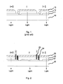
Fig. 1 shows a bottom emitting organic light emitting device comprising of series connected OLEDs according to the prior art.Fig.1 shows a layered structure over atransparent substrate 10, comprising a transparent bottom electrode 11, at least oneorganic semiconducting layer 12, and a reflectivetop electrode 13. The at least oneorganic semiconducting layer 12 and thetop electrode 13 need to be directly patterned by e.g. shadow masks or ink-jet printing. -
Fig. 2 shows a bottom emitting device comprising a pre-patternedbottom electrode 21 and an electrically insulatingseparator 25 over asubstrate 20. Organic layer(s) 22 and atop electrode 23 are produced without shadow masks. The separation of the individual OLEDs is provided by theelectrically insulating separators 25 during deposition of the layers. An interelectrode series connection 24 which may also referred to as an electrical top-electrode-bottom-electrode connection is made by a laser process. -
Fig. 3 shows a top emitting device with a layered structure comprising abottom electrode 31 over asubstrate 30, at least oneorganic semiconducting layer 32 between thebottom electrode 31 and atop electrode 33, wherein thetop electrode 33 is transparent and thesubstrate 30 and / or thebottom electrode 31 are reflective. The separation of the individual OLEDs is provided by electrically insulatingseparators 35 during deposition of the layers. An interelectrode series connection 34 is made by laser. -
Fig. 4 shows a transparent device with at least oneorganic semiconducting layer 42 in betweenelectrodes top electrode 43, thebottom electrode 41, and asubstrate 40 are transparent. An insulatingseparator 45 and the interelectrode series connection 44 provide the series connection of individual OLEDs (i+1, i, i-1, ...). -
Fig. 5 shows an array of series (column ..., i-1, i, i+1) connected OLEDs, which columns are connected in parallel (rows).Fig. 5 shows patternedbottom electrodes 51, an insulatingseparator 52, and an interelectrode series connection 54. The black lines (54) show where the laser is applied, obviously the inter electrode connection is formed only where top and bottom electrodes are provided. The columns can be connected in parallel by conductinglayers layer 53 which also provides the top electrode is only showed partially (for clarity reasons). - The
layer 56 is provided on top and in electrical contact to the bottom electrodes before the deposition of the organic layers. Alternatively or optionally, anoptional interconnection 57 can be used to provided the inter connection betweenconductive layer 56 and bottom electrodes. Other variations can be made, for example theconductive layer 56 does not overlap with the bottom electrodes, and the top conductive layer which also forms the top electrodes, plus the required interconnection, provides the necessary electrical path. Equivalent thinking can be applied to theconductive layer 55 and to other embodiments. Theconductive layer 55 can, optionally, be an extension of the top electrode layer, and be provided over the organic layer (this also applies to the other embodiments). -
Fig. 6 shows an array of series (column ..., i-1, i, i+1) connected OLEDs, which columns are connected in parallel (rows).Fig. 6 shows patternedbottom electrodes 61, an insulatingseparator 62, and an interelectrode series connection 64. The columns can be connected in parallel by conductinglayers layer 63 which also provides the top electrode is only showed partially (for clarity reasons). In this embodiment the insulatingseparator 62 is patterned in theareas bottom electrodes 61 can be patterned to be continuous between adjacent columns. Thebottom electrodes 61 of a row can optionally be a single layer (e.g. a strip). -
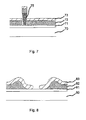
Fig. 7 shows a layered structure comprising asubstrate 70, a bottom electrode 71, at least oneorganic layer 72, and atop electrode 73. An insulatingseparator 75 is used to separate the at least oneorganic layer 72 and thetop electrode 73 into two regions. The insulatingseparator 75 has preferentially a cone (mushroom) format. This can be realized by constructing the insulatingseparator 75 from two photoresist with different etching speed (the lower part must have higher etching speed). -
Fig. 8 shows a mode for the inter electrode connection.Fig. 8 shows a layered structure comprising asubstrate 80, abottom electrode 81, at least oneorganic layer 82, and atop electrode 83. After fabricating the inter electrode connection by laser method as described above, the top electrode is in direct contact to the bottom electrode. The layer forming the top electrode does not necessarily need to be interrupted as shown inFig. 8 . - Following further embodiments are described by reference to device examples.
- The following terms are used: Spiro-TTB - octap-tolyl-9,9'-spirobi[fluorene]-2,2',7,7'-tetraamine-2,2',7,7'-tetrakis(N,N-di-p-methylphenylamino)-9,9'-spirobifluorene, F4TCNQ - 2,3,5,6-Tetrafluor-7,7,8,8-tetracyanochinodimethan, Spiro-TAD - 2,2',7,7'-Tetrakis(N,N-diphenylamino)-9,9'-spirobifluorene, Ir(ppy)3 - tris(2-phenylpyridine) iridium, TPBI - 1,3,5-Tris(1-phenyl-1H-benzimidazol-2-yl)benzene und BPhen - 2,9-Bis(naphthalen-2-yl)-4,7-diphenyl-1,10-phenanthroline.
- A 0,8 mm thick glass substrate, with lateral dimensions of 100 mm x 100 mm, was provided as substrate. The glass substrate contains a pre-pattemed ITO layer, patterned into 8 strips with lateral dimensions of 80 mm x 9,5 mm, spaced apart by 500 µm, except for the first strip which has an elongation to the edge (A) of the substrate which is used to supply electrical power to the device.
- A 2,3 µm thick photo definable polyimide layer (HD-8820 from HD microsystems) was deposited on the substrate by spin coating. The polyimide layer is heated at 120 °C for 3 minutes; the insulating separator is defined by exposing the polyimide layer to a light pattern for 50 seconds, developing for 120 seconds and heating at 180 °C for half an hour. The insulating separators are provided at 300 µm away from one edge of each patterned ITO strip. The area of 300 µm, between the insulating separator and the edge, is used for the top-electrode-bottom-electrode connection. The insulating separators are provided as 7 lines with a length of 82 mm.
- The stack of organic semiconducting layers was deposited by vacuum evaporation, over an area of 82 mm x 82 mm completely covering the ITO strips, except for the first strip which has an elongation to the edge of the substrate which is used to supply electrical power to the device. The stack of organic layers was made with the following layers:
- a hole transporting layer: 78 nm of Spiro-TTB, p-doped with 2mol% of F4TCNQ,
- an electron transport layer: 10 nm of Spiro-TAD,
- an
emitter layer 1, 5 nm of Spiro-TAD doped with 5mol% of Ir(ppy)3, - an
emitter layer 2, 10 nm of TPBI doped with 9mol% of Ir(ppy)3, - an electron transport layer, 10 nm of BPhen, and
- an electron transport layer, 30 nm of BPhen doped with Cs (molar ratio 1:1).
- A top electrode of 100 nm Al was deposited over an area of 80 mm x 90 mm, overlapping the ITO strips and extending to the edge of the substrate, which edge is opposite to the edge (A), providing an external electrical supply layer.
- The top electrode was interrupted by the insulating separators on the desired positions, electrically isolating the individual devices.
- The device was encapsulated using a rigid glass encapsulation cover glued to the glass substrate; the encapsulation also comprised an oxygen and moisture getter.
- The electrical top-electrode-bottom-electrode connection was formed by applying laser pulses on the edge of the ITO stripes forming 7 rows, between the insulating separator and the edge of the ITO stripes, forming the electrical connection in series. The laser used in this example was a pulsed Nd:YAG laser operating at 1064 nm. The laser process was done in air, because the device was encapsulated. It could also been done in inert atmosphere, before the encapsulation, which would, however increase process complexity.
- The laser pulses where applied trough the encapsulation, however, it could also be applied trough the substrate.
- The organic light emitting device worked as expected, having eight single light emitting diodes connected in series.
- The example above was repeated, with the insulating separator provided at a distance of 100 µm of the edge of the ITO strip. The inter electrode connection was formed on these 100 µm wide and 80 mm long area. With this method, not only the process is strongly simplified, but the connection area can be minimized. Even gaps between the ITO strips, as small as 100 µm can be used, decreasing the total dead area (area used for the connection, which do not emit light) to less than 300 µm.
- The features disclosed in this specification, claims and / or the figures may be material for the realization of the invention in its various embodiments, taken in isolation or in various combinations thereof.
Claims (12)
- A method for producing an organic light emitting device, especially a large area organic light emitting device, the method comprising steps of:- providing a plurality of organic light emitting diodes on a substrate, wherein the step of providing the plurality of organic light emitting diodes comprises steps of:- providing a bottom electrode for each of the plurality of organic light emitting diodes by depositing a patterned bottom conductive layer on the substrate;- providing a separator on the bottom conductive layer,- providing an organic layer for each of the plurality of organic light emitting diodes on the bottom conductive layer, and- providing a top electrode for each of the plurality of organic light emitting diodes by depositing a top conductive layer on the organic layer, top electrodes of adjacent organic light emitting diodes being separated by the separator,and- providing a series connection of the plurality of organic light emitting diodes, wherein the step of providing the series connection comprises steps of:- generating inter electrode series connections in a connection area,- providing each of the inter electrode series connections by electrically connecting a top electrode and a bottom electrode of adjacent organic light emitting diodes of the plurality of organic light emitting diodes, and- generating the inter electrode series connections by laser processing.
- Method according to claim 1, wherein the step of generating the inter electrode series connections by laser processing comprises a step irradiating laser light through the substrate.
- Method according to claim 1 or 2, the method further comprising a step of providing an encapsulation on the top electrode.
- Method according to claim 3, wherein the step of providing the series connection of the plurality of organic light emitting diodes is performed after the step of providing the encapsulation.
- Method according to at least one of the preceding claims, wherein the plurality of organic light emitting diodes is generated on the substrate by a maskless deposition process comprising a step of maskless depositing materials in at least an active area.
- Method according to at least one of the preceding claims, wherein the bottom electrode is provided as a transparent bottom electrode.
- Method according to at least one of the preceding claims, wherein the top electrode is provided as a transparent top electrode.
- Method according to at least one of the preceding claims, wherein the separator is provided as a tapered separator.
- Method according to at least one of the preceding claims, wherein the separator is provided with a plurality of sub-separators.
- Method according to at least one of the preceding claims, wherein the inter electrode series connection is provided adjacent to an electrode edge of the bottom electrode, and wherein the separator is provided adjacent to the inter electrode series connection on a side of the inter electrode series connection facing away from the electrode edge.
- Method according to at least one of the preceding claims, wherein the organic layer is provided with a redox doped layer adjacent to the top-electrode.
- An organic light emitting device, especially a large area organic light emitting device, made by a method according to a least one of the preceding claims, the device comprising:- a plurality of organic light emitting diodes on a substrate, each of the organic light emitting diodes comprising a bottom electrode, a top electrode and an organic layer located between the bottom electrode and the top electrode- an electrical separator electrically separating top electrodes of adjacent organic light emitting diodes of the plurality of organic light emitting diodes, and- inter electrode series connections electrically connecting a top electrode and a bottom electrode of adjacent organic light emitting diodes of the plurality of organic light emitting diodes, the inter electrode series connections providing a series connection of the plurality of organic light emitting diodes and being a laser generated connection.
Priority Applications (4)
| Application Number | Priority Date | Filing Date | Title |
|---|---|---|---|
| EP10000927.3A EP2355199B1 (en) | 2010-01-29 | 2010-01-29 | A method for producing an organic light emitting device |
| CN201010579211.7A CN102136549B (en) | 2009-12-03 | 2010-12-03 | For formed in organic optoelectronic device electrical interconnection method, for the manufacture of the method for organic optoelectronic device and organic luminescent device |
| KR1020100122581A KR101742114B1 (en) | 2009-12-03 | 2010-12-03 | A method for forming an electrical interconnection in an organic opto-electronic device, a method for producing an organic opto-electronic device, and an organic light emitting device |
| JP2010270603A JP2011124231A (en) | 2009-12-03 | 2010-12-03 | Method of forming electrical interconnect in organic optical electronic device, method of manufacturing organic optical electronic device, and organic light-emitting device |
Applications Claiming Priority (1)
| Application Number | Priority Date | Filing Date | Title |
|---|---|---|---|
| EP10000927.3A EP2355199B1 (en) | 2010-01-29 | 2010-01-29 | A method for producing an organic light emitting device |
Publications (2)
| Publication Number | Publication Date |
|---|---|
| EP2355199A1 true EP2355199A1 (en) | 2011-08-10 |
| EP2355199B1 EP2355199B1 (en) | 2017-07-05 |
Family
ID=42244511
Family Applications (1)
| Application Number | Title | Priority Date | Filing Date |
|---|---|---|---|
| EP10000927.3A Not-in-force EP2355199B1 (en) | 2009-12-03 | 2010-01-29 | A method for producing an organic light emitting device |
Country Status (1)
| Country | Link |
|---|---|
| EP (1) | EP2355199B1 (en) |
Cited By (10)
| Publication number | Priority date | Publication date | Assignee | Title |
|---|---|---|---|---|
| CN103262242A (en) * | 2010-12-03 | 2013-08-21 | 诺瓦莱德公开股份有限公司 | Method for forming an electrical interconnection in an organic photovoltaic device and an organic photovoltaic device made by the same |
| DE102012219712A1 (en) * | 2012-10-29 | 2014-04-30 | Tridonic Dresden Gmbh & Co. Kg | Light module with optimized contacting |
| DE102012021691A1 (en) | 2012-11-01 | 2014-05-08 | Fraunhofer-Gesellschaft zur Förderung der angewandten Forschung e.V. | Method for manufacturing organic LEDs or organic photovoltaic elements, involves removing material of organic multilayer structure in radiated region so that electrically conductive connection to substrate or layer is produced as electrode |
| US9209426B2 (en) | 2013-08-09 | 2015-12-08 | Semiconductor Energy Laboratory Co., Ltd. | Light-emitting element, display module, lighting module, light-emitting device, display device, electronic device, and lighting device |
| US9373809B2 (en) | 2011-05-27 | 2016-06-21 | Semiconductor Energy Laboratory Co., Ltd. | Electroluminescent device and method of manufacturing thereof |
| US9515278B2 (en) | 2013-08-09 | 2016-12-06 | Semiconductor Energy Laboratory Co., Ltd. | Light-emitting element, display module, lighting module, light-emitting device, display device, electronic device, and lighting device |
| WO2018134340A1 (en) * | 2017-01-20 | 2018-07-26 | Opvius Gmbh | Method for producing an organic semiconductor component, and organic semiconductor component |
| DE102017101390A1 (en) | 2017-01-25 | 2018-07-26 | Osram Oled Gmbh | Organic light emitting device and method of making an organic light emitting device |
| US10153449B2 (en) | 2014-10-16 | 2018-12-11 | Semiconductor Energy Laboratory Co., Ltd. | Light-emitting element, light-emitting device, electronic device, and lighting device |
| US10777693B2 (en) | 2013-12-17 | 2020-09-15 | Oxford University Innovation Limited | Photovoltaic device comprising a metal halide perovskite and a passivating agent |
Citations (6)
| Publication number | Priority date | Publication date | Assignee | Title |
|---|---|---|---|---|
| EP0949696A2 (en) * | 1998-04-08 | 1999-10-13 | Idemitsu Kosan Company Limited | Organic electroluminescent device |
| EP1388894A2 (en) * | 2002-08-07 | 2004-02-11 | Eastman Kodak Company | OLED apparatus including a series of OLED devices |
| US7049757B2 (en) | 2002-08-05 | 2006-05-23 | General Electric Company | Series connected OLED structure and fabrication method |
| US20060152833A1 (en) * | 2002-12-20 | 2006-07-13 | Cambridge Display Technology Limited | Electrical connection of optoelectronic devices |
| US20070295400A1 (en) * | 2004-05-14 | 2007-12-27 | Konarka Technologies Gmbh | Roll to roll manufacturing of organic solar modules |
| US20100019660A1 (en) * | 2008-07-23 | 2010-01-28 | Sung-Soo Lee | Organic light emitting display and method of manufacturing the same |
Family Cites Families (1)
| Publication number | Priority date | Publication date | Assignee | Title |
|---|---|---|---|---|
| JP4356899B2 (en) * | 2007-03-15 | 2009-11-04 | 財団法人山形県産業技術振興機構 | Organic EL light emitting device and method for manufacturing the same |
-
2010
- 2010-01-29 EP EP10000927.3A patent/EP2355199B1/en not_active Not-in-force
Patent Citations (6)
| Publication number | Priority date | Publication date | Assignee | Title |
|---|---|---|---|---|
| EP0949696A2 (en) * | 1998-04-08 | 1999-10-13 | Idemitsu Kosan Company Limited | Organic electroluminescent device |
| US7049757B2 (en) | 2002-08-05 | 2006-05-23 | General Electric Company | Series connected OLED structure and fabrication method |
| EP1388894A2 (en) * | 2002-08-07 | 2004-02-11 | Eastman Kodak Company | OLED apparatus including a series of OLED devices |
| US20060152833A1 (en) * | 2002-12-20 | 2006-07-13 | Cambridge Display Technology Limited | Electrical connection of optoelectronic devices |
| US20070295400A1 (en) * | 2004-05-14 | 2007-12-27 | Konarka Technologies Gmbh | Roll to roll manufacturing of organic solar modules |
| US20100019660A1 (en) * | 2008-07-23 | 2010-01-28 | Sung-Soo Lee | Organic light emitting display and method of manufacturing the same |
Cited By (18)
| Publication number | Priority date | Publication date | Assignee | Title |
|---|---|---|---|---|
| CN103262242A (en) * | 2010-12-03 | 2013-08-21 | 诺瓦莱德公开股份有限公司 | Method for forming an electrical interconnection in an organic photovoltaic device and an organic photovoltaic device made by the same |
| US9373809B2 (en) | 2011-05-27 | 2016-06-21 | Semiconductor Energy Laboratory Co., Ltd. | Electroluminescent device and method of manufacturing thereof |
| DE102012219712A1 (en) * | 2012-10-29 | 2014-04-30 | Tridonic Dresden Gmbh & Co. Kg | Light module with optimized contacting |
| US9349973B2 (en) | 2012-10-29 | 2016-05-24 | Tridonic Gmbh & Co. Kg | Lighting module with optimized contacting |
| DE102012021691A1 (en) | 2012-11-01 | 2014-05-08 | Fraunhofer-Gesellschaft zur Förderung der angewandten Forschung e.V. | Method for manufacturing organic LEDs or organic photovoltaic elements, involves removing material of organic multilayer structure in radiated region so that electrically conductive connection to substrate or layer is produced as electrode |
| US9780338B2 (en) | 2013-08-09 | 2017-10-03 | Semiconductor Energy Laboratory Co., Ltd. | Light-emitting element, display module, lighting module, light-emitting device, display device, electronic device, and lighting device |
| US9401483B2 (en) | 2013-08-09 | 2016-07-26 | Semiconductor Energy Laboratory Co., Ltd. | Light-emitting element, display module, lighting module, light-emitting device, display device, electronic device, and lighting device |
| US9515278B2 (en) | 2013-08-09 | 2016-12-06 | Semiconductor Energy Laboratory Co., Ltd. | Light-emitting element, display module, lighting module, light-emitting device, display device, electronic device, and lighting device |
| US9209426B2 (en) | 2013-08-09 | 2015-12-08 | Semiconductor Energy Laboratory Co., Ltd. | Light-emitting element, display module, lighting module, light-emitting device, display device, electronic device, and lighting device |
| US9966574B2 (en) | 2013-08-09 | 2018-05-08 | Semiconductor Energy Laboratory Co., Ltd. | Light-emitting element, display module, lighting module, light-emitting device, display device, electronic device, and lighting device |
| US10777693B2 (en) | 2013-12-17 | 2020-09-15 | Oxford University Innovation Limited | Photovoltaic device comprising a metal halide perovskite and a passivating agent |
| US11799039B2 (en) | 2013-12-17 | 2023-10-24 | Oxford University Innovation Limited | Photovoltaic device comprising a metal halide perovskite and a passivating agent |
| US12288825B2 (en) | 2013-12-17 | 2025-04-29 | Oxford Photovoltaics Limited | Photovoltaic device comprising a metal halide perovskite and a passivating agent |
| US10153449B2 (en) | 2014-10-16 | 2018-12-11 | Semiconductor Energy Laboratory Co., Ltd. | Light-emitting element, light-emitting device, electronic device, and lighting device |
| WO2018134340A1 (en) * | 2017-01-20 | 2018-07-26 | Opvius Gmbh | Method for producing an organic semiconductor component, and organic semiconductor component |
| DE102017200896A1 (en) * | 2017-01-20 | 2018-07-26 | Opvius Gmbh | Process for producing an organic semiconductor device and organic semiconductor device |
| DE102017101390A1 (en) | 2017-01-25 | 2018-07-26 | Osram Oled Gmbh | Organic light emitting device and method of making an organic light emitting device |
| DE102017101390B4 (en) | 2017-01-25 | 2026-07-09 | Pictiva Displays International Limited | Organic light-emitting device and method for manufacturing an organic light-emitting device |
Also Published As
| Publication number | Publication date |
|---|---|
| EP2355199B1 (en) | 2017-07-05 |
Similar Documents
| Publication | Publication Date | Title |
|---|---|---|
| EP2355199B1 (en) | A method for producing an organic light emitting device | |
| EP1930967B1 (en) | Method of making an organic light emitting display apparatus and apparatus therefor | |
| CN102549797B (en) | Monolithic parallel interconnect structure | |
| KR100890250B1 (en) | Method of manufacturing a flexible device and method of manufacturing a flexible display | |
| CN102144314B (en) | Method for producing an organic radiation-emitting component and organic radiation-emitting component | |
| KR100685804B1 (en) | Organic Electroluminescence Device and Fabricating Method of the same | |
| US20060125390A1 (en) | Organic light emitting display with auxiliary electrode line and method of fabricating the same | |
| KR101742114B1 (en) | A method for forming an electrical interconnection in an organic opto-electronic device, a method for producing an organic opto-electronic device, and an organic light emitting device | |
| CN102696125A (en) | Method of maskless manufacturing of OLED devices | |
| EP2333859B1 (en) | A method for forming an organic light emitting diode | |
| JP7773806B2 (en) | solar cell element | |
| CN102812577B (en) | The method manufacturing the OLED of the luminous zone with space isolation | |
| CN102652371B (en) | For creating the method for the OLED be connected in series | |
| JP6143763B2 (en) | Improved masking for light emitting device patterns | |
| JP2022151107A (en) | element | |
| KR20140019549A (en) | A manufacturing method of an orgarnic light emitting device | |
| WO2017144308A1 (en) | Organic light-emitting component and method for producing an organic light-emitting component | |
| KR20110103050A (en) | Method for manufacturing organic light emitting device | |
| KR20070037851A (en) | Display device and manufacturing method thereof |
Legal Events
| Date | Code | Title | Description |
|---|---|---|---|
| PUAI | Public reference made under article 153(3) epc to a published international application that has entered the european phase |
Free format text: ORIGINAL CODE: 0009012 |
|
| AK | Designated contracting states |
Kind code of ref document: A1 Designated state(s): AT BE BG CH CY CZ DE DK EE ES FI FR GB GR HR HU IE IS IT LI LT LU LV MC MK MT NL NO PL PT RO SE SI SK SM TR |
|
| AX | Request for extension of the european patent |
Extension state: AL BA RS |
|
| 17P | Request for examination filed |
Effective date: 20120210 |
|
| 17Q | First examination report despatched |
Effective date: 20120510 |
|
| GRAP | Despatch of communication of intention to grant a patent |
Free format text: ORIGINAL CODE: EPIDOSNIGR1 |
|
| INTG | Intention to grant announced |
Effective date: 20170130 |
|
| GRAS | Grant fee paid |
Free format text: ORIGINAL CODE: EPIDOSNIGR3 |
|
| GRAA | (expected) grant |
Free format text: ORIGINAL CODE: 0009210 |
|
| RIN1 | Information on inventor provided before grant (corrected) |
Inventor name: LESSMANN, RUDOLF Inventor name: BLOCHWITZ-NIMOTH, JAN Inventor name: WERNER, ANSGAR |
|
| RAP1 | Party data changed (applicant data changed or rights of an application transferred) |
Owner name: NOVALED GMBH |
|
| AK | Designated contracting states |
Kind code of ref document: B1 Designated state(s): AT BE BG CH CY CZ DE DK EE ES FI FR GB GR HR HU IE IS IT LI LT LU LV MC MK MT NL NO PL PT RO SE SI SK SM TR |
|
| REG | Reference to a national code |
Ref country code: GB Ref legal event code: FG4D |
|
| REG | Reference to a national code |
Ref country code: CH Ref legal event code: EP |
|
| REG | Reference to a national code |
Ref country code: AT Ref legal event code: REF Ref document number: 907152 Country of ref document: AT Kind code of ref document: T Effective date: 20170715 |
|
| REG | Reference to a national code |
Ref country code: IE Ref legal event code: FG4D |
|
| REG | Reference to a national code |
Ref country code: DE Ref legal event code: R096 Ref document number: 602010043381 Country of ref document: DE |
|
| REG | Reference to a national code |
Ref country code: NL Ref legal event code: MP Effective date: 20170705 |
|
| REG | Reference to a national code |
Ref country code: AT Ref legal event code: MK05 Ref document number: 907152 Country of ref document: AT Kind code of ref document: T Effective date: 20170705 |
|
| REG | Reference to a national code |
Ref country code: LT Ref legal event code: MG4D |
|
| REG | Reference to a national code |
Ref country code: FR Ref legal event code: PLFP Year of fee payment: 9 |
|
| PG25 | Lapsed in a contracting state [announced via postgrant information from national office to epo] |
Ref country code: NO Free format text: LAPSE BECAUSE OF FAILURE TO SUBMIT A TRANSLATION OF THE DESCRIPTION OR TO PAY THE FEE WITHIN THE PRESCRIBED TIME-LIMIT Effective date: 20171005 Ref country code: SE Free format text: LAPSE BECAUSE OF FAILURE TO SUBMIT A TRANSLATION OF THE DESCRIPTION OR TO PAY THE FEE WITHIN THE PRESCRIBED TIME-LIMIT Effective date: 20170705 Ref country code: HR Free format text: LAPSE BECAUSE OF FAILURE TO SUBMIT A TRANSLATION OF THE DESCRIPTION OR TO PAY THE FEE WITHIN THE PRESCRIBED TIME-LIMIT Effective date: 20170705 Ref country code: AT Free format text: LAPSE BECAUSE OF FAILURE TO SUBMIT A TRANSLATION OF THE DESCRIPTION OR TO PAY THE FEE WITHIN THE PRESCRIBED TIME-LIMIT Effective date: 20170705 Ref country code: LT Free format text: LAPSE BECAUSE OF FAILURE TO SUBMIT A TRANSLATION OF THE DESCRIPTION OR TO PAY THE FEE WITHIN THE PRESCRIBED TIME-LIMIT Effective date: 20170705 Ref country code: NL Free format text: LAPSE BECAUSE OF FAILURE TO SUBMIT A TRANSLATION OF THE DESCRIPTION OR TO PAY THE FEE WITHIN THE PRESCRIBED TIME-LIMIT Effective date: 20170705 Ref country code: FI Free format text: LAPSE BECAUSE OF FAILURE TO SUBMIT A TRANSLATION OF THE DESCRIPTION OR TO PAY THE FEE WITHIN THE PRESCRIBED TIME-LIMIT Effective date: 20170705 |
|
| PG25 | Lapsed in a contracting state [announced via postgrant information from national office to epo] |
Ref country code: LV Free format text: LAPSE BECAUSE OF FAILURE TO SUBMIT A TRANSLATION OF THE DESCRIPTION OR TO PAY THE FEE WITHIN THE PRESCRIBED TIME-LIMIT Effective date: 20170705 Ref country code: IS Free format text: LAPSE BECAUSE OF FAILURE TO SUBMIT A TRANSLATION OF THE DESCRIPTION OR TO PAY THE FEE WITHIN THE PRESCRIBED TIME-LIMIT Effective date: 20171105 Ref country code: ES Free format text: LAPSE BECAUSE OF FAILURE TO SUBMIT A TRANSLATION OF THE DESCRIPTION OR TO PAY THE FEE WITHIN THE PRESCRIBED TIME-LIMIT Effective date: 20170705 Ref country code: BG Free format text: LAPSE BECAUSE OF FAILURE TO SUBMIT A TRANSLATION OF THE DESCRIPTION OR TO PAY THE FEE WITHIN THE PRESCRIBED TIME-LIMIT Effective date: 20171005 Ref country code: GR Free format text: LAPSE BECAUSE OF FAILURE TO SUBMIT A TRANSLATION OF THE DESCRIPTION OR TO PAY THE FEE WITHIN THE PRESCRIBED TIME-LIMIT Effective date: 20171006 Ref country code: PL Free format text: LAPSE BECAUSE OF FAILURE TO SUBMIT A TRANSLATION OF THE DESCRIPTION OR TO PAY THE FEE WITHIN THE PRESCRIBED TIME-LIMIT Effective date: 20170705 |
|
| REG | Reference to a national code |
Ref country code: DE Ref legal event code: R097 Ref document number: 602010043381 Country of ref document: DE |
|
| PG25 | Lapsed in a contracting state [announced via postgrant information from national office to epo] |
Ref country code: RO Free format text: LAPSE BECAUSE OF FAILURE TO SUBMIT A TRANSLATION OF THE DESCRIPTION OR TO PAY THE FEE WITHIN THE PRESCRIBED TIME-LIMIT Effective date: 20170705 Ref country code: CZ Free format text: LAPSE BECAUSE OF FAILURE TO SUBMIT A TRANSLATION OF THE DESCRIPTION OR TO PAY THE FEE WITHIN THE PRESCRIBED TIME-LIMIT Effective date: 20170705 Ref country code: DK Free format text: LAPSE BECAUSE OF FAILURE TO SUBMIT A TRANSLATION OF THE DESCRIPTION OR TO PAY THE FEE WITHIN THE PRESCRIBED TIME-LIMIT Effective date: 20170705 |
|
| PLBE | No opposition filed within time limit |
Free format text: ORIGINAL CODE: 0009261 |
|
| STAA | Information on the status of an ep patent application or granted ep patent |
Free format text: STATUS: NO OPPOSITION FILED WITHIN TIME LIMIT |
|
| PG25 | Lapsed in a contracting state [announced via postgrant information from national office to epo] |
Ref country code: IT Free format text: LAPSE BECAUSE OF FAILURE TO SUBMIT A TRANSLATION OF THE DESCRIPTION OR TO PAY THE FEE WITHIN THE PRESCRIBED TIME-LIMIT Effective date: 20170705 Ref country code: EE Free format text: LAPSE BECAUSE OF FAILURE TO SUBMIT A TRANSLATION OF THE DESCRIPTION OR TO PAY THE FEE WITHIN THE PRESCRIBED TIME-LIMIT Effective date: 20170705 Ref country code: SM Free format text: LAPSE BECAUSE OF FAILURE TO SUBMIT A TRANSLATION OF THE DESCRIPTION OR TO PAY THE FEE WITHIN THE PRESCRIBED TIME-LIMIT Effective date: 20170705 Ref country code: SK Free format text: LAPSE BECAUSE OF FAILURE TO SUBMIT A TRANSLATION OF THE DESCRIPTION OR TO PAY THE FEE WITHIN THE PRESCRIBED TIME-LIMIT Effective date: 20170705 |
|
| 26N | No opposition filed |
Effective date: 20180406 |
|
| PG25 | Lapsed in a contracting state [announced via postgrant information from national office to epo] |
Ref country code: SI Free format text: LAPSE BECAUSE OF FAILURE TO SUBMIT A TRANSLATION OF THE DESCRIPTION OR TO PAY THE FEE WITHIN THE PRESCRIBED TIME-LIMIT Effective date: 20170705 |
|
| REG | Reference to a national code |
Ref country code: CH Ref legal event code: PL |
|
| PG25 | Lapsed in a contracting state [announced via postgrant information from national office to epo] |
Ref country code: LU Free format text: LAPSE BECAUSE OF NON-PAYMENT OF DUE FEES Effective date: 20180129 |
|
| REG | Reference to a national code |
Ref country code: IE Ref legal event code: MM4A |
|
| REG | Reference to a national code |
Ref country code: BE Ref legal event code: MM Effective date: 20180131 |
|
| PG25 | Lapsed in a contracting state [announced via postgrant information from national office to epo] |
Ref country code: LI Free format text: LAPSE BECAUSE OF NON-PAYMENT OF DUE FEES Effective date: 20180131 Ref country code: BE Free format text: LAPSE BECAUSE OF NON-PAYMENT OF DUE FEES Effective date: 20180131 Ref country code: CH Free format text: LAPSE BECAUSE OF NON-PAYMENT OF DUE FEES Effective date: 20180131 |
|
| PG25 | Lapsed in a contracting state [announced via postgrant information from national office to epo] |
Ref country code: IE Free format text: LAPSE BECAUSE OF NON-PAYMENT OF DUE FEES Effective date: 20180129 |
|
| PG25 | Lapsed in a contracting state [announced via postgrant information from national office to epo] |
Ref country code: MC Free format text: LAPSE BECAUSE OF FAILURE TO SUBMIT A TRANSLATION OF THE DESCRIPTION OR TO PAY THE FEE WITHIN THE PRESCRIBED TIME-LIMIT Effective date: 20170705 |
|
| PG25 | Lapsed in a contracting state [announced via postgrant information from national office to epo] |
Ref country code: MT Free format text: LAPSE BECAUSE OF NON-PAYMENT OF DUE FEES Effective date: 20180129 |
|
| PG25 | Lapsed in a contracting state [announced via postgrant information from national office to epo] |
Ref country code: TR Free format text: LAPSE BECAUSE OF FAILURE TO SUBMIT A TRANSLATION OF THE DESCRIPTION OR TO PAY THE FEE WITHIN THE PRESCRIBED TIME-LIMIT Effective date: 20170705 |
|
| PG25 | Lapsed in a contracting state [announced via postgrant information from national office to epo] |
Ref country code: PT Free format text: LAPSE BECAUSE OF FAILURE TO SUBMIT A TRANSLATION OF THE DESCRIPTION OR TO PAY THE FEE WITHIN THE PRESCRIBED TIME-LIMIT Effective date: 20170705 Ref country code: HU Free format text: LAPSE BECAUSE OF FAILURE TO SUBMIT A TRANSLATION OF THE DESCRIPTION OR TO PAY THE FEE WITHIN THE PRESCRIBED TIME-LIMIT; INVALID AB INITIO Effective date: 20100129 |
|
| PG25 | Lapsed in a contracting state [announced via postgrant information from national office to epo] |
Ref country code: MK Free format text: LAPSE BECAUSE OF NON-PAYMENT OF DUE FEES Effective date: 20170705 Ref country code: CY Free format text: LAPSE BECAUSE OF FAILURE TO SUBMIT A TRANSLATION OF THE DESCRIPTION OR TO PAY THE FEE WITHIN THE PRESCRIBED TIME-LIMIT Effective date: 20170705 |
|
| REG | Reference to a national code |
Ref country code: DE Ref legal event code: R079 Ref document number: 602010043381 Country of ref document: DE Free format text: PREVIOUS MAIN CLASS: H01L0051520000 Ipc: H10K0050800000 |
|
| P01 | Opt-out of the competence of the unified patent court (upc) registered |
Effective date: 20230515 |
|
| PGFP | Annual fee paid to national office [announced via postgrant information from national office to epo] |
Ref country code: GB Payment date: 20231207 Year of fee payment: 15 |
|
| PGFP | Annual fee paid to national office [announced via postgrant information from national office to epo] |
Ref country code: FR Payment date: 20231212 Year of fee payment: 15 |
|
| PGFP | Annual fee paid to national office [announced via postgrant information from national office to epo] |
Ref country code: DE Payment date: 20231205 Year of fee payment: 15 |
|
| REG | Reference to a national code |
Ref country code: DE Ref legal event code: R119 Ref document number: 602010043381 Country of ref document: DE |
|
| GBPC | Gb: european patent ceased through non-payment of renewal fee |
Effective date: 20250129 |
|
| PG25 | Lapsed in a contracting state [announced via postgrant information from national office to epo] |
Ref country code: DE Free format text: LAPSE BECAUSE OF NON-PAYMENT OF DUE FEES Effective date: 20250801 |
|
| PG25 | Lapsed in a contracting state [announced via postgrant information from national office to epo] |
Ref country code: GB Free format text: LAPSE BECAUSE OF NON-PAYMENT OF DUE FEES Effective date: 20250129 |
|
| PG25 | Lapsed in a contracting state [announced via postgrant information from national office to epo] |
Ref country code: FR Free format text: LAPSE BECAUSE OF NON-PAYMENT OF DUE FEES Effective date: 20250131 |