EP2354880A1 - Temperaturgesteuerter Ventileinsatz - Google Patents
Temperaturgesteuerter Ventileinsatz Download PDFInfo
- Publication number
- EP2354880A1 EP2354880A1 EP10152617A EP10152617A EP2354880A1 EP 2354880 A1 EP2354880 A1 EP 2354880A1 EP 10152617 A EP10152617 A EP 10152617A EP 10152617 A EP10152617 A EP 10152617A EP 2354880 A1 EP2354880 A1 EP 2354880A1
- Authority
- EP
- European Patent Office
- Prior art keywords
- hot water
- intake
- temperature controlled
- housing part
- bottom end
- Prior art date
- Legal status (The legal status is an assumption and is not a legal conclusion. Google has not performed a legal analysis and makes no representation as to the accuracy of the status listed.)
- Withdrawn
Links
Images


Classifications
-
- G—PHYSICS
- G05—CONTROLLING; REGULATING
- G05D—SYSTEMS FOR CONTROLLING OR REGULATING NON-ELECTRIC VARIABLES
- G05D23/00—Control of temperature
- G05D23/01—Control of temperature without auxiliary power
- G05D23/13—Control of temperature without auxiliary power by varying the mixing ratio of two fluids having different temperatures
- G05D23/1306—Control of temperature without auxiliary power by varying the mixing ratio of two fluids having different temperatures for liquids
- G05D23/132—Control of temperature without auxiliary power by varying the mixing ratio of two fluids having different temperatures for liquids with temperature sensing element
- G05D23/134—Control of temperature without auxiliary power by varying the mixing ratio of two fluids having different temperatures for liquids with temperature sensing element measuring the temperature of mixed fluid
- G05D23/1346—Control of temperature without auxiliary power by varying the mixing ratio of two fluids having different temperatures for liquids with temperature sensing element measuring the temperature of mixed fluid with manual temperature setting means
- G05D23/1353—Control of temperature without auxiliary power by varying the mixing ratio of two fluids having different temperatures for liquids with temperature sensing element measuring the temperature of mixed fluid with manual temperature setting means combined with flow controlling means
Definitions
- the present invention relates to a temperature controlled valve core that can utilize a single rotating component to open and close water supply, and to adjust temperature at a stable range.
- Conventional temperature controlled valve core is used to supply water at a stable temperature by changing temperature or/and pressure of cold and hot waters, accordingly a heat sensitive element is provided to adjust the temperature of mixed cold and hot water to keep the temperature at a stable status.
- a temperature adjustable valve core disclosed in Publication No. 20080035744 comprises temperature adjusting assembly including a flow amount adjusting component and a temperature adjusting component to control flowing amount and temperature individually.
- the flow amount adjusting component is used to rotably actuate a movable disc and a fixed disc relative to the movable disc to act so that a first tunnel to flow hot fluid, a second tunnel to flow cold fluid, and a third tunnel to flow mixed cold and hot water move at opposite positions to change communicating state with each other.
- the temperature adjusting component is applied an adjustable screw to axially actuate a heat sensitive element and an upper sliding valve to change flowing amount of the mixed cold and hot water in a chamber.
- the heat sensitive element includes a heat sensing portion disposed on a flowing path of the mixed cold and hot water to sense the temperature of the flowing water, such that a plunger on one end of the heat sensitive element expands and retracts to actuate the sliding valve to move axially so as to adjust flowing amount of the mixed cold and hot water in the chamber automatically, thus obtaining a stable temperature.
- the present invention has arisen to mitigate and/or obviate the afore-described disadvantages.
- the primary object of the present invention is to provide a temperature controlled valve core that can utilize a single rotating component to open and close water supply, and to adjust temperature at a stable range.
- Another object of the present invention is to provide a temperature controlled valve core that can if the cold water stops supply, the temperature of the mixed cold and hot water raises at instant, then the sensing portion of the plunger of the heat sensitive element senses the raised temperature of the mixed cold and hot water to expand the plunger quickly so that the inlet valve is pushed by the plunger adversely to move downward to close the second intake, obtaining anti-scald safety.
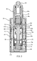
- a temperature controlled valve core according to a preferred embodiment of the present invention comprises a housing a, a seat b, and an adjusting assembly c; the housing a including a lower housing part 10, an upper housing part 20 sealed to a top end of the lower housing part 10, and a casing 30 sealed to the lower housing part 10 and a partial exterior of the upper housing part 20, the housing a also including a receiving space defined in a partial interior thereof, wherein the lower housing part 10 as shown in Figs.
- first tunnel 13 extends upward to a first height from a bottom end of the lower housing part 10, and communicates with the first room 11 through a first orifice 131 which passes through the first peripheral fence 12.
- the first tunnel 13 communicates with the first room 11 via two second orifices 132 which pass through the first peripheral fence 12, and between the first and the second orifices 131, 132 is defined a ditch 133 to communicate with the first and the second orifices 131, 132 so that cold water from a top end of the first tunnel 13 flows to the first and the second orifices 131, 132 and further flows into the first room 11 evenly.
- the second tunnel 14 extends upward from the bottom end of the lower housing part 10 to a second height, and then communicates with the first room 11 via a third orifice 141 which passes through the first peripheral fence 12.
- the second tunnel 14 extends upward from the bottom end of the lower housing part 10 to the second height via two fourth orifices 142 which pass through the first peripheral fence 12, and between the third and the fourth orifices 141, 142 is defined a trench 143 to communicate with the third and the fourth orifices 141, 142 so that hot water from a top end of the second tunnel 14 flows to the first room 11 evenly from the third and the fourth orifices 141, 142.
- the first height where the top end of the first tunnel 13 is located is higher than the second height where the top end of the second tunnel 14 is located, e.g., cold water flows inward from a higher position of the first room 11, and hot water flows inward from a lower position thereof.
- the channel 15 extends to the top end of the lower housing part 10 from the bottom end of the lower housing part 10 so that the mixed cold and hot water from a top end of the channel 15 flows downward.
- the lower housing part 10 includes first outer threads 16 formed on an outer surface of the top end thereof, and the first room 11 includes a fixing fringe 17 formed on an inner surface thereof where is located at top ends of the first and the second orifices 131, 132, and includes an enclosure tab 18 fixed on the inner surface thereof where is located at bottom ends of the third and the fourth orifices 141, 142, and includes a first positioning notch 19 disposed on a bottom end thereof.
- the lower housing part 10 includes two engaging members 121 symmetrically secured on a lower side thereof proximate to an outer side of the first peripheral fence 12.
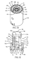
- the upper housing part 20 as illustrated in Fig. 8 is formed in a sleeve shape, and includes a larger-diameter screwing portion 21 mounted on a lower side thereof, and includes a smaller-diameter receiving segment 22 arranged on an upper side thereof, and includes a stepped abutting shoulder 23 formed on an exterior thereof, the screwing portion 21 includes inner threads 211 attached in an interior thereof to screw with the first outer threads 16 of the lower housing part 10.
- the receiving segment 22 includes a second room 221 formed therein, and the second room 221 includes a number of protrusions extending around an inner surface of an upper side thereof to define a defining trough 222 between each two protrusions, and includes a mouth 223 with a smaller diameter disposed on a top end thereof, the mouth 223 includes a first hole 224 mounted on a top surface thereof.
- An outer peripheral surface of the receiving segment 22 is polygonal to fit a specific tool and be rotated by the tool.
- the casing 30 as shown in Figs. 2 and 3 is formed in a cover shape, and includes an internal area 31 having a second opening 311, and includes a second hole 32 fixed on a top surface thereof to inert the receiving segment 22 of the upper housing part 20 upward so that the casing 30 fits to the screwing portion 21 of the upper housing part 20 and the lower housing part 10 and to close an outer peripheral surface of the lower housing part 20 so that the first and the second orifices 131, 132 of the first tunnel 13 of the lower housing part 20 and the third and the fourth orifices 141, 142 of the second tunnel 14 are closed to flow the cold water and the hot water toward the first room 11.
- the casing 30 further includes two retaining recesses 33 fixed at two symmetrical positions of a bottom end thereof respectively, and each recess 33 includes two slots 34 formed on two sides thereof so that the casing 30 covers to a part of the upper housing part 20 and the lower housing part 10, and a top surface of the internal area 31 engages with the abutting shoulder 23 of the screwing portion 21 of the upper housing part 20, the retaining recesses 33 engage with the engaging members 121, thus closing the lower and the upper housing parts 10, 20 tightly.
- the receiving space of the housing a is comprised of the first room 11 of the lower housing part 10, the second room 221 of the upper housing part 20, and the screwing portion 21 of the upper housing part 20.
- the seat b as shown in Figs. 9 , 10 is positioned to an upper side of the first room 11 of the lower housing part 10, and includes a first chamber 401 to receive mixed cold and hot water arranged therein to communicate with the channel 15 of the lower housing part 10.
- the seat b includes an outer periphery 40a and a locking loop 40b, wherein the outer periphery 40a is formed in a circular loop and fixed on the upper side of the first room 11 of the lower housing part 10, and a bottom end of a first peripheral side 41 thereof engages with the fixing fringe 17 of the lower housing part 10, the peripheral side 41 of the outer periphery 40a includes a first bottom rim 42 secured around the bottom end thereof, and the outer periphery 40a allows to define most part of the first chamber 401 by using an inner space thereof.
- the locking loop 40b includes a first top cliff 43 and a second peripheral side 44 extending downward, the second peripheral side 44 couples with the outer periphery 40a.
- a top surface of the first top cliff 43 flushes with the top end of the lower housing part 10, and includes a plurality of biasing members 45 secured thereon, and between each two biasing members 45 is defined a cutout 451, and a top end of the biasing member 45 is screwed with the screwing portion 21 of the upper housing part 20 to be abutted downward so that the seat b is positioned between the first room 11 of the lower housing part 10 and the screwing portion 21 of the upper housing part 20 securely.
- the first top cliff 43 includes a first bore 431 disposed on a central portion thereof, and between the first bore 431 and the top cutout 451 is defined a first closing portion 432.
- the first closing portion 432 is comprised of a stop pad retained in an annular indention of the top surface of the first top cliff 43.
- the locking loop 40b allows to define a small part of the first chamber 401 by using a space between a lower side of the first top cliff 43 and the second peripheral side 44, the first chamber 401 communicates with the channel 15 via the first bore 431 and the cutouts 451.
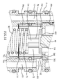
- the adjusting assembly c as illustrated in Figs. 11-13 is installed between the housing a and the seat b, and includes a rotating component 50, a watering valve 60, an inlet valve 70, a heat sensitive element 80, and an elastic returning element 90, wherein
- the rotating component 50 is formed in a shaft shape, and includes second outer threads 51 arranged on a bottom end thereof, and includes a sealing portion 52 fixed on a middle section thereof, and a rotary shaft 53 disposed on a top end thereof.
- the rotary shaft 53 extends out of the first hole 224 of the upper housing part 20 to be rotated.
- the sealing portion 52 is rotatably retained to the mouth 223 so that the rotating component 50 is driven to rotate on the top end of the upper housing part 20.
- the watering valve 60 is actuated by the rotating component 50 to move upward and downward.
- the watering valve 60 includes an actuating member 60a, a seal sleeve 60b, a resilient protecting element 60c, and a pushing element 60d.
- the actuating member 60a includes a first and a second screwing grooves 61, 62 mounted on a top and a bottom ends thereof individually, and the first screwing groove 61 screws with the second threads 51 of the adjusting component 50, the second screwing groove 62 includes a second positioning notch 621 defined on an upper side thereof.
- the seal slave 60b includes third threads 63 mounted on a top end thereof to screw with the second screwing groove 62 of the actuating member 60a, and includes a third positioning notch 64 arranged therein, and the third positioning notch 64 includes a second bore 65 fixed on a center of a bottom end thereof, the seal sleeve 60b includes a raised second closing portion 66 extending from a bottom surface thereof.
- the actuating member 60a includes a number of limiting blocks 67 extending around the top end thereof to engage with the defining troughs 222 of the second room 221 of the upper housing part 20 so that the actuating member 60a is limited to rotate, hence when the rotating component 50 is rotated, the actuating member 60a is actuated to move upward and downward.
- the resilient protecting element 60c is a compression spring to be installed in the cavity 601 of the watering valve 60, and a top end of the resilient protecting element 60a retains with the second positioning notch 621 of the actuating member 60a.
- the pushing element 60d is installed to the third positioning notch 64 of the watering valve 60, and a top end of the pushing element 60d abuts against a bottom end of the resilient protecting element 60c, a bottom end of the pushing element 60d engages with the third positioning notch 64 of the seal sleeve 60b, and the pushing element 60d includes an aperture 60 disposed on a center thereof.
- the watering valve 60 is actuated to move downward so that the second closing portion 66 of the seal sleeve 60b engages with the first closing portion 432 of the locking loop 40b of the seat b, and watering paths between the first bore 431 and the cutouts 451 are closed.
- the second closing portion 66 disengages from the first closing portion 432 to generate a watering outlet 602, as shown in Fig. 3 , the mixed cold and hot water from the first chamber 401 flows to the top end of the channel 15 through the first bore 431, the watering outlet 602, and the cutouts 451.
- the inlet valve 70 is received in a middle area of the first room 11 of the lower housing part 10 to move upward and downward so as to control flowing amount of the cold water and the hot water flowing from the top end of the first tunnel 13, and the top end of the second tunnel 14, and the first room 11 of the lower housing part 10.
- the inlet valve 70 includes a third closing portion 70a and a fitting portion 70b, wherein:
- the fitting portion 70b is received in the first chamber 401 of the seat b, and includes a number of reinforced ribs 76 extending upward from a top surface between the central hole 721 and the side bores 722, and between each two abutting reinforced ribs 76 is defined a fifth orifice 761, and among the reinforce ribs 76 is defined a second room 77 so that the second chamber 72 communicates with the first chamber 401 of the seat b through the central hole 721 and the side bores 722.
- the fitting portion 70b includes a holder 78 connected on a top end thereof, and the holder 78 includes a dent 781 disposed on a top end thereof, the dent 781 includes a gap 782 mounted on a center of a bottom end thereof to communicate with the second room 77.
- the inlet valve 70 is pushed to move downward so that the second bottom rim 701 of the third closing portion 70a engages with the enclosure tab 18 to close the third and the fourth orifices 141, 142 of the second tunnel 14 and the second chamber 72, the second top wall 702 of the stepped portion 71 disengages from the first bottom rim 42 of the outer periphery 40a, and a first intake 703 to flow cold water is opened as shown in Fig. 13 so that the cold water from the top end of the first tunnel 13 flows to the first chamber 401 via the first and the second orifices 131, 132 and the first intake 703.
- the inlet valve 70 when the inlet valve 70 is moved upward, the second bottom rim 701 of the third closing portion 70a disengages from the enclosure tab 18 of the lower housing part 10 until a second intake 704 to flow hot water is opened as illustrated in Fig. 13 so that hot water from the top end of the second tunnel 14 flows to the second chamber 72 through the third and the fourth orifices 141, 142 and the second intake 704, and the second top wall 702 of the stepped portion 71 moves close to the first bottom rim 42 of the outer periphery 40a until they are engaged with each other to close the first intake 703.
- the inlet valve 70 is moved upward and downward to adjust a mixing ratio of the cold and the hot waters in the first chamber 401, thus controlling water temperature.
- the heat sensitive element 80 is formed in a shaft shape, and includes a plunger 81 mounted on a top end thereof to expand and retract axially, and includes an annular projection 82 fixed on a middle section thereof to be positioned in the dent 781 of the inlet valve 70, and includes a heat sensing portion 83 secured on a bottom end thereof.
- the plunger 81 retains with the aperture 68 of the pushing element 60d of the watering valve 60 to transmit an axially downward action from the pushing element 60d toward the inlet valve 70 so that the inlet valve 70 is pushed to move downward.
- the sensing portion 83 is inserted to the second room 77 through the gap 782 of the inlet valve 70 so as to sense the temperature of the mixed cold and hot water flowing to the first chamber 401, and when the temperature of the mixed cold and hot water becomes high, the plunger 81 expands to push the inlet valve 70 to move downward so as to lower inflow amount of the hot water, thus changing mixing ratio of the cold and the hot water. On the contrary, when the senescing portion 83 senses the temperature of the mixed cold and hot water becomes lower, the plunger 81 is forced to retract downward.
- the heat sensitive element 80 includes a heat inflatable material filled therein, such as bees wax, to push the plunger 81 to expand when it is inflated by heat, and when the heat sensitive element 80 is cold, the plunger 81 retracts inward by an external force.
- a heat inflatable material filled therein such as bees wax
- the heat sensitive element 80 is spaced a suitable distance apart from the second bore 65 of the watering valve 60, thereby a first slit 801 is defined as shown in Fig. 10 , so as to flow the mixed cold and hot water from the first chamber 401 to the cutouts 451.
- the heat sensitive element 80 is installed, its bottom end is inserted to the central hole 721 of the inlet valve 70 slightly, and leaves a suitable distance from an inner surface of the central hole 721 to generate a second slit 802 as shown in Fig. 13 so that partial hot water in the second chamber 72 flows to the first chamber 401 via the second slit 802, the second room 77, and the firth orifices 761.
- the outer periphery 40a is included in the side bores 722 of the inlet valve 70 so that cold water from the first and the second orifices 131, 132 and hot water from the side bores 722 are mixed together on upper sides of the side bores 722, and then are guided to bottom ends of the fifth orifices 761 to further mix with hot water from the first slit 801, and to flow upward along the fifth orifices 761 of the heat sensing portion 83 of the heat sensitive element 80 and finally to flow into the first chamber 401, wherein the mixed cold and hot water is guided to flow through the heat sensing portion 83, thus being sensed precisely.
- the elastic returning element 90 is a compression spring, and installed to a lower area of the first room 11 of the lower housing part 10, and a bottom end of the elastic returning element 90 engages with the first positioning notch 19 of the first room 11, and a top end of the elastic returning element 90 engages with the fourth positioning notch 75 of the inlet valve 70 so that the inlet valve 70 is pushed upward by the elastic returning element 90 to enhance inflow amount; and the inlet valve 70 remains still in the watering valve 60 as well, but when the sensing portion 83 of the heat sensitive element 80 senses the temperature of the mixed cold and cold water decreased, the inlet valve 70 is pushed to move upward, and the plunger 81 is pressed inward so that the plunger 81 and the pushing element 60d contacts with each other, and the inflow amount of the hot water is enhanced to change mixing ratio of the cold and the hot waters.
- the resilient protecting element 60c is used to compress the heat sensitive element 80 and the inlet valve 70 to prevent the heat sensitive element 80 and the inlet valve 70 from damage, when the second bottom rim 701 of the inlet valve 70 engages with the enclosure tab 18 of the lower housing part 10, and plunger 81 of the heat sensitive element 80 expands because the sensing portion 83 senses the temperature of the mixed cold and hot water becomes higher. Therefore, the resilient protecting element 60c dose not provide any resilient compressing function to prevent the plunger 81 from being pressed, and the heat sensitive element 80 can not push the inlet valve 70 to move downward to adjust supply ratio of the cold and the hot water automatically, hence a resilient coefficient of the resilient protecting element 60c has to be set larger than that of the elastic returning element 90.
- the temperature controlled valve core of the present invention is installed to a watering device of a faucet, and an operating lever can be assembled to the rotary shaft 53 of the rotating component 50 so that the watering valve 60 and the inlet valve 70 are actuated to control water supply and the temperature of the mixed cold and hot water.
- the second closing portion 66 of the seal sleeve 60b engages with the first closing portion 432 of the locking loop 40b so as to close the watering outlet 602, and the mixed cold and hot water in the first chamber 401 can not flow to the channel 15, thus closing water supply.
- the watering valve 60 When the rotating component 50 is operated, the watering valve 60 is actuated to move upward so that the second closing portion 66 disengages from the first closing portion 432 to open the watering outlet 602 as shown in Figs. 14 , 15 , and the inlet valve 70 is pushed upward by the elastic returning element 90, such that the second bottom rim 701 of the enclosure tab 18 disengages from the enclosure tab 18 to open or expand the second intake 704, and the inflow amount of the hot water is decreased, the first intake 703 is decreased due to the second top wall 702 moves upward to close to the first bottom rim 42, thereby lowering inflow amount of the cold water.
- the watering outlet 602 is opened so that the mixed cold and cold water from the first chamber 401 flows through the watering outlet 602 quickly and flows into the top end of the channel 15 to supply mixed cold and hot water, and the inflow amount of the hot water is increased, the inflow amount of the cold water is decreased to enhance the temperature of the mixed cold and hot water.
- the inflow amount of the hot water is decreased by using the second intake 704, and the inflow amount of the cold water is enhanced by ways of the decreasing first intake 703 until the watering outlet 602 is closed. Therefore, user can adjust watering temperature of mixed cold and cold water by controlling a rotating angle of the rotating component 50, and can close the mixed cold and hot water by rotating the rotating component 50 adversely, thus adjusting water easily.
- the plunger 81 of the heat sensitive element 80 may not expand and extract completely relative to the temperature of the mixed cold and hot water, but because the plunger 81 can expand and retract simultaneously during temperature change of the mixed cold and hot water, it can adjust expanding and retract range slightly to have an influence to the temperature of the mixed cold and hot water within an acceptable range.
- the heat sensitive element 80 is used to adjust the inflow ratio of the cold and the hot waters automatically to maintain the temperature of the mixed cold and hot water at a stable temperature. For example, as the temperature or pressure of the hot water becomes increased, the plunger 81 of the heat sensitive element 80 expands and pushes the inlet valve 70 to move downward to lower inflow amount of the hot water, thus lower the temperature of the mixed cold and hot water.
- the elastic returning element 90 pushes the inlet valve 70 to move upward, and the plunger 81 is pressed to retract inward to enhance the inflow amount of the cold water so as to increase the temperature of the mixed cold and hot water, thereby keeping the temperature of the mixed cold and hot water at a stable temperature.
- the temperature controlled valve core of the present invention can decrease or close the inflow amount of the hot water when the supply of cold water is failed. For example, when the temperature controlled valve core is turned on to supply mixed cold and hot water, if the cold water stops supply, the temperature of the mixed cold and hot water raises at instant, then the sensing portion 83 of the plunger 81 of the heat sensitive element 80 senses the raised temperature of the mixed cold and hot water to expand the plunger 81 quickly so that the inlet valve 70 is pushed by the plunger 81 adversely to move downward to close the second intake 704, obtaining anti-scald safety.
- the seat b includes the outer periphery 40a and the locking loop 40b which are plastic injection molded, and the outer periphery 40a and the locking loop 40 are assembled together to prevent from mold making problem.
- the cutouts 451 of the seat b is applied to flow the mixed cold and hot water into the channel 15 through the watering outlet 602, any technologies to flow the mixed cold and hot water into the channel 15 are included in this present invention.
- the first top cliff 43 of the seat b includes plural pores or paths arranged thereon where is located at a top surface of the watering outlet 602 to flow the mixed cold and hot water to the channel 15 via the pores or paths.
- the first top cliff 43 is located at outer surfaces of the pores or the paths so that the lower and the upper housing parts 10, 20 are retained together.
- a C-shaped retainer can also be used to position the pushing element 60d.
- a peripheral surface of a top end of the plunger 81 can engage with the bottom end of the pushing element 60d to obtain side limiting functions, and a bottom end of the plunger 81 can engage with the fitting portion 70b to achieve lower support effect.
- a size of the first intake 703 is determined by a cross section which is generated when a predetermined distance between a top surface of the inlet valve 70 and the first bottom rim 42 of the seat b is spaced
- a size of the second intake 704 is determined by a cross section which is formed when a predetermined distance between a bottom surface of the inlet valve 70 and the enclosure tab 18 of the lower housing part 10 is spaced, but not be limited by the above-described method.
- the size of the first intake 703 is also determined by a remained void or an inflow cross section when the inlet valve 70 is covered by the first peripheral fence 12 of the lower housing part 10, e.g., when the inlet valve 70 moves upward, a closed cross section is increased, and an open cross section is decreased.
- the size of the second intake 703 is also determined by a remained void or an inflow cross section when the inlet valve 70 is covered by the first peripheral fence 12 of the lower housing part 10.
Priority Applications (1)
| Application Number | Priority Date | Filing Date | Title |
|---|---|---|---|
| EP10152617A EP2354880A1 (de) | 2010-02-04 | 2010-02-04 | Temperaturgesteuerter Ventileinsatz |
Applications Claiming Priority (1)
| Application Number | Priority Date | Filing Date | Title |
|---|---|---|---|
| EP10152617A EP2354880A1 (de) | 2010-02-04 | 2010-02-04 | Temperaturgesteuerter Ventileinsatz |
Publications (1)
| Publication Number | Publication Date |
|---|---|
| EP2354880A1 true EP2354880A1 (de) | 2011-08-10 |
Family
ID=42235317
Family Applications (1)
| Application Number | Title | Priority Date | Filing Date |
|---|---|---|---|
| EP10152617A Withdrawn EP2354880A1 (de) | 2010-02-04 | 2010-02-04 | Temperaturgesteuerter Ventileinsatz |
Country Status (1)
| Country | Link |
|---|---|
| EP (1) | EP2354880A1 (de) |
Cited By (1)
| Publication number | Priority date | Publication date | Assignee | Title |
|---|---|---|---|---|
| CN109114256A (zh) * | 2017-06-22 | 2019-01-01 | 厦门松霖科技股份有限公司 | 切换温控阀芯 |
Citations (4)
| Publication number | Priority date | Publication date | Assignee | Title |
|---|---|---|---|---|
| GB1407512A (en) * | 1972-05-12 | 1975-09-24 | Gummers Ltd | Thermally operated mixing valves |
| EP0683339A1 (de) * | 1994-05-18 | 1995-11-22 | SOL S.p.A. | Thermostat-Mischventil mit Bodenadapter |
| US20060243813A1 (en) * | 2003-02-01 | 2006-11-02 | Beck Nicholas J | Thermostatic mixer with flow diverting means |
| US20080035744A1 (en) * | 2004-05-18 | 2008-02-14 | Christian Mace | Thermostatic Cartridge for Regulating Hot and Cold Fluids to be Mixed, and a Mixer Tap Provided with Such a Cartridge |
-
2010
- 2010-02-04 EP EP10152617A patent/EP2354880A1/de not_active Withdrawn
Patent Citations (4)
| Publication number | Priority date | Publication date | Assignee | Title |
|---|---|---|---|---|
| GB1407512A (en) * | 1972-05-12 | 1975-09-24 | Gummers Ltd | Thermally operated mixing valves |
| EP0683339A1 (de) * | 1994-05-18 | 1995-11-22 | SOL S.p.A. | Thermostat-Mischventil mit Bodenadapter |
| US20060243813A1 (en) * | 2003-02-01 | 2006-11-02 | Beck Nicholas J | Thermostatic mixer with flow diverting means |
| US20080035744A1 (en) * | 2004-05-18 | 2008-02-14 | Christian Mace | Thermostatic Cartridge for Regulating Hot and Cold Fluids to be Mixed, and a Mixer Tap Provided with Such a Cartridge |
Cited By (2)
| Publication number | Priority date | Publication date | Assignee | Title |
|---|---|---|---|---|
| CN109114256A (zh) * | 2017-06-22 | 2019-01-01 | 厦门松霖科技股份有限公司 | 切换温控阀芯 |
| CN109114256B (zh) * | 2017-06-22 | 2024-04-05 | 漳州松霖智能家居有限公司 | 切换温控阀芯 |
Similar Documents
| Publication | Publication Date | Title |
|---|---|---|
| US20110168927A1 (en) | Temperature controlled valve core | |
| AU656558B2 (en) | Thermostatically controlled mixing valve | |
| US7344088B2 (en) | Dual-function valve with pressure adjustment and temperature control functions | |
| KR101096832B1 (ko) | 유체 제어기 | |
| US20110214752A1 (en) | Pressure balance valve | |
| US4299354A (en) | Mixing valves | |
| CA2690361A1 (en) | Temperature controlled valve core | |
| US11649905B2 (en) | Faucets | |
| US10817006B2 (en) | Mixing unit and mixer tap comprising such a mixing unit | |
| EP2354880A1 (de) | Temperaturgesteuerter Ventileinsatz | |
| US10527180B2 (en) | Faucet cartridge | |
| CN207470904U (zh) | 一种恒温混水阀 | |
| CA2694583C (en) | Pressure balance valve | |
| US20180031134A1 (en) | Faucet cartridge | |
| EP0328543B1 (de) | Einhebel-mischventil mit einer vorrichtung zum vermeiden von wasserschlägen während der endphase der hebelschliessbewegung | |
| CA2196228C (en) | Thermostatically controlled mixing valve | |
| CN219774875U (zh) | 一种恒温阀芯 | |
| US5634489A (en) | Hydraulic fuse | |
| CN110715107A (zh) | 一种具有开关功能的侧面进水恒温阀芯 | |
| CN114294446B (zh) | 一种龙头按压开关旋转调温恒温阀 | |
| JPH0227264Y2 (de) | ||
| US11702825B2 (en) | Single lever, timed mixer tap | |
| CN212959999U (zh) | 一种同轴双控恒温阀芯 | |
| CN210050326U (zh) | 一种恒温阀芯 | |
| JPS6150191B2 (de) |
Legal Events
| Date | Code | Title | Description |
|---|---|---|---|
| PUAI | Public reference made under article 153(3) epc to a published international application that has entered the european phase |
Free format text: ORIGINAL CODE: 0009012 |
|
| 17P | Request for examination filed |
Effective date: 20100223 |
|
| AK | Designated contracting states |
Kind code of ref document: A1 Designated state(s): AT BE BG CH CY CZ DE DK EE ES FI FR GB GR HR HU IE IS IT LI LT LU LV MC MK MT NL NO PL PT RO SE SI SK SM TR |
|
| AX | Request for extension of the european patent |
Extension state: AL BA RS |
|
| 17Q | First examination report despatched |
Effective date: 20120302 |
|
| STAA | Information on the status of an ep patent application or granted ep patent |
Free format text: STATUS: THE APPLICATION IS DEEMED TO BE WITHDRAWN |
|
| 18D | Application deemed to be withdrawn |
Effective date: 20120713 |