EP2354775B1 - Heizkörpersteuervorrichtung - Google Patents
Heizkörpersteuervorrichtung Download PDFInfo
- Publication number
- EP2354775B1 EP2354775B1 EP11153907.8A EP11153907A EP2354775B1 EP 2354775 B1 EP2354775 B1 EP 2354775B1 EP 11153907 A EP11153907 A EP 11153907A EP 2354775 B1 EP2354775 B1 EP 2354775B1
- Authority
- EP
- European Patent Office
- Prior art keywords
- temperature
- inlet
- radiator
- shutter
- outlet
- Prior art date
- Legal status (The legal status is an assumption and is not a legal conclusion. Google has not performed a legal analysis and makes no representation as to the accuracy of the status listed.)
- Active
Links
Images







Classifications
-
- G—PHYSICS
- G01—MEASURING; TESTING
- G01K—MEASURING TEMPERATURE; MEASURING QUANTITY OF HEAT; THERMALLY-SENSITIVE ELEMENTS NOT OTHERWISE PROVIDED FOR
- G01K17/00—Measuring quantity of heat
- G01K17/06—Measuring quantity of heat conveyed by flowing media, e.g. in heating systems e.g. the quantity of heat in a transporting medium, delivered to or consumed in an expenditure device
- G01K17/08—Measuring quantity of heat conveyed by flowing media, e.g. in heating systems e.g. the quantity of heat in a transporting medium, delivered to or consumed in an expenditure device based upon measurement of temperature difference or of a temperature
Definitions
- the present invention relates to a control device for radiators.
- the present invention concerns a control device suitable for association with heat exchanger elements, such as radiators, convector heaters or the like for a heating system, said radiator comprising a fluid inlet at inlet temperature, a fluid outlet at outlet temperature and at least a heat exchange portion at exchange temperature.
- heat exchanger elements such as radiators, convector heaters or the like for a heating system
- said radiator comprising a fluid inlet at inlet temperature, a fluid outlet at outlet temperature and at least a heat exchange portion at exchange temperature.
- the present invention concerns a metering device for distributing the related heating costs, for instance in an apartment block. Additionally, the present invention concerns an economizer for said radiator.
- the heating costs are currently divided proportionally as a function of the size of each apartment (often calculated as a "millesimal value" of the property).
- the known devices are not suitable for use in heating systems comprising condensing boilers because they are only enabled beyond a given temperature, which condensing boilers may never reach in certain atmospheric conditions, meaning that any heat consumption would consequently not be recorded by the device.
- the known devices are incapable of interacting with the flow inside the radiators so, if the fluid does not flow in it, there will result a heating cost if the temperature of the radiators is more or equal to a fixed temperature. Furthermore, if the temperature setting (established by means of a thermostatic valve, for instance) is higher than the room temperature, there will be a heat consumption even if the apartment is empty.
- An object of the present invention is thus to provide a service device for heating systems that overcomes the above-mentioned drawbacks of the known art.
- an object of the present invention is to provide a control device for radiators or the like with a metering device capable of providing an accurate and reliable reading of the effective energy consumption and/or the energy transfer of the radiator.
- another object of the present invention is to provide a control device, for radiators or the like, which is able to calculate the actual energy consumption and/or the energy transfer only when a flow of fluid is detected in the radiator. Furthermore, another object of the present invention is to provide a control device capable of providing an accurate and reliable reading of the actual energy consumption and/or the energy transfer even in the event of modifications being made to the radiator.
- Another object of the present invention is to provide a control device for radiators or the like with a metering device that is easy to install and aesthetically pleasing.
- a further object of the present invention is to provide a control device for radiators or the like with an economising function, in addition to the energy consumption an/or energy transfer meter function, that enables the waste of energy to be avoided or minimized.
- a control device for radiators, convector heaters or the like for a heating system wherein said radiator comprises a fluid inlet at inlet temperature, a fluid outlet at outlet temperature and at least a heat exchange portion at exchange temperature
- said control device comprising a metering device comprising: first detection means to detect the fluid flow through said flow inlet, said first detection means being associated to first measuring means of the time interval between the starting time and the ending time of said flow through said flow inlet; second detection means to detect said inlet temperature and said outlet temperature and/or said exchange temperature, said second detection means being associated to second measuring means using at least one of said detected temperature to calculate temperature difference of said radiator; means for calculate the energy consumption of said radiator, said means for calculation being associated to said first and second measuring means.
- radiators for controlling radiators, convector heaters or the like for a heating system, wherein said radiator comprises a fluid inlet at inlet temperature, a fluid outlet at outlet temperature and at least a heat exchange portion at exchange temperature, said method being characterized by comprising the following steps:
- the numerals 10 and 11 have been respectively used to indicate a first and a second embodiment of the control device.
- This control device 10, 11, for either the embodiments, is suitable for associating with radiators 1, convectors heaters or the like, installed in an environment, such as an apartment.
- the radiator 1 comprises a fluid inlet 2, 211 through which the fluid passes at inlet temperature T i , a fluid outlet 3, 311 through which the fluid passes at outlet temperature T o and at least a heat exchange portion 8a, 8b, 8c, 8d, 8e warmed by the fluid at exchange temperature T e .
- T i is greater than T o as a result of the heat exchange that takes place between the radiator 1 and the environment.
- T e could be greater than a comparison temperature, like room temperature or fixed temperature, as a result of the already described heat exchange.
- the fluid is hereinafter also indicated as water, although mixtures of water and various kinds of additive may be used.
- the fluid is heated by a central heating system, preferably serving the whole apartment block (not shown).
- the radiator 1 as a whole is illustrated in the attached drawings 11, 12, and comprises an inlet body 4, 41 and an outlet body 5, 51 (or holder).
- an inlet section for the hot water (at the temperature T i ) from the central heating system indicated with the reference numeral 4a, 41a
- the term F i is used to indicate the flow of incoming water to the radiator 1, inside the inlet body 4, 41.
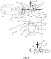
- the control device 10 in a first embodiment illustrated with the figures from 1 to 10, advantageously comprises a metering device comprising first detection means 12, 112, 13, 113, 18, 118, 22, 122 to detect the fluid flow through said flow inlet 2, 211.
- first detection means 12, 112, 13, 113, 18, 118, 22, 122 are, in addition, suitable for recording the presence of a flow of fluid through the inlet 2, 211 and are associated with first measuring means 18, 118, 22, 122 suitable for measuring the time interval, defined as the interval between the starting time and the ending time of the flow through the fluid inlet 2, 211.
- the metering device also comprises second detection means to detect the inlet temperature T i and the outlet temperature T o or to detect exchange temperature T e of at least one of the heat exchange portions 8a, 8b, 8c, 8d, 8e of the radiator 1.
- These second detection means are suitable for recording the incoming temperature T i and the outgoing temperature T o and are associated with second measuring means suitable for measuring the temperature difference between the inlet 2, 211 and outlet 3, 311.
- the metering device also comprises means for calculating the energy consumption, determining the calories consumption, as a function of the flow rate of a boiler connected to the radiator 1. These calculating means are associated with the first and second measuring means and they use the data recorded and measured by the latter.
- the control device preferably comprises control means 6, 61, 7, 711 for controlling the inlet 2, 211 of the radiator 1, designed to open it below a given temperature threshold and to close it above the temperature threshold.
- the first detection means 12, 112, 13, 113, 18, 118, 22, 122 are associated or connected to the control means 6, 61, 7, 711 to detect the opening of the fluid inlet 2, 211.
- These control means may, for instance, consist of a thermostatic valve 6, 61 installed, preferably by means of screws, on the inlet body 4, 41 of the radiator 1.
- the first detection means 12, 112, 13, 113, 18, 118, 22, 122 are suitable for recording the opening of the inlet 2, 211 of the radiator 1.
- the thermostatic valve 6 is associated with a shutter 7 movable between a closed position and an open position of the fluid inlet 2 of the radiator 1.
- the shutter 7 may be contained inside the inlet body 4 of the radiator 1.
- a head 8 on the shutter 7 (numbered only in figures 1 and 3 ) is designed to interact with a portion of the inlet body 4 to close the cross section for the passage of the fluid.
- the shutter 7 is associated with a temperature-sensitive element 110 that at least controls its movement to close the inlet 2 of the radiator 1 when the temperature threshold is exceeded.
- the temperature-sensitive element 110 commands the closing movement of the shutter 7, while the opening movement of the shutter is achieved by elastic elements 11, contained inside the inlet body 4, for instance, and taking effect when the action of the temperature-sensitive element 110 no longer comes to bear on the shutter 7.
- the first detection means comprise a switch 12, preferably a microswitch, associated with a first detection circuit 13.
- the switch is advantageously associated with the shutter 7, or with the temperature-sensitive element 110, of the thermostatic valve 6 so as to modify its open/closed state as a function of the open/closed position of the shutter 7.
- the switch 12, the first recording circuit 13 and the first detection means are contained inside an outer case 14 of the control device suitable for being installed on the inlet body 4 of the radiator 1, e.g. between the thermostatic valve 6 and said inlet body.
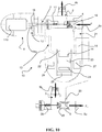
- Figures 9 and 10 show the switch 12 contained inside the thermostatic valve 6, while the first detection means are contained inside the outer case 14 of the control device and the first recording circuit 13 serves as a connection.
- the outer case 14 may extend to cover the inlet body 4.
- the shutter 7 comprises an extension, preferably a sloping plane 15, suitable for changing the state of the switch 12 as a function of the open/closed position of the shutter 7.
- the switch 12 may comprise, for instance, a moving contact 16 ( figure 7 ) suitable for opening the first recording circuit 13 under the action of the shutter 7 (or of the temperature-sensitive element 110) when the inlet 2 of the radiator 1 closes.
- Elastic means 17 may be provided to return the mobile contact 16 to the closed position.
- the first detection circuit 13 may be closed when the inlet 2 of the radiator 1 is closed.
- the function of the shutter 7 and of the elastic means 17 may also be reversed.
- means other than the sloping plane 15 or the temperature-sensitive element 110 may be provided to modify the open/closed state of the moving contact 16.
- the shutter 7 is in the position where the inlet 2 is open and the moving contact 16 is in the position where the first detection circuit 13 is closed.
- the temperature-sensitive element 110 has expanded, pushing the shutter 7 into the closed position and opening the moving contact 16 by means of the sloping plane 15.
- the switch 12 is associated with the temperature-sensitive element 110, or with a thrust portion 110a, by means of an appendage 15a that is arranged so as to change the open/closed state of the switch 12 as a function of the condition of the temperature-sensitive element 110.
- figure 9 shows the appendage 15a detached from the switch 12, which remains closed under the action of the elastic means 17.
- the temperature-sensitive element 110 has expanded, pushing the shutter 7 closed and pushing the moving contact 16 open, opposing the action of the elastic means 17.
- a clock is associated with the first detection circuit 13 to establish the instant when the flow starts and the instant when the flow stops.
- a counter constituting the first measuring means suitable for measuring the time interval, i.e. the time interval between the instant when the flow starts and the instant when it stops.
- the rectangle 18 indicates the clock and the counter.
- thermo probe of inlet 19 records the incoming temperature T i
- thermal probe of outlet 20 records the outgoing temperature T o .
- the thermal probe of inlet 19 is associated with the inlet 2 of the radiator 1.
- the thermal probe of outlet 20 is associated with the outlet 3 of the radiator 1.
- the thermal probe of inlet 19 and the thermal probe of outlet 20 are associated with a second detection circuit 21 associated with second measuring means 22.
- the second measuring means 22 are suitable for measuring the temperature difference between the inlet and the outlet. In the examples shown, this is done by components on an electronic board 22 in the control device 10.
- the thermal probe of inlet 19 and/or the thermal probe of outlet 20 can be inserted in a duct in the radiator 1, e.g. the inlet duct 4 and the outlet duct 5, in contact with the fluid.
- the thermal probe of inlet 19 and/or the thermal probe of outlet 20 can be placed in contact with a duct in the radiator 1, e.g. the inlet duct 4 and the outlet duct 5.
- Figures 1-3 and 8 , 9 show two different positions of the thermal probes directly in contact with the fluid.
- control device 10 may also comprise a display 23 and an input 24 for setting the capacity of the central heating system, for instance, or other parameters, or for resetting the device after any error situations.
- the numeral 25 is used to indicate a radio module suitable for sending the data relating to the flow intervals and the temperature differences to a control unit (not shown).
- the data may be transferred continuously or discretely, providing for the electronic board 22 to record the data over a given period.
- the numerals 26 and 27 indicate two cavities for batteries, which may also have differentiated functions as described below.
- the numeral 28 indicates a further shutter, preferably associated with elastic means 29, installed on the outlet body 5.
- control device 10 with a metering device is described below.
- the first detection means and measuring means record the time interval during which the inlet 2 of the radiator 1 remains open. With reference to the examples shown, the switch 12 is closed when the inlet 2 is open.
- the clock and the counter identify the instant when the first detection circuit 13 is closed and opened, and measure the time interval corresponding to the effective opening of the inlet 2 of the radiator 1.
- the two sensors record the incoming (inlet) T i and outgoing (outlet) T o temperatures, particularly during the time interval corresponding to the effective opening of the inlet 2, and the second measuring means calculate the difference.
- the data relating to the temperature differences between the inlet and the outlet, and to the interval during which the inlet 2 is actually open enable the effective energy consumption to be obtained in terms of the heat absorbed by the environment or in calories consumption.
- the control device 10 with a metering device measures the time interval during which the inlet 2 remains open and the temperature difference between the inlet and the outlet.
- the temperature-sensitive element 110 expands and closes the inlet 2, displacing the shutter 7 ( figure 2 ).
- the movement of the shutter 7 prompts the opening of the first detection circuit 13, which stops the opening time counter.
- the recording of the temperature difference may also be suspended.
- control device 10 may, in addition, comprise an economizer comprising means to prevent the opening of the inlet 2 during certain time periods.
- the economizer is designed to take effect on a shutter operating the inlet 2.
- the economiser is suitable for acting on the shutter 7 of the thermostatic valve 6.
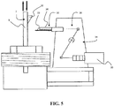
- the control means (to prevent the opening) comprise a cursor 30 movable between a position at rest and a working position, wherein it prevents the shutter 7 from moving from the closed position to the open position.
- the cursor 30 is associated with a control circuit 31, with a user-adjustable input, e.g. the input indicated by the numeral 24.
- the cursor 30 is preferably designed to enable the passage of the shutter 7 from the open position to the closed position.
- the shutter 7 may comprise an extension, such as a sloping plane 32, suitable for interacting with the cursor 30 in the working position.
- the cursor 30 may comprise an elastic element 33 deformable by means of the extension 32 on the shutter 7 during the passage of the shutter from the open position to the closed position.
- the elastic element 33 also constitutes an obstacle to the passage of the shutter from the closed position to the open position ( figures 4-8 ).
- the cursor 30 may comprise the elastic element 33 and a contrasting element 34 designed to prevent the deformation of the elastic element 33 during the phase when the shutter 7 opens (and in the working position of the cursor 30).
- the control circuit 31 preferably comprises an actuator 35, e.g. a linear actuator, associated for instance with a lever mechanism 36 for moving the cursor 30 from the position at rest to the working position and vice versa.
- the actuator 36 may be governed by a relay 37, or the like, associated with the input 24. If there are two batteries, as shown in the figures, one may be used for the actuator and the other for the metering devicve, if any.
- clock/counter 18 the display 23, the radio module 25, and the electronic board 22.
- the clock/counter and the input enable periods to be scheduled during which the cursor must prevent the opening of the inlet 2.
- Figure 5 shows a resting position of the cursor 30, wherein the shutter 7 (the stem 9) can move freely in both directions following the action of the temperature-sensitive element 110, and possibly of the elastic means 11.
- Figure 6 shows a working position of the cursor 30, wherein the shutter 7 (the stem 9) can move to close the inlet 2 (direction A).
- Figure 7 shows the shutter 7 that has advanced further in the direction A to close the inlet 2.
- the sloping plane 32 abuts against the cursor 30 and deforms its elastic element 33.
- the cursor 30 is in the working position and the shutter 7 is in the closed position.
- the shutter 7 is prevented from returning by the cursor 30.
- the elastic element 33 is undeformable due to the presence of the contrasting element 34.
- the cursor moves into the working position. If the shutter 7 of the thermostatic valve 6 was already in the closed position, the cursor 30 prevents it from opening. If the shutter 7 of the thermostatic valve 6 was still in the open position, when the temperature threshold is reached, the temperature-sensitive element 110 pushes the shutter 7 into the closed position without encountering any impediment from the cursor 30. The shutter 7 can subsequently open again only after the cursor has returned to its resting position, which depends on the preset heating schedule.
- the control device 10 may comprise an outer case 14 suitable for installing on the inlet body 4 of the radiator 1, e.g. between the thermostatic valve 6 and the body of the inlet.
- the second embodiment of the control device 11, illustrated in figures 11 and 12 comprises the same technical features of the above described control device, there is only a thermal probe of exchange 119 in a central exchange portion 8c of the radiator 1. No other thermal probe of inlet or of outlet are providing.
- the second detection means detect the exchange temperature T e of the heat exchange portions, in particular in the central exchange portion 8c, warmed by the fluid at exchange temperature T e .
- the detection normally relates to a central position, exchange portion 8c, on the radiator 1, but can also refer to a different position, like the other exchange portion 8a, 8b, 8d, 8e.
- the second measuring means calculate the temperature difference between the heat exchange portion 8a, 8b, 8c, 8d, 8e, preferably the one of these like the central 8c, and at least a comparison temperature.
- the comparison temperature is a fixed temperature that the user can set at the installation of the control device 11 on the radiator 1, or it is a subsequently modified temperature. It is also possible to use the room temperature as the comparison temperature.
- the means to calculate the energy transfer determine the heat consumed based on at least a parameter of the heating system and/or of the radiator 1, as corrective parameters, and based on the temperature difference between the exchange temperature T e and the comparison temperature in a time interval defined as the interval between the starting time and the ending time of the flow through the fluid inlet 211.
- the present invention also relates to a method for the control of radiators 1, convector heaters or the like for a heating system, wherein the radiator 1 comprises a fluid inlet 211 through which the fluid passes at inlet temperature T i , a fluid outlet 3, 311 through which the fluid passes at outlet temperature T o and at least a heat exchange portion 8a, 8b, 8c, 8d, 8e at exchange temperature T e warmed by the fluid at exchange temperature T e .
- the method comprises the following steps:
- the temperature difference is, preferably, calculated between the fluid inlet 2, 211 and the fluid outlet 3, 311, using the inlet temperature T i and the outlet temperature T o .
- the energy consumption determines the calories consumption preferably based on a flow rate of a boiler connected to the radiator 1 and preferably based on said temperature difference in said time interval.
- the incoming temperature T i and the outgoing temperature T u are preferably recorded in direct contact with the fluid, or in contact with the radiator 1.
- the device and the method according to the present invention may undergo modifications and variants, some of which have been mentioned in the course of the present description.
Landscapes
- Chemical & Material Sciences (AREA)
- Engineering & Computer Science (AREA)
- Combustion & Propulsion (AREA)
- Physics & Mathematics (AREA)
- General Physics & Mathematics (AREA)
- Steam Or Hot-Water Central Heating Systems (AREA)
Claims (13)
- Heizungssystem, umfassend einen Radiator (1) und eine Steuerungsvorrichtung (10, 11), wobei die Steuerungsvorrichtung eine Messvorrichtung umfasst, welche umfasst:- erste Erfassungsmittel (12, 112, 13, 113, 18, 118, 22, 122) zum Erfassen der Flüssigkeitsströmung durch einen Flüssigkeitseinlass (2, 211) des Radiators (1);- erste Messmittel (18, 118, 22, 122) für die Zeitspanne zwischen der Startzeit und der Endzeit der Strömung durch den Flüssigkeitseinlass (2, 211), welcher mit den ersten Erfassungsmitteln (12, 112, 13, 113, 18, 118, 22, 122) verbunden ist;- zweite Erfassungsmittel zum Erfassen der Einlasstemperatur (Ti) an dem Flüssigkeitseinlass (2, 211) und der Auslasstemperatur (To) an einem Flüssigkeitsauslass (3, 311) des Radiators (1) und/oder einer Austauschtemperatur (Te) eines Wärmeaustauschabschnitts (8a, 8b, 8c, 8d, 8e) des Radiators (1);- zweite Messmittel, welche mit den zweiten Erfassungsmitteln verbunden sind, zum Berechnen der Temperaturdifferenz zwischen der Einlasstemperatur (Ti) und der Auslasstemperatur (To) bzw. zwischen der Austauschtemperatur (Te) und zumindest einer Vergleichstemperatur;- Mittel zum Berechnen des Energieverbrauchs des Radiators (1), welche mit den ersten (18, 118, 22, 122) und zweiten Messmitteln verbunden sind, auf Basis der gemessenen Zeitspanne und auf Basis der berechneten Temperaturdifferenz.
- Heizungssystem nach Anspruch 1, dadurch gekennzeichnet, dass die zweiten Erfassungsmittel die Austauschtemperatur (Te) erfassen; die zweiten Messmittel die Temperaturdifferenz zwischen der Austauschtemperatur (Te) und zumindest einer Vergleichstemperatur berechnen; die Mittel zum Berechnen der Energieübertragung die verbrauchte Wärme auf Basis zumindest eines Parameters des Heizungssystems und/oder des Radiators und auf Basis der Temperaturdifferenz in der Zeitspanne bestimmen.
- Heizungssystem nach einem oder mehreren der Ansprüche 1 oder 2, dadurch gekennzeichnet, dass die Steuerungsvorrichtung umfasst und/oder verbunden ist mit Steuerungsmitteln (6, 61, 7, 711) für Flüssigkeitseinlass (2, 211), welche geeignet sind, diesen unterhalb einer Schwellentemperatur zu öffnen und diesen oberhalb der Schwellentemperatur zu schließen; wobei die Erfassungsmittel (12, 112, 13, 113, 18, 118, 22, 122) geeignet sind, das Öffnen des Flüssigkeitseinlasses (2, 211) zu erfassen.
- Heizungssystem nach Anspruch 3, dadurch gekennzeichnet, dass die Steuerungsmittel (6, 61, 7, 711) ein Thermostatventil (6) umfassen, welches mit einem Verschluss (7, 711) verbunden ist, welcher zwischen einer Verschlussstellung und einer Öffnungsstellung des Flüssigkeitseinlasses (2, 211) bewegbar ist; wobei der Verschluss (7, 711) mit einem temperaturempfindlichen Element (110, 111) verbunden ist, welches zumindest die Bewegung für die Verschlussstellung des Flüssigkeitseinlasses (2, 211) oberhalb der Schwellentemperatur steuert; wobei die ersten Erfassungsmittel (12, 112, 13, 113, 18, 118, 22, 122) einen Schalter (12, 112) umfassen, welcher mit einer ersten Erfassungsschaltung (13, 113) verbunden ist, wobei der Schalter (12, 112) seinen Zustand von Öffnen/Schließen abhängig von der Stellung von Öffnen/Schließen des Verschlusses (7, 711) ändert.
- Heizungssystem nach Anspruch 4, dadurch gekennzeichnet, dass der Verschluss (7, 711) eine Erweiterung (15, 115) umfasst, welche geeignet ist, den Status des Schalters (12, 112) abhängig von der Stellung von Öffnen/Schließen des Verschlusses (7, 711) zu ändern, oder dass das temperaturempfindliche Element (110, 111) einen Fortsatz (15a) umfasst, welcher geeignet ist, den Status von Öffnen/Schließen des Schalters (12, 112) abhängig von dem Zustand des temperaturempfindlichen Elements (110, 111) zu ändern.
- Heizungssystem nach Anspruch 5, dadurch gekennzeichnet, dass die ersten Erfassungsmittel zumindest eine mit der ersten Erfassungsschaltung (13, 113) verbundene Uhr (18, 118) zum Definieren der Startzeit und der Endzeit der Strömung umfassen und zumindest einen Zähler (18, 118) zum Definieren der Zeitspanne zwischen der Startzeit und der Endzeit der Strömung umfassen.
- Heizungssystem nach einem oder mehreren der Ansprüche von 1 bis 6, dadurch gekennzeichnet, dass die zweiten Erfassungsmittel eine Thermosonde des Einlasses (19) und eine Thermosonde des Auslasses (20) umfassen, welche jeweils mit dem Einlass (2) bzw. dem Auslass (3) des Radiators verbunden sind; wobei die Thermosonde des Einlasses (19) und die Thermosonde des Auslasses (20) mit einer zweiten Erfassungsschaltung (21) verbunden sind, welche mit den zweiten Messmitteln (22) verbunden ist.
- Heizungssystem nach Anspruch 7, dadurch gekennzeichnet, dass die Thermosonde des Einlasses (19) und/oder eine Thermosonde des Auslasses (20) in den Radiator in Kontakt mit der Flüssigkeit eingeführt werden oder in Kontakt mit dem Radiator platziert werden.
- Heizungssystem nach einem oder mehreren Ansprüchen von 4 bis 8, dadurch gekennzeichnet, dass die Steuerungsvorrichtung eine Economiservorrichtung umfasst, welche Mittel zum Verhindern des Öffnens des Einlasses (2, 211) zu bestimmten Zeiten umfasst; wobei die Mittel zum Verhindern des Öffnens einen Schieber (30, 130) umfassen, welcher zwischen einer Ruhestellung und einer Arbeitsstellung bewegbar ist; wobei der Schieber (30, 130) mit einer Steuerungsschaltung (31, 131) verbunden ist, für welche ein von einem Benutzer festgelegter Eingang (24, 124) bereitgestellt ist.
- Heizungssystem nach Anspruch 11, dadurch gekennzeichnet, dass der Schieber (30, 130) in der Arbeitsstellung dem Verschluss (7, 711) erlaubt, von einer geöffneten Stellung in eine geschlossene Stellung überzugehen; wobei der Verschluss (7, 711) eine Erweiterung (32, 132) beinhaltet, welche geeignet ist, mit dem Schieber (30, 130) zu interagieren, wenn in einer Arbeitsstellung; wobei der Schieber (30, 130) ein elastisches Element (33) umfasst, welches mittels der Erweiterung (32, 132) während des Übergangs des Verschlusses (7, 711) von der geöffneten Stellung in die geschlossene Stellung deformierbar ist, wobei das elastische Element (33) weiter ein Hindernis für den Verschluss (7, 711) beim Übergang von der geschlossenen Stellung in die geöffnet Stellung definiert.
- Heizungssystem nach einem oder mehreren der Ansprüche von 3 bis 10, dadurch gekennzeichnet, dass die Messvorrichtung zwischen dem Radiator und dem Thermostatventil (6) eingeschoben ist.
- Verfahren für die Berechnung des Energieverbrauchs und/oder der Energieübertragung von Radiatoren (1) für ein Heizungssystem, welches dadurch gekennzeichnet ist, dass es die folgenden Schritte umfasst:- Erfassen einer Flüssigkeitsströmung durch einen Flüssigkeitseinlass (2, 211) der Radiatoren (1) und Messen der Zeitspanne zwischen der Startzeit und der Endzeit der Strömung durch den Flüssigkeitseinlass (2, 211);- Erkennen einer Einlasstemperatur (Ti) und einer Auslasstemperatur (To) und/oder einer Austauschtemperatur (Te) und Berechnen der Temperaturdifferenz zwischen der Einlasstemperatur (Ti) und der Auslasstemperatur (To) oder zwischen der Austauschtemperatur (Te) und zumindest einer Vergleichstemperatur;- Berechnen des Energieverbrauchs des Radiators (1) mittels Verwenden zumindest der gemessenen Zeitspanne und der berechneten Temperaturdifferenz.
- Verfahren nach Anspruch 13, dadurch gekennzeichnet, dass die Temperaturdifferenz zwischen dem Flüssigkeitseinlass (2) und einem Flüssigkeitsauslass (3) der Radiatoren (1) berechnet wird, mittels Verwenden der Einlasstemperatur (Ti) und der Auslasstemperatur (To); wobei der Energieverbrauch den Kalorienverbrauch auf Basis einer Strömungsrate eines an den Radiator (1) angeschlossenen Boilers und auf Basis der Temperaturdifferenz in der Zeitspanne bestimmt.
Applications Claiming Priority (1)
| Application Number | Priority Date | Filing Date | Title |
|---|---|---|---|
| ITMI20100194 | 2010-02-10 |
Publications (2)
| Publication Number | Publication Date |
|---|---|
| EP2354775A1 EP2354775A1 (de) | 2011-08-10 |
| EP2354775B1 true EP2354775B1 (de) | 2018-08-08 |
Family
ID=42740300
Family Applications (1)
| Application Number | Title | Priority Date | Filing Date |
|---|---|---|---|
| EP11153907.8A Active EP2354775B1 (de) | 2010-02-10 | 2011-02-09 | Heizkörpersteuervorrichtung |
Country Status (2)
| Country | Link |
|---|---|
| EP (1) | EP2354775B1 (de) |
| ES (1) | ES2694396T3 (de) |
Families Citing this family (4)
| Publication number | Priority date | Publication date | Assignee | Title |
|---|---|---|---|---|
| ITBS20150067A1 (it) * | 2015-04-15 | 2016-10-15 | Ivar Spa | Dispositivo per la regolazione della temperatura e la ripartizione dei consumi di un elemento riscaldante |
| JP6458649B2 (ja) * | 2015-06-01 | 2019-01-30 | 富士通株式会社 | 冷却装置、冷却方法及び情報処理システム |
| IT201700074431A1 (it) * | 2017-07-05 | 2019-01-05 | Armando Garibaldi | Sistema integrativo gmv-cid ad alta efficienza energetica per radiatori e caldaie a condensazione (geometria metrica variabile)(contabilizzazione integrata diretta) |
| CN114812864B (zh) * | 2022-06-23 | 2022-11-08 | 江苏日盈电子股份有限公司 | 一种汽车发动机用进气温度传感器及其装配机构 |
Family Cites Families (4)
| Publication number | Priority date | Publication date | Assignee | Title |
|---|---|---|---|---|
| US3995686A (en) * | 1975-06-05 | 1976-12-07 | Laube Herbert L | Energy consumption indicating system |
| DE3050838C2 (de) * | 1980-03-20 | 1988-05-19 | Ziegler, Horst, Prof. Dr., 4790 Paderborn, De | |
| IT1159619B (it) * | 1983-09-23 | 1987-03-04 | Indesit | Apparecchio contatore di energia termica ceduta da un fluido passante in un tratto di condotto |
| US20050056799A1 (en) * | 2003-09-11 | 2005-03-17 | Malone Steven J. | Valves having a thermostatic actuator controlled by a peltier device |
-
2011
- 2011-02-09 EP EP11153907.8A patent/EP2354775B1/de active Active
- 2011-02-09 ES ES11153907.8T patent/ES2694396T3/es active Active
Non-Patent Citations (1)
| Title |
|---|
| None * |
Also Published As
| Publication number | Publication date |
|---|---|
| ES2694396T3 (es) | 2018-12-20 |
| EP2354775A1 (de) | 2011-08-10 |
Similar Documents
| Publication | Publication Date | Title |
|---|---|---|
| DK2880345T3 (en) | ADVANCED VALVE ACTIVATION SYSTEM WITH INTEGRATED FREEZE PROTECTION | |
| US7792659B2 (en) | Device and a method for measurement of energy for heating tap water separated from the buildings heating energy-usage | |
| EP2354775B1 (de) | Heizkörpersteuervorrichtung | |
| EP0830649B1 (de) | Thermostatsystem mit optimierter ansteigsrate der wiederzuerreichenden temperatur | |
| RU2573378C2 (ru) | Устройство и способ управления открытием клапана в системе hvac | |
| KR101730683B1 (ko) | 빌딩 내의 복수의 룸의 온도를 조절하기 위한 방법 및 장치 | |
| EP3589930B1 (de) | Auswertung von heizflüssigkeitsdruckabfällen in einem hydronischen heizsystem | |
| CA2635003C (en) | Modulating boiler system | |
| CA2677047C (en) | System for controlling the heating of housing units in a building | |
| EP2466413B1 (de) | Ventilanordnung und Verfahren zum Betrieb eines Ventils | |
| US11281201B2 (en) | Air conditioner and methods of operation having a learning event | |
| US10527297B2 (en) | Domestic hot water installation | |
| DK3098575T3 (en) | Hot water meter and measuring method therefore | |
| US7168628B2 (en) | Control valve monitoring | |
| ES2878139T5 (en) | Heating cost distributor for detecting the amount of heat output by a radiator | |
| GB2382646A (en) | Water heating apparatus with temperature control | |
| EP3276266B1 (de) | Verfahren zur steuerung eines heiz- oder kühlsystems und heiz- oder kühlsystem | |
| US11347246B2 (en) | Water heater appliances and methods for controlling a mixing valve with a park period | |
| KR100757302B1 (ko) | 온돌용 난방장치 | |
| CN102483315A (zh) | 用于计量由散热器、对流加热器等发出的热能,特别用于分配加热和/或调节成本的装置 | |
| EP2442038A2 (de) | Integrierte Vorrichtung zur Erfassung der von Heizkörpern abgegebenene Wärme und zum Steuern eines Thermostatventils | |
| WO2019145873A1 (en) | Device and method for the temperature adjustment of a heating element | |
| KR101508475B1 (ko) | 하나의 열원을 사용하는 다수 세대의 난방 ems 시스템 | |
| KR20100116091A (ko) | 열량계 일체형 각방 개별난방 시스템 | |
| DK202000203A1 (en) | Control system and method for controlling a control valve of a hydrodynamic system using an actuator |
Legal Events
| Date | Code | Title | Description |
|---|---|---|---|
| PUAI | Public reference made under article 153(3) epc to a published international application that has entered the european phase |
Free format text: ORIGINAL CODE: 0009012 |
|
| AK | Designated contracting states |
Kind code of ref document: A1 Designated state(s): AL AT BE BG CH CY CZ DE DK EE ES FI FR GB GR HR HU IE IS IT LI LT LU LV MC MK MT NL NO PL PT RO RS SE SI SK SM TR |
|
| AX | Request for extension of the european patent |
Extension state: BA ME |
|
| 17P | Request for examination filed |
Effective date: 20120207 |
|
| 17Q | First examination report despatched |
Effective date: 20160129 |
|
| STAA | Information on the status of an ep patent application or granted ep patent |
Free format text: STATUS: EXAMINATION IS IN PROGRESS |
|
| GRAP | Despatch of communication of intention to grant a patent |
Free format text: ORIGINAL CODE: EPIDOSNIGR1 |
|
| STAA | Information on the status of an ep patent application or granted ep patent |
Free format text: STATUS: GRANT OF PATENT IS INTENDED |
|
| INTG | Intention to grant announced |
Effective date: 20180328 |
|
| GRAS | Grant fee paid |
Free format text: ORIGINAL CODE: EPIDOSNIGR3 |
|
| GRAA | (expected) grant |
Free format text: ORIGINAL CODE: 0009210 |
|
| STAA | Information on the status of an ep patent application or granted ep patent |
Free format text: STATUS: THE PATENT HAS BEEN GRANTED |
|
| AK | Designated contracting states |
Kind code of ref document: B1 Designated state(s): AL AT BE BG CH CY CZ DE DK EE ES FI FR GB GR HR HU IE IS IT LI LT LU LV MC MK MT NL NO PL PT RO RS SE SI SK SM TR |
|
| REG | Reference to a national code |
Ref country code: GB Ref legal event code: FG4D |
|
| REG | Reference to a national code |
Ref country code: CH Ref legal event code: EP Ref country code: AT Ref legal event code: REF Ref document number: 1027557 Country of ref document: AT Kind code of ref document: T Effective date: 20180815 |
|
| REG | Reference to a national code |
Ref country code: IE Ref legal event code: FG4D |
|
| REG | Reference to a national code |
Ref country code: DE Ref legal event code: R096 Ref document number: 602011050735 Country of ref document: DE |
|
| REG | Reference to a national code |
Ref country code: NL Ref legal event code: MP Effective date: 20180808 |
|
| REG | Reference to a national code |
Ref country code: ES Ref legal event code: FG2A Ref document number: 2694396 Country of ref document: ES Kind code of ref document: T3 Effective date: 20181220 |
|
| REG | Reference to a national code |
Ref country code: LT Ref legal event code: MG4D |
|
| REG | Reference to a national code |
Ref country code: AT Ref legal event code: MK05 Ref document number: 1027557 Country of ref document: AT Kind code of ref document: T Effective date: 20180808 |
|
| PG25 | Lapsed in a contracting state [announced via postgrant information from national office to epo] |
Ref country code: FI Free format text: LAPSE BECAUSE OF FAILURE TO SUBMIT A TRANSLATION OF THE DESCRIPTION OR TO PAY THE FEE WITHIN THE PRESCRIBED TIME-LIMIT Effective date: 20180808 Ref country code: IS Free format text: LAPSE BECAUSE OF FAILURE TO SUBMIT A TRANSLATION OF THE DESCRIPTION OR TO PAY THE FEE WITHIN THE PRESCRIBED TIME-LIMIT Effective date: 20181208 Ref country code: LT Free format text: LAPSE BECAUSE OF FAILURE TO SUBMIT A TRANSLATION OF THE DESCRIPTION OR TO PAY THE FEE WITHIN THE PRESCRIBED TIME-LIMIT Effective date: 20180808 Ref country code: RS Free format text: LAPSE BECAUSE OF FAILURE TO SUBMIT A TRANSLATION OF THE DESCRIPTION OR TO PAY THE FEE WITHIN THE PRESCRIBED TIME-LIMIT Effective date: 20180808 Ref country code: BG Free format text: LAPSE BECAUSE OF FAILURE TO SUBMIT A TRANSLATION OF THE DESCRIPTION OR TO PAY THE FEE WITHIN THE PRESCRIBED TIME-LIMIT Effective date: 20181108 Ref country code: AT Free format text: LAPSE BECAUSE OF FAILURE TO SUBMIT A TRANSLATION OF THE DESCRIPTION OR TO PAY THE FEE WITHIN THE PRESCRIBED TIME-LIMIT Effective date: 20180808 Ref country code: NL Free format text: LAPSE BECAUSE OF FAILURE TO SUBMIT A TRANSLATION OF THE DESCRIPTION OR TO PAY THE FEE WITHIN THE PRESCRIBED TIME-LIMIT Effective date: 20180808 Ref country code: NO Free format text: LAPSE BECAUSE OF FAILURE TO SUBMIT A TRANSLATION OF THE DESCRIPTION OR TO PAY THE FEE WITHIN THE PRESCRIBED TIME-LIMIT Effective date: 20181108 Ref country code: GR Free format text: LAPSE BECAUSE OF FAILURE TO SUBMIT A TRANSLATION OF THE DESCRIPTION OR TO PAY THE FEE WITHIN THE PRESCRIBED TIME-LIMIT Effective date: 20181109 Ref country code: SE Free format text: LAPSE BECAUSE OF FAILURE TO SUBMIT A TRANSLATION OF THE DESCRIPTION OR TO PAY THE FEE WITHIN THE PRESCRIBED TIME-LIMIT Effective date: 20180808 |
|
| PG25 | Lapsed in a contracting state [announced via postgrant information from national office to epo] |
Ref country code: AL Free format text: LAPSE BECAUSE OF FAILURE TO SUBMIT A TRANSLATION OF THE DESCRIPTION OR TO PAY THE FEE WITHIN THE PRESCRIBED TIME-LIMIT Effective date: 20180808 Ref country code: LV Free format text: LAPSE BECAUSE OF FAILURE TO SUBMIT A TRANSLATION OF THE DESCRIPTION OR TO PAY THE FEE WITHIN THE PRESCRIBED TIME-LIMIT Effective date: 20180808 Ref country code: HR Free format text: LAPSE BECAUSE OF FAILURE TO SUBMIT A TRANSLATION OF THE DESCRIPTION OR TO PAY THE FEE WITHIN THE PRESCRIBED TIME-LIMIT Effective date: 20180808 |
|
| REG | Reference to a national code |
Ref country code: CH Ref legal event code: NV Representative=s name: VALIPAT S.A. GEVERS SA, CH |
|
| REG | Reference to a national code |
Ref country code: CH Ref legal event code: PCAR Free format text: NEW ADDRESS: RUE DES NOYERS 11, 2000 NEUCHATEL (CH) |
|
| PG25 | Lapsed in a contracting state [announced via postgrant information from national office to epo] |
Ref country code: CZ Free format text: LAPSE BECAUSE OF FAILURE TO SUBMIT A TRANSLATION OF THE DESCRIPTION OR TO PAY THE FEE WITHIN THE PRESCRIBED TIME-LIMIT Effective date: 20180808 Ref country code: EE Free format text: LAPSE BECAUSE OF FAILURE TO SUBMIT A TRANSLATION OF THE DESCRIPTION OR TO PAY THE FEE WITHIN THE PRESCRIBED TIME-LIMIT Effective date: 20180808 Ref country code: RO Free format text: LAPSE BECAUSE OF FAILURE TO SUBMIT A TRANSLATION OF THE DESCRIPTION OR TO PAY THE FEE WITHIN THE PRESCRIBED TIME-LIMIT Effective date: 20180808 |
|
| REG | Reference to a national code |
Ref country code: DE Ref legal event code: R097 Ref document number: 602011050735 Country of ref document: DE |
|
| PG25 | Lapsed in a contracting state [announced via postgrant information from national office to epo] |
Ref country code: DK Free format text: LAPSE BECAUSE OF FAILURE TO SUBMIT A TRANSLATION OF THE DESCRIPTION OR TO PAY THE FEE WITHIN THE PRESCRIBED TIME-LIMIT Effective date: 20180808 Ref country code: SM Free format text: LAPSE BECAUSE OF FAILURE TO SUBMIT A TRANSLATION OF THE DESCRIPTION OR TO PAY THE FEE WITHIN THE PRESCRIBED TIME-LIMIT Effective date: 20180808 Ref country code: SK Free format text: LAPSE BECAUSE OF FAILURE TO SUBMIT A TRANSLATION OF THE DESCRIPTION OR TO PAY THE FEE WITHIN THE PRESCRIBED TIME-LIMIT Effective date: 20180808 |
|
| PLBE | No opposition filed within time limit |
Free format text: ORIGINAL CODE: 0009261 |
|
| STAA | Information on the status of an ep patent application or granted ep patent |
Free format text: STATUS: NO OPPOSITION FILED WITHIN TIME LIMIT |
|
| 26N | No opposition filed |
Effective date: 20190509 |
|
| PG25 | Lapsed in a contracting state [announced via postgrant information from national office to epo] |
Ref country code: PL Free format text: LAPSE BECAUSE OF FAILURE TO SUBMIT A TRANSLATION OF THE DESCRIPTION OR TO PAY THE FEE WITHIN THE PRESCRIBED TIME-LIMIT Effective date: 20180808 |
|
| PG25 | Lapsed in a contracting state [announced via postgrant information from national office to epo] |
Ref country code: SI Free format text: LAPSE BECAUSE OF FAILURE TO SUBMIT A TRANSLATION OF THE DESCRIPTION OR TO PAY THE FEE WITHIN THE PRESCRIBED TIME-LIMIT Effective date: 20180808 |
|
| GBPC | Gb: european patent ceased through non-payment of renewal fee |
Effective date: 20190209 |
|
| PG25 | Lapsed in a contracting state [announced via postgrant information from national office to epo] |
Ref country code: MC Free format text: LAPSE BECAUSE OF FAILURE TO SUBMIT A TRANSLATION OF THE DESCRIPTION OR TO PAY THE FEE WITHIN THE PRESCRIBED TIME-LIMIT Effective date: 20180808 Ref country code: LU Free format text: LAPSE BECAUSE OF NON-PAYMENT OF DUE FEES Effective date: 20190209 |
|
| REG | Reference to a national code |
Ref country code: BE Ref legal event code: MM Effective date: 20190228 |
|
| REG | Reference to a national code |
Ref country code: IE Ref legal event code: MM4A |
|
| PG25 | Lapsed in a contracting state [announced via postgrant information from national office to epo] |
Ref country code: GB Free format text: LAPSE BECAUSE OF NON-PAYMENT OF DUE FEES Effective date: 20190209 Ref country code: IE Free format text: LAPSE BECAUSE OF NON-PAYMENT OF DUE FEES Effective date: 20190209 |
|
| PG25 | Lapsed in a contracting state [announced via postgrant information from national office to epo] |
Ref country code: BE Free format text: LAPSE BECAUSE OF NON-PAYMENT OF DUE FEES Effective date: 20190228 |
|
| PG25 | Lapsed in a contracting state [announced via postgrant information from national office to epo] |
Ref country code: TR Free format text: LAPSE BECAUSE OF FAILURE TO SUBMIT A TRANSLATION OF THE DESCRIPTION OR TO PAY THE FEE WITHIN THE PRESCRIBED TIME-LIMIT Effective date: 20180808 |
|
| PG25 | Lapsed in a contracting state [announced via postgrant information from national office to epo] |
Ref country code: PT Free format text: LAPSE BECAUSE OF FAILURE TO SUBMIT A TRANSLATION OF THE DESCRIPTION OR TO PAY THE FEE WITHIN THE PRESCRIBED TIME-LIMIT Effective date: 20181208 Ref country code: MT Free format text: LAPSE BECAUSE OF NON-PAYMENT OF DUE FEES Effective date: 20190209 |
|
| PGFP | Annual fee paid to national office [announced via postgrant information from national office to epo] |
Ref country code: CH Payment date: 20210303 Year of fee payment: 11 Ref country code: FR Payment date: 20210223 Year of fee payment: 11 |
|
| PG25 | Lapsed in a contracting state [announced via postgrant information from national office to epo] |
Ref country code: CY Free format text: LAPSE BECAUSE OF FAILURE TO SUBMIT A TRANSLATION OF THE DESCRIPTION OR TO PAY THE FEE WITHIN THE PRESCRIBED TIME-LIMIT Effective date: 20180808 |
|
| PGFP | Annual fee paid to national office [announced via postgrant information from national office to epo] |
Ref country code: ES Payment date: 20210301 Year of fee payment: 11 Ref country code: DE Payment date: 20210225 Year of fee payment: 11 |
|
| PG25 | Lapsed in a contracting state [announced via postgrant information from national office to epo] |
Ref country code: HU Free format text: LAPSE BECAUSE OF FAILURE TO SUBMIT A TRANSLATION OF THE DESCRIPTION OR TO PAY THE FEE WITHIN THE PRESCRIBED TIME-LIMIT; INVALID AB INITIO Effective date: 20110209 |
|
| PG25 | Lapsed in a contracting state [announced via postgrant information from national office to epo] |
Ref country code: MK Free format text: LAPSE BECAUSE OF FAILURE TO SUBMIT A TRANSLATION OF THE DESCRIPTION OR TO PAY THE FEE WITHIN THE PRESCRIBED TIME-LIMIT Effective date: 20180808 |
|
| REG | Reference to a national code |
Ref country code: DE Ref legal event code: R119 Ref document number: 602011050735 Country of ref document: DE |
|
| REG | Reference to a national code |
Ref country code: CH Ref legal event code: PL |
|
| PG25 | Lapsed in a contracting state [announced via postgrant information from national office to epo] |
Ref country code: FR Free format text: LAPSE BECAUSE OF NON-PAYMENT OF DUE FEES Effective date: 20220228 |
|
| PG25 | Lapsed in a contracting state [announced via postgrant information from national office to epo] |
Ref country code: LI Free format text: LAPSE BECAUSE OF NON-PAYMENT OF DUE FEES Effective date: 20220228 Ref country code: DE Free format text: LAPSE BECAUSE OF NON-PAYMENT OF DUE FEES Effective date: 20220901 Ref country code: CH Free format text: LAPSE BECAUSE OF NON-PAYMENT OF DUE FEES Effective date: 20220228 |
|
| REG | Reference to a national code |
Ref country code: ES Ref legal event code: FD2A Effective date: 20230331 |
|
| PG25 | Lapsed in a contracting state [announced via postgrant information from national office to epo] |
Ref country code: ES Free format text: LAPSE BECAUSE OF NON-PAYMENT OF DUE FEES Effective date: 20220210 |
|
| PGFP | Annual fee paid to national office [announced via postgrant information from national office to epo] |
Ref country code: IT Payment date: 20260204 Year of fee payment: 16 |