EP2354720B1 - Water circulation system associated with refrigerant cycle - Google Patents
Water circulation system associated with refrigerant cycle Download PDFInfo
- Publication number
- EP2354720B1 EP2354720B1 EP10250798.5A EP10250798A EP2354720B1 EP 2354720 B1 EP2354720 B1 EP 2354720B1 EP 10250798 A EP10250798 A EP 10250798A EP 2354720 B1 EP2354720 B1 EP 2354720B1
- Authority
- EP
- European Patent Office
- Prior art keywords
- refrigerant
- water
- control unit
- flow control
- heat exchanger
- Prior art date
- Legal status (The legal status is an assumption and is not a legal conclusion. Google has not performed a legal analysis and makes no representation as to the accuracy of the status listed.)
- Active
Links
- XLYOFNOQVPJJNP-UHFFFAOYSA-N water Substances O XLYOFNOQVPJJNP-UHFFFAOYSA-N 0.000 title claims description 421
- 239000003507 refrigerant Substances 0.000 title claims description 414
- 238000010438 heat treatment Methods 0.000 claims description 100
- 230000006835 compression Effects 0.000 claims description 82
- 238000007906 compression Methods 0.000 claims description 82
- 238000010257 thawing Methods 0.000 claims description 64
- 238000001816 cooling Methods 0.000 claims description 63
- 230000000063 preceeding effect Effects 0.000 claims 3
- 239000008400 supply water Substances 0.000 claims 1
- 239000000543 intermediate Substances 0.000 description 65
- 238000010586 diagram Methods 0.000 description 16
- 238000000034 method Methods 0.000 description 15
- 238000013459 approach Methods 0.000 description 8
- 238000001704 evaporation Methods 0.000 description 8
- 230000008020 evaporation Effects 0.000 description 8
- 238000007599 discharging Methods 0.000 description 4
- 239000012530 fluid Substances 0.000 description 4
- 230000015556 catabolic process Effects 0.000 description 2
- 238000006731 degradation reaction Methods 0.000 description 2
- 238000010521 absorption reaction Methods 0.000 description 1
- 230000005494 condensation Effects 0.000 description 1
- 238000009833 condensation Methods 0.000 description 1
- 239000000498 cooling water Substances 0.000 description 1
- 238000004851 dishwashing Methods 0.000 description 1
- 230000000694 effects Effects 0.000 description 1
- 230000005611 electricity Effects 0.000 description 1
- 239000003673 groundwater Substances 0.000 description 1
- 230000007257 malfunction Effects 0.000 description 1
- 230000002265 prevention Effects 0.000 description 1
- 239000000126 substance Substances 0.000 description 1
- 238000005406 washing Methods 0.000 description 1
Images






Classifications
-
- F—MECHANICAL ENGINEERING; LIGHTING; HEATING; WEAPONS; BLASTING
- F25—REFRIGERATION OR COOLING; COMBINED HEATING AND REFRIGERATION SYSTEMS; HEAT PUMP SYSTEMS; MANUFACTURE OR STORAGE OF ICE; LIQUEFACTION SOLIDIFICATION OF GASES
- F25B—REFRIGERATION MACHINES, PLANTS OR SYSTEMS; COMBINED HEATING AND REFRIGERATION SYSTEMS; HEAT PUMP SYSTEMS
- F25B29/00—Combined heating and refrigeration systems, e.g. operating alternately or simultaneously
-
- F—MECHANICAL ENGINEERING; LIGHTING; HEATING; WEAPONS; BLASTING
- F25—REFRIGERATION OR COOLING; COMBINED HEATING AND REFRIGERATION SYSTEMS; HEAT PUMP SYSTEMS; MANUFACTURE OR STORAGE OF ICE; LIQUEFACTION SOLIDIFICATION OF GASES
- F25B—REFRIGERATION MACHINES, PLANTS OR SYSTEMS; COMBINED HEATING AND REFRIGERATION SYSTEMS; HEAT PUMP SYSTEMS
- F25B7/00—Compression machines, plants or systems, with cascade operation, i.e. with two or more circuits, the heat from the condenser of one circuit being absorbed by the evaporator of the next circuit
-
- F—MECHANICAL ENGINEERING; LIGHTING; HEATING; WEAPONS; BLASTING
- F25—REFRIGERATION OR COOLING; COMBINED HEATING AND REFRIGERATION SYSTEMS; HEAT PUMP SYSTEMS; MANUFACTURE OR STORAGE OF ICE; LIQUEFACTION SOLIDIFICATION OF GASES
- F25B—REFRIGERATION MACHINES, PLANTS OR SYSTEMS; COMBINED HEATING AND REFRIGERATION SYSTEMS; HEAT PUMP SYSTEMS
- F25B25/00—Machines, plants or systems, using a combination of modes of operation covered by two or more of the groups F25B1/00 - F25B23/00
- F25B25/005—Machines, plants or systems, using a combination of modes of operation covered by two or more of the groups F25B1/00 - F25B23/00 using primary and secondary systems
-
- F—MECHANICAL ENGINEERING; LIGHTING; HEATING; WEAPONS; BLASTING
- F25—REFRIGERATION OR COOLING; COMBINED HEATING AND REFRIGERATION SYSTEMS; HEAT PUMP SYSTEMS; MANUFACTURE OR STORAGE OF ICE; LIQUEFACTION SOLIDIFICATION OF GASES
- F25B—REFRIGERATION MACHINES, PLANTS OR SYSTEMS; COMBINED HEATING AND REFRIGERATION SYSTEMS; HEAT PUMP SYSTEMS
- F25B47/00—Arrangements for preventing or removing deposits or corrosion, not provided for in another subclass
- F25B47/02—Defrosting cycles
-
- F—MECHANICAL ENGINEERING; LIGHTING; HEATING; WEAPONS; BLASTING
- F25—REFRIGERATION OR COOLING; COMBINED HEATING AND REFRIGERATION SYSTEMS; HEAT PUMP SYSTEMS; MANUFACTURE OR STORAGE OF ICE; LIQUEFACTION SOLIDIFICATION OF GASES
- F25B—REFRIGERATION MACHINES, PLANTS OR SYSTEMS; COMBINED HEATING AND REFRIGERATION SYSTEMS; HEAT PUMP SYSTEMS
- F25B49/00—Arrangement or mounting of control or safety devices
- F25B49/02—Arrangement or mounting of control or safety devices for compression type machines, plants or systems
-
- F—MECHANICAL ENGINEERING; LIGHTING; HEATING; WEAPONS; BLASTING
- F25—REFRIGERATION OR COOLING; COMBINED HEATING AND REFRIGERATION SYSTEMS; HEAT PUMP SYSTEMS; MANUFACTURE OR STORAGE OF ICE; LIQUEFACTION SOLIDIFICATION OF GASES
- F25B—REFRIGERATION MACHINES, PLANTS OR SYSTEMS; COMBINED HEATING AND REFRIGERATION SYSTEMS; HEAT PUMP SYSTEMS
- F25B13/00—Compression machines, plants or systems, with reversible cycle
-
- F—MECHANICAL ENGINEERING; LIGHTING; HEATING; WEAPONS; BLASTING
- F25—REFRIGERATION OR COOLING; COMBINED HEATING AND REFRIGERATION SYSTEMS; HEAT PUMP SYSTEMS; MANUFACTURE OR STORAGE OF ICE; LIQUEFACTION SOLIDIFICATION OF GASES
- F25B—REFRIGERATION MACHINES, PLANTS OR SYSTEMS; COMBINED HEATING AND REFRIGERATION SYSTEMS; HEAT PUMP SYSTEMS
- F25B2313/00—Compression machines, plants or systems with reversible cycle not otherwise provided for
- F25B2313/031—Sensor arrangements
- F25B2313/0315—Temperature sensors near the outdoor heat exchanger
-
- F—MECHANICAL ENGINEERING; LIGHTING; HEATING; WEAPONS; BLASTING
- F25—REFRIGERATION OR COOLING; COMBINED HEATING AND REFRIGERATION SYSTEMS; HEAT PUMP SYSTEMS; MANUFACTURE OR STORAGE OF ICE; LIQUEFACTION SOLIDIFICATION OF GASES
- F25B—REFRIGERATION MACHINES, PLANTS OR SYSTEMS; COMBINED HEATING AND REFRIGERATION SYSTEMS; HEAT PUMP SYSTEMS
- F25B47/00—Arrangements for preventing or removing deposits or corrosion, not provided for in another subclass
- F25B47/02—Defrosting cycles
- F25B47/022—Defrosting cycles hot gas defrosting
- F25B47/025—Defrosting cycles hot gas defrosting by reversing the cycle
Definitions
- the present invention relates to a water circulation system associated with a refrigerant cycle.
- Embodiments perform a hot water supplying function and cooling and heating functions in association with the refrigerant cycle.
- indoor cooling and heating are performed by an air conditioner using the refrigerant cycle and supplying hot water is performed by a boiler with an additional heating source.
- the air conditioner includes an outdoor unit installed in an outdoor area and an indoor unit installed in an indoor area.
- the outdoor unit includes a compressor compressing refrigerant, an outdoor heat exchanger for exchanging heat of outdoor air with the refrigerant, and a decompressing device and the indoor unit includes an indoor heat exchanger for exchanging heat of indoor air with the refrigerant.
- any one of the outdoor heat exchanger and the indoor heat exchanger serves as a condenser and the other one serves as an evaporator and the compressor, the outdoor heat exchanger, the decompressing device, and the indoor heat exchanger perform a refrigerant cycle.
- the boiler generates heat by using oil, gas, or electricity and heats water to supply hot water or perform floor heating.
- CN 2570706 describes a heating device that transforms groundwater low-grade heat into high-grade heat using low and high temperature water circulation cycles.
- the present invention provides a water circulation system associated with a refrigerant cycle that can selectively heat exchange water for cooling and heating and hot water supplying with at least one of a first refrigerant and a second refrigerant, and in particular a water circulation system associated with the a refrigerant cycle according to the appended claims.
- the present invention can improve the operation efficiency of the water circulation system associated with the refrigerant cycle.
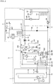
- FIG. 1 is a configuration diagram of a first embodiment of a water circulation system associated with a refrigerant cycle according to the present invention.
- the water circulation system S associated with the refrigerant cycle includes a first refrigerant circulation unit where first refrigerant exchanging heat with outdoor air flows to perform the refrigerant cycle, a second refrigerant circulation unit where second refrigerant exchanging heat with the first refrigerant flows to perform the refrigerant cycle, and a water circulation unit where water for at least one of indoor heating/cooling and hot water supplying.
- the refrigerant cycle means transmitting the heat by repetitively performing compression, condensation, expansion, and evaporation processes.
- the water circulation system S associated with the refrigerant cycle includes an outdoor unit 1 where an outdoor heat exchanger 13 exchanging the first refrigerant and the outdoor air with each other is installed and an intermediator 2 that intermediates the outdoor 1 with the water circulation unit and includes a water refrigerant heat exchanger 23 exchanging heat between the second refrigerant and water.
- the first refrigerant circulation unit includes the outdoor heat exchanger 13, a first compressor 11 compressing the first refrigerant, a first expansion unit 14 expanding the first refrigerant, a first flow switch 12 switching a flow direction of the first refrigerant, an intermediate heat exchanger 25 exchanging heat between the first refrigerant and the second refrigerant, and a first refrigerant pipe 15. That is, the first refrigerant performs the refrigerant cycle while sequentially circulating any one of the first compressor 11, the outdoor heat exchanger 13, and the intermediate heat exchanger 25 and the other one of the first expansion unit 14, the outdoor heat exchanger 13, and the intermediate heat exchanger. Further, by the first flow switch 12, the flow direction of the first refrigerant may be switched into a direction in which the first refrigerant is introduced into the outdoor heat exchanger 13 from the intermediate heat exchanger 25 through the first expansion unit 14 or a reverse direction.
- the second refrigerant circulation unit includes the intermediate heat exchanger 25, a second compressor 21 compressing the second refrigerant, a second expansion unit 24 expanding the second refrigerant, a second flow switch 22 switching a flow direction of the second refrigerant, the water refrigerant heat exchanger 23, and a second refrigerant pipe 26. That is, the second refrigerant performs the refrigerant cycle while sequentially circulating any one of the second compressor 21, the intermediate heat exchanger 25, and the water refrigerant heat exchanger 23 and the other one of the second expansion unit 24, the intermediate heat exchanger 25, and the water refrigerant heat exchanger 23.
- the flow direction of the second refrigerant may be switched into a direction in which the second refrigerant is introduced into the intermediate heat exchanger 25 from the water refrigerant heat exchanger 23 through the second expansion unit 24 or a reverse direction.
- the intermediate heat exchanger 25 through which the first referent, second refrigerant, and water pass at the same time is included in the first refrigerant circulation unit or included in the second refrigerant circulation unit.
- three flow passages 251, 252, and 253 for allowing the first refrigerant, second refrigerant, and water to flow, respectively are formed. Accordingly, in the intermediate heat exchanger 25, the first refrigerant, second refrigerant, and water exchange heat with each other at the same time. That is, the intermediate heat exchanger 25 serves as the water refrigerant heat exchanger where the heat is exchanged between the water and the water in a functional sense.
- the intermediate heat exchanger 25 may serve as a first water refrigerant heat exchanger where the heat is exchanged between the first refrigerant and the water and the water refrigerant heat exchanger 23 may serve as a second water refrigerant heat exchanger where the heat is exchanged between the second refrigerant and the water.
- the outdoor heat exchanger 13, the first compressor 11, the first expansion unit 14, and the first flow switch 12 are installed in the outdoor unit 1.
- the outdoor heat exchanger 13 serves as the condenser and serves as the evaporator in the case where the outdoor unit 1 is operated in a heating mode.
- the intermediate heat exchanger 25, the water refrigerant heat exchanger 23, the second compressor 21, and the second flow switch 22 are installed in the intermediator 2.
- the water refrigerant heat exchanger 23 may adopt, for example, a plate-type heat exchanger as a device where the heat is exchanged between refrigerant that flows on a closed circuit of the refrigerant cycle and water that flows on the water pipe 61. At least two flow passages 231 and 232 where the refrigerant and the water independently flow and exchange the heat are formed in the water refrigerant heat exchanger 23.
- the expansion tank 33 performs an absorption function to absorb the expansion.
- the water collection tank 34 is a container where the water passing through the water refrigerant heat exchanger 23 is collected.
- the auxiliary heat 35 is mounted in the water collection tank 34, such that the auxiliary heat 35 is selected operated in the case where a heat quantity transferred through the water refrigerant heat exchanger 23 does not reach a required heat quality like a case where a defrosting operation is performed.
- an air vent 343 is formed on the top of the water collection tank 34 to discharge air of an overheat state that exists in the water collection tank 34.
- a pressure gauge 341 and a relief valve 342 are provide at one portion of the water collection tank 34, such that the internal pressure of the water collection tank 34 may appropriately be controlled. For example, when the internal water pressure of the water collection tank 34 displayed through the pressure gauge 341 is excessively high, the relief valve 342 is opened to appropriately control the internal pressure of the tank.
- the water pump 36 pumps water discharged through the water pip 61 extending from the outlet of the water collection tank 34 to supply it to a hot water supplying unit 4 and a cooling/heating unit 5.
- the water circulation unit includes the hot water supplying unit 4 where water for supplying hot water, that is, hot water supplying flows and the cooling/heating unit 5 where water for indoor cooling and heating flows.
- the hot water supplying unit 4 is a part heating and supplying water required for an operation such as user's washing or dish-washing.
- a three-way valve 71 controlling the flow of the water is provided at any point separated from the water pump 36 in the flow direction of the water.
- the three-way valve 71 is a direction change valve that allows the water pumped by the water pump 36 to flow to the hot water supplying unit 4 or the cooling/heating unit 5.
- each of a hot water supplying pipe 62 extending to the hot water supplying unit 4 and the cooling/heating pipe 63 extending to the cooling/heating unit 5 are connected to the outlet of the three-way valve 71.
- the water pumped by the water pump 36 selectively flows to any one of the hot water supplying pipe 62 or the cooling/heating pipe 63 by the control of the three-way valve 71.
- a hot water supplying tank 41 that stores water supplied from the outside and heats the stored water and an auxiliary heat 42 that is provided in the hot water supplying tank 41 are included in the hot water supplying unit 4.
- a water introduction portion 411 for introducing cooling water and a water discharge portion 412 for discharging heated water are provided on one side of the hot water supplying unit.
- a part of the hot water supplying pipe 62 extending from the three-way valve 71 is inputted into the hot water supplying tank 41 and heats the water stored in the hot water supplying tank 41. That is, heat is transmitted from high-temperature water that flows along the inside of the hot water supplying pipe 62 to the water stored in the hot water supplying tank 41.
- the auxiliary heat 35 and the auxiliary heat source operate to further supply additional heat. For example, like a case where the user needs a lot of water to take a bath, they may operate when the water needs to be heated within a short time.
- a water discharge device such as a shower or a home appliance device such as a humidifier may be connected to the water discharge unit 412.
- the cooling/heating unit 5 includes a floor cooling/heating unit 51 formed by burying a part of the cooling/heating pipe 63 in an indoor floor and an air cooling/heating unit 52 that is branched from any one point of the cooling/heating pipe 63 and in parallel, connected with the floor cooling/heating unit 51.
- the floor cooling/heating unit 51 may be buried in the indoor floor in the form of a meander line as shown in the figure.
- the air cooling/heating unit 52 may be a fan coil unit or a radiator, etc.
- a part of the air cooling/heating pipe 54 branched from the cooling/heating pipe 63 is provided as a heat exchange means.
- a flow passage switching valve 56 such as the three-way valve 71 is installed at a point where the air cooling/heating pipe 54 is branched and refrigerant that flows on the cooling/heating pipe 63 flows by being divided into the floor cooling/heating unit 51 and the air cooling/heating unit 52 or flows to only any one of the floor cooling/heating unit 51 and the air cooling/heating unit 52.
- an end portion of the hot water supplying pipe 62 extending from the three-wav valve 71 is united at a point separated from an outlet of the air cooling/heating pipe 54 in the flow direction of the water. Therefore, in a hot water supplying mode, the refrigerant that flows on the hot water supplying pipe 62 is combined into the cooling/heating pipe 63 again and thereafter, is introduced into the water refrigerant heat exchanger 23.
- a check valve V is installed at a point requiring backflow prevention to prevent the backflow of the water.
- the check valve will be able to be installed at each of the outlet of the air cooling/heating pipe 54 and the outlet of the floor cooling/heating unit 51.
- the water pipe 61 guides the flow of the water for performing any one of the hot water supplying and the indoor cooling/heating.
- the water pipe 61 includes the hot water supplying pipe 62 guiding the water discharged from the water pump 36 to the hot water supplying unit 4, the cooling/heating pipe 63 guiding the water discharged from the water pump 36 to the cooling/heating unit 5, a main pipe 302 connecting the water refrigerant heat exchanger and the water pump with each other, and a branch pipe 303 branched from the main pipe 302 in order to the water passing through any one of the hot water supplying unit 4 and the cooling/heating unit 5 to the intermediate heat exchanger 25.
- One end of the branch pipe 303 is connected to one corresponding point of the main pipe 302 between the point where the hot water supplying pipe 62 and the cooling/heating pipe 63 are combined and the water refrigerant heat exchanger 23 and the other end of the branch pipe 303 is connected to the other point of the main pipe 303 corresponding to a discharge side of the water refrigerant heat exchanger.
- the water circulation system associated with the refrigerant cycle further includes a first flow control unit 304 selectively preventing the flow of the water to the intermediate heat exchanger 25, a second flow control unit 306 selectively preventing the flow of the water to the water refrigerant heat exchanger 23, and a third flow control unit 305 selectively preventing the flow of water discharged from the intermediate heat exchanger 25.
- the first flow control unit 304 is installed at one point of the branch pipe 303 corresponding to an inlet of the intermediate heat exchanger
- the second flow control unit 306 is installed at one point of the main pipe 302 corresponding to a downstream side of the point where the branch pipe 303 is branched
- the third flow control unit 305 is installed at the other point of the branch pipe 303 corresponding to a discharge side of the intermediate heat exchanger 25.
- the first flow control unit 304 and the second flow control unit 306 serves to control a flowing amount of the water passing through the hot water supplying unit 4 and the cooling/heating unit 5 to the intermediate heat exchanger 25 and the water refrigerant heat exchanger 23, respectively.
- the first flow control unit 304 and the third flow control unit 305 shields the introduction portion and the discharge portion of the intermediate heat exchanger 25, thereby isolating water adjacent to the intermediate heat exchanger 25.
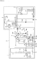
- FIG. 2 is a diagram showing the flow of refrigerant when a first embodiment of a water circulation system associated with a refrigerant cycle according to the present invention is operated in one-stage compression type
- FIG. 3 is a diagram showing the flow of refrigerant when a first embodiment of a water circulation system associated with a refrigerant cycle according to the present invention is operated in two-stage compression type
- FIG. 4 is a diagram showing the flow of refrigerant when a first embodiment of a water circulation system associated with a refrigerant cycle according to the present invention is operated in one-stage and two-stage mixed compression type.
- the water circulation system S associated with the refrigerant cycle can perform a heating operation in three operation states such as the one-stage compression operation, the two-stage compression operation, and the mixed operation.
- the one-stage compression operation means an operation state in which the water that flows in any one of the hot water supplying unit 4 and the cooling/heating unit 5 is heated by the first refrigerant.
- the two-stage compression operation means an operation state in which the water that flows in any one of the hot water supplying unit 4 and the cooling/heating unit 5 is heated by the second refrigerant.
- the mixed operation means an operation state in which the water that flows in any one of the hot water supplying unit 4 and the cooling/heating unit is heated by the first refrigerant and the second refrigerant at the same time.
- the water is heated by a single refrigerant cycle performed by the first refrigerant.
- the second refrigerant is heated by a first refrigerant cycle performed by the first refrigerant and the water is heated by a second refrigerant cycle performed by the second refrigerant.
- the mixed operation the water is heated by two refrigerant cycles performed by the first refrigerant and the second refrigerant at the same time.
- the refrigerant cycle is performed.
- the first flow switch 12 maintains a state to guide the refrigerant discharged from the first compressor 11 to the intermediate heat exchanger 25.
- the flow of the refrigerant is stopped. That is, the operation stop of the second compressor 21 is maintained.
- the water circulation unit the water discharged from the water pump 36 is introduced into any one of the hot water supplying unit 4 and the cooling/heating unit 5.
- the water passing through any one of the hot water supplying unit 4 and the cooling/heating unit 5 is introduced into the branch pipe 303.
- the second flow control unit 305 maintains a closed state to prevent the flow of the water to the water refrigerant heat exchanger 23.
- the first flow control unit 304 and the second flow control unit 305 maintain an opened state.
- the water introduced into the branch pipe 303 passes through the intermediate heat exchanger 25. While the water passes through the intermediate heat exchanger 25, the water is heated by exchange the heat with the first refrigerant. The water passing through the intermediate heat exchanger 25 is again introduced into the water pump 36 through the water collection tank 34.
- the flow of the first refrigerant is the same as the case where the water circulation system S associated with the refrigerant cycle operates in the one-stage compression type.
- the second refrigerant discharged from the second compressor 21 is introduced into the water refrigerant heat exchanger 23. While the second refrigerant introduced into the water refrigerant heat exchanger 23 passes through the water refrigerant het exchanger 23, the second refrigerant emits the heat to the water.
- the second refrigerant passing through the water refrigerant heat exchanger 23 is expanded while passing through the second expansion unit 24 and thereafter is introduced into the intermediate heat exchanger 25. While the second refrigerant passes through the intermediate heat exchanger 25, the second refrigerant absorbs the heat from the first refrigerant and thereafter, is again introduced into the second compressor 21.
- the second flow switch guides the second refrigerant discharged from the second compressor 21 to the water refrigerant heat exchanger 23 and guides the refrigerant passing through the intermediate heat exchanger 25 to the second compressor 21.
- the water discharged from the water pump 36 is introduced into any one of the hot water supplying unit 4 and the cooling/heating unit 5.
- the water passing through any one of the hot water supplying unit 4 and the cooling/heating unit 5 is introduced into the main pipe 302.
- the first flow control unit 304 maintains the closed state to prevent the flow of the water to the intermediate heat exchanger 25.
- the second flow control unit 306 maintains the opened state.
- the water introduced into the main pipe 302 passes through the water refrigerant heat exchanger 23. While the water passes through the water refrigerant heat exchanger 23, the water is heated by exchange the heat with the second refrigerant. The water passing through the water refrigerant heat exchanger 23 is again introduced into the water pump 36 through the water collection tank 34.
- the flows of the first refrigerant and the second refrigerant are the same as the case where the water circulation system S associated with the refrigerant cycle operates in the two-stage compression type.
- the water discharged from the water pump 36 is introduced into any one of the hot water supplying unit 4 and the cooling/heating unit 5.
- the water passing through any one of the hot water supplying unit 4 and the cooling/heating unit 5 is introduced into the main pipe 302 and the branch pipe 303 at the same time.
- both the first flow control unit 304 and the second flow control unit 306 maintain the opened state.
- the water introduced into the main pipe 302 and the water introduced into the branch pipe 303 pass through the water refrigerant heat exchanger 23 and the intermediate heat exchanger 25, respectively. While the water passes through the intermediate heat exchanger 25, the water is heated by exchanging the heat with the first refrigerant and while the water passes through the water refrigerant heat exchanger 23, the water is heated by exchanging the heat with the second refrigerant. That is, the water is heated by the first refrigerant and the second refrigerant at the same time.
- the water passing through the water refrigerant heat exchanger 23 and the intermediate heat exchanger 25 is again introduced into the water pump 36 through the water collection tank 34.
- the first refrigerant and the second refrigerant flow in reverse order in the first refrigerant circulation unit and the second refrigerant circulation unit in comparison with the case where the system operates in the heating mode.
- FIG. 5 is a diagram showing the shape of an intermediate heat exchanger in a first embodiment of a water circulation system associated with a refrigerant cycle according to the present invention.
- the intermediate heat exchanger 25 is a plate-type heat exchanger 25 that includes three flow passages adjacent to each other where the first refrigerant, the second refrigerant, and water flow independently.
- the plate-type heat exchanger 25 includes a plurality of plates 254, 255, and 256 that forms a plurality of flow passages 251, 252, and 253 where the first refrigerant, the second refrigerant, and water flow independently.
- One side of the plates 254, 255, and 256 is formed with an introduction portion 257 into which any one of the first refrigerant, the second refrigerant, and water is introduced and the other thereof is formed with a discharge portion 258 from which any one of the first refrigerant, the second refrigerant, and water is discharged.
- the introduction portion 257 and the discharger portion 258 communicate with the plurality of flow passages 251, 252, and 253.
- each of the plurality of flow passages 251, 252, and 253 communicates with the introduction portion 257 and the discharge portion 258 of any one of the first refrigerant, the second refrigerant, and water so that any one of the first refrigerant, the second refrigerant, and water can flow.
- the first refrigerant flows through any one flow passage 252 that is positioned between the remaining flow passages 251 and 253 among the plurality of flow passages 251, 252, and 253. More specifically, the second refrigerant flows through the first flow passage 251 of the plurality of flow passages 251, 252, and 254, the water flows through the third flow passage 253, and the first refrigerant flows through the second flow passage 252 that is positioned between the first flow passage 251 and the third flow passage 253.
- the heat exchange performance through the intermediate heat exchanger 25 can be maximized.
- the heat exchange of the first refrigerant and water is performed through the intermediate heat exchanger 25, in the two-stage compression operation, the heat exchanger of the second refrigerant and water is performed through the intermediate heat exchanger 25, and in the mixed operation, the heat exchange of the first refrigerant, the second refrigerant, and water is performed through the intermediate heat exchanger 25. Therefore, the first refrigerant and water that flow the intermediate heat exchanger 25 can perform the heat exchanger in the adjacent state to each other regardless of the operation state of the water circulation system (S) associated with the refrigerant cycle.
- FIG. 6 is a control configuration diagram of the first embodiment of the water circulation system associated with the refrigerant cycle according to the present invention
- FIG. 7 is a flowchart showing a control flow when the first embodiment of the water circulation system associated with the refrigerant cycle according to the present invention performs a heating operation
- FIG. 8 is a flowchart showing a control flow when the first embodiment of the water circulation system associated with the refrigerant cycle according to the present invention performs a defrosting operation.
- the water circulation system (S) associated with the refrigerant cycle includes an outdoor temperature sensor 72 that senses the temperature of outdoor air, a target temperature sensor 73 that senses the temperature of a target to be operated by the water circulation system (S) associated with the refrigerant cycle, and a control unit 75 that controls the first flow controller 304 and the second flow controller 306 based on the outdoor air temperature and the target temperature.
- the outdoor temperature sensor 72, the target temperature sensor 73, the first flow control unit 304, the second flow control unit 306, and the control unit 75 are electrically connected to each other so that they can transmit and receive signals to and from each other.
- the target to be operated by the water circulation system (S) associated with the refrigerant cycle means a target to be controlled for the cooling and heating and hot water supplying.
- the target to be operated may be an indoor temperature that means the temperature of indoor air, a discharge temperature that means a temperature of water discharged from the intermediator 2, an introduction temperature that means the temperature of water introduced into the intermediator 2, etc.
- the outdoor temperature that means the temperature of the outdoor air and the target temperature that means the target temperature to be operated are sensed (S11).
- the first flow control unit 304 When the outdoor temperature is a first reference temperature or more and the target temperature is below a second reference temperature (S12), the first flow control unit 304 is opened and the second flow control unit 306 is closed (S13). However, when the outdoor temperature is a first reference temperature or more and the target temperature is below a second reference temperature (S12), the first flow control unit 304 is opened and the second flow control unit 306 is closed (S14).
- the case where the first flow control unit 304 is opened and the second flow control unit 306 is closed corresponds to the one-stage compression operation and the case where the first flow control unit 304 is closed and the second flow control unit 306 is opened corresponds to the two-stage compression operation. Therefore, the case where the outdoor temperature is the first reference temperature or more and the target temperature is below the second reference temperature may be referred to as the one-stage compression condition and the case other than the case where the outdoor temperature is the first reference temperature or more and the target temperature is below the second reference temperature may be referred to as the two-stage compression condition.
- the first reference temperature and the second reference temperature mean the outdoor temperature and the target temperature corresponding to the operation conditions where the efficiency of the water circulation system (S) associated with the refrigerant cycle in the case of the one-stage compression operation and the efficiency of the water circulation system (S) associated with the refrigerant cycle of the two-stage compression operation are identical.
- the efficiency of the case of the one-stage compression operation is higher than the efficiency of the case of the two-stage compression operation.
- the efficiency of the case of the two-stage compression operation is higher than the efficiency of the case of the one-stage compression operation. Therefore, while the outdoor temperature and the target temperature are changed, there may be the outdoor temperature and the target temperature where the efficiency of the case of the two-stage compression operation is the same level of the efficiency of the case of the one-stage compression operation. Therefore, according to the control flow, the operation state of the water circulation system (S) associated with the refrigerant cycle is varied in the direction where the operation efficiency is higher according to the outdoor temperature and the target temperature.
- the operation efficiency can be maximized.
- the water circulation system (S) associated with the refrigerant cycle when the efficiency of the one-stage compression is operated is higher the efficiency of the case of the two-stage compression operation based on the first reference temperature and the second reference temperature as a reference, the water circulation system (S) associated with the refrigerant cycle is operated in the one-stage compression type and when the efficiency of the two-stage compression operation is higher than the efficiency of the one-stage compression operation, the water circulation system (S) associated with the refrigerant cycle is operated in the two-stage compression type. Therefore, the water circulation system (S) associated with the refrigerant cycle may be operated in the direction where the operation efficiency can be maximized according to the outdoor temperature and the target temperature.
- the water circulation system associated with the refrigerant cycle is first operated in a mode set by the user's selection (S21).
- the defrosting operation to be described below is high likely to be need in the environment where the external temperature of the heat exchanger serving as an evaporator is below zero temperature, that is, the winter where the heating operation is mainly performed. Therefore, the water circulation system associated with the refrigerant cycle that performs the defrosting operation during the heating operation as described above will be described.
- the defrosting operation condition is satisfied (S22). Whether the defrosting operation condition is operated may be determined by comparing the pipe outlet temperature of the outdoor heat exchanger 13 with the outdoor temperature. However, in the present embodiment, the determination on whether the defrosting operation condition is satisfied may be performed in various methods and therefore, it is to be noted that the present embodiment can use a method for determining whether the defrosting operation is satisfied, without limitation.
- the first refrigerant circulation unit When the defrosting operation condition is satisfied, the first refrigerant circulation unit is operated in a defrosting mode and the second refrigerant circulation unit maintains the operation mode (heating mode) (S23).
- the intermediate heat exchanger 25 serves as the evaporator in each refrigerant circulation units 1 and 2 and the outdoor heat exchanger 25 serves as a condenser. Therefore, while the first refrigerant circulation unit is operated in the defrosting mode, the defrosting of the outdoor heat exchanger 13 is performed by the high-temperature refrigerant that flows to the outdoor heat exchanger 13.
- the first flow control unit 304 and the third flow control unit 305 are closed (S24).
- the flow of water stops in the branch pipe 303 and the hot water is heat exchanged with the first refrigerant inside the branch pipe 303.
- the first refrigerant heat exchanged with the hot water and the second refrigerant is heat exchanged, such that the temperature of each refrigerant is increased, thereby making it possible to minimize the reduction of the evaporation pressure of each refrigerant circulation unit.
- the closed first flow control unit 304 and third control unit 305 are opened (S26).
- the first refrigerant circulation unit is operated in a previous mode (S27). That is, the first refrigerant circulation unit is operated in a heating mode.
- the second refrigerant circulation unit is continuously operated in the heating mode, such that the indoor heating or the hot water supplying can be performed.
- the hot water of the branch pipe 303 is heat exchanged with the first refrigerant that flows to the intermediate heat exchanger 25 to increase the temperature of the first refrigerant, such that the evaporation pressure of each refrigerant circulation unit is minimized, thereby making it possible to minimize the performance degradation of each refrigerant circulation unit.
- the second embodiment is different from the first embodiment in that the intermediate heat exchanger is formed in a triple-pipe, the mixed operation is performed during the reference time in the case of the two-stage compression condition, and the first flow control unit 304 and the third flow control unit 305 are opened during the defrosting operation.
- FIG. 9 is a diagram showing a shape of the intermediate heat exchanger of the second embodiment of the water circulation system associated with the refrigerant cycle according to the present invention
- FIG. 10 is a flowchart showing a control flow when the second embodiment of the water circulation system associated with the refrigerant cycle according to the present invention performs a heating operation
- FIG. 11 is a flowchart showing a control flow when the second embodiment of the water circulation system associated with the refrigerant cycle according to the present invention performs a defrosting operation.
- the intermediate heat exchanger 85 is a triple-pipe shape in which three independent flow passages are formed by three pipes having a concentric axis and different diameters.
- the intermediate heat exchanger 85 includes a first flow passage 851 positioned at the innermost side, a second flow passage 852 positioned outside of the first flow passage 851, and a third flow passage 853 positioned outside of the second flow passage 852.
- the first flow passage 851 is in communication with a second refrigerant pipe 26 through which second refrigerant flows
- the second flow passage 852 is in communication with a first refrigerant pipe 15 through which first refrigerant flows
- the third flow passage 853 is in communication with a water pipe 303 through which water flows. That is, the second refrigerant flows through the first flow passage 851, the first refrigerant flows through the second flow passage 852, and the water flows through the third flow passage 853.
- the intermediate heat exchanger 85 includes a plurality of heat exchanging units 86 and 87 that are removably connected with each other.
- the heat exchanging units 86 and 87 each include three flow passages 851, 852, and 853.
- Each of the heat exchange units 86 and 87 is connected to the first refrigerant pipe 15, the second refrigerant pipe 26, and the water pipe 303.
- a plurality of introduction portions 881, 883, and 885 and refrigerant discharge portions 882, 884, and 886 that are selectively connected to each of the plurality of heat exchanging units 86 and 87 are provided in the first refrigerant pipe 15, the second refrigerant pipe 26, and the water pipe 303.
- the plurality of introduction portions 881, 883, and 885 and refrigerant discharge portions 882, 884, and 886 include a first refrigerant introduction portion 881 and a first refrigerant discharge portion 882 for introducing and discharging the first refrigerant, a second refrigerant introduction portion 883 and a second refrigerant discharge portion 884 for introducing and discharging the second refrigerant , and a water introduction portion 885 and a water discharge portion 886 for introducing and discharging the water.
- each of the plurality of introduction portion 881, 883, and 885 and discharge portions 882, 884, and 886 includes a plurality of flow preventing portions 857 for selectively shielding the plurality of introduction portion 881, 883, and 885 and discharge portions 882, 884, and 886.
- the plurality of flow preventing portions 857 selectively prevents the flow of at least one of the first refrigerant, the second refrigerant, and the water through the plurality of introduction portion 881, 883, and 885 and discharge portions 882, 884, and 886.
- the heat exchange capacity of the intermediate heat exchanger 85 may be varied depending on the number of the heat exchanging units 86 and 87 connected to the first refrigerant pipe 15, the second refrigerant pipe 26, and the water pipe 303. Further, as the flow of the refrigerant to the plurality of heat exchanging units 86 and 87 is selectively prevented by the plurality of flow preventing portions 857, the heat exchange capacity of the intermediate heat exchanger 85 may be varied.
- the heat exchanging units 86 and 87 are selectively and removably connected to the introduction portions 881, 883, and 885 and the discharge portions 882, 884, and 886, the heat exchanging unit 86 and 87 may be connected to the introduction portions 881, 883, and 885 and the discharge portions 882, 884, and 886 by changing the number of connected portions as necessary.
- the number of the heat exchanging units 86 and 87 substantially used for exchanging the heat may be varied.
- the entire heat exchanging capacity of the intermediate heat exchanger 85 may be varied.
- the entire heat exchanging capacity of the intermediate heat exchanger 85 may be varied.
- the type in which the first refrigerant, the second refrigerant, and the water flows through three flow passages 851, 852, and 853 has various numbers of cases. That is, the first refrigerant flows through any one of three flow passages 851, 852, and 853, the second refrigerant flows through another of three flow passages 851, 852, and 853, and the water flows through the other one of three flow passages 851, 852, and 853. Accordingly, the first refrigerant, the second refrigerant, and the water may flow through three flow passages 851, 852, and 853 in six types.
- the flow directions of fluids that flow through adjacent flow passages among the fluids that flow through three flow passages 851, 852, and 853 are opposite to each other.
- the fluids include the first refrigerant, the second refrigerant, and the water. That is, two fluids that flow adjacent to each other among the first refrigerant, the second refrigerant, and the water flow opposite to each other in the intermediate heat exchanger 85. Accordingly, the heat exchange efficiency of the intermediate heat exchanger 85 can further be improved.
- the mixed operation is performed during the reference time in the case corresponding to the two-stage compression condition.
- the outdoor temperature and the target temperature are sensed (S31).
- the first flow control unit 304 is opened and the second flow control unit 306 is closed, such that the one-stage compression operation starts (S33).
- both the first flow control unit 304 and the second flow control unit 306 are opened, such that the mixed operation starts (S34).
- the outdoor temperature and the target temperature are sensed (S36).
- the first flow control unit 304 is closed, such that the two-stage compression operation starts (S38).
- the outdoor temperature and the target temperature are sensed again (S31).
- the reference time means the time required from the time when the first flow control unit 304 and the second flow control unit 306 are switched to the time when the outdoor temperature and the target temperature are stabilized.
- the efficiency of the water circulation system (S) associated with the refrigerant cycle can be optionally maintained according to the change in the outdoor temperature and the target temperature.
- the efficiency of the mixed operation may be higher than that of the two-stage compression operation.
- the efficiency of the mixed operation may be higher than that of the two-stage compression.
- the mixed operation is primarily performed during the reference time and despite of the mixed operation, when they does not enter the one-stage compression condition, the two-stage compression operation is finally performed. Therefore, the efficiency of the water circulation system (S) associated with the refrigerant cycle can be optionally maintained according to the outdoor temperature and the target temperature.
- the water circulation system associated with the refrigerant cycle is first operated in a mode set by the user's selection (S41).
- S41 the case where the present embodiment performs the defrosting operation during the heating operation will be described below.
- the first flow control unit 304 and the third flow control unit 305 of the branch pipe 303 maintain the closed state while each of the refrigerant circulation units 1 and 2 performs the heating operation. Further, the second flow control unit 306 maintains the opened state. Therefore, the water passing through the water circulation unit is heat exchanged with the second refrigerant while passing through the water refrigerant heat exchanger 23.
- the temperature of water flowing to the water pipe 61 is continuously increased.
- the temperature of water flowing to the main pipe 302 adjacent to the water refrigerant heat exchanger 23 is continuously increased.
- the first flow control unit 304 and the third flow control unit 305 are opened (S14).
- the first flow control unit 304 and the third flow control unit 305 are opened, at least a part of the hot water flowing to the water circulation unit is heat exchanged with the first refrigerant while flowing to the intermediate heat exchanger 25.
- the first refrigerant heat exchanged with the hot water and the second refrigerant is heat exchanged, such that the temperature of each refrigerant is increased, thereby making it possible to minimize the reduction of the evaporation pressure of each refrigerant circulation unit.
- the defrosting mode it is determined whether the defrosting is ended (S45). If it is determined whether the defrosting is ended, the closed first flow control unit 304 and third control unit 305 are closed (S46) . The first refrigerant circulation unit is operated in a previous mode (S47) . That is, the first refrigerant circulation unit will be operated in the heating mode.
- the first refrigerant circulation unit When the first refrigerant circulation unit is operated in the defrosting mode while each of the refrigerant circulation units 1 and 2 is operated in the heating mode, if the first flow control unit 304 and the third flow control unit 305 are in the closed state, the first flow control unit 204 and the third flow control unit 305 are opened and if the defrosting is ended, the first flow control unit 304 and the third flow control unit 305 can be closed. On the other hand, if the first flow control unit 304 and the third flow control unit 305 are in the opened state, the first flow control unit 304 and the third flow control unit 305 may be maintained in the opened state.
- the fourth embodiment is different from the first embodiment in that the flowing amount of water to the intermediate heat exchanger and the water refrigerant heat exchanger is controlled according to the outdoor temperature and the target temperature and when the defrosting operation is performed, it is opposite to the case of the heating operation in terms of the refrigerant flowing of the first refrigerant circulation unit and the second circulation unit.
- FIG. 12 is a flowchart showing a control flow when a third embodiment of a water circulation system associated with a refrigerant cycle according to the present invention performs a heating operation
- FIG. 13 is a flowchart showing a mixed operation process based on an outdoor temperature in the third embodiment of the water circulation system associated with the refrigerant cycle according to the present invention.
- FIG. 14 is a flowchart showing a mixed operation process based on a target temperature in the third embodiment of the water circulation system associated with the refrigerant cycle according to the present invention
- FIG. 15 is a flowchart showing a control flow when the third embodiment of the water circulation system associated with the refrigerant cycle according to the present invention performs a defrosting operation.
- the flowing amount of water to the intermediate heat exchanger 25 and the water refrigerant heat exchanger 23 is controlled according to the outdoor temperature and the target temperature.
- the outdoor temperature and the target temperature are sensed (S51).
- the first flow control unit 304 is opened and the second flow control unit 306 is closed, such that the one-stage compression operation starts (S53).
- the outdoor temperature and the target temperature corresponds to the one-stage compression condition (S52)
- the first flow control unit 304 is closed and the second flow control unit 306 is opened (S55) .
- the state where the first flow control unit 304 is closed and the second flow control unit 306 is opened means the two-stage compression operation. Therefore, the case where the outdoor temperature is below the first reference temperature and the target temperature is the second reference temperature or more may be referred to the two-stage compression condition.
- the outdoor temperature and the target temperature do not correspond to the two-stage compression condition (S54), it determines whether the outdoor temperature is below the first reference temperature (S56) and the target temperature is the second reference temperature or more (S58).
- the case where the outdoor temperature and the target temperature do not correspond to the two-stage compression condition (S54) and the outdoor temperature is below the first reference temperature (S56) or the target temperature is the second reference temperature or more (S58) may be referred to the mixed condition.
- the mixed operation includes the outdoor temperature reference mixed operation and the target temperature reference mixed operation.
- the outdoor temperature reference mixed condition the case where the outdoor temperature and the target temperature do not correspond to the two-stage compression condition and the outdoor temperature is below the first reference temperature
- the outdoor temperature reference mixed condition the case where the outdoor temperature and the target temperature do not correspond to the two-stage compression condition and the target temperature is the second reference temperature or more
- the target temperature reference mixed condition When the outdoor temperature and the target temperature corresponds to the outdoor temperature reference mixed condition (S56), the outdoor temperature reference mixed operation is performed (S57) and when they corresponds to the target temperature reference mixed condition (S58), the target temperature reference mixed operation is performed (S59).
- the outdoor temperature reference mixed operation determines whether the outdoor temperature is below the third reference temperature (S571).
- the two-stage compression operation is performed (S572).
- the opening degrees of the first flow control unit 304 and the second flow control unit 306 are controlled so that the ratio of the difference of the first reference temperature and the outdoor temperature with respect to the difference of the first reference temperature and the third reference temperature is the same as the ratio of the opening degree of the second flow control unit 306 with respect to the opening degree of the first flow control unit 304 (S573).
- the third reference temperature means the outdoor temperature that makes the efficiency of the mixed operation and the efficiency of the two-stage compression operation same.
- the efficiency of the mixed operation is higher than that of the two-stage compression operation.
- the efficiency of the two-stage compression operation is higher than that of the mixed operation.
- the third reference temperature corresponds to a temperature value smaller than the first reference temperature.
- the target temperature reference mixed operation when the target temperature reference mixed operation is performed, it determines whether the target temperature corresponds to a fourth reference temperature or more (S591). When the outdoor temperature corresponds to the fourth reference temperature or more, the two-stage compression operation is performed (S592).
- the opening degrees of the first flow control unit 304 and the second flow control unit 306 are controlled so that the ratio of the difference of the first reference temperature and the outdoor temperature with respect to the difference of the fourth reference temperature and the second reference temperature is the same as the ratio of the opening degree of the second flow control unit 306 with respect to the opening degree of the second flow control unit 306 (S593).
- the fourth reference temperature means the target temperature that makes the efficiency of the mixed operation and the efficiency of the two-stage compression operation same.
- the target temperature when the target temperature is higher than the fourth reference temperature, the efficiency of the two-stage compression operation is higher than that of the mixed operation.
- the target temperature when the target temperature is lower than the fourth reference temperature, the efficiency of the mixed operation is higher than that of the two-stage compression operation.
- the fourth reference temperature corresponds to a temperature value higher than the second reference temperature.
- the operation efficiency of the water circulation system (S) associated with the refrigerant cycle can be more optimized according to the change in the outdoor temperature and the target temperature.
- the opening degrees of the first flow control unit 304 and the second flow control unit 306 are varied according to any one of the difference of the outdoor temperature and the third reference temperature and the difference of the target temperature and the fourth reference temperature.
- the opening degree of the first flow control unit 304 is relatively increased compared to the opening degree of the second flow control unit 306.
- the water circulation system (S) associated with the refrigerant cycle is operated in a state close to the one-stage compression operation.
- the opening degree of the second flow control unit 306 is relatively increased compared to the opening degree of the first flow control unit 304.
- the water circulation system (S) associated with the refrigerant cycle is operated in a state close to the two-stage compression operation.
- the opening degree of the first flow control unit 304 is relatively increased compared to the opening degree of the second flow control unit 306.
- the water circulation system (S) associated with the refrigerant cycle is operated in a state close to the one-stage compression operation.
- the opening degree of the second flow control unit 306 is relatively increased compared to the opening degree of the first flow control unit 304.
- the water circulation system (S) associated with the refrigerant cycle is operated in a state close to the two-stage compression operation.
- the flowing amount of water to the intermediate heat exchanger 25 and the flowing amount of water to the water refrigerant heat exchanger 23 are varied to be in inverse proportion to each other.
- the water circulation system (S) associated with the refrigerant cycle can be optionally operated according to the outdoor temperature and the target temperature.
- the water circulation system (S) associated with the refrigerant cycle is first operated in a mode set by the user's selection (S61). The case where the defrosting operation is performed during the heating operation will be described below.
- the case where the first refrigerant circulation unit is operated in the defrosting mode means the case where the first refrigerant circulation unit is operated in the cooling mode.
- the case where the second refrigerant circulation unit is operated in the defrosting mode means the following two cases.
- the first case means the case where the operation of the second refrigerant circulation unit stops and the second case means the case where the second compressor 21 is operated at a lower frequency than the operation frequency of the second compressor in the previous mode while the second refrigerant circulation unit is basically operated in the heating mode.
- the second refrigerant circulation unit when operated in the heating mode, if the first flow control unit 304 and the third flow control unit 305 are opened, the first flow control unit 304 and the third flow control unit 305 are closed. As described in the first embodiment, when the first flow control unit 304 and the third flow control unit 305 are closed, the hot water inside the branch pipe 303 and the first refrigerant are heat exchanged with each other.
- the first flow control unit 304 and the third flow control unit 305 may be the closed state or the opened stated and the opening or closing of the first flow control unit 304 and the third flow control unit 305 can be controlled in the method described in the previous embodiments when the first refrigerant circulation units 1 and 2 are operated in the defrosting mode.
- each refrigerant circulation unit is operated in the defrosting mode, it is determined whether the defrosting is ended (S64). When the defrosting is ended, each refrigerant circulation unit is operated in the previous mode (S65). That is, each refrigerant circulation unit will be operated in the heating mode.
- the fifth embodiment is different from the first embodiment in that the first flow control unit and the second flow control unit are controlled according to the operation or not of the second compressor and the flowing amount of water flowing to the water circulation unit is reduced during the defrosting operation.
- FIG. 16 is a control configuration diagram of a fourth embodiment of a water circulation system associated with a refrigerant cycle according to the present invention
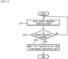
- FIG. 17 is a flowchart showing a control flow when the fourth embodiment of the water circulation system associated with the refrigerant cycle according to the present invention performs a heating operation
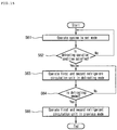
- FIG. 18 is a flowchart showing a control flow when the fourth embodiment of the water circulation system associated with the refrigerant cycle according to the present invention performs a defrosting operation.
- the first flow control unit 304 and the second flow control unit 306 are controlled according to the operation or not of the second compressor 21.
- the present embodiment includes a second compressor operation sensing unit 91 that senses the operation or not of the second compressor 21 and transmits it to the control unit 95.
- the operation of the second operation 21 is sensed (S71).
- a rotation sensor that senses the rotation or not of the compressor or a method for sensing the current or voltage supplied to the compressor, etc.
- the operation of the second compressor 21 stops, there may be various situations such as the malfunction or fault of the second compressor 21, etc. Since the flowing of the second refrigerant stops in the state where the second compressor 21 stops, the water introduced into the water refrigerant heat exchanger 23 passes therethrough without the change in state. In this case, the water continuously flows to the water refrigerant heat exchanger 23, which may have a bad effect on the operation for the indoor cooling and heating and the hot water supplying.
- the water circulation system (S) associated with the refrigerant cycle is first operated in a mode set by the user's selection (S81).
- the intermediate heat exchanger 25 serves as the evaporator for each refrigerant circulation units 1 and 2.
- the intermediated heat exchanger serves as the evaporator for each refrigerant circulation unit, such that the evaporation pressure of each refrigerant circulation unit becomes small, thereby makes the condensing temperature of the second heat exchanger 23 low.
- the condensing temperature of the second heat exchanger 23 is low, the temperature of water stored in the water collection tank 34 is low.
- the temperature of water stored in the water collection tank 34 is low, the temperature of water flowing to the cooling and heating pipe 63 of the cooling and heating unit 5 is low, such that the indoor temperature may be low.
- the operation of the water pump 36 is changed so that the amount of water flowing to the water circulation unit is more reduced than when the first refrigerant circulation unit is operated in the heating mode (S84).
- the amount of water flowing to the cooling and heating pipe 63 of the cooling and heating unit 5 is reduced, thereby making it possible to minimize the reduction of the indoor temperature.
- the water pump 36 is operated in the previous state, such that the flowing amount of the cooling and heating pipe 63 is returned to the previous state (S86).
- the first refrigerant circulation unit is operated in the previous mode (S87).
Landscapes
- Engineering & Computer Science (AREA)
- Physics & Mathematics (AREA)
- Mechanical Engineering (AREA)
- Thermal Sciences (AREA)
- General Engineering & Computer Science (AREA)
- Steam Or Hot-Water Central Heating Systems (AREA)
- Heat-Pump Type And Storage Water Heaters (AREA)
- Other Air-Conditioning Systems (AREA)
- Compression-Type Refrigeration Machines With Reversible Cycles (AREA)
- Sorption Type Refrigeration Machines (AREA)
Description
- The present invention relates to a water circulation system associated with a refrigerant cycle. Embodiments perform a hot water supplying function and cooling and heating functions in association with the refrigerant cycle.
- In the related art, indoor cooling and heating are performed by an air conditioner using the refrigerant cycle and supplying hot water is performed by a boiler with an additional heating source.
- More specifically, the air conditioner includes an outdoor unit installed in an outdoor area and an indoor unit installed in an indoor area. The outdoor unit includes a compressor compressing refrigerant, an outdoor heat exchanger for exchanging heat of outdoor air with the refrigerant, and a decompressing device and the indoor unit includes an indoor heat exchanger for exchanging heat of indoor air with the refrigerant. At this time, any one of the outdoor heat exchanger and the indoor heat exchanger serves as a condenser and the other one serves as an evaporator and the compressor, the outdoor heat exchanger, the decompressing device, and the indoor heat exchanger perform a refrigerant cycle.
- In addition, the boiler generates heat by using oil, gas, or electricity and heats water to supply hot water or perform floor heating.
-
CN 2570706 describes a heating device that transforms groundwater low-grade heat into high-grade heat using low and high temperature water circulation cycles. - The present invention provides a water circulation system associated with a refrigerant cycle that can selectively heat exchange water for cooling and heating and hot water supplying with at least one of a first refrigerant and a second refrigerant, and in particular a water circulation system associated with the a refrigerant cycle according to the appended claims.
- The present invention can improve the operation efficiency of the water circulation system associated with the refrigerant cycle.
-
-
FIG. 1 is a configuration diagram of a first embodiment of a water circulation system associated with a refrigerant cycle according to the present invention; -
FIG. 2 is a diagram showing the flow of refrigerant when a first embodiment of a water circulation system associated with a refrigerant cycle according to the present invention is operated in one-stage compression type; -
FIG. 3 is a diagram showing the flow of refrigerant when a first embodiment of a water circulation system associated with a refrigerant cycle according to the present invention is operated in two-stage compression type; -
FIG. 4 is a diagram showing the flow of refrigerant when a first embodiment of a water circulation system associated with a refrigerant cycle according to the present invention is operated in one-stage and two-stage mixed compression type; -
FIG. 5 is a diagram showing the shape of an intermediate heat exchanger in a first embodiment of a water circulation system associated with a refrigerant cycle according to the present invention; -
FIG. 6 is a control configuration diagram of a first embodiment of a water circulation system associated with a refrigerant cycle according to the present invention; -
FIG. 7 is a flowchart showing a control flow when the first embodiment of the water circulation system associated with the refrigerant cycle according to the present invention performs a heating operation; -
FIG. 8 is a flowchart showing a control flow when the first embodiment of the water circulation system associated with the refrigerant cycle according to the present invention performs a defrosting operation; -
FIG. 9 is a diagram showing the shape of an intermediate heat exchanger in a second embodiment of a water circulation system associated with a refrigerant cycle according to the present invention; -
FIG. 10 is a flowchart showing a control flow when the second embodiment of the water circulation system associated with the refrigerant cycle according to the present invention performs a heating operation; -
FIG. 11 is a flowchart showing a control flow when the second embodiment of the water circulation system associated with the refrigerant cycle according to the present invention performs a defrosting operation; -
FIG. 12 is a flowchart showing a control flow when a third embodiment of a water circulation system associated with a refrigerant cycle according to the present invention performs a heating operation; -
FIG. 13 is a flowchart showing a mixed operation process based on an outdoor temperature in the third embodiment of the water circulation system associated with the refrigerant cycle according to the present invention; -
FIG. 14 is a flowchart showing a mixed operation process based on a target temperature in the third embodiment of the water circulation system associated with the refrigerant cycle according to the present invention; -
FIG. 15 is a flowchart showing a control flow when the third embodiment of the water circulation system associated with the refrigerant cycle according to the present invention performs a defrosting operation; -
FIG. 16 is a control configuration diagram of a fourth embodiment of a water circulation system associated with a refrigerant cycle according to the present invention; -
FIG. 17 is a flowchart showing a control flow when the fourth embodiment of the water circulation system associated with the refrigerant cycle according to the present invention performs a heating operation; and -
FIG. 18 is a flowchart showing a control flow when the fourth embodiment of the water circulation system associated with the refrigerant cycle according to the present invention performs a defrosting operation. - Reference will now be made in detail to the embodiments of the present disclosure, examples of which are illustrated in the accompanying drawings.
- In the following detailed description of the preferred embodiments, reference is made to the accompanying drawings that form a part hereof, and in which is shown by way of illustration specific preferred embodiments in which the invention may be practiced. These embodiments are described in sufficient detail to enable those skilled in the art to practice the invention, and it is understood that other embodiments may be utilized and that logical structural, mechanical, electrical, and chemical changes may be made without departing from the spirit or scope of the invention. To avoid detail not necessary to enable those skilled in the art to practice the invention, the description may omit certain information known to those skilled in the art. The following detailed description is, therefore, not to be taken in a limiting sense, and the scope of the present invention is defined only by the appended claims.
-
FIG. 1 is a configuration diagram of a first embodiment of a water circulation system associated with a refrigerant cycle according to the present invention. - Referring to
FIG. 1 , the water circulation system S associated with the refrigerant cycle includes a first refrigerant circulation unit where first refrigerant exchanging heat with outdoor air flows to perform the refrigerant cycle, a second refrigerant circulation unit where second refrigerant exchanging heat with the first refrigerant flows to perform the refrigerant cycle, and a water circulation unit where water for at least one of indoor heating/cooling and hot water supplying. At this time, the refrigerant cycle means transmitting the heat by repetitively performing compression, condensation, expansion, and evaporation processes. - In addition, the water circulation system S associated with the refrigerant cycle includes an outdoor unit 1 where an
outdoor heat exchanger 13 exchanging the first refrigerant and the outdoor air with each other is installed and anintermediator 2 that intermediates the outdoor 1 with the water circulation unit and includes a waterrefrigerant heat exchanger 23 exchanging heat between the second refrigerant and water. - Specifically, the first refrigerant circulation unit includes the
outdoor heat exchanger 13, a first compressor 11 compressing the first refrigerant, afirst expansion unit 14 expanding the first refrigerant, afirst flow switch 12 switching a flow direction of the first refrigerant, anintermediate heat exchanger 25 exchanging heat between the first refrigerant and the second refrigerant, and afirst refrigerant pipe 15. That is, the first refrigerant performs the refrigerant cycle while sequentially circulating any one of the first compressor 11, theoutdoor heat exchanger 13, and theintermediate heat exchanger 25 and the other one of thefirst expansion unit 14, theoutdoor heat exchanger 13, and the intermediate heat exchanger. Further, by thefirst flow switch 12, the flow direction of the first refrigerant may be switched into a direction in which the first refrigerant is introduced into theoutdoor heat exchanger 13 from theintermediate heat exchanger 25 through thefirst expansion unit 14 or a reverse direction. - In addition, the second refrigerant circulation unit includes the
intermediate heat exchanger 25, asecond compressor 21 compressing the second refrigerant, asecond expansion unit 24 expanding the second refrigerant, asecond flow switch 22 switching a flow direction of the second refrigerant, the waterrefrigerant heat exchanger 23, and asecond refrigerant pipe 26. That is, the second refrigerant performs the refrigerant cycle while sequentially circulating any one of thesecond compressor 21, theintermediate heat exchanger 25, and the waterrefrigerant heat exchanger 23 and the other one of thesecond expansion unit 24, theintermediate heat exchanger 25, and the waterrefrigerant heat exchanger 23. Further, by thesecond flow switch 22, the flow direction of the second refrigerant may be switched into a direction in which the second refrigerant is introduced into theintermediate heat exchanger 25 from the waterrefrigerant heat exchanger 23 through thesecond expansion unit 24 or a reverse direction. - At this time, the intermediate heat exchanger 25 through which the first referent, second refrigerant, and water pass at the same time is included in the first refrigerant circulation unit or included in the second refrigerant circulation unit. In addition, in the
intermediate heat exchanger 25, threeflow passages intermediate heat exchanger 25, the first refrigerant, second refrigerant, and water exchange heat with each other at the same time. That is, theintermediate heat exchanger 25 serves as the water refrigerant heat exchanger where the heat is exchanged between the water and the water in a functional sense. - In another aspect, the
intermediate heat exchanger 25 may serve as a first water refrigerant heat exchanger where the heat is exchanged between the first refrigerant and the water and the waterrefrigerant heat exchanger 23 may serve as a second water refrigerant heat exchanger where the heat is exchanged between the second refrigerant and the water. - Meanwhile, the
outdoor heat exchanger 13, the first compressor 11, thefirst expansion unit 14, and thefirst flow switch 12 are installed in the outdoor unit 1. In the case where the outdoor unit 1 is operated in a cooling mode, theoutdoor heat exchanger 13 serves as the condenser and serves as the evaporator in the case where the outdoor unit 1 is operated in a heating mode. - In addition, the
intermediate heat exchanger 25, the waterrefrigerant heat exchanger 23, thesecond compressor 21, and thesecond flow switch 22 are installed in theintermediator 2. Moreover, in theintermediator 2, the waterrefrigerant heat exchanger 23, aflow switch 32 that is mounted on awater pipe 61 extending to the outlet of the waterrefrigerant heat exchanger 23 and senses the flow of the water, anexpansion tank 33 branched from any point separated from theflow switch 32 in the flow direction of the water, awater collection tank 34 into which the end of thewater pipe 61 extending from the outlet of the waterrefrigerant heat exchanger 23 is inserted and which anauxiliary heat 35 is provided, and awater pump 36 provided at any point of thewater pipe 61 of the outlet side of thewater collection tank 34. - More specifically, the water
refrigerant heat exchanger 23 may adopt, for example, a plate-type heat exchanger as a device where the heat is exchanged between refrigerant that flows on a closed circuit of the refrigerant cycle and water that flows on thewater pipe 61. At least twoflow passages refrigerant heat exchanger 23. - Further, when the volume of water heated while passing through the water
refrigerant heat exchanger 23 is expanded at an appropriate level or more, theexpansion tank 33 performs an absorption function to absorb the expansion. - Further, the
water collection tank 34 is a container where the water passing through the waterrefrigerant heat exchanger 23 is collected. In addition, theauxiliary heat 35 is mounted in thewater collection tank 34, such that theauxiliary heat 35 is selected operated in the case where a heat quantity transferred through the waterrefrigerant heat exchanger 23 does not reach a required heat quality like a case where a defrosting operation is performed. - In addition, an
air vent 343 is formed on the top of thewater collection tank 34 to discharge air of an overheat state that exists in thewater collection tank 34. Moreover, apressure gauge 341 and arelief valve 342 are provide at one portion of thewater collection tank 34, such that the internal pressure of thewater collection tank 34 may appropriately be controlled. For example, when the internal water pressure of thewater collection tank 34 displayed through thepressure gauge 341 is excessively high, therelief valve 342 is opened to appropriately control the internal pressure of the tank. - Further, the
water pump 36 pumps water discharged through thewater pip 61 extending from the outlet of thewater collection tank 34 to supply it to a hot water supplying unit 4 and a cooling/heating unit 5. - Meanwhile, the water circulation unit includes the hot water supplying unit 4 where water for supplying hot water, that is, hot water supplying flows and the cooling/
heating unit 5 where water for indoor cooling and heating flows. - More specifically, the hot water supplying unit 4 is a part heating and supplying water required for an operation such as user's washing or dish-washing. Specifically, a three-
way valve 71 controlling the flow of the water is provided at any point separated from thewater pump 36 in the flow direction of the water. The three-way valve 71 is a direction change valve that allows the water pumped by thewater pump 36 to flow to the hot water supplying unit 4 or the cooling/heating unit 5. Accordingly, each of a hotwater supplying pipe 62 extending to the hot water supplying unit 4 and the cooling/heating pipe 63 extending to the cooling/heating unit 5 are connected to the outlet of the three-way valve 71. In addition, the water pumped by thewater pump 36 selectively flows to any one of the hotwater supplying pipe 62 or the cooling/heating pipe 63 by the control of the three-way valve 71. - A hot
water supplying tank 41 that stores water supplied from the outside and heats the stored water and anauxiliary heat 42 that is provided in the hotwater supplying tank 41 are included in the hot water supplying unit 4. In addition, awater introduction portion 411 for introducing cooling water and awater discharge portion 412 for discharging heated water are provided on one side of the hot water supplying unit. - Specifically, a part of the hot
water supplying pipe 62 extending from the three-way valve 71 is inputted into the hotwater supplying tank 41 and heats the water stored in the hotwater supplying tank 41. That is, heat is transmitted from high-temperature water that flows along the inside of the hotwater supplying pipe 62 to the water stored in the hotwater supplying tank 41. In addition, in a predetermined case, theauxiliary heat 35 and the auxiliary heat source operate to further supply additional heat. For example, like a case where the user needs a lot of water to take a bath, they may operate when the water needs to be heated within a short time. According to the embodiment, a water discharge device such as a shower or a home appliance device such as a humidifier may be connected to thewater discharge unit 412. - Meanwhile, the cooling/
heating unit 5 includes a floor cooling/heating unit 51 formed by burying a part of the cooling/heating pipe 63 in an indoor floor and an air cooling/heating unit 52 that is branched from any one point of the cooling/heating pipe 63 and in parallel, connected with the floor cooling/heating unit 51. - Specifically, the floor cooling/
heating unit 51 may be buried in the indoor floor in the form of a meander line as shown in the figure. Further, the air cooling/heating unit 52 may be a fan coil unit or a radiator, etc. Further, in the air cooling/heating unit 52, a part of the air cooling/heating pipe 54 branched from the cooling/heating pipe 63 is provided as a heat exchange means. Moreover, a flowpassage switching valve 56 such as the three-way valve 71 is installed at a point where the air cooling/heating pipe 54 is branched and refrigerant that flows on the cooling/heating pipe 63 flows by being divided into the floor cooling/heating unit 51 and the air cooling/heating unit 52 or flows to only any one of the floor cooling/heating unit 51 and the air cooling/heating unit 52. - Further, an end portion of the hot
water supplying pipe 62 extending from the three-wav valve 71 is united at a point separated from an outlet of the air cooling/heating pipe 54 in the flow direction of the water. Therefore, in a hot water supplying mode, the refrigerant that flows on the hotwater supplying pipe 62 is combined into the cooling/heating pipe 63 again and thereafter, is introduced into the waterrefrigerant heat exchanger 23. - Herein, like a point where the hot water supplying 62 is combined with the cooling/
heating pipe 63, a check valve V is installed at a point requiring backflow prevention to prevent the backflow of the water. In the same context, except for a method of installing the flowpassage switching valve 56, the check valve will be able to be installed at each of the outlet of the air cooling/heating pipe 54 and the outlet of the floor cooling/heating unit 51. - Meanwhile, the
water pipe 61 guides the flow of the water for performing any one of the hot water supplying and the indoor cooling/heating. Thewater pipe 61 includes the hotwater supplying pipe 62 guiding the water discharged from thewater pump 36 to the hot water supplying unit 4, the cooling/heating pipe 63 guiding the water discharged from thewater pump 36 to the cooling/heating unit 5, amain pipe 302 connecting the water refrigerant heat exchanger and the water pump with each other, and abranch pipe 303 branched from themain pipe 302 in order to the water passing through any one of the hot water supplying unit 4 and the cooling/heating unit 5 to theintermediate heat exchanger 25. One end of thebranch pipe 303 is connected to one corresponding point of themain pipe 302 between the point where the hotwater supplying pipe 62 and the cooling/heating pipe 63 are combined and the waterrefrigerant heat exchanger 23 and the other end of thebranch pipe 303 is connected to the other point of themain pipe 303 corresponding to a discharge side of the water refrigerant heat exchanger. - At this time, the water circulation system associated with the refrigerant cycle further includes a first
flow control unit 304 selectively preventing the flow of the water to theintermediate heat exchanger 25, a secondflow control unit 306 selectively preventing the flow of the water to the waterrefrigerant heat exchanger 23, and a thirdflow control unit 305 selectively preventing the flow of water discharged from theintermediate heat exchanger 25. The firstflow control unit 304 is installed at one point of thebranch pipe 303 corresponding to an inlet of the intermediate heat exchanger, the secondflow control unit 306 is installed at one point of themain pipe 302 corresponding to a downstream side of the point where thebranch pipe 303 is branched, and the thirdflow control unit 305 is installed at the other point of thebranch pipe 303 corresponding to a discharge side of theintermediate heat exchanger 25. - The first
flow control unit 304 and the secondflow control unit 306 serves to control a flowing amount of the water passing through the hot water supplying unit 4 and the cooling/heating unit 5 to theintermediate heat exchanger 25 and the waterrefrigerant heat exchanger 23, respectively. In addition, the firstflow control unit 304 and the thirdflow control unit 305 shields the introduction portion and the discharge portion of theintermediate heat exchanger 25, thereby isolating water adjacent to theintermediate heat exchanger 25. - Hereinafter, the flow of refrigerant in a first embodiment of a water circulation system associated with a refrigerant cycle according to the present invention will be described in detail with reference to the accompanying drawings.
-
FIG. 2 is a diagram showing the flow of refrigerant when a first embodiment of a water circulation system associated with a refrigerant cycle according to the present invention is operated in one-stage compression type,FIG. 3 is a diagram showing the flow of refrigerant when a first embodiment of a water circulation system associated with a refrigerant cycle according to the present invention is operated in two-stage compression type, andFIG. 4 is a diagram showing the flow of refrigerant when a first embodiment of a water circulation system associated with a refrigerant cycle according to the present invention is operated in one-stage and two-stage mixed compression type. - Referring to
FIGS. 2 to 4 , first, the flow of the refrigerant when the water circulation system S associated with the refrigerant cycle operates in a heating mode will be described. The water circulation system S associated with the refrigerant cycle can perform a heating operation in three operation states such as the one-stage compression operation, the two-stage compression operation, and the mixed operation. - Herein, the one-stage compression operation means an operation state in which the water that flows in any one of the hot water supplying unit 4 and the cooling/
heating unit 5 is heated by the first refrigerant. The two-stage compression operation means an operation state in which the water that flows in any one of the hot water supplying unit 4 and the cooling/heating unit 5 is heated by the second refrigerant. In addition, the mixed operation means an operation state in which the water that flows in any one of the hot water supplying unit 4 and the cooling/heating unit is heated by the first refrigerant and the second refrigerant at the same time. - That is, in the one-stage compression operation, the water is heated by a single refrigerant cycle performed by the first refrigerant. In addition, in the two-stage compression operation, the second refrigerant is heated by a first refrigerant cycle performed by the first refrigerant and the water is heated by a second refrigerant cycle performed by the second refrigerant. Further, in the mixed operation, the water is heated by two refrigerant cycles performed by the first refrigerant and the second refrigerant at the same time.
- More specifically, referring to
FIG. 2 , first, the flow of the refrigerant when the water circulation system S associated with the refrigerant cycle operates in the one-stage compression type will be described. - In the first refrigerant circulation unit, while the first refrigerant discharged from the first compressor 11 sequentially passes through the
intermediate heat exchanger 25, thefirst expansion unit 14, and theoutdoor heat exchanger 13, the refrigerant cycle is performed. At this time, thefirst flow switch 12 maintains a state to guide the refrigerant discharged from the first compressor 11 to theintermediate heat exchanger 25. - In addition, in the second refrigerant circulation unit, the flow of the refrigerant is stopped. That is, the operation stop of the
second compressor 21 is maintained. Further, in the water circulation unit, the water discharged from thewater pump 36 is introduced into any one of the hot water supplying unit 4 and the cooling/heating unit 5. The water passing through any one of the hot water supplying unit 4 and the cooling/heating unit 5 is introduced into thebranch pipe 303. At this time, the secondflow control unit 305 maintains a closed state to prevent the flow of the water to the waterrefrigerant heat exchanger 23. Further, the firstflow control unit 304 and the secondflow control unit 305 maintain an opened state. - In addition, the water introduced into the
branch pipe 303 passes through theintermediate heat exchanger 25. While the water passes through theintermediate heat exchanger 25, the water is heated by exchange the heat with the first refrigerant. The water passing through theintermediate heat exchanger 25 is again introduced into thewater pump 36 through thewater collection tank 34. - Next, referring to
FIG. 3 , first, the flow of the refrigerant when the water circulation system S associated with the refrigerant cycle operates in the two-stage compression type will be described. - In the first refrigerant circulation unit, the flow of the first refrigerant is the same as the case where the water circulation system S associated with the refrigerant cycle operates in the one-stage compression type.
- In addition, in the second refrigerant circulation unit, the second refrigerant discharged from the
second compressor 21 is introduced into the waterrefrigerant heat exchanger 23. While the second refrigerant introduced into the waterrefrigerant heat exchanger 23 passes through the waterrefrigerant het exchanger 23, the second refrigerant emits the heat to the water. In addition, the second refrigerant passing through the waterrefrigerant heat exchanger 23 is expanded while passing through thesecond expansion unit 24 and thereafter is introduced into theintermediate heat exchanger 25. While the second refrigerant passes through theintermediate heat exchanger 25, the second refrigerant absorbs the heat from the first refrigerant and thereafter, is again introduced into thesecond compressor 21. At this time, the second flow switch guides the second refrigerant discharged from thesecond compressor 21 to the waterrefrigerant heat exchanger 23 and guides the refrigerant passing through theintermediate heat exchanger 25 to thesecond compressor 21. - Further, in the water circulation unit, the water discharged from the
water pump 36 is introduced into any one of the hot water supplying unit 4 and the cooling/heating unit 5. The water passing through any one of the hot water supplying unit 4 and the cooling/heating unit 5 is introduced into themain pipe 302. At this time, the firstflow control unit 304 maintains the closed state to prevent the flow of the water to theintermediate heat exchanger 25. Further, the secondflow control unit 306 maintains the opened state. - In addition, the water introduced into the
main pipe 302 passes through the waterrefrigerant heat exchanger 23. While the water passes through the waterrefrigerant heat exchanger 23, the water is heated by exchange the heat with the second refrigerant. The water passing through the waterrefrigerant heat exchanger 23 is again introduced into thewater pump 36 through thewater collection tank 34. - In addition, referring to
FIG. 4 , the flow of the refrigerant when the water circulation system S associated with the refrigerant cycle operates in the mixed compression type will be described. - In the first refrigerant circulation unit and the second refrigerant circulation unit, the flows of the first refrigerant and the second refrigerant are the same as the case where the water circulation system S associated with the refrigerant cycle operates in the two-stage compression type.
- However, in the water circulation unit, the water discharged from the
water pump 36 is introduced into any one of the hot water supplying unit 4 and the cooling/heating unit 5. The water passing through any one of the hot water supplying unit 4 and the cooling/heating unit 5 is introduced into themain pipe 302 and thebranch pipe 303 at the same time. At this time, both the firstflow control unit 304 and the secondflow control unit 306 maintain the opened state. - The water introduced into the
main pipe 302 and the water introduced into thebranch pipe 303 pass through the waterrefrigerant heat exchanger 23 and theintermediate heat exchanger 25, respectively. While the water passes through theintermediate heat exchanger 25, the water is heated by exchanging the heat with the first refrigerant and while the water passes through the waterrefrigerant heat exchanger 23, the water is heated by exchanging the heat with the second refrigerant. That is, the water is heated by the first refrigerant and the second refrigerant at the same time. - In addition, the water passing through the water
refrigerant heat exchanger 23 and theintermediate heat exchanger 25 is again introduced into thewater pump 36 through thewater collection tank 34. - Next, in the case where the water circulation system S associated with the refrigerant cycle operates in the cooling mode, the first refrigerant and the second refrigerant flow in reverse order in the first refrigerant circulation unit and the second refrigerant circulation unit in comparison with the case where the system operates in the heating mode.
- Hereinafter, the shape of an intermediate heat exchanger in a first embodiment of a water circulation system associated with a refrigerant cycle according to the present invention will be described in detail with reference to the accompanying drawings.
-
FIG. 5 is a diagram showing the shape of an intermediate heat exchanger in a first embodiment of a water circulation system associated with a refrigerant cycle according to the present invention. - Referring to
FIG. 5 , theintermediate heat exchanger 25 is a plate-type heat exchanger 25 that includes three flow passages adjacent to each other where the first refrigerant, the second refrigerant, and water flow independently. - In detail, the plate-
type heat exchanger 25 includes a plurality ofplates flow passages plates introduction portion 257 into which any one of the first refrigerant, the second refrigerant, and water is introduced and the other thereof is formed with adischarge portion 258 from which any one of the first refrigerant, the second refrigerant, and water is discharged. In other words, theintroduction portion 257 and thedischarger portion 258 communicate with the plurality offlow passages flow passages introduction portion 257 and thedischarge portion 258 of any one of the first refrigerant, the second refrigerant, and water so that any one of the first refrigerant, the second refrigerant, and water can flow. - At this time, the first refrigerant flows through any one
flow passage 252 that is positioned between the remainingflow passages flow passages first flow passage 251 of the plurality offlow passages third flow passage 253, and the first refrigerant flows through thesecond flow passage 252 that is positioned between thefirst flow passage 251 and thethird flow passage 253. - Therefore, even when the water circulation system (S) associated with the refrigerant cycle is operated in any one state of the one-stage compression operation and the mixed operation, the heat exchange performance through the
intermediate heat exchanger 25 can be maximized. In more detail, in the one-stage compression operation, the heat exchange of the first refrigerant and water is performed through theintermediate heat exchanger 25, in the two-stage compression operation, the heat exchanger of the second refrigerant and water is performed through theintermediate heat exchanger 25, and in the mixed operation, the heat exchange of the first refrigerant, the second refrigerant, and water is performed through theintermediate heat exchanger 25. Therefore, the first refrigerant and water that flow theintermediate heat exchanger 25 can perform the heat exchanger in the adjacent state to each other regardless of the operation state of the water circulation system (S) associated with the refrigerant cycle. - Hereinafter, a control flow of a first embodiment of a water circulation system associated with a refrigerant cycle according to the present invention will be described in detail with reference to the accompanying drawings.
-
FIG. 6 is a control configuration diagram of the first embodiment of the water circulation system associated with the refrigerant cycle according to the present invention,FIG. 7 is a flowchart showing a control flow when the first embodiment of the water circulation system associated with the refrigerant cycle according to the present invention performs a heating operation, andFIG. 8 is a flowchart showing a control flow when the first embodiment of the water circulation system associated with the refrigerant cycle according to the present invention performs a defrosting operation. - Referring to
FIG. 6 , the water circulation system (S) associated with the refrigerant cycle includes anoutdoor temperature sensor 72 that senses the temperature of outdoor air, atarget temperature sensor 73 that senses the temperature of a target to be operated by the water circulation system (S) associated with the refrigerant cycle, and acontrol unit 75 that controls thefirst flow controller 304 and thesecond flow controller 306 based on the outdoor air temperature and the target temperature. Theoutdoor temperature sensor 72, thetarget temperature sensor 73, the firstflow control unit 304, the secondflow control unit 306, and thecontrol unit 75 are electrically connected to each other so that they can transmit and receive signals to and from each other. - The target to be operated by the water circulation system (S) associated with the refrigerant cycle means a target to be controlled for the cooling and heating and hot water supplying. For example, the target to be operated may be an indoor temperature that means the temperature of indoor air, a discharge temperature that means a temperature of water discharged from the
intermediator 2, an introduction temperature that means the temperature of water introduced into theintermediator 2, etc. - Referring to
FIG. 7 , when the heating operation of the water circulation system (S) associated with the refrigerant cycle starts, the outdoor temperature that means the temperature of the outdoor air and the target temperature that means the target temperature to be operated are sensed (S11). - When the outdoor temperature is a first reference temperature or more and the target temperature is below a second reference temperature (S12), the first
flow control unit 304 is opened and the secondflow control unit 306 is closed (S13). However, when the outdoor temperature is a first reference temperature or more and the target temperature is below a second reference temperature (S12), the firstflow control unit 304 is opened and the secondflow control unit 306 is closed (S14). - The case where the first
flow control unit 304 is opened and the secondflow control unit 306 is closed corresponds to the one-stage compression operation and the case where the firstflow control unit 304 is closed and the secondflow control unit 306 is opened corresponds to the two-stage compression operation. Therefore, the case where the outdoor temperature is the first reference temperature or more and the target temperature is below the second reference temperature may be referred to as the one-stage compression condition and the case other than the case where the outdoor temperature is the first reference temperature or more and the target temperature is below the second reference temperature may be referred to as the two-stage compression condition. - At this time, the first reference temperature and the second reference temperature mean the outdoor temperature and the target temperature corresponding to the operation conditions where the efficiency of the water circulation system (S) associated with the refrigerant cycle in the case of the one-stage compression operation and the efficiency of the water circulation system (S) associated with the refrigerant cycle of the two-stage compression operation are identical.
- In more detail, as the outdoor temperature is high and the target temperature is low, the efficiency of the case of the one-stage compression operation is higher than the efficiency of the case of the two-stage compression operation. On the other hand, as the outdoor temperature is low and the target temperature is high, the efficiency of the case of the two-stage compression operation is higher than the efficiency of the case of the one-stage compression operation. Therefore, while the outdoor temperature and the target temperature are changed, there may be the outdoor temperature and the target temperature where the efficiency of the case of the two-stage compression operation is the same level of the efficiency of the case of the one-stage compression operation. Therefore, according to the control flow, the operation state of the water circulation system (S) associated with the refrigerant cycle is varied in the direction where the operation efficiency is higher according to the outdoor temperature and the target temperature.
- Meanwhile, if the operation stop signal of the water circulation system (S) associated with the refrigerant cycle is not input, the process is repeatedly performed.
- According to the water circulation system (S) associated with the refrigerant cycle, the operation efficiency can be maximized. In more detail, when the efficiency of the one-stage compression is operated is higher the efficiency of the case of the two-stage compression operation based on the first reference temperature and the second reference temperature as a reference, the water circulation system (S) associated with the refrigerant cycle is operated in the one-stage compression type and when the efficiency of the two-stage compression operation is higher than the efficiency of the one-stage compression operation, the water circulation system (S) associated with the refrigerant cycle is operated in the two-stage compression type. Therefore, the water circulation system (S) associated with the refrigerant cycle may be operated in the direction where the operation efficiency can be maximized according to the outdoor temperature and the target temperature.
- Describing the defrosting operation with reference to
FIG. 8 , the water circulation system associated with the refrigerant cycle is first operated in a mode set by the user's selection (S21). However, the defrosting operation to be described below is high likely to be need in the environment where the external temperature of the heat exchanger serving as an evaporator is below zero temperature, that is, the winter where the heating operation is mainly performed. Therefore, the water circulation system associated with the refrigerant cycle that performs the defrosting operation during the heating operation as described above will be described. - While the water circulation system associated with the refrigerant cycle performs the heating operation, it is determined whether the defrosting operation condition is satisfied (S22). Whether the defrosting operation condition is operated may be determined by comparing the pipe outlet temperature of the
outdoor heat exchanger 13 with the outdoor temperature. However, in the present embodiment, the determination on whether the defrosting operation condition is satisfied may be performed in various methods and therefore, it is to be noted that the present embodiment can use a method for determining whether the defrosting operation is satisfied, without limitation. - When the defrosting operation condition is satisfied, the first refrigerant circulation unit is operated in a defrosting mode and the second refrigerant circulation unit maintains the operation mode (heating mode) (S23).
- When the first refrigerant circulation unit is operated in the defrosting mode, the
intermediate heat exchanger 25 serves as the evaporator in eachrefrigerant circulation units 1 and 2 and theoutdoor heat exchanger 25 serves as a condenser. Therefore, while the first refrigerant circulation unit is operated in the defrosting mode, the defrosting of theoutdoor heat exchanger 13 is performed by the high-temperature refrigerant that flows to theoutdoor heat exchanger 13. - At this time, when the
intermediate heat exchanger 25 serves as the evaporator of each refrigerant circulation unit, the evaporation pressure of eachrefrigerant circulation units 1 and 2 becomes small, such that there is a risk of the performance degradation of eachrefrigerant circulation units 1 and 2 and the damage of each compressor. - Therefore, in the present embodiment, in order to prevent the reduction of the evaporation pressure in the
intermediate heat exchanger 25, while the first refrigerant circulation unit is operated in the defrosting mode, the firstflow control unit 304 and the thirdflow control unit 305 are closed (S24). The flow of water stops in thebranch pipe 303 and the hot water is heat exchanged with the first refrigerant inside thebranch pipe 303. The first refrigerant heat exchanged with the hot water and the second refrigerant is heat exchanged, such that the temperature of each refrigerant is increased, thereby making it possible to minimize the reduction of the evaporation pressure of each refrigerant circulation unit. - Next, while the first refrigerant circulation unit is operated in the defrosting mode, it is determined whether the defrosting is ended (S25).
- If it is determined whether the defrosting is ended, the closed first
flow control unit 304 andthird control unit 305 are opened (S26). The first refrigerant circulation unit is operated in a previous mode (S27). That is, the first refrigerant circulation unit is operated in a heating mode. - According to the above-mentioned embodiment, while the first refrigerant circulation unit is operated in the defrosting mode, the second refrigerant circulation unit is continuously operated in the heating mode, such that the indoor heating or the hot water supplying can be performed. In addition, the hot water of the
branch pipe 303 is heat exchanged with the first refrigerant that flows to theintermediate heat exchanger 25 to increase the temperature of the first refrigerant, such that the evaporation pressure of each refrigerant circulation unit is minimized, thereby making it possible to minimize the performance degradation of each refrigerant circulation unit. - Hereinafter, a second embodiment of a water circulation system associated with a refrigerant cycle according to the present invention will be described in detail with reference to the accompanying drawings. The second embodiment is different from the first embodiment in that the intermediate heat exchanger is formed in a triple-pipe, the mixed operation is performed during the reference time in the case of the two-stage compression condition, and the first
flow control unit 304 and the thirdflow control unit 305 are opened during the defrosting operation. -
FIG. 9 is a diagram showing a shape of the intermediate heat exchanger of the second embodiment of the water circulation system associated with the refrigerant cycle according to the present invention,FIG. 10 is a flowchart showing a control flow when the second embodiment of the water circulation system associated with the refrigerant cycle according to the present invention performs a heating operation, andFIG. 11 is a flowchart showing a control flow when the second embodiment of the water circulation system associated with the refrigerant cycle according to the present invention performs a defrosting operation. - Referring to
FIG. 9 , in the second embodiment, theintermediate heat exchanger 85 is a triple-pipe shape in which three independent flow passages are formed by three pipes having a concentric axis and different diameters. Specifically, theintermediate heat exchanger 85 includes afirst flow passage 851 positioned at the innermost side, asecond flow passage 852 positioned outside of thefirst flow passage 851, and athird flow passage 853 positioned outside of thesecond flow passage 852. Thefirst flow passage 851 is in communication with a secondrefrigerant pipe 26 through which second refrigerant flows, thesecond flow passage 852 is in communication with a firstrefrigerant pipe 15 through which first refrigerant flows, and thethird flow passage 853 is in communication with awater pipe 303 through which water flows. That is, the second refrigerant flows through thefirst flow passage 851, the first refrigerant flows through thesecond flow passage 852, and the water flows through thethird flow passage 853. - On the other hand, the
intermediate heat exchanger 85 includes a plurality ofheat exchanging units heat exchanging units flow passages heat exchange units refrigerant pipe 15, the secondrefrigerant pipe 26, and thewater pipe 303. - At this time, a plurality of
introduction portions refrigerant discharge portions heat exchanging units refrigerant pipe 15, the secondrefrigerant pipe 26, and thewater pipe 303. More specifically, the plurality ofintroduction portions refrigerant discharge portions refrigerant introduction portion 881 and a firstrefrigerant discharge portion 882 for introducing and discharging the first refrigerant, a secondrefrigerant introduction portion 883 and a secondrefrigerant discharge portion 884 for introducing and discharging the second refrigerant , and awater introduction portion 885 and awater discharge portion 886 for introducing and discharging the water. - In addition, each of the plurality of
introduction portion discharge portions flow preventing portions 857 for selectively shielding the plurality ofintroduction portion discharge portions flow preventing portions 857 selectively prevents the flow of at least one of the first refrigerant, the second refrigerant, and the water through the plurality ofintroduction portion discharge portions - Meanwhile, the heat exchange capacity of the
intermediate heat exchanger 85 may be varied depending on the number of theheat exchanging units refrigerant pipe 15, the secondrefrigerant pipe 26, and thewater pipe 303. Further, as the flow of the refrigerant to the plurality ofheat exchanging units flow preventing portions 857, the heat exchange capacity of theintermediate heat exchanger 85 may be varied. - More specifically, since the
heat exchanging units introduction portions discharge portions heat exchanging unit introduction portions discharge portions - Further, by preventing the flow of the first refrigerant, the second refrigerant, and the water to the
heat exchanging units flow preventing portion 857 even in the state where theheat exchanging units 86 an 87 are connected to theintroduction portions discharge portions heat exchanging units intermediate heat exchanger 85 may be varied. By this method, the entire heat exchanging capacity of theintermediate heat exchanger 85 may be varied. - Meanwhile, the type in which the first refrigerant, the second refrigerant, and the water flows through three
flow passages flow passages flow passages flow passages flow passages - Further, the flow directions of fluids that flow through adjacent flow passages among the fluids that flow through three
flow passages intermediate heat exchanger 85. Accordingly, the heat exchange efficiency of theintermediate heat exchanger 85 can further be improved. - Referring to
FIG. 10 , in the present embodiment, the mixed operation is performed during the reference time in the case corresponding to the two-stage compression condition. - In detail, when the operation of the water circulation system (S) associated with the refrigerant cycle starts, the outdoor temperature and the target temperature are sensed (S31). In the case where the outdoor temperature and the target temperature correspond to the one-stage compression condition (S32), the first
flow control unit 304 is opened and the secondflow control unit 306 is closed, such that the one-stage compression operation starts (S33). - However, when the outdoor temperature and the target temperature does not correspond to the one-stage compression condition, that is, when they correspond to the two-stage compression condition (S32), both the first
flow control unit 304 and the secondflow control unit 306 are opened, such that the mixed operation starts (S34). - After the mixed operation starts and the reference time elapses (S35), the outdoor temperature and the target temperature are sensed (S36). When the outdoor temperature and the target temperature still correspond to the two-stage compression condition (S37), the first
flow control unit 304 is closed, such that the two-stage compression operation starts (S38). However, when the outdoor temperature and the target temperature are changed in the one-stage compression condition (S37), the outdoor temperature and the target temperature are sensed again (S31). At this time, the reference time means the time required from the time when the firstflow control unit 304 and the secondflow control unit 306 are switched to the time when the outdoor temperature and the target temperature are stabilized. - If the operation stop signal of the water circulation system (S) associated with the refrigerant cycle is not input, the process is repeatedly performed.
- According to the present embodiment, the efficiency of the water circulation system (S) associated with the refrigerant cycle can be optionally maintained according to the change in the outdoor temperature and the target temperature.
- In more detail, even when the outdoor temperature and the target temperature correspond to the two-stage compression condition, the efficiency of the mixed operation may be higher than that of the two-stage compression operation. For example, when the outdoor temperature and the target temperature have a value approximating to the first reference temperature and the second reference temperature, the efficiency of the mixed operation may be higher than that of the two-stage compression.
- However, in the present embodiment, when the outdoor temperature and the target temperature deviates from the one-stage compression condition, the mixed operation is primarily performed during the reference time and despite of the mixed operation, when they does not enter the one-stage compression condition, the two-stage compression operation is finally performed. Therefore, the efficiency of the water circulation system (S) associated with the refrigerant cycle can be optionally maintained according to the outdoor temperature and the target temperature.
- Describing the defrosting operation with reference to
FIG. 11 , the water circulation system associated with the refrigerant cycle is first operated in a mode set by the user's selection (S41). However, the case where the present embodiment performs the defrosting operation during the heating operation will be described below. - The first
flow control unit 304 and the thirdflow control unit 305 of thebranch pipe 303 maintain the closed state while each of therefrigerant circulation units 1 and 2 performs the heating operation. Further, the secondflow control unit 306 maintains the opened state. Therefore, the water passing through the water circulation unit is heat exchanged with the second refrigerant while passing through the waterrefrigerant heat exchanger 23. - When the second refrigerant circulation unit is operated in the heating mode, the temperature of water flowing to the
water pipe 61 is continuously increased. In particular, the temperature of water flowing to themain pipe 302 adjacent to the waterrefrigerant heat exchanger 23 is continuously increased. - It is determined whether the defrosting operation condition is satisfied while the water circulation system is operated in the set mode (S42). When the defrosting operation condition is satisfied, the first refrigerant circulation unit is operated in the defrosting mode and the second refrigerant circulation unit maintains the original operation mode (heating mode).
- When the first refrigerant circulation unit is operated in the defrosting mode, the first
flow control unit 304 and the thirdflow control unit 305 are opened (S14). When the firstflow control unit 304 and the thirdflow control unit 305 are opened, at least a part of the hot water flowing to the water circulation unit is heat exchanged with the first refrigerant while flowing to theintermediate heat exchanger 25. The first refrigerant heat exchanged with the hot water and the second refrigerant is heat exchanged, such that the temperature of each refrigerant is increased, thereby making it possible to minimize the reduction of the evaporation pressure of each refrigerant circulation unit. - Next, while the first refrigerant circulation unit is operated in the defrosting mode, it is determined whether the defrosting is ended (S45). If it is determined whether the defrosting is ended, the closed first
flow control unit 304 andthird control unit 305 are closed (S46) . The first refrigerant circulation unit is operated in a previous mode (S47) . That is, the first refrigerant circulation unit will be operated in the heating mode. - In addition to the above-mentioned two embodiments, the following embodiment will be described.
- When the first refrigerant circulation unit is operated in the defrosting mode while each of the
refrigerant circulation units 1 and 2 is operated in the heating mode, if the firstflow control unit 304 and the thirdflow control unit 305 are in the closed state, the first flow control unit 204 and the thirdflow control unit 305 are opened and if the defrosting is ended, the firstflow control unit 304 and the thirdflow control unit 305 can be closed. On the other hand, if the firstflow control unit 304 and the thirdflow control unit 305 are in the opened state, the firstflow control unit 304 and the thirdflow control unit 305 may be maintained in the opened state. - Hereinafter, a fourth embodiment of a water circulation system associated with a refrigerant cycle according to the present invention will be described in detail with reference to the accompanying drawings. The fourth embodiment is different from the first embodiment in that the flowing amount of water to the intermediate heat exchanger and the water refrigerant heat exchanger is controlled according to the outdoor temperature and the target temperature and when the defrosting operation is performed, it is opposite to the case of the heating operation in terms of the refrigerant flowing of the first refrigerant circulation unit and the second circulation unit.
-
FIG. 12 is a flowchart showing a control flow when a third embodiment of a water circulation system associated with a refrigerant cycle according to the present invention performs a heating operation andFIG. 13 is a flowchart showing a mixed operation process based on an outdoor temperature in the third embodiment of the water circulation system associated with the refrigerant cycle according to the present invention.FIG. 14 is a flowchart showing a mixed operation process based on a target temperature in the third embodiment of the water circulation system associated with the refrigerant cycle according to the present invention andFIG. 15 is a flowchart showing a control flow when the third embodiment of the water circulation system associated with the refrigerant cycle according to the present invention performs a defrosting operation. - Referring to
FIGS. 12 to 14 , in the present embodiment, when the water circulation system (S) associated with the refrigerant cycle performs the mixed operation, the flowing amount of water to theintermediate heat exchanger 25 and the waterrefrigerant heat exchanger 23 is controlled according to the outdoor temperature and the target temperature. - In detail, when the operation of the water circulation system (S) associated with the refrigerant cycle starts, the outdoor temperature and the target temperature are sensed (S51). In the case where the outdoor temperature and the target temperature correspond to the one-stage compression condition (S52), the first
flow control unit 304 is opened and the secondflow control unit 306 is closed, such that the one-stage compression operation starts (S53). - However, the case other than the case where the outdoor temperature and the target temperature corresponds to the one-stage compression condition (S52), it determines whether the outdoor temperature is below the first reference temperature and the target temperature is the second reference temperature or more (S54). However, when the outdoor temperature is below the first reference temperature and the target temperature is the second reference temperature or more (S54), the first
flow control unit 304 is closed and the secondflow control unit 306 is opened (S55) . - Herein, the state where the first
flow control unit 304 is closed and the secondflow control unit 306 is opened means the two-stage compression operation. Therefore, the case where the outdoor temperature is below the first reference temperature and the target temperature is the second reference temperature or more may be referred to the two-stage compression condition. - However, the case where the outdoor temperature and the target temperature do not correspond to the two-stage compression condition (S54), it determines whether the outdoor temperature is below the first reference temperature (S56) and the target temperature is the second reference temperature or more (S58).
- The case where the outdoor temperature and the target temperature do not correspond to the two-stage compression condition (S54) and the outdoor temperature is below the first reference temperature (S56) or the target temperature is the second reference temperature or more (S58) may be referred to the mixed condition.
- The case where the outdoor temperature and the target temperature do correspond to the mixed condition (S56 and S58), the mixed operation starts (S57 and S59). The mixed operation includes the outdoor temperature reference mixed operation and the target temperature reference mixed operation.
- In more detail, the case where the outdoor temperature and the target temperature do not correspond to the two-stage compression condition and the outdoor temperature is below the first reference temperature may be referred to as the outdoor temperature reference mixed condition and the case where the outdoor temperature and the target temperature do not correspond to the two-stage compression condition and the target temperature is the second reference temperature or more may be referred to as the target temperature reference mixed condition. When the outdoor temperature and the target temperature corresponds to the outdoor temperature reference mixed condition (S56), the outdoor temperature reference mixed operation is performed (S57) and when they corresponds to the target temperature reference mixed condition (S58), the target temperature reference mixed operation is performed (S59).
- Referring to
FIG. 11 , when the outdoor temperature reference mixed operation is performed, it determines whether the outdoor temperature is below the third reference temperature (S571). When the outdoor temperature is below the third reference temperature, the two-stage compression operation is performed (S572). - However, when the outdoor temperature corresponds to the third reference temperature or more (S571), the opening degrees of the first
flow control unit 304 and the secondflow control unit 306 are controlled so that the ratio of the difference of the first reference temperature and the outdoor temperature with respect to the difference of the first reference temperature and the third reference temperature is the same as the ratio of the opening degree of the secondflow control unit 306 with respect to the opening degree of the first flow control unit 304 (S573). - At this time, the third reference temperature means the outdoor temperature that makes the efficiency of the mixed operation and the efficiency of the two-stage compression operation same. In other words, when the outdoor temperature is higher than the third reference temperature, the efficiency of the mixed operation is higher than that of the two-stage compression operation. To the contrary, when the outdoor temperature is lower than the third reference temperature, the efficiency of the two-stage compression operation is higher than that of the mixed operation. The third reference temperature corresponds to a temperature value smaller than the first reference temperature.
- Referring to
FIG. 12 , when the target temperature reference mixed operation is performed, it determines whether the target temperature corresponds to a fourth reference temperature or more (S591). When the outdoor temperature corresponds to the fourth reference temperature or more, the two-stage compression operation is performed (S592). - However, when the outdoor temperature is below the fourth reference temperature (S591), the opening degrees of the first
flow control unit 304 and the secondflow control unit 306 are controlled so that the ratio of the difference of the first reference temperature and the outdoor temperature with respect to the difference of the fourth reference temperature and the second reference temperature is the same as the ratio of the opening degree of the secondflow control unit 306 with respect to the opening degree of the second flow control unit 306 (S593). - At this time, the fourth reference temperature means the target temperature that makes the efficiency of the mixed operation and the efficiency of the two-stage compression operation same. In other words, when the target temperature is higher than the fourth reference temperature, the efficiency of the two-stage compression operation is higher than that of the mixed operation. To the contrary, when the target temperature is lower than the fourth reference temperature, the efficiency of the mixed operation is higher than that of the two-stage compression operation. The fourth reference temperature corresponds to a temperature value higher than the second reference temperature.
- According to the present embodiment, the operation efficiency of the water circulation system (S) associated with the refrigerant cycle can be more optimized according to the change in the outdoor temperature and the target temperature. In detail, in the case of the mixed condition, the opening degrees of the first
flow control unit 304 and the secondflow control unit 306 are varied according to any one of the difference of the outdoor temperature and the third reference temperature and the difference of the target temperature and the fourth reference temperature. - In detail, in the case of the outdoor temperature reference mixed condition, as the outdoor temperature approaches to the first reference temperature, the opening degree of the first
flow control unit 304 is relatively increased compared to the opening degree of the secondflow control unit 306. In other words, as the outdoor temperature approaches to the first reference temperature, the water circulation system (S) associated with the refrigerant cycle is operated in a state close to the one-stage compression operation. To the contrary, when the outdoor temperature approaches to the third reference temperature, the opening degree of the secondflow control unit 306 is relatively increased compared to the opening degree of the firstflow control unit 304. In other words, as the outdoor temperature approaches to the third reference temperature, the water circulation system (S) associated with the refrigerant cycle is operated in a state close to the two-stage compression operation. - In detail, in the case of the target temperature reference mixed condition, as the target temperature approaches to the second reference temperature, the opening degree of the first
flow control unit 304 is relatively increased compared to the opening degree of the secondflow control unit 306. In other words, as the target temperature approaches to the second reference temperature, the water circulation system (S) associated with the refrigerant cycle is operated in a state close to the one-stage compression operation. To the contrary, when the outdoor temperature approaches to the fourth reference temperature, the opening degree of the secondflow control unit 306 is relatively increased compared to the opening degree of the firstflow control unit 304. In other words, as the outdoor temperature approaches to the fourth reference temperature, the water circulation system (S) associated with the refrigerant cycle is operated in a state close to the two-stage compression operation. - In other words, in the case of satisfying the mixed operation, the flowing amount of water to the
intermediate heat exchanger 25 and the flowing amount of water to the waterrefrigerant heat exchanger 23 are varied to be in inverse proportion to each other. - Therefore, the water circulation system (S) associated with the refrigerant cycle can be optionally operated according to the outdoor temperature and the target temperature.
- Describing the defrosting operation with reference to
FIG. 15 , the water circulation system (S) associated with the refrigerant cycle is first operated in a mode set by the user's selection (S61). The case where the defrosting operation is performed during the heating operation will be described below. - It is determined whether the defrosting operation condition is satisfied while the water circulation system (S) is operated in the set mode (S62). If the defrosting operation condition is satisfied, both the first refrigerant circulation unit and the second refrigerant circulation unit are operated in the defrosting mode (S63).
- In the present embodiment, the case where the first refrigerant circulation unit is operated in the defrosting mode means the case where the first refrigerant circulation unit is operated in the cooling mode.
- The case where the second refrigerant circulation unit is operated in the defrosting mode means the following two cases. The first case means the case where the operation of the second refrigerant circulation unit stops and the second case means the case where the
second compressor 21 is operated at a lower frequency than the operation frequency of the second compressor in the previous mode while the second refrigerant circulation unit is basically operated in the heating mode. - In the first case, when the second refrigerant circulation unit is operated in the heating mode, if the first
flow control unit 304 and the thirdflow control unit 305 are opened, the firstflow control unit 304 and the thirdflow control unit 305 are closed. As described in the first embodiment, when the firstflow control unit 304 and the thirdflow control unit 305 are closed, the hot water inside thebranch pipe 303 and the first refrigerant are heat exchanged with each other. - In the second case, when the second refrigerant circulation unit is operated in the heating mode, the first
flow control unit 304 and the thirdflow control unit 305 may be the closed state or the opened stated and the opening or closing of the firstflow control unit 304 and the thirdflow control unit 305 can be controlled in the method described in the previous embodiments when the firstrefrigerant circulation units 1 and 2 are operated in the defrosting mode. - According to the two cases, it can be easily appreciated that the reduction of the evaporation pressure of each
refrigerant circulation units 1 and 2 can be minimized. - Next, while each refrigerant circulation unit is operated in the defrosting mode, it is determined whether the defrosting is ended (S64). When the defrosting is ended, each refrigerant circulation unit is operated in the previous mode (S65). That is, each refrigerant circulation unit will be operated in the heating mode.
- Hereinafter, a fifth embodiment of a water circulation system associated with a refrigerant cycle according to the present invention will be described in detail with reference to the accompanying drawings. The fifth embodiment is different from the first embodiment in that the first flow control unit and the second flow control unit are controlled according to the operation or not of the second compressor and the flowing amount of water flowing to the water circulation unit is reduced during the defrosting operation.
-
FIG. 16 is a control configuration diagram of a fourth embodiment of a water circulation system associated with a refrigerant cycle according to the present invention,FIG. 17 is a flowchart showing a control flow when the fourth embodiment of the water circulation system associated with the refrigerant cycle according to the present invention performs a heating operation, andFIG. 18 is a flowchart showing a control flow when the fourth embodiment of the water circulation system associated with the refrigerant cycle according to the present invention performs a defrosting operation. - Referring to
FIGS. 16 and17 , in the present embodiment, the firstflow control unit 304 and the secondflow control unit 306 are controlled according to the operation or not of thesecond compressor 21. In other words, the present embodiment includes a second compressoroperation sensing unit 91 that senses the operation or not of thesecond compressor 21 and transmits it to thecontrol unit 95. - In more detail, when the operation of the water circulation system (S) associated with the refrigerant cycle starts, the operation of the
second operation 21 is sensed (S71). At this time, as a method of sensing the operation of thesecond compressor 21, there may be a rotation sensor that senses the rotation or not of the compressor or a method for sensing the current or voltage supplied to the compressor, etc. - When the operation of the
second compressor 21 stops (S72), the firstflow control unit 304 is opened and the secondflow control unit 306 is closed (S73). In other words, when it is sensed as the operation of thesecond compressor 21 stops, the one-stage compression operation is performed (S73) . - As the case where the operation of the
second compressor 21 stops, there may be various situations such as the malfunction or fault of thesecond compressor 21, etc. Since the flowing of the second refrigerant stops in the state where thesecond compressor 21 stops, the water introduced into the waterrefrigerant heat exchanger 23 passes therethrough without the change in state. In this case, the water continuously flows to the waterrefrigerant heat exchanger 23, which may have a bad effect on the operation for the indoor cooling and heating and the hot water supplying. - In the present embodiment, when the
second compressor 21 stops, the flowing of water to the waterrefrigerant heat exchanger 23 is prevented. Therefore, even though a sudden situation such as the case of the failure of thesecond compressor 21 occurs, the indoor cooling and heating or the hot water supplying operations can be stably continued. Describing the defrosting operation of the embodiment with reference toFIG. 18 , the water circulation system (S) associated with the refrigerant cycle is first operated in a mode set by the user's selection (S81). - It is determined whether the defrosting operation condition is satisfied while the water circulation system (S) is operated in the set mode (S82). When the defrosting operation condition is satisfied, the first refrigerant circulation unit is operated in the defrosting mode and the second refrigerant circulation unit maintains the original operation mode (heating mode) (S83).
- When the first refrigerant circulation unit is operated in the defrosting mode, the
intermediate heat exchanger 25 serves as the evaporator for eachrefrigerant circulation units 1 and 2. - At this time, the intermediated heat exchanger serves as the evaporator for each refrigerant circulation unit, such that the evaporation pressure of each refrigerant circulation unit becomes small, thereby makes the condensing temperature of the
second heat exchanger 23 low. When the condensing temperature of thesecond heat exchanger 23 is low, the temperature of water stored in thewater collection tank 34 is low. - When the temperature of water stored in the
water collection tank 34 is low, the temperature of water flowing to the cooling andheating pipe 63 of the cooling andheating unit 5 is low, such that the indoor temperature may be low. - Therefore, in the present embodiment, when the first refrigerant circulation unit is operated in the defrosting modes, the operation of the
water pump 36 is changed so that the amount of water flowing to the water circulation unit is more reduced than when the first refrigerant circulation unit is operated in the heating mode (S84). In this case, the amount of water flowing to the cooling andheating pipe 63 of the cooling andheating unit 5 is reduced, thereby making it possible to minimize the reduction of the indoor temperature. - Next, while the first refrigerant circulation unit is operated in the defrosting mode, it is determined whether the defrosting is ended (S85). When the defrosting is ended, the
water pump 36 is operated in the previous state, such that the flowing amount of the cooling andheating pipe 63 is returned to the previous state (S86). The first refrigerant circulation unit is operated in the previous mode (S87).
Claims (13)
- A water circulation system associated with a refrigerant cycle, comprising:a first refrigerant circulation unit where a first refrigerant exchanging heat with outdoor air flows to perform the refrigerant cycle;a second refrigerant circulation unit where a second refrigerant exchanging heat with the first refrigerant flows to perform the refrigerant cycle;a water circulation unit in which water circulating for at least one of indoor heating/cooling unit (5) and hot water supplying unit (4) flows;a water pipe (61) to guide water to at least one of the indoor heating/cooling unit and the hot water supplying unit;a water pump(36) installed at the water pipe(61) to supply water to the at least one of the indoor heating/cooling unit and the hot water supplying unit;a first water heat exchanger (25) where the heat exchange among the first refrigerant of the first refrigerant circulation unit, the second refrigerant of the second refrigerant circulation unit and water of the water circulation unit is performed;a second water heat exchanger (23) where the heat exchange between the second refrigerant of the second refrigerant circulation unit and water of the water circulation unit is performed;a control unit (75);a first flow control unit (304), the control unit (75) being arranged to control the first flow control unit (304) to selectively prevent the flow of water to the first water refrigerant heat exchanger; anda second flow control unit (306), the control unit (75) being arranged to control the second flow control unit (306) to selectively prevent the flow of water to the second water refrigerant heat exchanger,wherein the water pipe comprises a main pipe (302) to connect the second water heat exchanger and the water pump (36), and a branch pipe (303) branched from the main pipe to extend to the first water exchanger, andwherein the first flow control unit (304) is installed at one point of the branch pipe corresponding to an inlet of the first water heat exchanger, and the second flow control unit (306) is installed at one point of the main pipe corresponding to a downstream side of the point where the branch pipe is branched,the control unit (75) being arranged to control opening degrees of the first flow control unit (304) and the second flow control unit (306) according to operation conditions, the operation conditions including:a one-stage compression condition where an outdoor temperature is greater than or equal to a first reference temperature, and a target temperature is below a second reference temperature; anda two-stage compression condition corresponding to at least one of the case where the outdoor temperature is below the first reference temperature and the case where the target temperature is greater than or equal to the second reference temperature.
- The water circulation system associated with the refrigerant cycle according to claim 1, further arranged such that when satisfying the one-stage compression condition, the first flow control unit is opened and the second flow control unit is closed.
- The water circulation system associated with the refrigerant cycle according to claim 1, further arranged such that when satisfying the two-stage compression condition, the first flow control unit is closed and the second flow control unit is opened.
- The water circulation system associated with the refrigerant cycle according to claim 1, further arranged such that when satisfying the two-stage compression condition, both the first flow control unit and the second flow control unit are opened, and
when satisfying the two-stage compression condition even after the reference time elapses from the time when both the first flow control unit and the second flow control unit are opened, the first flow control unit is closed. - The water circulation system associated with the refrigerant cycle according to claim 1, further arranged such that the operation condition further includes:
a mixed condition corresponding to only any one of the case where the outdoor temperature is below the first reference temperature and the case where the target temperature is the second reference temperature or more. - The water circulation system associated with the refrigerant cycle according to claim 5, further arranged such that when satisfying the mixed condition, both the first flow control unit and the second flow control unit are opened.
- The water circulation system associated with the refrigerant cycle according to claim 5, further arranged such that when satisfying the mixed condition, the flow amount of water to the first water refrigerant heat exchanger and the second water refrigerant heat exchanger is varied to be in inverse proportion to each other by the first flow control unit and the second flow control unit.
- The water circulation system associated with the refrigerant cycle according to claim 5, further arranged such that the opening degrees of the first flow control unit and the second flow control unit are controlled so that the ratio of the opening degrees of the first flow control unit and the second flow control unit is proportional to the difference between the outdoor temperature and the first reference temperature when satisfying the mixed condition.
- The water circulation system associated with the refrigerant cycle according to any preceeding claim, further arranged such that the second refrigerant circulation unit includes a second compressor (21) that compresses the second refrigerant, and
when the operation of the second compressor stops, the flow of the second refrigerant to the second water refrigerant heat exchanger is prevented by the second flow control unit. - The water circulation system associated with the refrigerant cycle according to any preceeding claim, further comprising:an outdoor temperature sensor (72) that senses the temperature of the outdoor air;a target temperature sensor (73) that senses the temperature of the target controlled for at least one of the indoor cooling and heating and hot water supplying; anda compressor operation sensor (91)that senses whether the compressor is operated.
- The water circulation system associated with the refrigerant cycle according to any preceeding claim, wherein the first water refrigerant heat exchanger includes three flow passages (251, 252, 253) that independently flows the first refrigerant, the second refrigerant, and water so that the first refrigerant, the second refrigerant, and water are heat-exchanged independently.
- The water circulation system associated with the refrigerant cycle according to claim 11, further comprising:
an outdoor heat exchanger (13) that performs the heat exchange between the outdoor air and the first refrigerant;a main pipe that connects to the water circulation unit to the second water refrigerant heat exchanger; anda branch pipe that connects the water circulation unit to the first water refrigerant heat exchanger,wherein when the defrosting operation condition for defrosting the outdoor heat exchanger is satisfied during the heating operation, the refrigerant flow direction of the first refrigerant circulation unit is switched and the flow of water through the branch pipe is prevented. - The water circulation system associated with the refrigerant cycle according to claim 11, further comprising:an outdoor heat exchanger that performs the heat exchange between the outdoor air and the first refrigerant: anda water pipe that guides water flowing the water circulation unit,wherein when the defrosting operation condition for defrosting the outdoor heat exchanger is satisfied during the heating operation, the refrigerant flow direction of the first refrigerant circulation unit is switched and the flow of water through the water pipe is prevented.
Applications Claiming Priority (1)
| Application Number | Priority Date | Filing Date | Title |
|---|---|---|---|
| KR1020090136005A KR101608538B1 (en) | 2009-12-31 | 2009-12-31 | Water circulation system associated with refrigerant cycle |
Publications (3)
| Publication Number | Publication Date |
|---|---|
| EP2354720A2 EP2354720A2 (en) | 2011-08-10 |
| EP2354720A3 EP2354720A3 (en) | 2012-12-26 |
| EP2354720B1 true EP2354720B1 (en) | 2019-08-28 |
Family
ID=43798437
Family Applications (1)
| Application Number | Title | Priority Date | Filing Date |
|---|---|---|---|
| EP10250798.5A Active EP2354720B1 (en) | 2009-12-31 | 2010-04-21 | Water circulation system associated with refrigerant cycle |
Country Status (4)
| Country | Link |
|---|---|
| US (1) | US8549870B2 (en) |
| EP (1) | EP2354720B1 (en) |
| KR (1) | KR101608538B1 (en) |
| CN (1) | CN102135345B (en) |
Families Citing this family (17)
| Publication number | Priority date | Publication date | Assignee | Title |
|---|---|---|---|---|
| EP2341296B1 (en) * | 2008-10-29 | 2018-08-08 | Mitsubishi Electric Corporation | Air conditioner |
| KR101266675B1 (en) * | 2009-12-31 | 2013-05-28 | 엘지전자 주식회사 | Water circulation system associated with refrigerant cycle |
| CN102371868B (en) * | 2010-08-09 | 2015-12-09 | 杭州三花研究院有限公司 | Electronlmobil and heat management system thereof |
| EP2653805B1 (en) * | 2010-12-15 | 2018-11-14 | Mitsubishi Electric Corporation | Combined air-conditioning and hot water supply system |
| JP2013104605A (en) * | 2011-11-14 | 2013-05-30 | Panasonic Corp | Cold/hot water heater |
| US9915450B2 (en) * | 2012-03-15 | 2018-03-13 | Pas, Inc. | Multi-split heat pump for heating, cooling, and water heating |
| US20150075199A1 (en) * | 2012-04-25 | 2015-03-19 | Hitachi, Ltd. | Air-Conditioning/Hot-Water Supply System |
| JP5897994B2 (en) * | 2012-06-06 | 2016-04-06 | シャープ株式会社 | Air conditioner |
| CN104132489B (en) * | 2013-05-03 | 2016-12-28 | 广东美的暖通设备有限公司 | Air-cooled heat pump water chiller-heater units and control method thereof |
| US9464840B2 (en) * | 2013-06-05 | 2016-10-11 | Hill Phoenix, Inc. | Gas defrosting system for refrigeration units using fluid cooled condensers |
| JP2016161256A (en) * | 2015-03-04 | 2016-09-05 | 株式会社富士通ゼネラル | Air conditioner |
| CN106705489B (en) * | 2017-01-20 | 2019-05-24 | 上海理工大学 | In conjunction with the variable refrigerant volume system and its control method of air source heat pump hot water |
| CN107062668B (en) * | 2017-03-09 | 2022-06-07 | 深圳市艾特网能技术有限公司 | Refrigeration cycle system and refrigeration method thereof |
| WO2021018314A1 (en) * | 2019-07-30 | 2021-02-04 | 青岛海信日立空调系统有限公司 | Co2 heat pump system and defrosting control method therefor |
| JP7717012B2 (en) * | 2022-03-15 | 2025-08-01 | 三菱重工業株式会社 | Control device, exhaust heat recovery refrigeration system, control method and program |
| JP2025161537A (en) * | 2024-04-12 | 2025-10-24 | 三菱重工サーマルシステムズ株式会社 | Temperature Control System |
| CN120332988B (en) * | 2025-06-13 | 2025-09-12 | 珠海格力电器股份有限公司 | Defrosting control system, air conditioner and defrosting control method |
Family Cites Families (12)
| Publication number | Priority date | Publication date | Assignee | Title |
|---|---|---|---|---|
| JP2518451Y2 (en) * | 1991-02-15 | 1996-11-27 | 関西電力株式会社 | Heat pump water heater |
| CN2570706Y (en) | 2002-09-13 | 2003-09-03 | 阎首弟 | Overlapping type hyperthermal water source heat pump apparatus |
| JP4599910B2 (en) * | 2004-07-01 | 2010-12-15 | ダイキン工業株式会社 | Water heater |
| CN100575818C (en) * | 2005-06-03 | 2009-12-30 | 开利公司 | Heat pump system with auxiliary water heating |
| JP2007071519A (en) * | 2005-09-09 | 2007-03-22 | Sanden Corp | Cooling system |
| JP2007232282A (en) * | 2006-03-01 | 2007-09-13 | Sharp Corp | Heat pump water heater |
| KR100794271B1 (en) * | 2006-11-13 | 2008-01-11 | 주식회사 국민에너지 | Heat pump system using binary compression |
| CN201138100Y (en) * | 2007-12-19 | 2008-10-22 | 浙江台州双博能源技术有限公司 | Central air-conditioner integrating earth warming, and hot water preparing |
| WO2009122477A1 (en) * | 2008-03-31 | 2009-10-08 | 三菱電機株式会社 | Air-conditioning and hot water complex system |
| US9055381B2 (en) | 2009-10-12 | 2015-06-09 | Nokia Technologies Oy | Multi-way analysis for audio processing |
| IT1396440B1 (en) * | 2009-10-14 | 2012-11-23 | Innovation Factory Scarl | THERMODYNAMIC IRREVERSIBLE CYCLE HEATING DEVICE FOR HEATING SYSTEMS WITH HIGH DELIVERY TEMPERATURE. |
| EP2363664B1 (en) | 2009-12-28 | 2016-05-04 | Daikin Industries, Ltd. | Heat-pump system |
-
2009
- 2009-12-31 KR KR1020090136005A patent/KR101608538B1/en active Active
-
2010
- 2010-03-23 US US12/729,517 patent/US8549870B2/en not_active Expired - Fee Related
- 2010-04-20 CN CN201010154137.4A patent/CN102135345B/en not_active Expired - Fee Related
- 2010-04-21 EP EP10250798.5A patent/EP2354720B1/en active Active
Non-Patent Citations (1)
| Title |
|---|
| None * |
Also Published As
| Publication number | Publication date |
|---|---|
| US8549870B2 (en) | 2013-10-08 |
| EP2354720A2 (en) | 2011-08-10 |
| KR20110079051A (en) | 2011-07-07 |
| KR101608538B1 (en) | 2016-04-01 |
| US20110154844A1 (en) | 2011-06-30 |
| EP2354720A3 (en) | 2012-12-26 |
| CN102135345B (en) | 2014-09-03 |
| CN102135345A (en) | 2011-07-27 |
Similar Documents
| Publication | Publication Date | Title |
|---|---|---|
| EP2354720A2 (en) | Water circulation system associated with refrigerant cycle | |
| EP2354721B1 (en) | Water circulation system associated with refrigerant cycle | |
| US9500375B2 (en) | Heat pump and method for controlling the same | |
| EP2388530B1 (en) | Hot water supply device with a heat pump | |
| EP4006450A1 (en) | Hybrid multi-air conditioning system | |
| EP2239513B1 (en) | Hot water circulation system with a heat pump | |
| EP2224188B1 (en) | Water circulation system associated with refrigerant cycle | |
| EP2339268B1 (en) | Heat pump apparatus | |
| EP2006615A2 (en) | Multi air-conditioner for simultaneously cooling/heating room air and method for controlling the same | |
| EP2549201B1 (en) | Air conditioning device | |
| KR101264471B1 (en) | Water circulation system associated with refrigerant system | |
| WO2011061792A1 (en) | Refrigeration cycle device and information propagation method adapted thereto | |
| EP2378223B1 (en) | Complex system for air conditioning and hot water supplying | |
| CN100520226C (en) | Multi-unit type air conditioning equipment and control method thereof | |
| KR102688990B1 (en) | An air conditioning apparatus and control method thereof | |
| JP4104261B2 (en) | Water heater | |
| US10184695B2 (en) | Heat pump system having controllable flow rate adjustment valves | |
| KR102422008B1 (en) | Hybrid multi-air conditioning system and the control method thereof | |
| CN115427744B (en) | air conditioning unit | |
| KR101605909B1 (en) | Method for controlling heating apparatus associated with heat pump | |
| KR101319673B1 (en) | Water circulation system associated with refrigerant cycle | |
| JP2004232958A (en) | Heat pump water heater | |
| KR101610958B1 (en) | Water circulation system associated with refrigerant cycle and the method of controlling the same | |
| CN219473840U (en) | Air conditioner | |
| KR101450549B1 (en) | Heat pump water heater and control method thereof |
Legal Events
| Date | Code | Title | Description |
|---|---|---|---|
| PUAI | Public reference made under article 153(3) epc to a published international application that has entered the european phase |
Free format text: ORIGINAL CODE: 0009012 |
|
| AK | Designated contracting states |
Kind code of ref document: A2 Designated state(s): AT BE BG CH CY CZ DE DK EE ES FI FR GB GR HR HU IE IS IT LI LT LU LV MC MK MT NL NO PL PT RO SE SI SK SM TR |
|
| AX | Request for extension of the european patent |
Extension state: AL BA ME RS |
|
| PUAL | Search report despatched |
Free format text: ORIGINAL CODE: 0009013 |
|
| AK | Designated contracting states |
Kind code of ref document: A3 Designated state(s): AT BE BG CH CY CZ DE DK EE ES FI FR GB GR HR HU IE IS IT LI LT LU LV MC MK MT NL NO PL PT RO SE SI SK SM TR |
|
| AX | Request for extension of the european patent |
Extension state: AL BA ME RS |
|
| RIC1 | Information provided on ipc code assigned before grant |
Ipc: F28D 7/10 20060101ALI20121120BHEP Ipc: F28D 7/00 20060101ALI20121120BHEP Ipc: F28F 9/02 20060101ALI20121120BHEP Ipc: F25B 13/00 20060101ALN20121120BHEP Ipc: F25B 7/00 20060101AFI20121120BHEP Ipc: F25B 25/00 20060101ALI20121120BHEP |
|
| 17P | Request for examination filed |
Effective date: 20130606 |
|
| RBV | Designated contracting states (corrected) |
Designated state(s): AT BE BG CH CY CZ DE DK EE ES FI FR GB GR HR HU IE IS IT LI LT LU LV MC MK MT NL NO PL PT RO SE SI SK SM TR |
|
| STAA | Information on the status of an ep patent application or granted ep patent |
Free format text: STATUS: EXAMINATION IS IN PROGRESS |
|
| 17Q | First examination report despatched |
Effective date: 20180315 |
|
| GRAP | Despatch of communication of intention to grant a patent |
Free format text: ORIGINAL CODE: EPIDOSNIGR1 |
|
| STAA | Information on the status of an ep patent application or granted ep patent |
Free format text: STATUS: GRANT OF PATENT IS INTENDED |
|
| RIC1 | Information provided on ipc code assigned before grant |
Ipc: F25B 25/00 20060101ALI20190306BHEP Ipc: F28F 9/02 20060101ALI20190306BHEP Ipc: F25B 7/00 20060101AFI20190306BHEP Ipc: F28D 7/10 20060101ALI20190306BHEP Ipc: F25B 13/00 20060101ALN20190306BHEP Ipc: F28D 7/00 20060101ALI20190306BHEP |
|
| INTG | Intention to grant announced |
Effective date: 20190327 |
|
| GRAS | Grant fee paid |
Free format text: ORIGINAL CODE: EPIDOSNIGR3 |
|
| GRAA | (expected) grant |
Free format text: ORIGINAL CODE: 0009210 |
|
| STAA | Information on the status of an ep patent application or granted ep patent |
Free format text: STATUS: THE PATENT HAS BEEN GRANTED |
|
| AK | Designated contracting states |
Kind code of ref document: B1 Designated state(s): AT BE BG CH CY CZ DE DK EE ES FI FR GB GR HR HU IE IS IT LI LT LU LV MC MK MT NL NO PL PT RO SE SI SK SM TR |
|
| REG | Reference to a national code |
Ref country code: GB Ref legal event code: FG4D |
|
| REG | Reference to a national code |
Ref country code: CH Ref legal event code: EP |
|
| REG | Reference to a national code |
Ref country code: DE Ref legal event code: R096 Ref document number: 602010060751 Country of ref document: DE |
|
| REG | Reference to a national code |
Ref country code: AT Ref legal event code: REF Ref document number: 1172907 Country of ref document: AT Kind code of ref document: T Effective date: 20190915 |
|
| REG | Reference to a national code |
Ref country code: IE Ref legal event code: FG4D |
|
| REG | Reference to a national code |
Ref country code: NL Ref legal event code: MP Effective date: 20190828 |
|
| REG | Reference to a national code |
Ref country code: LT Ref legal event code: MG4D |
|
| PG25 | Lapsed in a contracting state [announced via postgrant information from national office to epo] |
Ref country code: BG Free format text: LAPSE BECAUSE OF FAILURE TO SUBMIT A TRANSLATION OF THE DESCRIPTION OR TO PAY THE FEE WITHIN THE PRESCRIBED TIME-LIMIT Effective date: 20191128 Ref country code: SE Free format text: LAPSE BECAUSE OF FAILURE TO SUBMIT A TRANSLATION OF THE DESCRIPTION OR TO PAY THE FEE WITHIN THE PRESCRIBED TIME-LIMIT Effective date: 20190828 Ref country code: HR Free format text: LAPSE BECAUSE OF FAILURE TO SUBMIT A TRANSLATION OF THE DESCRIPTION OR TO PAY THE FEE WITHIN THE PRESCRIBED TIME-LIMIT Effective date: 20190828 Ref country code: LT Free format text: LAPSE BECAUSE OF FAILURE TO SUBMIT A TRANSLATION OF THE DESCRIPTION OR TO PAY THE FEE WITHIN THE PRESCRIBED TIME-LIMIT Effective date: 20190828 Ref country code: FI Free format text: LAPSE BECAUSE OF FAILURE TO SUBMIT A TRANSLATION OF THE DESCRIPTION OR TO PAY THE FEE WITHIN THE PRESCRIBED TIME-LIMIT Effective date: 20190828 Ref country code: NL Free format text: LAPSE BECAUSE OF FAILURE TO SUBMIT A TRANSLATION OF THE DESCRIPTION OR TO PAY THE FEE WITHIN THE PRESCRIBED TIME-LIMIT Effective date: 20190828 Ref country code: NO Free format text: LAPSE BECAUSE OF FAILURE TO SUBMIT A TRANSLATION OF THE DESCRIPTION OR TO PAY THE FEE WITHIN THE PRESCRIBED TIME-LIMIT Effective date: 20191128 Ref country code: PT Free format text: LAPSE BECAUSE OF FAILURE TO SUBMIT A TRANSLATION OF THE DESCRIPTION OR TO PAY THE FEE WITHIN THE PRESCRIBED TIME-LIMIT Effective date: 20191230 |
|
| PG25 | Lapsed in a contracting state [announced via postgrant information from national office to epo] |
Ref country code: ES Free format text: LAPSE BECAUSE OF FAILURE TO SUBMIT A TRANSLATION OF THE DESCRIPTION OR TO PAY THE FEE WITHIN THE PRESCRIBED TIME-LIMIT Effective date: 20190828 Ref country code: IS Free format text: LAPSE BECAUSE OF FAILURE TO SUBMIT A TRANSLATION OF THE DESCRIPTION OR TO PAY THE FEE WITHIN THE PRESCRIBED TIME-LIMIT Effective date: 20191228 Ref country code: GR Free format text: LAPSE BECAUSE OF FAILURE TO SUBMIT A TRANSLATION OF THE DESCRIPTION OR TO PAY THE FEE WITHIN THE PRESCRIBED TIME-LIMIT Effective date: 20191129 Ref country code: LV Free format text: LAPSE BECAUSE OF FAILURE TO SUBMIT A TRANSLATION OF THE DESCRIPTION OR TO PAY THE FEE WITHIN THE PRESCRIBED TIME-LIMIT Effective date: 20190828 |
|
| REG | Reference to a national code |
Ref country code: AT Ref legal event code: MK05 Ref document number: 1172907 Country of ref document: AT Kind code of ref document: T Effective date: 20190828 |
|
| PG25 | Lapsed in a contracting state [announced via postgrant information from national office to epo] |
Ref country code: TR Free format text: LAPSE BECAUSE OF FAILURE TO SUBMIT A TRANSLATION OF THE DESCRIPTION OR TO PAY THE FEE WITHIN THE PRESCRIBED TIME-LIMIT Effective date: 20190828 |
|
| PG25 | Lapsed in a contracting state [announced via postgrant information from national office to epo] |
Ref country code: IT Free format text: LAPSE BECAUSE OF FAILURE TO SUBMIT A TRANSLATION OF THE DESCRIPTION OR TO PAY THE FEE WITHIN THE PRESCRIBED TIME-LIMIT Effective date: 20190828 Ref country code: RO Free format text: LAPSE BECAUSE OF FAILURE TO SUBMIT A TRANSLATION OF THE DESCRIPTION OR TO PAY THE FEE WITHIN THE PRESCRIBED TIME-LIMIT Effective date: 20190828 Ref country code: AT Free format text: LAPSE BECAUSE OF FAILURE TO SUBMIT A TRANSLATION OF THE DESCRIPTION OR TO PAY THE FEE WITHIN THE PRESCRIBED TIME-LIMIT Effective date: 20190828 Ref country code: PL Free format text: LAPSE BECAUSE OF FAILURE TO SUBMIT A TRANSLATION OF THE DESCRIPTION OR TO PAY THE FEE WITHIN THE PRESCRIBED TIME-LIMIT Effective date: 20190828 Ref country code: EE Free format text: LAPSE BECAUSE OF FAILURE TO SUBMIT A TRANSLATION OF THE DESCRIPTION OR TO PAY THE FEE WITHIN THE PRESCRIBED TIME-LIMIT Effective date: 20190828 Ref country code: DK Free format text: LAPSE BECAUSE OF FAILURE TO SUBMIT A TRANSLATION OF THE DESCRIPTION OR TO PAY THE FEE WITHIN THE PRESCRIBED TIME-LIMIT Effective date: 20190828 |
|
| PG25 | Lapsed in a contracting state [announced via postgrant information from national office to epo] |
Ref country code: IS Free format text: LAPSE BECAUSE OF FAILURE TO SUBMIT A TRANSLATION OF THE DESCRIPTION OR TO PAY THE FEE WITHIN THE PRESCRIBED TIME-LIMIT Effective date: 20200224 Ref country code: SK Free format text: LAPSE BECAUSE OF FAILURE TO SUBMIT A TRANSLATION OF THE DESCRIPTION OR TO PAY THE FEE WITHIN THE PRESCRIBED TIME-LIMIT Effective date: 20190828 Ref country code: SM Free format text: LAPSE BECAUSE OF FAILURE TO SUBMIT A TRANSLATION OF THE DESCRIPTION OR TO PAY THE FEE WITHIN THE PRESCRIBED TIME-LIMIT Effective date: 20190828 Ref country code: CZ Free format text: LAPSE BECAUSE OF FAILURE TO SUBMIT A TRANSLATION OF THE DESCRIPTION OR TO PAY THE FEE WITHIN THE PRESCRIBED TIME-LIMIT Effective date: 20190828 |
|
| REG | Reference to a national code |
Ref country code: DE Ref legal event code: R097 Ref document number: 602010060751 Country of ref document: DE |
|
| PGFP | Annual fee paid to national office [announced via postgrant information from national office to epo] |
Ref country code: FR Payment date: 20200306 Year of fee payment: 11 |
|
| PLBE | No opposition filed within time limit |
Free format text: ORIGINAL CODE: 0009261 |
|
| STAA | Information on the status of an ep patent application or granted ep patent |
Free format text: STATUS: NO OPPOSITION FILED WITHIN TIME LIMIT |
|
| PG2D | Information on lapse in contracting state deleted |
Ref country code: IS |
|
| 26N | No opposition filed |
Effective date: 20200603 |
|
| PG25 | Lapsed in a contracting state [announced via postgrant information from national office to epo] |
Ref country code: SI Free format text: LAPSE BECAUSE OF FAILURE TO SUBMIT A TRANSLATION OF THE DESCRIPTION OR TO PAY THE FEE WITHIN THE PRESCRIBED TIME-LIMIT Effective date: 20190828 |
|
| PG25 | Lapsed in a contracting state [announced via postgrant information from national office to epo] |
Ref country code: MC Free format text: LAPSE BECAUSE OF FAILURE TO SUBMIT A TRANSLATION OF THE DESCRIPTION OR TO PAY THE FEE WITHIN THE PRESCRIBED TIME-LIMIT Effective date: 20190828 |
|
| REG | Reference to a national code |
Ref country code: CH Ref legal event code: PL |
|
| PG25 | Lapsed in a contracting state [announced via postgrant information from national office to epo] |
Ref country code: CH Free format text: LAPSE BECAUSE OF NON-PAYMENT OF DUE FEES Effective date: 20200430 Ref country code: LU Free format text: LAPSE BECAUSE OF NON-PAYMENT OF DUE FEES Effective date: 20200421 Ref country code: LI Free format text: LAPSE BECAUSE OF NON-PAYMENT OF DUE FEES Effective date: 20200430 |
|
| REG | Reference to a national code |
Ref country code: BE Ref legal event code: MM Effective date: 20200430 |
|
| PG25 | Lapsed in a contracting state [announced via postgrant information from national office to epo] |
Ref country code: BE Free format text: LAPSE BECAUSE OF NON-PAYMENT OF DUE FEES Effective date: 20200430 |
|
| GBPC | Gb: european patent ceased through non-payment of renewal fee |
Effective date: 20200421 |
|
| PG25 | Lapsed in a contracting state [announced via postgrant information from national office to epo] |
Ref country code: GB Free format text: LAPSE BECAUSE OF NON-PAYMENT OF DUE FEES Effective date: 20200421 Ref country code: IE Free format text: LAPSE BECAUSE OF NON-PAYMENT OF DUE FEES Effective date: 20200421 |
|
| PG25 | Lapsed in a contracting state [announced via postgrant information from national office to epo] |
Ref country code: FR Free format text: LAPSE BECAUSE OF NON-PAYMENT OF DUE FEES Effective date: 20210430 |
|
| PG25 | Lapsed in a contracting state [announced via postgrant information from national office to epo] |
Ref country code: MT Free format text: LAPSE BECAUSE OF FAILURE TO SUBMIT A TRANSLATION OF THE DESCRIPTION OR TO PAY THE FEE WITHIN THE PRESCRIBED TIME-LIMIT Effective date: 20190828 Ref country code: CY Free format text: LAPSE BECAUSE OF FAILURE TO SUBMIT A TRANSLATION OF THE DESCRIPTION OR TO PAY THE FEE WITHIN THE PRESCRIBED TIME-LIMIT Effective date: 20190828 |
|
| PG25 | Lapsed in a contracting state [announced via postgrant information from national office to epo] |
Ref country code: MK Free format text: LAPSE BECAUSE OF FAILURE TO SUBMIT A TRANSLATION OF THE DESCRIPTION OR TO PAY THE FEE WITHIN THE PRESCRIBED TIME-LIMIT Effective date: 20190828 |
|
| PGFP | Annual fee paid to national office [announced via postgrant information from national office to epo] |
Ref country code: DE Payment date: 20230306 Year of fee payment: 14 |
|
| REG | Reference to a national code |
Ref country code: DE Ref legal event code: R119 Ref document number: 602010060751 Country of ref document: DE |
|
| PG25 | Lapsed in a contracting state [announced via postgrant information from national office to epo] |
Ref country code: DE Free format text: LAPSE BECAUSE OF NON-PAYMENT OF DUE FEES Effective date: 20241105 |
|
| PG25 | Lapsed in a contracting state [announced via postgrant information from national office to epo] |
Ref country code: DE Free format text: LAPSE BECAUSE OF NON-PAYMENT OF DUE FEES Effective date: 20241105 |