EP2354710A1 - Device and method for recovering heat from the fumes of a thermal power station - Google Patents
Device and method for recovering heat from the fumes of a thermal power station Download PDFInfo
- Publication number
- EP2354710A1 EP2354710A1 EP11151147A EP11151147A EP2354710A1 EP 2354710 A1 EP2354710 A1 EP 2354710A1 EP 11151147 A EP11151147 A EP 11151147A EP 11151147 A EP11151147 A EP 11151147A EP 2354710 A1 EP2354710 A1 EP 2354710A1
- Authority
- EP
- European Patent Office
- Prior art keywords
- solution
- circuit
- steam
- water
- condenser
- Prior art date
- Legal status (The legal status is an assumption and is not a legal conclusion. Google has not performed a legal analysis and makes no representation as to the accuracy of the status listed.)
- Granted
Links
- 239000003517 fume Substances 0.000 title claims abstract description 22
- 238000000034 method Methods 0.000 title claims abstract description 11
- 239000000243 solution Substances 0.000 claims abstract description 108
- XLYOFNOQVPJJNP-UHFFFAOYSA-N water Chemical compound O XLYOFNOQVPJJNP-UHFFFAOYSA-N 0.000 claims abstract description 99
- 239000007788 liquid Substances 0.000 claims abstract description 18
- 238000004519 manufacturing process Methods 0.000 claims abstract description 16
- 230000008929 regeneration Effects 0.000 claims abstract description 15
- 238000011069 regeneration method Methods 0.000 claims abstract description 15
- 238000010521 absorption reaction Methods 0.000 claims abstract description 9
- 238000009434 installation Methods 0.000 claims abstract description 9
- 238000000605 extraction Methods 0.000 claims abstract description 8
- 238000002347 injection Methods 0.000 claims abstract description 8
- 239000007924 injection Substances 0.000 claims abstract description 8
- 239000012528 membrane Substances 0.000 claims description 28
- 238000004821 distillation Methods 0.000 claims description 17
- 230000005611 electricity Effects 0.000 claims description 14
- 239000006096 absorbing agent Substances 0.000 claims description 13
- 238000009833 condensation Methods 0.000 claims description 11
- 230000005494 condensation Effects 0.000 claims description 11
- 239000003546 flue gas Substances 0.000 claims description 9
- 238000009835 boiling Methods 0.000 claims description 8
- 238000011084 recovery Methods 0.000 claims description 8
- 239000000779 smoke Substances 0.000 claims description 6
- 239000012530 fluid Substances 0.000 claims description 4
- 230000008569 process Effects 0.000 claims description 4
- 230000001172 regenerating effect Effects 0.000 claims description 4
- 238000001704 evaporation Methods 0.000 claims description 3
- 230000008020 evaporation Effects 0.000 claims description 3
- 239000000284 extract Substances 0.000 abstract 1
- 239000002028 Biomass Substances 0.000 description 16
- 101100365516 Mus musculus Psat1 gene Proteins 0.000 description 7
- 239000007789 gas Substances 0.000 description 7
- 239000000126 substance Substances 0.000 description 7
- QAOWNCQODCNURD-UHFFFAOYSA-N Sulfuric acid Chemical compound OS(O)(=O)=O QAOWNCQODCNURD-UHFFFAOYSA-N 0.000 description 5
- 238000002485 combustion reaction Methods 0.000 description 5
- 150000003839 salts Chemical class 0.000 description 5
- 238000009834 vaporization Methods 0.000 description 5
- 238000010586 diagram Methods 0.000 description 4
- 239000012071 phase Substances 0.000 description 4
- 230000008016 vaporization Effects 0.000 description 4
- OKTJSMMVPCPJKN-UHFFFAOYSA-N Carbon Chemical compound [C] OKTJSMMVPCPJKN-UHFFFAOYSA-N 0.000 description 3
- UGFAIRIUMAVXCW-UHFFFAOYSA-N Carbon monoxide Chemical compound [O+]#[C-] UGFAIRIUMAVXCW-UHFFFAOYSA-N 0.000 description 3
- NINIDFKCEFEMDL-UHFFFAOYSA-N Sulfur Chemical compound [S] NINIDFKCEFEMDL-UHFFFAOYSA-N 0.000 description 3
- 229910052799 carbon Inorganic materials 0.000 description 3
- 230000007423 decrease Effects 0.000 description 3
- 239000000446 fuel Substances 0.000 description 3
- 238000010248 power generation Methods 0.000 description 3
- 229910052717 sulfur Inorganic materials 0.000 description 3
- 239000011593 sulfur Substances 0.000 description 3
- UXVMQQNJUSDDNG-UHFFFAOYSA-L Calcium chloride Chemical compound [Cl-].[Cl-].[Ca+2] UXVMQQNJUSDDNG-UHFFFAOYSA-L 0.000 description 2
- 239000002253 acid Substances 0.000 description 2
- QVGXLLKOCUKJST-UHFFFAOYSA-N atomic oxygen Chemical compound [O] QVGXLLKOCUKJST-UHFFFAOYSA-N 0.000 description 2
- 229910001628 calcium chloride Inorganic materials 0.000 description 2
- 239000001110 calcium chloride Substances 0.000 description 2
- ZCCIPPOKBCJFDN-UHFFFAOYSA-N calcium nitrate Chemical compound [Ca+2].[O-][N+]([O-])=O.[O-][N+]([O-])=O ZCCIPPOKBCJFDN-UHFFFAOYSA-N 0.000 description 2
- 239000003245 coal Substances 0.000 description 2
- 238000007872 degassing Methods 0.000 description 2
- 239000000428 dust Substances 0.000 description 2
- AMXOYNBUYSYVKV-UHFFFAOYSA-M lithium bromide Chemical compound [Li+].[Br-] AMXOYNBUYSYVKV-UHFFFAOYSA-M 0.000 description 2
- KWGKDLIKAYFUFQ-UHFFFAOYSA-M lithium chloride Chemical compound [Li+].[Cl-] KWGKDLIKAYFUFQ-UHFFFAOYSA-M 0.000 description 2
- 239000000463 material Substances 0.000 description 2
- 229910052751 metal Inorganic materials 0.000 description 2
- 239000002184 metal Substances 0.000 description 2
- 239000011368 organic material Substances 0.000 description 2
- 229910052760 oxygen Inorganic materials 0.000 description 2
- 239000001301 oxygen Substances 0.000 description 2
- 230000000750 progressive effect Effects 0.000 description 2
- 238000003303 reheating Methods 0.000 description 2
- 229920006395 saturated elastomer Polymers 0.000 description 2
- 239000007787 solid Substances 0.000 description 2
- OYPRJOBELJOOCE-UHFFFAOYSA-N Calcium Chemical compound [Ca] OYPRJOBELJOOCE-UHFFFAOYSA-N 0.000 description 1
- 239000004215 Carbon black (E152) Substances 0.000 description 1
- 241000195493 Cryptophyta Species 0.000 description 1
- PYVHTIWHNXTVPF-UHFFFAOYSA-N F.F.F.F.C=C Chemical compound F.F.F.F.C=C PYVHTIWHNXTVPF-UHFFFAOYSA-N 0.000 description 1
- 229920000544 Gore-Tex Polymers 0.000 description 1
- 239000007864 aqueous solution Substances 0.000 description 1
- 229910052791 calcium Inorganic materials 0.000 description 1
- 239000011575 calcium Substances 0.000 description 1
- 238000004177 carbon cycle Methods 0.000 description 1
- 238000006243 chemical reaction Methods 0.000 description 1
- 229930002875 chlorophyll Natural products 0.000 description 1
- 235000019804 chlorophyll Nutrition 0.000 description 1
- ATNHDLDRLWWWCB-AENOIHSZSA-M chlorophyll a Chemical compound C1([C@@H](C(=O)OC)C(=O)C2=C3C)=C2N2C3=CC(C(CC)=C3C)=[N+]4C3=CC3=C(C=C)C(C)=C5N3[Mg-2]42[N+]2=C1[C@@H](CCC(=O)OC\C=C(/C)CCC[C@H](C)CCC[C@H](C)CCCC(C)C)[C@H](C)C2=C5 ATNHDLDRLWWWCB-AENOIHSZSA-M 0.000 description 1
- 239000012141 concentrate Substances 0.000 description 1
- 238000010276 construction Methods 0.000 description 1
- 238000001816 cooling Methods 0.000 description 1
- 230000007797 corrosion Effects 0.000 description 1
- 238000005260 corrosion Methods 0.000 description 1
- 238000002425 crystallisation Methods 0.000 description 1
- 230000008025 crystallization Effects 0.000 description 1
- 230000018109 developmental process Effects 0.000 description 1
- 230000029087 digestion Effects 0.000 description 1
- 230000000694 effects Effects 0.000 description 1
- 238000010616 electrical installation Methods 0.000 description 1
- 238000005265 energy consumption Methods 0.000 description 1
- 238000005516 engineering process Methods 0.000 description 1
- 230000007613 environmental effect Effects 0.000 description 1
- 239000004744 fabric Substances 0.000 description 1
- 239000007792 gaseous phase Substances 0.000 description 1
- 238000010438 heat treatment Methods 0.000 description 1
- 229930195733 hydrocarbon Natural products 0.000 description 1
- 150000002430 hydrocarbons Chemical class 0.000 description 1
- 230000002209 hydrophobic effect Effects 0.000 description 1
- 230000006872 improvement Effects 0.000 description 1
- 239000012535 impurity Substances 0.000 description 1
- 229910001026 inconel Inorganic materials 0.000 description 1
- 239000007791 liquid phase Substances 0.000 description 1
- 239000003921 oil Substances 0.000 description 1
- 230000029553 photosynthesis Effects 0.000 description 1
- 238000010672 photosynthesis Methods 0.000 description 1
- 230000000704 physical effect Effects 0.000 description 1
- 239000011148 porous material Substances 0.000 description 1
- 238000000746 purification Methods 0.000 description 1
- 238000009738 saturating Methods 0.000 description 1
- 238000007789 sealing Methods 0.000 description 1
- 238000004088 simulation Methods 0.000 description 1
- 239000007790 solid phase Substances 0.000 description 1
- 230000002269 spontaneous effect Effects 0.000 description 1
- 239000007921 spray Substances 0.000 description 1
- 239000010902 straw Substances 0.000 description 1
- 235000011149 sulphuric acid Nutrition 0.000 description 1
- ZIBGPFATKBEMQZ-UHFFFAOYSA-N triethylene glycol Chemical compound OCCOCCOCCO ZIBGPFATKBEMQZ-UHFFFAOYSA-N 0.000 description 1
- 230000007306 turnover Effects 0.000 description 1
- 239000012808 vapor phase Substances 0.000 description 1
- 235000013311 vegetables Nutrition 0.000 description 1
- 238000010792 warming Methods 0.000 description 1
- 239000002351 wastewater Substances 0.000 description 1
- 239000002023 wood Substances 0.000 description 1
Images


Classifications
-
- F—MECHANICAL ENGINEERING; LIGHTING; HEATING; WEAPONS; BLASTING
- F01—MACHINES OR ENGINES IN GENERAL; ENGINE PLANTS IN GENERAL; STEAM ENGINES
- F01K—STEAM ENGINE PLANTS; STEAM ACCUMULATORS; ENGINE PLANTS NOT OTHERWISE PROVIDED FOR; ENGINES USING SPECIAL WORKING FLUIDS OR CYCLES
- F01K7/00—Steam engine plants characterised by the use of specific types of engine; Plants or engines characterised by their use of special steam systems, cycles or processes; Control means specially adapted for such systems, cycles or processes; Use of withdrawn or exhaust steam for feed-water heating
- F01K7/34—Steam engine plants characterised by the use of specific types of engine; Plants or engines characterised by their use of special steam systems, cycles or processes; Control means specially adapted for such systems, cycles or processes; Use of withdrawn or exhaust steam for feed-water heating the engines being of extraction or non-condensing type; Use of steam for feed-water heating
-
- B—PERFORMING OPERATIONS; TRANSPORTING
- B01—PHYSICAL OR CHEMICAL PROCESSES OR APPARATUS IN GENERAL
- B01D—SEPARATION
- B01D53/00—Separation of gases or vapours; Recovering vapours of volatile solvents from gases; Chemical or biological purification of waste gases, e.g. engine exhaust gases, smoke, fumes, flue gases, aerosols
- B01D53/14—Separation of gases or vapours; Recovering vapours of volatile solvents from gases; Chemical or biological purification of waste gases, e.g. engine exhaust gases, smoke, fumes, flue gases, aerosols by absorption
- B01D53/1425—Regeneration of liquid absorbents
-
- B—PERFORMING OPERATIONS; TRANSPORTING
- B01—PHYSICAL OR CHEMICAL PROCESSES OR APPARATUS IN GENERAL
- B01D—SEPARATION
- B01D53/00—Separation of gases or vapours; Recovering vapours of volatile solvents from gases; Chemical or biological purification of waste gases, e.g. engine exhaust gases, smoke, fumes, flue gases, aerosols
- B01D53/26—Drying gases or vapours
- B01D53/263—Drying gases or vapours by absorption
-
- F—MECHANICAL ENGINEERING; LIGHTING; HEATING; WEAPONS; BLASTING
- F23—COMBUSTION APPARATUS; COMBUSTION PROCESSES
- F23J—REMOVAL OR TREATMENT OF COMBUSTION PRODUCTS OR COMBUSTION RESIDUES; FLUES
- F23J15/00—Arrangements of devices for treating smoke or fumes
- F23J15/02—Arrangements of devices for treating smoke or fumes of purifiers, e.g. for removing noxious material
- F23J15/04—Arrangements of devices for treating smoke or fumes of purifiers, e.g. for removing noxious material using washing fluids
-
- F—MECHANICAL ENGINEERING; LIGHTING; HEATING; WEAPONS; BLASTING
- F23—COMBUSTION APPARATUS; COMBUSTION PROCESSES
- F23J—REMOVAL OR TREATMENT OF COMBUSTION PRODUCTS OR COMBUSTION RESIDUES; FLUES
- F23J15/00—Arrangements of devices for treating smoke or fumes
- F23J15/06—Arrangements of devices for treating smoke or fumes of coolers
-
- B—PERFORMING OPERATIONS; TRANSPORTING
- B01—PHYSICAL OR CHEMICAL PROCESSES OR APPARATUS IN GENERAL
- B01D—SEPARATION
- B01D2252/00—Absorbents, i.e. solvents and liquid materials for gas absorption
- B01D2252/10—Inorganic absorbents
-
- B—PERFORMING OPERATIONS; TRANSPORTING
- B01—PHYSICAL OR CHEMICAL PROCESSES OR APPARATUS IN GENERAL
- B01D—SEPARATION
- B01D2252/00—Absorbents, i.e. solvents and liquid materials for gas absorption
- B01D2252/20—Organic absorbents
- B01D2252/202—Alcohols or their derivatives
- B01D2252/2023—Glycols, diols or their derivatives
- B01D2252/2025—Ethers or esters of alkylene glycols, e.g. ethylene or propylene carbonate
-
- B—PERFORMING OPERATIONS; TRANSPORTING
- B01—PHYSICAL OR CHEMICAL PROCESSES OR APPARATUS IN GENERAL
- B01D—SEPARATION
- B01D2258/00—Sources of waste gases
- B01D2258/02—Other waste gases
- B01D2258/0283—Flue gases
-
- B—PERFORMING OPERATIONS; TRANSPORTING
- B01—PHYSICAL OR CHEMICAL PROCESSES OR APPARATUS IN GENERAL
- B01D—SEPARATION
- B01D53/00—Separation of gases or vapours; Recovering vapours of volatile solvents from gases; Chemical or biological purification of waste gases, e.g. engine exhaust gases, smoke, fumes, flue gases, aerosols
- B01D53/26—Drying gases or vapours
- B01D53/28—Selection of materials for use as drying agents
-
- Y—GENERAL TAGGING OF NEW TECHNOLOGICAL DEVELOPMENTS; GENERAL TAGGING OF CROSS-SECTIONAL TECHNOLOGIES SPANNING OVER SEVERAL SECTIONS OF THE IPC; TECHNICAL SUBJECTS COVERED BY FORMER USPC CROSS-REFERENCE ART COLLECTIONS [XRACs] AND DIGESTS
- Y02—TECHNOLOGIES OR APPLICATIONS FOR MITIGATION OR ADAPTATION AGAINST CLIMATE CHANGE
- Y02E—REDUCTION OF GREENHOUSE GAS [GHG] EMISSIONS, RELATED TO ENERGY GENERATION, TRANSMISSION OR DISTRIBUTION
- Y02E20/00—Combustion technologies with mitigation potential
- Y02E20/30—Technologies for a more efficient combustion or heat usage
Definitions
- the present invention relates to a device improving the efficiency of thermal power plants.
- biomass includes all organic materials that can become sources of energy. These organic materials that come from plants are a form of storage of solar energy, captured and used by plants through chlorophyll. Used either directly or after chemical transformations such as anaerobic digestion, biomass releases heat energy by burning. In the case of a biomass plant, this thermal energy is conventionally converted into electricity via a steam turbine and an alternator.
- biomass burning is accompanied as for coal, gas or oil release carbon
- the carbon stored in biomass has recently been extracted from the atmosphere by photosynthesis of plants or algae, while this process took place millions of years ago for fossil resources. This is why biomass energy is considered as renewable energy, in the first sense of the term: if the area devoted to the biomass culture remains constant and the quantity harvested is replanted, there is renewal of energy. and the carbon cycle is constant.
- biomass is an expensive energy that can have a disastrous carbon footprint if it is misused. Maximize energy efficiency for both economic and environmental reasons.
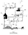
- FIG. 1 An example of a conventional but nevertheless efficient installation of electricity production from biomass is represented figure 1 .
- the boiler 12 is the place where the combustion of the biomass stored in a space 16 takes place.
- the heat produced makes it possible to vaporize liquid water with high pressure steam (40 to 110 bar) in a circuit 13, which supplies a turbine 131. driving an alternator 14 producing electricity.
- the circuit 13 is called the steam circuit, but it is also a water circuit since the steam is condensed in a part of the circuit.
- part of the steam can be extracted at an intermediate pressure (3 to 15 bar) to feed a steam consumer.
- the direct use of steam allows operation in cogeneration with simultaneous production of electricity and heat. It is one of the most energy efficient means, particularly suited to the big industrial consumption of a factory.
- the rest of the steam will relax at low pressure and low temperature (0.05 bar, at 30 ° C for example) and condense in a condenser 132, which rejects the heat of condensation of the steam environment. water.
- the liquid water (around 33 ° C) leaving the condenser 132 is then heated by steam extracted from the turbine 131 to go up to 90 ° C, then to 150 ° C at two "tarps" successive.
- the first cover 133 serves to collect and heat the liquid water from the condenser 132.
- the second cover 134 serves, being at higher pressure in the atmosphere, to remove by degassing gaseous impurities such as oxygen which infiltrate into the the water system and may corrode the boiler. Alternatively, depending on the size of the installation, there is only the degassing tarpaulin 134 or on the contrary several tarpaulins of reheating.
- the preheated liquid water is finally reinjected into the boiler 12, for example by means of a liquid pump 135, to be vaporized therein.
- the fumes exit the boiler 12 and enter the evacuation system 11. They pass successively through a cyclone 112 designed to remove large dust, then a filter 113 (with handle or electrofilter) to complete the purification of the flue gases before leaving the chimney 115 via a draft fan 114.
- the fumes still contain a significant energy that would be worthwhile to value. This lost energy is decomposed into sensible heat (heat due to the high temperature of the fumes) and latent heat (heat due to the gaseous state of the steam, more energetic than the liquid state) which represent (depending on the fuels) about 10 % and 10% of the power supplied by the fuel.
- Newer systems like the one described in the patents EP0857923 allow to do without an exchanger using hygroscopic solutions injected into the fumes.
- the solution heats and absorbs water vapor as it falls, and thus recovers both sensible heat and latent heat.
- the presence of calcium in the hygroscopic salt has a known effect of absorption of sulfur and its oxides SO2, SO3, H2SO4, which reduces post-treatment corrosion problems.
- the system described in the patent DE3916705 provides a first solution to this problem by proposing a hygroscopic solution system that does not require a boiler. Thanks to a particular construction, the solution successively undergoes a water vapor absorption phase, then an evaporation phase during its fall. The balance is therefore zero for the latent heat, only sensible heat (which represents less energy than the latent heat) is recovered.
- the invention proposes to overcome these disadvantages by providing a device for recovering the sensible energy and latent fumes without itself requiring an external energy supply.
- the device according to the invention makes it possible to use a hygroscopic solution while regenerating it without requiring any energy supply. It allows a flexibility of use compatible with a variable consumption of vapor.
- the device according to the invention makes it possible, by its architecture, to efficiently transfer to the plant's steam circuit both the latent heat and the sensible heat of the fumes.
- the invention proposes a thermal power generation plant comprising a boiler, smoke evacuation means including a duct, a steam circuit on which at least one steam turbine and a condenser are arranged, an alternator driven by the turbine, the installation being characterized in that it further comprises a heat recovery device in the fumes according to the first aspect of the invention.
- the method according to the invention is advantageously completed by a heat transfer step from the hygroscopic solution reconcentrated towards the steam circuit at an exchanger.
- a device 20 according to the invention integrated in a biomass electric production plant 10 is represented figure 2 .
- the flue gas heat recovery device according to the invention is particularly applicable to biomass combustion plants, but it is not limited to them since it also applies to all thermal power plants. that is, all plants that produce electricity directly or indirectly from a heat source driving a turbine, including gas, coal, hydrocarbon ...
- the device 20 comprises a circuit 21 which conveys a hygroscopic solution by means of one or more liquid pumps 210. In the event of uncertainty, this circuit will be designated as the main circuit of the device 20.
- the solution consists of a hygroscopic element, which will be referred to as the general term "salt", dissolved in water.
- s may be an aqueous solution of calcium chloride, lithium bromide, lithium chloride or triethylene glycol. These elements have a high affinity with water. As a result, they absorb water vapor at a higher temperature than that at which the vapor would normally condense (dew point). Symmetrically, these solutions boil at a temperature higher than that of pure water. As an indication, for a 50% by weight solution of calcium chloride in water, the curve "boiling temperature as a function of pressure" is shifted by about 20 degrees with respect to the water. pure.
- the smoke evacuation means 11 sees the addition of a preferentially vertical duct 111. It is added a means 23 for injecting a hygroscopic solution from the circuit 21, for example a fogger or a packed column. which sprays it in the conduit 111, most often at the top, to fall back into the conduit against the flue gas for better absorption.
- a hygroscopic solution from the circuit 21, for example a fogger or a packed column. which sprays it in the conduit 111, most often at the top, to fall back into the conduit against the flue gas for better absorption.
- the heat contained in these fumes in the form of latent heat of water vapor and sensible heat is thus transferred into the solution that heats and dilutes while the fumes cool and dry.
- the dilute solution carrying the heat extracted by absorption of water vapor in the gas, is recovered generally at the base of the conduit 111 through a means 24 of liquid extraction, which can simply be a bung.
- the device 20 also comprises a means 25 for regenerating the solution s disposed on the circuit 21. In fact it is necessary to extract the water vapor recovered by the solution to transfer its energy to the steam circuit 13, and to be able to reuse the solution in a new injection cycle in line 111.
- the device according to the invention can do without this heating step by using the physical properties of so-called saturated vapor pressure (Psat).
- Psat saturated vapor pressure
- the idea of the invention is to remark that it has approximately 25 ° C difference in boiling temperature between solution hygroscopic and pure water, but a unique condensation temperature, that of water.
- This relation means that, provided that the difference in temperature is greater than the difference in boiling temperature (here 25 ° C. + 5 ° C. creating a "driving force"), by bringing the gas phase of the solution with a watertight wall behind which cold water from the condenser circulates, spontaneous vaporization of the water contained in the solution s, and its condensation against the wall. Indeed, since the vapor phase of the solution s and the water that recondense is the same, the partial pressure is the same.
- the invention proposes two ingenious ways to speed up this process.
- the means 25 may be a low pressure vessel. It is composed of two chambers in which there is a high vacuum, for example 0.03 bar, one being in contact with the cold water of the condenser, and the other receiving the solution s. Thanks to this low pressure, the boiling temperature decreases sharply, and vaporization and then recondensation are almost instantaneous.
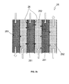
- the invention proposes, in a preferred embodiment, the use of a distillation membrane absorber, shown in FIG. figure 3a , or a combination of such an absorber and the previous enclosure.
- These membranes 26 have the property of being both hydrophobic (thus not permitting liquid water) and permeable to water vapor.
- the best known example of one of these materials that can constitute these membranes is Gore-Tex® marketed by WL Gore & Associates.
- This fabric based on stretched ethylene tetrafluoride, has 1.4 ⁇ 10 9 nano-pores per square centimeter, each having a diameter of about 0.2 microns. They are therefore 20,000 times smaller than a drop of water but 700 times larger than a molecule of water alone. Water vapor, consisting of molecules far apart from each other has no trouble passing, unlike drops of water held by surface tension.
- a first particularly advantageous structure for the absorber is an alternation of parallel channels 251 and 252, in which the hygroscopic solution s and the pure water of the condenser respectively circulate, these channels being separated by a thin collector 253 which will collect the water recondensed.
- the wall separating a channel 251 and a collector 253 is a distillation membrane 26 whose thermal conductivity is as low as possible.
- the wall separating a channel 252 and a manifold 253 is a sealed wall having the highest possible thermal conductivity, for example a metal plate.
- the condensed water is then extracted from the device 25. It can be used in another device or discharged into a wastewater network.
- a second solution also very advantageous is to directly use an alternation of parallel channels 251 and 252 separated by a membrane 301 without manifold 253.
- the water vapor recondense directly into the water circuit.
- This system is even simpler mechanically, its structure is represented figure 3b .
- it is not the water of the circuit 13 which circulates in the channels 252, but that of a secondary circuit 13b engaged with the circuit 13 just after the condenser 132 through an exchanger.
- a secondary circuit 13b engaged with the circuit 13 just after the condenser 132 through an exchanger.
- This circuit 13b is advantageously also present in the case of a low pressure chamber as described above.
- the fluids are injected against the current.
- this difference only concerns both ends of the absorber, and two neighboring points separated only by the membrane will always have at least 40 ° C. gap, ie enough to maintain the transfer of steam.
- the outlet of the absorber all the latent heat recovered by the solution s has been transmitted to the steam circuit 13.
- an exchanger 27 is disposed between the circuits 21 and 13. Now that there is no longer a need for a heat differential to allow regeneration of the solution s, the remaining heat can be transferred, that is, that is sensible heat, to the steam circuit water 13.
- the device 20 according to the invention is furthermore capable of adapting to variations in the consumer's consumption 15.
- the system may also be completed by a by-pass short-circuiting the conduit 111 making it possible to control the quantity of solution injected into the fumes with a constant flow rate, or any other system known to those skilled in the art.
- the impact of the device 20 according to the invention was evaluated on a small electrical installation of 3MW, and the graphs of the Figures 4a and 4b show the effectiveness of the hygroscopic solution on fumes.
- An injection of hygroscopic solution in the chimney at a height of 5m was taken into account on the model.
- the smoke enters at 180 ° C. It encounters the solution injected at 60 ° C.
- the respective evolution of the temperatures is visible on the figure 4a .
- At the top of the chimney all the sensible heat of the steam was absorbed since it is only at 60 ° C. In contrast, the solution was recovered at 80 ° C.
- the boiler of such an installation produces about 20T of steam per hour. Assuming that half is taken by the consumer customer and that the minimum is taken to preheat the condensate, it remains classically 7.56T of steam per hour available per hour for electricity production, tonnage increased to 8.45 to the invention.
- This valuation allows a direct gain of 78 kW of electricity production. It may seem modest when we actually recover 610 kW thermal in the smoke, but at the price of electricity "green" today, the gain in turnover on the sale of electricity reaches 78 000 euros over 8000 hours / year of production.
Landscapes
- Engineering & Computer Science (AREA)
- Chemical & Material Sciences (AREA)
- Mechanical Engineering (AREA)
- General Engineering & Computer Science (AREA)
- Analytical Chemistry (AREA)
- General Chemical & Material Sciences (AREA)
- Oil, Petroleum & Natural Gas (AREA)
- Chemical Kinetics & Catalysis (AREA)
- Combustion & Propulsion (AREA)
- Engine Equipment That Uses Special Cycles (AREA)
Abstract
Description
La présente invention concerne un dispositif améliorant les rendements des centrales thermiques.The present invention relates to a device improving the efficiency of thermal power plants.
Plus précisément, elle concerne l'application d'un dispositif de récupération de la chaleur latente contenue dans la vapeur d'eau de gaz chauds et humides des les fumées de combustion à la production d'électricité par biomasse, fonctionnant avec une turbine à vapeur dite à « condensation »More specifically, it relates to the application of a latent heat recovery device contained in the steam of hot and humid gases from the combustion fumes to the production of electricity by biomass, operating with a steam turbine said to "condensation"
Le terme de biomasse regroupe l'ensemble des matières organiques pouvant devenir des sources d'énergie. Ces matières organiques qui proviennent des plantes sont une forme de stockage de l'énergie solaire, captée et utilisée par les plantes grâce à la chlorophylle. Utilisée soit directement, soit après des transformations chimiques comme une méthanisation, la biomasse libère de l'énergie thermique en brulant. Dans le cas d'une centrale à biomasse, cette énergie thermique est classiquement convertie en électricité via une turbine à vapeur et un alternateur.The term biomass includes all organic materials that can become sources of energy. These organic materials that come from plants are a form of storage of solar energy, captured and used by plants through chlorophyll. Used either directly or after chemical transformations such as anaerobic digestion, biomass releases heat energy by burning. In the case of a biomass plant, this thermal energy is conventionally converted into electricity via a steam turbine and an alternator.
Bien que la combustion de biomasse s'accompagne comme pour le charbon, le gaz ou le pétrole de libération de carbone, il ne faut pas oublier que le carbone stocké dans la biomasse a récemment été extrait de l'atmosphère par la photosynthèse des plantes ou algues, alors que ce processus a eu lieu il y a des millions d'années pour les ressources fossiles. C'est pourquoi l'énergie tirée de la biomasse est considérée comme une énergie renouvelable, au sens premier du terme : si la surface dévolue à la culture de biomasse reste constante et la quantité prélevée est replantée, il y a renouvellement de l'énergie et le cycle du carbone est constant.Although biomass burning is accompanied as for coal, gas or oil release carbon, it should be remembered that the carbon stored in biomass has recently been extracted from the atmosphere by photosynthesis of plants or algae, while this process took place millions of years ago for fossil resources. This is why biomass energy is considered as renewable energy, in the first sense of the term: if the area devoted to the biomass culture remains constant and the quantity harvested is replanted, there is renewal of energy. and the carbon cycle is constant.
Cependant, la biomasse est une énergie chère qui peut avoir un bilan carbone désastreux si elle est mal utilisée. Il convient d'optimiser au maximum le rendement énergétique pour des raisons autant économiques qu'environnementales.However, biomass is an expensive energy that can have a disastrous carbon footprint if it is misused. Maximize energy efficiency for both economic and environmental reasons.
Un exemple d'une installation 10 classique mais néanmoins performante de production d'électricité à partir de la biomasse est représentée
La chaudière 12 est le lieu où se déroule la combustion de la biomasse stockée dans un espace 16. La chaleur produite permet la vaporisation d'eau liquide en vapeur haute pression (40 à 110 bar) dans un circuit 13, qui alimente une turbine 131 entraînant un alternateur 14 produisant l'électricité. On appelle le circuit 13 circuit de vapeur, mais c'est également un circuit d'eau puisque la vapeur est condensée dans une partie du circuit.The
Dans ce type d'installation optimisée, une partie de la vapeur peut être extraite à une pression intermédiaire (3 à 15 bar) pour alimenter un client 15 consommateur de vapeur. L'utilisation directe de la vapeur permet un fonctionnement en cogénération avec production simultanée d'électricité et de chaleur. C'est un moyen parmi les plus efficaces énergétiquement, particulièrement adapté à la grosse consommation industrielle d'une usine.In this type of optimized plant, part of the steam can be extracted at an intermediate pressure (3 to 15 bar) to feed a steam consumer. The direct use of steam allows operation in cogeneration with simultaneous production of electricity and heat. It is one of the most energy efficient means, particularly suited to the big industrial consumption of a factory.
Le reste de la vapeur va se détendre à basse pression et basse température (0,05 bar, à 30°C par exemple) et se condenser dans un condenseur 132, qui rejette à l'environnement la chaleur de condensation de la vapeur d'eau. L'eau liquide (autour de 33°C) sortant du condenseur 132 est alors réchauffée par de la vapeur extraite de la turbine 131 pour la remonter à 90°C, puis à 150°C au niveau de deux « bâches » successives.The rest of the steam will relax at low pressure and low temperature (0.05 bar, at 30 ° C for example) and condense in a
La première bâche 133 sert à recueillir et réchauffer l'eau liquide provenant du condenseur 132. La deuxième bâche 134 sert, en étant à pression supérieure à l'atmosphère, à éliminer par dégazage des impuretés gazeuses tel l'oxygène qui s'infiltrent dans le réseau d'eau et risquent de corroder la chaudière. Alternativement, suivant la taille de l'installation, il n'y a que la bâche dégazeuse 134 ou au contraire plusieurs bâches de réchauffage. L'eau liquide préchauffée est enfin réinjectée dans la chaudière 12, par exemple grâce à une pompe liquide 135, pour y être vaporisée.The
A l'autre extrémité de la centrale, les fumées sortent de la chaudière 12 et entrent dans le système d'évacuation 11. Elles passent successivement à travers un cyclone 112 conçu pour éliminer les poussières de taille importante, puis un filtre 113 (à manche ou électrofiltre) pour compléter l'épuration des fumées avant sortie par la cheminée 115 via un ventilateur de tirage 114.At the other end of the plant, the fumes exit the
Une des spécificités de la combustion de la biomasse (bois, pailles,...) est la présence de soufre dans le combustible végétal, que l'on retrouve dans les fumées. Celui-ci réagit avec l'oxygène encore présent dans les fumées pour former du S03 qui réagit ensuite avec l'eau pour former de l'acide sulfurique H2S04.One of the specificities of the combustion of biomass (wood, straw, ...) is the presence of sulfur in the vegetable fuel, which is found in fumes. This reacts with the oxygen still present in the fumes to form SO 3, which then reacts with water to form sulfuric acid H 2 SO 4.
En dessous d'une température d'environ 150°C, appelée le « point de rosée acide », cet acide est susceptible de se condenser sur les parois des cheminées, et de les abimer très rapidement.Below a temperature of about 150 ° C, called the "acid dew point", this acid is likely to condense on the walls of chimneys, and damage them very quickly.
Mais comme les teneurs en soufre restent suffisamment faibles pour ne pas nécessiter un traitement d'épuration spécifique comme pour un incinérateur, les chaudières équipant ce type d'installation sont tout simplement conçues par leurs constructeurs de façon à rejeter des fumées à une température de 160 à 180°C.But as the sulfur content remains low enough not to require a specific treatment treatment as for an incinerator, the boilers equipping this type of installation are simply designed by their manufacturers to reject fumes at a temperature of 160 at 180 ° C.
A une température aussi élevée, les fumées contiennent encore une énergie importante qu'il serait intéressant de valoriser. Cette énergie perdue se décompose en chaleur sensible (chaleur due la température élevée des fumées) et en chaleur latente (chaleur due à l'état gazeux de la vapeur, plus énergétique que l'état liquide) qui représentent (selon les combustibles) environ 10 % et 10 % de la puissance apportée par le combustible.At a temperature as high, the fumes still contain a significant energy that would be worthwhile to value. This lost energy is decomposed into sensible heat (heat due to the high temperature of the fumes) and latent heat (heat due to the gaseous state of the steam, more energetic than the liquid state) which represent (depending on the fuels) about 10 % and 10% of the power supplied by the fuel.
Il serait possible de valoriser cette énergie "basse température" par le préchauffage de l'eau liquide sortant du condenseur. Cela éviterait d'utiliser de la vapeur pour ce faire, on augmenterait ainsi la quantité de vapeur passant par la turbine, d'où le rendement électrique. Diverses solutions sont proposées.It would be possible to enhance this "low temperature" energy by preheating the liquid water leaving the condenser. This would avoid using steam to do this, it would increase the amount of steam passing through the turbine, hence the electrical efficiency. Various solutions are proposed.
On peut tout d'abord utiliser un économiseur, c'est à dire un simple échangeur métallique dans lequel circulerait l'eau sortant du condenseur. Ce système classique remplit la fonction thermique demandée mais présente l'inconvénient d'un très lourd investissement. En effet la condensation progressive de l'acide sulfurique nécessite d'utiliser un matériau totalement inoxydable comme l'Inconel®, très cher. De plus, les échanges thermiques avec des fumées sur une interface solide s'avèrent très mauvais, et sont aggravés par l'encrassement progressif de l'échangeur, du fait des poussières et imbrulés de la combustion de biomasse solide.We can first use an economizer, ie a simple metal heat exchanger in which circulating water leaving the condenser. This conventional system fulfills the thermal function required but has the disadvantage of a very heavy investment. Indeed the progressive condensation of sulfuric acid requires the use of a completely stainless material such as Inconel®, very expensive. In addition, heat exchange with fumes on a solid interface is very poor, and are aggravated by progressive fouling of the exchanger, because of dust and unburned combustion of solid biomass.
Des systèmes plus récents comme celui décrit dans les brevets
En outre, la présence de calcium dans le sel hygroscopique (nitrate de calcium) a un effet connu d'absorption du soufre et de ses oxydes S02, SO3, H2SO4, qui diminue les problématiques de corrosion post traitement.In addition, the presence of calcium in the hygroscopic salt (calcium nitrate) has a known effect of absorption of sulfur and its oxides SO2, SO3, H2SO4, which reduces post-treatment corrosion problems.
Cependant, cette technologie n'est pas applicable telle quelle, puisqu'une source d'énergie est nécessaire pour faire bouillir la solution pour la reconcentrer. Cette énergie est en effet apportée soit par de la vapeur extraite de la turbine, et alors le but recherché qui est de maximaliser la quantité de vapeur traversant les étages basse pression de la turbine est anéanti, soit par une source extérieure (chaudière spécifique par exemple), au prix d'un lourd investissement et d'une consommation supplémentaire d'énergie, laquelle va aussi à l'encontre de l'objectif du système.However, this technology is not applicable as it is, since a source of energy is needed to boil the solution to reconcentrate it. This energy is in fact provided either by the steam extracted from the turbine, and then the objective sought which is to maximize the amount of steam passing through the low pressure stages of the turbine is destroyed, either by an external source (specific boiler for example ), at the cost of heavy investment and additional energy consumption, which is also contrary to the purpose of the system.
Le système décrit dans le brevet
De plus, une spécificité des cogénérations est que l'appel de vapeur du client "chaleur" peut varier significativement. Et ceci, sans que la chaudière fasse évoluer sa production de vapeur. Ceci entraine une variabilité importante de la quantité de vapeur passant dans le condenseur : celle-ci peut varier fréquemment du simple au double, multipliant d'autant l'énergie nécessaire à son réchauffage. Or ce système impose un équilibre entre les deux phases, et il n'y a de moyen possible de contrôle de l'énergie absorbée :
- si le
client 15 appelle plus de vapeur, il y en a moins qui transite par lecondenseur 132, et la demande "extérieure" en énergie baisse. La solution s hygroscopique peut alors monter en température et se concentrer. Le risque de cristallisation de la solution et de colmatage des tuyaux apparait. - si au contraire le
client 15 n'appelle plus de vapeur, toute la production de lachaudière 12 va vers lecondenseur 132, et la demande "extérieure" en énergie augmente. La solution s baisse en température et devient moins concentrée en sel, entraînant une variation de volume significative, jusqu'à +50% !
- if the
customer 15 calls for more steam, there is less that passes through thecondenser 132, and the "external" demand for energy drops. The hygroscopic solution can then rise in temperature and concentrate. The risk of crystallization of the solution and clogging of the pipes appears. - if on the contrary the
customer 15 no longer calls for steam, the entire production of theboiler 12 goes to thecondenser 132, and the "external" demand in energy increases. The solution decreases in temperature and becomes less concentrated in salt, resulting in a significant volume variation, up to + 50%!
Ces problèmes ne sont pas acceptables car ils ne sont pas compatibles avec une utilisation fiable et rentable du dispositif.These problems are not acceptable because they are not compatible with a reliable and cost-effective use of the device.
L'invention propose de pallier ces inconvénients en proposant un dispositif permettant de récupérer l'énergie sensible et latente des fumées sans nécessiter lui-même un apport d'énergie extérieure.The invention proposes to overcome these disadvantages by providing a device for recovering the sensible energy and latent fumes without itself requiring an external energy supply.
A cet effet, l'invention propose un dispositif de récupération de chaleur dans des fumées contenant de la vapeur d'eau, circulant dans un conduit, d'une installation thermique de production d'électricité comprenant un circuit de vapeur sur lequel sont disposés au moins une turbine à vapeur et un condenseur, le dispositif étant caractérisé en ce qu'il comprend :
- un circuit principal pour la circulation d'une solution hygroscopique ;
- un moyen d'injection liquide depuis le circuit principal vers le conduit, de sorte que la solution hygroscopique se dilue en absorbant la vapeur d'eau des fumées circulant dans le conduit ;
- un moyen d'extraction liquide depuis le conduit vers le circuit principal, de sorte que la solution hygroscopique est injectée dans le circuit principal après absorption de la vapeur d'eau ;
- un moyen de régénération de la solution alimenté par l'eau froide en sortie du condenseur.
- a main circuit for the circulation of a hygroscopic solution;
- a liquid injection means from the main circuit to the conduit, so that the hygroscopic solution is diluted by absorbing the steam of the flue gases flowing in the conduit;
- a liquid extraction means from the conduit to the main circuit, so that the hygroscopic solution is injected into the main circuit after absorption of the water vapor;
- means for regenerating the solution supplied with cold water at the outlet of the condenser.
Le dispositif selon l'invention est avantageusement complété par les caractéristiques suivantes, prises seules ou en une quelconque de leur combinaison techniquement possible :
- le moyen de régénération met en prise le circuit principal et le circuit de vapeur, la température du circuit principal étant supérieure à celle du circuit de vapeur majorée de la différence de température d'ébullition entre la solution hygroscopique et l'eau pure ;
- le moyen de régénération permet de transférer de l'humidité et/ou de la chaleur depuis la solution hygroscopique diluée extraite du conduit, vers l'eau froide en sortie du condenseur ;
- le moyen de régénération comprend une enceinte basse pression ;
- le moyen de régénération comprend un absorbeur à membranes de distillation ;
- ledit absorbeur à membranes de distillation est constitué de canaux alternés de solution hygroscopique et d'eau séparés par des collecteurs, les parois entre les canaux de solution et les collecteurs étant des membranes de distillation ;
- ledit absorbeur à membranes de distillation est constitué de canaux alternés de solution hygroscopique et d'eau séparés par des membranes de distillation, les deux fluides étant injectés en sens contraire ;
- il comprend un échangeur supplémentaire mettant en prise la solution régénérée et l'eau froide en sortie du moyende régénération.
- the regeneration means engages the main circuit and the steam circuit, the temperature of the main circuit being greater than that of the steam circuit plus the difference in boiling temperature between the hygroscopic solution and the pure water;
- the regeneration means makes it possible to transfer moisture and / or heat from the dilute hygroscopic solution extracted from the conduit to the cold water leaving the condenser;
- the regeneration means comprises a low pressure vessel;
- the regeneration means comprises a distillation membrane absorber;
- said distillation membrane absorber consists of alternating channels of hygroscopic solution and water separated by collectors, the walls between the solution channels and the collectors being distillation membranes;
- said distillation membrane absorber consists of alternating channels of hygroscopic solution and water separated by distillation membranes, the two fluids being injected in opposite directions;
- it comprises an additional exchanger putting the regenerated solution into contact with the cold water at the outlet of the regeneration medium.
Le dispositif selon l'invention permet d'utiliser une solution hygroscopique tout en la régénérant sans nécessiter le moindre apport énergétique. Il permet une souplesse d'utilisation compatible avec une consommation variable de vapeur.The device according to the invention makes it possible to use a hygroscopic solution while regenerating it without requiring any energy supply. It allows a flexibility of use compatible with a variable consumption of vapor.
Et de plus le dispositif selon l'invention permet par son architecture de transférer efficacement au circuit de vapeur de la centrale à la fois la chaleur latente et la chaleur sensible des fumées.And furthermore, the device according to the invention makes it possible, by its architecture, to efficiently transfer to the plant's steam circuit both the latent heat and the sensible heat of the fumes.
Ainsi il est possible de diminuer de 40 à 50 % la quantité de vapeur devant être extraite de la turbine pour réchauffer l'eau sortant du condenseur. Toute cette vapeur économisée entraîne un gain direct en production d'électricité, de l'ordre de 2 à 4 % de rendement électrique, d'où des gains économiques significatifs puisque c'est une énergie à très haute valeur ajoutée.Thus it is possible to reduce by 40 to 50% the amount of steam to be extracted from the turbine to heat the water leaving the condenser. All this saved steam leads to a direct gain in electricity production, of the order of 2 to 4% of electrical efficiency, resulting in significant economic gains since it is an energy with very high added value.
Selon un deuxième aspect, l'invention propose une installation thermique de production d'électricité comprenant une chaudière, des moyens d'évacuation des fumées dont un conduit , un circuit de vapeur sur lequel sont disposés au moins une turbine à vapeur et un condenseur, un alternateur entraîné par la turbine, l'installation étant caractérisée en ce qu'elle comprend en outre un dispositif de récupération de chaleur dans les fumées selon le premier aspect de l'invention.According to a second aspect, the invention proposes a thermal power generation plant comprising a boiler, smoke evacuation means including a duct, a steam circuit on which at least one steam turbine and a condenser are arranged, an alternator driven by the turbine, the installation being characterized in that it further comprises a heat recovery device in the fumes according to the first aspect of the invention.
L'invention propose également un procédé de récupération de chaleur dans des fumées contenant de la vapeur d'eau, circulant dans un conduit, d'une installation thermique de production d'électricité comprenant un circuit de vapeur sur lequel sont disposés au moins une turbine à vapeur et un condenseur, le procédé étant caractérisé en ce qu'il comprend les étapes de :
- injection d'une solution hygroscopique dans le conduit, de sorte que la solution hygroscopique se dilue en absorbant la vapeur d'eau des fumées circulant dans le conduit ;
- extraction de la solution depuis le conduit ;
- évaporation de la vapeur d'eau absorbée par la solution, puis condensation, au niveau d'un moyen de régénération dans lequel sont mis en prise la solution et de l'eau froide provenant du condenseur.
- injecting a hygroscopic solution into the duct, so that the hygroscopic solution is diluted by absorbing the steam of the flue gases circulating in the duct;
- extracting the solution from the conduit;
- evaporation of the water vapor absorbed by the solution, and then condensation, at a regeneration means in which the solution is put in contact with cold water coming from the condenser.
Le procédé selon est avantageusement complété par une étape de transfert thermique depuis la solution hygroscopique reconcentrée vers le circuit de vapeur au niveau d'un échangeur.The method according to the invention is advantageously completed by a heat transfer step from the hygroscopic solution reconcentrated towards the steam circuit at an exchanger.
D'autres caractéristiques, buts et avantages de l'invention ressortiront de la description qui suit, qui est purement illustrative et non limitative, et qui doit être lue en regard des dessins annexés sur lesquels :
- la
figure 1 précédemment décrite est un schéma d'une centrale thermique connue ; - la
figure 2 est un schéma d'une centrale thermique équipée d'un dispositif de récupération de chaleur selon l'invention ; - la
figure 3a est un schéma d'un premier mode de réalisation possible d'un absorbeur à membrane utilisé dans une variante préférée du dispositif de récupération de chaleur selon l'invention ; - la
figure 3b est un schéma d'un second mode de réalisation possible d'un absorbeur à membrane utilisé dans une variante préférée du dispositif de récupération de chaleur selon l'invention; - les
figures 4a-b sont deux graphiques représentant le profil typique des températures et de la concentration en sel d'une solution hygroscopique utilisée par l'invention tombant dans une cheminée de 5m dans laquelle circule des fumées à 180°C.
- the
figure 1 previously described is a diagram of a known thermal power plant; - the
figure 2 is a diagram of a thermal power plant equipped with a heat recovery device according to the invention; - the
figure 3a is a diagram of a first possible embodiment of a membrane absorber used in a preferred variant of the heat recovery device according to the invention; - the
figure 3b is a diagram of a second possible embodiment of a membrane absorber used in a preferred variant of the heat recovery device according to the invention; - the
Figures 4a-b are two graphs representing the typical temperature and salt concentration profile of a hygroscopic solution used by the invention falling into a 5m chimney in which flue gas circulates at 180 ° C.
Sur les différentes figures, les éléments similaires portent les mêmes références numériques, et les valeurs de températures indiquées sont uniquement à titre d'exemple non limitatif.In the various figures, the similar elements bear the same numerical references, and the temperature values indicated are only by way of non-limiting example.
Un dispositif 20 selon l'invention intégré dans une installation thermique de production électrique 10 à biomasse est représenté
On retrouve les éléments connus d'une centrale à biomasse représentée
Le dispositif 20 selon l'invention comprend un circuit 21 qui véhicule une solution s hygroscopique grâce à une ou plusieurs pompes liquide 210. En cas d'incertitude, ce circuit sera désigné en tant que circuit principal du dispositif 20.The
La solution s est constituée d'un élément hygroscopique, que l'on désignera par le terme général de « sel », dissout dans l'eau. Par exemple, de manière non limitative, s peut être une solution aqueuse de chlorure de calcium, de bromure de lithium, de chlorure de lithium ou de triéthylène glycol. Ces éléments présentent une grande affinité avec l'eau. En conséquence, ils absorbent de la vapeur d'eau à une température supérieure à celle à laquelle la vapeur se condenserait normalement (point de rosée). Symétriquement, ces solutions bouillent à une température supérieure à celle de l'eau pure. A titre indicatif, pour une solution à 50 % massique de chlorure de calcium dans de l'eau, la courbe "température d'ébullition en fonction de la pression", est décalée d'une vingtaine de degrés par-rapport à l'eau pure.The solution consists of a hygroscopic element, which will be referred to as the general term "salt", dissolved in water. For example, without limitation, s may be an aqueous solution of calcium chloride, lithium bromide, lithium chloride or triethylene glycol. These elements have a high affinity with water. As a result, they absorb water vapor at a higher temperature than that at which the vapor would normally condense (dew point). Symmetrically, these solutions boil at a temperature higher than that of pure water. As an indication, for a 50% by weight solution of calcium chloride in water, the curve "boiling temperature as a function of pressure" is shifted by about 20 degrees with respect to the water. pure.
Le moyen 11 d'évacuation des fumées voit l'ajout d'un conduit préférentiellement vertical 111. On lui ajoute un moyen 23 d'injection d'une solution s hygroscopique depuis le circuit 21, par exemple un brumisateur ou une colonne à garnissage, qui la pulvérise dans le conduit 111, le plus souvent au sommet, pour retomber dans le conduit à contre-courant des fumées pour une meilleure absorption. La chaleur contenue dans ces fumées sous forme de chaleur latente de la vapeur d'eau et de chaleur sensible est ainsi transférée dans la solution qui chauffe et se dilue tandis que les fumées se refroidissent et s'assèchent.The smoke evacuation means 11 sees the addition of a preferentially
La solution s diluée, porteuse de la chaleur extraite par absorption de la vapeur d'eau dans le gaz, est récupérée généralement à la base du conduit 111 grâce à un moyen 24 d'extraction liquide, qui peut simplement être une bonde.The dilute solution, carrying the heat extracted by absorption of water vapor in the gas, is recovered generally at the base of the
Le dispositif 20 comprend également un moyen 25 de régénération de la solution s disposé sur le circuit 21. En effet il est nécessaire d'extraire la vapeur d'eau récupérée par la solution pour transférer son énergie au circuit de vapeur 13, et pour pouvoir réutiliser la solution dans un nouveau cycle d'injection dans le conduit 111.The
Cependant, il est théoriquement nécessaire de faire chauffer cette solution s diluée, pour en extraire la vapeur d'eau. Le dispositif selon l'invention arrive à se passer de cette étape de chauffage en utilisant les propriétés physiques de ce que l'on appelle la pression de vapeur saturante (Psat). Il s'agit de la pression à laquelle la phase gazeuse d'une substance est en équilibre avec sa phase liquide ou solide. Elle dépend exclusivement de la température. Dans le cas de l'eau, si la pression partielle de vapeur est supérieure à Psat, alors la vapeur va se condenser, et au contraire l'eau va se vaporiser dans le cas inverse. Cela explique pourquoi l'eau s'évapore dans la plupart des cas sans être à 100°C, température à laquelle Psat passe au dessus de la pression atmosphérique, l'eau s'évaporant donc même dans une atmosphère saturée. L'idée de l'invention est de remarquer qu'il a à peu près 25°C d'écart de température d'ébullition entre solution hygroscopique et eau pure, mais une température de condensation unique, celle de l'eau.However, it is theoretically necessary to heat this diluted solution to extract the water vapor. The device according to the invention can do without this heating step by using the physical properties of so-called saturated vapor pressure (Psat). This is the pressure at which the gaseous phase of a substance is in equilibrium with its liquid or solid phase. It depends exclusively on the temperature. In the case of water, if the vapor partial pressure is greater than Psat, then the vapor will condense, and instead the water will vaporize in the opposite case. This explains why the water evaporates in most cases without being at 100 ° C, the temperature at which Psat passes above atmospheric pressure, so the water evaporates even in a saturated atmosphere. The idea of the invention is to remark that it has approximately 25 ° C difference in boiling temperature between solution hygroscopic and pure water, but a unique condensation temperature, that of water.
En faisant des hypothèses de gaz parfait, d'après la formule de Clapeyron on a : 
- T0 : température d'ébullition de la substance à une pression p0 donnée, en K
- psat : pression de vapeur saturante, dans la même unité que p0
- M : masse molaire de la substance, en kg/mol
- Lv : chaleur latente de vaporisation de la substance, en J/kg
- R : constante des gaz parfaits, égale à 8,314 J/K/mol
- T : température de la vapeur, en K
- T 0 : Boiling temperature of the substance at a given pressure p 0 , in K
- p sat : saturation vapor pressure, in the same unit as p 0
- M: molar mass of the substance, in kg / mol
- L v : latent heat of vaporization of the substance, in J / kg
- R: perfect gas constant, equal to 8.314 J / K / mol
- T: steam temperature, in K
Dans notre cas, toutes les constantes sont égales entre l'eau et la solution s, à part la température d'ébullition.In our case, all the constants are equal between the water and the solution, except for the boiling point.
On a donc, en faisant un développement limité (car toutes les températures sont proches de 350K) : 
D'ou, Psateau < Psatsolution ⇔ ΔT0 < (Tsolution - Teau) Hence, Psat water <Psat solution ⇔ ΔT 0 <(T solution - T water )
Cette relation signifie qu'à condition que l'écart de température soit supérieur à l'écart de température d'ébullition (ici 25°C + 5°C créant une « force motrice »), en mettant en contact la phase gazeuse de la solution s avec une paroi étanche à l'eau derrière laquelle circule l'eau froide venant du condenseur, on aura spontanément une vaporisation de l'eau contenue dans la solution s, et sa condensation contre la paroi. En effet, puisque la phase vapeur de la solution s et de l'eau qui se recondense est la même, la pression partielle y est la même. Il sera donc impossible d'obtenir un équilibre, et on aura en permanence Psateau < Pvapeur < Psatsolution c'est-à-dire une condensation sur la paroi associée à un réchauffement d'après la première inégalité, et une vaporisation de la vapeur d'eau contenue dans la solution s associée à un refroidissement d'après la seconde inégalité. En pratique, la solution s arrive préchauffée par les vapeurs à 85°C, et l'eau refroidie par le condenseur à 33°C. Il y a donc un différentiel suffisant de 50°C. Il est toutefois nécessaire que la paroi présente une forte conductivité thermique pour que l'eau du condenseur puisse absorber la chaleur libérée par la condensation et la paroi reste froide.This relation means that, provided that the difference in temperature is greater than the difference in boiling temperature (here 25 ° C. + 5 ° C. creating a "driving force"), by bringing the gas phase of the solution with a watertight wall behind which cold water from the condenser circulates, spontaneous vaporization of the water contained in the solution s, and its condensation against the wall. Indeed, since the vapor phase of the solution s and the water that recondense is the same, the partial pressure is the same. It will therefore be impossible to obtain an equilibrium, and one will have permanently Psat water <P vapor <Psat solution that is to say a condensation on the wall associated with a warming according to the first inequality, and a vaporization of the water vapor contained in the solution s associated with a cooling according to the second inequality. In practice, the solution is preheated by the vapors at 85 ° C. and the water cooled by the condenser to 33 ° C. There is therefore a sufficient differential of 50 ° C. It is however necessary that the wall has a high thermal conductivity so that the water of the condenser can absorb the heat released by the condensation and the wall remains cold.
Cependant, il n'est pas concevable de réaliser ce transfert de vapeur dans une simple enceinte avec deux bacs. Il prendrait un temps bien trop long, et les températures se seraient équilibrées avant par conduction thermique. En effet les deux pressions saturantes restent très proches.However, it is not conceivable to carry out this transfer of steam in a simple enclosure with two bins. It would take a much longer time, and the temperatures would be balanced before by thermal conduction. Indeed the two saturating pressures remain very close.
L'invention propose deux façons ingénieuses d'accélérer ce processus.The invention proposes two ingenious ways to speed up this process.
Dans un premier mode de réalisation, le moyen 25 peut être une enceinte basse pression. Elle est composée de deux chambres dans lesquelles règne un vide poussé, par exemple 0.03 bars, l'une étant en contact avec l'eau froide du condenseur, et l'autre recevant la solution s. Grâce à cette faible pression la température d'ébullition diminue fortement, et la vaporisation puis la recondensation se font presque instantanément.In a first embodiment, the
Néanmoins, un tel système est contraignant à utiliser à cause des problèmes d'étanchéité.Nevertheless, such a system is restrictive to use because of sealing problems.
C'est pourquoi l'invention propose, dans un mode de réalisation préféré, d'utiliser un absorbeur à membranes de distillation, représenté sur la
En séparant les deux chambres par une telle membrane 26, la solution s va laisser « transpirer » son eau, qui se vaporise (production de froid), traverse la membrane, et se recondense quelques millimètres plus loin sur la paroi (production de chaud). Il y a ainsi interface quasi-directe entre les deux fluides. Une première structure particulièrement avantageuse pour l'absorbeur est une alternance de canaux parallèles 251 et 252, dans lesquels circulent respectivement la solution hygroscopique s et l'eau pure du condenseur, ces canaux étant séparés par un mince collecteur 253 qui va récupérer l'eau recondensée. La paroi qui sépare un canal 251 et un collecteur 253 est une membrane de distillation 26 dont la conductivité thermique est la plus faible possible. La paroi qui sépare un canal 252 et un collecteur 253 est une paroi étanche ayant la conductivité thermique la plus élevée possible, par exemple une plaque métallique. L'eau condensée est ensuite extraite du dispositif 25. Elle peut être utilisée dans un autre dispositif ou évacuée dans un réseau d'eaux usagées.By separating the two chambers by such a
Une seconde solution également très avantageuse est d'utiliser directement une alternance de canaux parallèles 251 et 252 séparés par une membrane 301 sans collecteur 253. La vapeur d'eau se recondense directement dans le circuit d'eau. Ce système est encore plus simple mécaniquement, sa structure est représentée
Avantageusement, dans un système à membranes comme dans l'autre, les fluides sont injectés à contre courant. Ainsi bien que leur écart de température diminue de plus de 10°C lors de la régénération, cet écart ne concerne que les deux extrémités de l'absorbeur, et deux points voisins séparés seulement par la membrane auront toujours au moins 40°C d'écart, c'est à dire assez pour entretenir le transfert de vapeur. En sortie de l'absorbeur, toute la chaleur latente récupérée par la solution s a été transmise au circuit de vapeur 13.Advantageously, in a membrane system as in the other, the fluids are injected against the current. Thus, although their temperature difference decreases by more than 10 ° C. during regeneration, this difference only concerns both ends of the absorber, and two neighboring points separated only by the membrane will always have at least 40 ° C. gap, ie enough to maintain the transfer of steam. At the outlet of the absorber, all the latent heat recovered by the solution s has been transmitted to the
On obtient donc de la solution s régénérée mais encore chaude. Avantageusement, un échangeur 27 est disposé entre les circuits 21 et 13. Maintenant qu'il n'y a plus besoin d'un différentiel de chaleur pour permettre la régénération de la solution s, on peut transférer la chaleur restante, c'est-à-dire la chaleur sensible, à l'eau de circuit de vapeur 13.So we get the solution s regenerated but still hot. Advantageously, an
Le dispositif 20 selon l'invention est en outre capable de s'adapter aux variations de consommation du client 15.The
Il suffit d'adapter le débit de solution s dans le circuit 21 au débit d'eau froide provenant du condenseur 132 dans le circuit 13, avantageusement en contrôlant la ou les pompes 210 disposées sur le circuit. On peut aussi éventuellement compléter le système par un by-pass court-circuitant le conduit 111 permettant de maîtriser la quantité se solution injectée dans les fumées à débit constant, ou tout autre système connu de l'homme du métier.It suffices to adapt the flow of solution s in the
L'impact du dispositif 20 selon l'invention a été évalué sur une petite installation électrique de 3MW, et les graphiques des
La suite de la simulation a consisté en l'utilisation de ces données pour prévoir le gain énergétique, et les résultats expérimentaux sont visibles sur la table 1. La colonne de gauche représente une installation classique, et celle de droite « PACO » est équipée du récupérateur de chaleur des fumées.
La chaudière d'une telle installation produit environ 20T de vapeur par heure. En faisant l'hypothèse que la moitié est prélevée par le client consommateur et que le minimum est prélevé pour préchauffer les condensats, il reste classiquement 7,56T de vapeur par heure disponible par heure pour la production électrique, tonnage monté à 8,45 grâce à l'invention.The boiler of such an installation produces about 20T of steam per hour. Assuming that half is taken by the consumer customer and that the minimum is taken to preheat the condensate, it remains classically 7.56T of steam per hour available per hour for electricity production, tonnage increased to 8.45 to the invention.
Cette valorisation permet un gain direct de 78 kW de production électrique. Il peut sembler modeste alors que l'on récupère en fait 610 kW thermique dans les fumées, mais au prix de l'électricité "verte" aujourd'hui, le gain de chiffre d'affaires sur la vente d'électricité atteint 78 000 euros sur 8000 heures/an de production.This valuation allows a direct gain of 78 kW of electricity production. It may seem modest when we actually recover 610 kW thermal in the smoke, but at the price of electricity "green" today, the gain in turnover on the sale of electricity reaches 78 000 euros over 8000 hours / year of production.
Claims (11)
Applications Claiming Priority (1)
| Application Number | Priority Date | Filing Date | Title |
|---|---|---|---|
| FR1050410A FR2955377B1 (en) | 2010-01-21 | 2010-01-21 | DEVICE AND METHOD FOR RECOVERING HEAT IN SMOKE FROM A THERMAL POWER PLANT |
Publications (2)
| Publication Number | Publication Date |
|---|---|
| EP2354710A1 true EP2354710A1 (en) | 2011-08-10 |
| EP2354710B1 EP2354710B1 (en) | 2013-06-12 |
Family
ID=42752055
Family Applications (1)
| Application Number | Title | Priority Date | Filing Date |
|---|---|---|---|
| EP11151147.3A Not-in-force EP2354710B1 (en) | 2010-01-21 | 2011-01-17 | Device and method for recovering heat from the fumes of a thermal power station |
Country Status (2)
| Country | Link |
|---|---|
| EP (1) | EP2354710B1 (en) |
| FR (1) | FR2955377B1 (en) |
Cited By (5)
| Publication number | Priority date | Publication date | Assignee | Title |
|---|---|---|---|---|
| WO2013043859A1 (en) * | 2011-09-23 | 2013-03-28 | Energy & Environmental Research Center | Water-saving liquid–gas processing system based on equilibrium moisture operation |
| EP2632571A1 (en) * | 2010-10-29 | 2013-09-04 | AAA Water Technologies AG | Apparatus for drying and/or cooling gas |
| EP2708276A1 (en) * | 2012-09-13 | 2014-03-19 | Nederlandse Organisatie voor toegepast -natuurwetenschappelijk onderzoek TNO | Improved membrane gas desorption |
| EP2708277A1 (en) * | 2012-09-13 | 2014-03-19 | Nederlandse Organisatie voor toegepast -natuurwetenschappelijk onderzoek TNO | Compact membrane gas desorption |
| CN110201498A (en) * | 2019-04-25 | 2019-09-06 | 上海海事大学 | A kind of desulfurization fume dehumidification system |
Families Citing this family (1)
| Publication number | Priority date | Publication date | Assignee | Title |
|---|---|---|---|---|
| JP6230344B2 (en) * | 2013-09-06 | 2017-11-15 | 株式会社東芝 | Steam turbine plant |
Citations (10)
| Publication number | Priority date | Publication date | Assignee | Title |
|---|---|---|---|---|
| US2324193A (en) * | 1940-06-21 | 1943-07-13 | Brunel Richard | Air conditioning |
| US4340572A (en) * | 1978-05-19 | 1982-07-20 | Woodside Construction, Inc. | Process for recovering heat from stack or flue gas |
| DE3916705A1 (en) | 1988-06-10 | 1989-12-14 | Inst Forsch Ration Zuckerind | Process for recovering heat from flue gases |
| FR2637510A1 (en) * | 1988-10-07 | 1990-04-13 | Meridional Oenologie Centre | Processes and devices for drying air at low temperature |
| DE4228471A1 (en) * | 1992-08-27 | 1994-03-03 | Henkel Kgaa | Flue gas desulfurization |
| FR2750346A1 (en) * | 1996-06-28 | 1998-01-02 | Realisations D Equipements Gaz | Separation of water from gases and regeneration of the liquids used in the treatment |
| EP0857923A2 (en) | 1997-02-10 | 1998-08-12 | BHF Verfahrenstechnik GmbH | Method of operating a condensing boiler and boiler for implementing said method |
| US20060156761A1 (en) * | 2003-07-15 | 2006-07-20 | Stefano Mola | Climate control system with a vapour compression circuit combined with an absorption circuit |
| EP1685890A1 (en) * | 2004-05-28 | 2006-08-02 | Westermark Energiutveckling AB | Method and device for heat recovery from moisture-laden gas by a hygroscopic medium |
| DE102007005578A1 (en) * | 2007-02-06 | 2008-08-07 | Bhf Verfahrenstechnik Gmbh | Exhaust gas desulfurization method, involves concentrating part of working solution in heated desorber before it is again supplied to solution, condensing produced desorber vapor, and delivering vapor as distillate |
-
2010
- 2010-01-21 FR FR1050410A patent/FR2955377B1/en not_active Expired - Fee Related
-
2011
- 2011-01-17 EP EP11151147.3A patent/EP2354710B1/en not_active Not-in-force
Patent Citations (10)
| Publication number | Priority date | Publication date | Assignee | Title |
|---|---|---|---|---|
| US2324193A (en) * | 1940-06-21 | 1943-07-13 | Brunel Richard | Air conditioning |
| US4340572A (en) * | 1978-05-19 | 1982-07-20 | Woodside Construction, Inc. | Process for recovering heat from stack or flue gas |
| DE3916705A1 (en) | 1988-06-10 | 1989-12-14 | Inst Forsch Ration Zuckerind | Process for recovering heat from flue gases |
| FR2637510A1 (en) * | 1988-10-07 | 1990-04-13 | Meridional Oenologie Centre | Processes and devices for drying air at low temperature |
| DE4228471A1 (en) * | 1992-08-27 | 1994-03-03 | Henkel Kgaa | Flue gas desulfurization |
| FR2750346A1 (en) * | 1996-06-28 | 1998-01-02 | Realisations D Equipements Gaz | Separation of water from gases and regeneration of the liquids used in the treatment |
| EP0857923A2 (en) | 1997-02-10 | 1998-08-12 | BHF Verfahrenstechnik GmbH | Method of operating a condensing boiler and boiler for implementing said method |
| US20060156761A1 (en) * | 2003-07-15 | 2006-07-20 | Stefano Mola | Climate control system with a vapour compression circuit combined with an absorption circuit |
| EP1685890A1 (en) * | 2004-05-28 | 2006-08-02 | Westermark Energiutveckling AB | Method and device for heat recovery from moisture-laden gas by a hygroscopic medium |
| DE102007005578A1 (en) * | 2007-02-06 | 2008-08-07 | Bhf Verfahrenstechnik Gmbh | Exhaust gas desulfurization method, involves concentrating part of working solution in heated desorber before it is again supplied to solution, condensing produced desorber vapor, and delivering vapor as distillate |
Cited By (10)
| Publication number | Priority date | Publication date | Assignee | Title |
|---|---|---|---|---|
| EP2632571A1 (en) * | 2010-10-29 | 2013-09-04 | AAA Water Technologies AG | Apparatus for drying and/or cooling gas |
| US9625194B2 (en) | 2010-10-29 | 2017-04-18 | Major Bravo Limited | Apparatus for drying and/or cooling gas |
| EP2632571B1 (en) * | 2010-10-29 | 2017-06-28 | Major Bravo Limited | Apparatus for drying and/or cooling gas |
| WO2013043859A1 (en) * | 2011-09-23 | 2013-03-28 | Energy & Environmental Research Center | Water-saving liquid–gas processing system based on equilibrium moisture operation |
| US8628603B2 (en) | 2011-09-23 | 2014-01-14 | Energy & Enviromental Research Center Foundation | Water-saving liquid-gas conditioning system |
| EP2708276A1 (en) * | 2012-09-13 | 2014-03-19 | Nederlandse Organisatie voor toegepast -natuurwetenschappelijk onderzoek TNO | Improved membrane gas desorption |
| EP2708277A1 (en) * | 2012-09-13 | 2014-03-19 | Nederlandse Organisatie voor toegepast -natuurwetenschappelijk onderzoek TNO | Compact membrane gas desorption |
| WO2014042530A1 (en) * | 2012-09-13 | 2014-03-20 | Nederlandse Organisatie Voor Toegepast-Natuurwetenschappelijk Onderzoek Tno | Improved membrane gas desorption |
| WO2014042529A1 (en) * | 2012-09-13 | 2014-03-20 | Nederlandse Organisatie Voor Toegepast-Natuurwetenschappelijk Onderzoek Tno | Compact membrane gas desorption |
| CN110201498A (en) * | 2019-04-25 | 2019-09-06 | 上海海事大学 | A kind of desulfurization fume dehumidification system |
Also Published As
| Publication number | Publication date |
|---|---|
| EP2354710B1 (en) | 2013-06-12 |
| FR2955377B1 (en) | 2012-03-16 |
| FR2955377A1 (en) | 2011-07-22 |
Similar Documents
| Publication | Publication Date | Title |
|---|---|---|
| EP2354710B1 (en) | Device and method for recovering heat from the fumes of a thermal power station | |
| RU2495707C2 (en) | Method and device for separation of carbon dioxide from offgas at electric power station running on fossil fuel | |
| WO2015110760A1 (en) | Facility and method for treating water pumped in a natural environment by evaporation/condensation | |
| FR2511885A1 (en) | METHOD FOR SEPARATING ELECTROLYTE VAPOR FROM A GAS STREAM CONTAINING WATER VAPOR | |
| US20100139536A1 (en) | Method and plant for co2 capturing | |
| EP0148756B1 (en) | System for the revaluation of low-level thermal energy using phenomena of evaporation, and solution of two fluids being in equilibrium of vapour pressure at different temperatures | |
| FR2979974A3 (en) | METHOD AND SYSTEM FOR TREATING COMBUSTION GAS FROM A HEAT SOURCE | |
| EP2918911B1 (en) | Combustion process in thermal combustion plant | |
| WO2013182604A2 (en) | Thermal plant for the combustion of wet biomass | |
| WO2014096736A1 (en) | Device and method for evaporating a liquid, and applications of said device and method | |
| EP1275429B1 (en) | Process and device for the capture of vapors contained in a gas effluent | |
| WO2017103547A1 (en) | Membrane regeneration system for an acid gas capture solvent | |
| EP0147770B1 (en) | Thermal induction machine | |
| EP2829312B1 (en) | Device for capturing acid gas contained in combustion fumes | |
| FR2872886A1 (en) | METHOD AND DEVICE FOR GENERATING WATER VAPOR ADAPTED TO OXY-COMBUSTION | |
| FR2983901A1 (en) | Thermal installation for production of electricity by combustion of e.g. biomass, has vapor circuit leveled with overheating exchanger that is placed between set of turbines, and overheating exchanger allowing rise in temperature of steam | |
| EP3724471A1 (en) | Improved system for storing and harvesting energy | |
| FR3081108A1 (en) | PROCESS FOR TREATING SMOKE GENERATED BY WOOD COMBUSTION AND DEVICE FOR IMPLEMENTING THE METHOD. | |
| WO2023110329A1 (en) | Facility for cooling a gas flow containing co2 and method using such a facility | |
| FR3005143A1 (en) | THERMAL INSTALLATION FOR THE PRODUCTION OF ELECTRICITY BY COMBUSTION | |
| EP2354701A2 (en) | Enhanced device and method for recovering heat from a gas containing water vapour | |
| JP2010151112A (en) | Oxygen burning co2 recovery turbine system | |
| EP3022409B1 (en) | Thermal plant for the combustion of biomass in cogeneration, and method of heat transfer | |
| EP4424406A1 (en) | Method and apparatus for scrubbing a gas stream | |
| JP2010266091A (en) | Intermediate-temperature heat dissolution type refrigeration heat engine evaporating concentrating device |
Legal Events
| Date | Code | Title | Description |
|---|---|---|---|
| PUAI | Public reference made under article 153(3) epc to a published international application that has entered the european phase |
Free format text: ORIGINAL CODE: 0009012 |
|
| 17P | Request for examination filed |
Effective date: 20110117 |
|
| AK | Designated contracting states |
Kind code of ref document: A1 Designated state(s): AL AT BE BG CH CY CZ DE DK EE ES FI FR GB GR HR HU IE IS IT LI LT LU LV MC MK MT NL NO PL PT RO RS SE SI SK SM TR |
|
| AX | Request for extension of the european patent |
Extension state: BA ME |
|
| GRAP | Despatch of communication of intention to grant a patent |
Free format text: ORIGINAL CODE: EPIDOSNIGR1 |
|
| GRAS | Grant fee paid |
Free format text: ORIGINAL CODE: EPIDOSNIGR3 |
|
| GRAA | (expected) grant |
Free format text: ORIGINAL CODE: 0009210 |
|
| AK | Designated contracting states |
Kind code of ref document: B1 Designated state(s): AL AT BE BG CH CY CZ DE DK EE ES FI FR GB GR HR HU IE IS IT LI LT LU LV MC MK MT NL NO PL PT RO RS SE SI SK SM TR |
|
| REG | Reference to a national code |
Ref country code: GB Ref legal event code: FG4D Free format text: NOT ENGLISH |
|
| REG | Reference to a national code |
Ref country code: CH Ref legal event code: EP |
|
| REG | Reference to a national code |
Ref country code: AT Ref legal event code: REF Ref document number: 616838 Country of ref document: AT Kind code of ref document: T Effective date: 20130615 |
|
| REG | Reference to a national code |
Ref country code: IE Ref legal event code: FG4D Free format text: LANGUAGE OF EP DOCUMENT: FRENCH |
|
| REG | Reference to a national code |
Ref country code: DE Ref legal event code: R096 Ref document number: 602011001973 Country of ref document: DE Effective date: 20130808 |
|
| PG25 | Lapsed in a contracting state [announced via postgrant information from national office to epo] |
Ref country code: GR Free format text: LAPSE BECAUSE OF FAILURE TO SUBMIT A TRANSLATION OF THE DESCRIPTION OR TO PAY THE FEE WITHIN THE PRESCRIBED TIME-LIMIT Effective date: 20130913 Ref country code: ES Free format text: LAPSE BECAUSE OF FAILURE TO SUBMIT A TRANSLATION OF THE DESCRIPTION OR TO PAY THE FEE WITHIN THE PRESCRIBED TIME-LIMIT Effective date: 20130923 Ref country code: LT Free format text: LAPSE BECAUSE OF FAILURE TO SUBMIT A TRANSLATION OF THE DESCRIPTION OR TO PAY THE FEE WITHIN THE PRESCRIBED TIME-LIMIT Effective date: 20130612 Ref country code: SI Free format text: LAPSE BECAUSE OF FAILURE TO SUBMIT A TRANSLATION OF THE DESCRIPTION OR TO PAY THE FEE WITHIN THE PRESCRIBED TIME-LIMIT Effective date: 20130612 Ref country code: NO Free format text: LAPSE BECAUSE OF FAILURE TO SUBMIT A TRANSLATION OF THE DESCRIPTION OR TO PAY THE FEE WITHIN THE PRESCRIBED TIME-LIMIT Effective date: 20130912 Ref country code: SE Free format text: LAPSE BECAUSE OF FAILURE TO SUBMIT A TRANSLATION OF THE DESCRIPTION OR TO PAY THE FEE WITHIN THE PRESCRIBED TIME-LIMIT Effective date: 20130612 Ref country code: FI Free format text: LAPSE BECAUSE OF FAILURE TO SUBMIT A TRANSLATION OF THE DESCRIPTION OR TO PAY THE FEE WITHIN THE PRESCRIBED TIME-LIMIT Effective date: 20130612 |
|
| REG | Reference to a national code |
Ref country code: AT Ref legal event code: MK05 Ref document number: 616838 Country of ref document: AT Kind code of ref document: T Effective date: 20130612 |
|
| REG | Reference to a national code |
Ref country code: NL Ref legal event code: VDEP Effective date: 20130612 |
|
| REG | Reference to a national code |
Ref country code: LT Ref legal event code: MG4D |
|
| PG25 | Lapsed in a contracting state [announced via postgrant information from national office to epo] |
Ref country code: HR Free format text: LAPSE BECAUSE OF FAILURE TO SUBMIT A TRANSLATION OF THE DESCRIPTION OR TO PAY THE FEE WITHIN THE PRESCRIBED TIME-LIMIT Effective date: 20130612 Ref country code: BG Free format text: LAPSE BECAUSE OF FAILURE TO SUBMIT A TRANSLATION OF THE DESCRIPTION OR TO PAY THE FEE WITHIN THE PRESCRIBED TIME-LIMIT Effective date: 20130912 Ref country code: RS Free format text: LAPSE BECAUSE OF FAILURE TO SUBMIT A TRANSLATION OF THE DESCRIPTION OR TO PAY THE FEE WITHIN THE PRESCRIBED TIME-LIMIT Effective date: 20130612 |
|
| PG25 | Lapsed in a contracting state [announced via postgrant information from national office to epo] |
Ref country code: LV Free format text: LAPSE BECAUSE OF FAILURE TO SUBMIT A TRANSLATION OF THE DESCRIPTION OR TO PAY THE FEE WITHIN THE PRESCRIBED TIME-LIMIT Effective date: 20130612 |
|
| PG25 | Lapsed in a contracting state [announced via postgrant information from national office to epo] |
Ref country code: PT Free format text: LAPSE BECAUSE OF FAILURE TO SUBMIT A TRANSLATION OF THE DESCRIPTION OR TO PAY THE FEE WITHIN THE PRESCRIBED TIME-LIMIT Effective date: 20131014 Ref country code: IS Free format text: LAPSE BECAUSE OF FAILURE TO SUBMIT A TRANSLATION OF THE DESCRIPTION OR TO PAY THE FEE WITHIN THE PRESCRIBED TIME-LIMIT Effective date: 20131012 Ref country code: CZ Free format text: LAPSE BECAUSE OF FAILURE TO SUBMIT A TRANSLATION OF THE DESCRIPTION OR TO PAY THE FEE WITHIN THE PRESCRIBED TIME-LIMIT Effective date: 20130612 Ref country code: SK Free format text: LAPSE BECAUSE OF FAILURE TO SUBMIT A TRANSLATION OF THE DESCRIPTION OR TO PAY THE FEE WITHIN THE PRESCRIBED TIME-LIMIT Effective date: 20130612 Ref country code: AT Free format text: LAPSE BECAUSE OF FAILURE TO SUBMIT A TRANSLATION OF THE DESCRIPTION OR TO PAY THE FEE WITHIN THE PRESCRIBED TIME-LIMIT Effective date: 20130612 Ref country code: EE Free format text: LAPSE BECAUSE OF FAILURE TO SUBMIT A TRANSLATION OF THE DESCRIPTION OR TO PAY THE FEE WITHIN THE PRESCRIBED TIME-LIMIT Effective date: 20130612 |
|
| PG25 | Lapsed in a contracting state [announced via postgrant information from national office to epo] |
Ref country code: RO Free format text: LAPSE BECAUSE OF FAILURE TO SUBMIT A TRANSLATION OF THE DESCRIPTION OR TO PAY THE FEE WITHIN THE PRESCRIBED TIME-LIMIT Effective date: 20130612 Ref country code: NL Free format text: LAPSE BECAUSE OF FAILURE TO SUBMIT A TRANSLATION OF THE DESCRIPTION OR TO PAY THE FEE WITHIN THE PRESCRIBED TIME-LIMIT Effective date: 20130612 Ref country code: PL Free format text: LAPSE BECAUSE OF FAILURE TO SUBMIT A TRANSLATION OF THE DESCRIPTION OR TO PAY THE FEE WITHIN THE PRESCRIBED TIME-LIMIT Effective date: 20130612 |
|
| PLBE | No opposition filed within time limit |
Free format text: ORIGINAL CODE: 0009261 |
|
| STAA | Information on the status of an ep patent application or granted ep patent |
Free format text: STATUS: NO OPPOSITION FILED WITHIN TIME LIMIT |
|
| PG25 | Lapsed in a contracting state [announced via postgrant information from national office to epo] |
Ref country code: DK Free format text: LAPSE BECAUSE OF FAILURE TO SUBMIT A TRANSLATION OF THE DESCRIPTION OR TO PAY THE FEE WITHIN THE PRESCRIBED TIME-LIMIT Effective date: 20130612 |
|
| 26N | No opposition filed |
Effective date: 20140313 |
|
| PG25 | Lapsed in a contracting state [announced via postgrant information from national office to epo] |
Ref country code: IT Free format text: LAPSE BECAUSE OF FAILURE TO SUBMIT A TRANSLATION OF THE DESCRIPTION OR TO PAY THE FEE WITHIN THE PRESCRIBED TIME-LIMIT Effective date: 20130612 |
|
| REG | Reference to a national code |
Ref country code: DE Ref legal event code: R097 Ref document number: 602011001973 Country of ref document: DE Effective date: 20140313 |
|
| BERE | Be: lapsed |
Owner name: PYRAINE Effective date: 20140131 |
|
| PG25 | Lapsed in a contracting state [announced via postgrant information from national office to epo] |
Ref country code: LU Free format text: LAPSE BECAUSE OF FAILURE TO SUBMIT A TRANSLATION OF THE DESCRIPTION OR TO PAY THE FEE WITHIN THE PRESCRIBED TIME-LIMIT Effective date: 20140117 |
|
| REG | Reference to a national code |
Ref country code: CH Ref legal event code: PL |
|
| PG25 | Lapsed in a contracting state [announced via postgrant information from national office to epo] |
Ref country code: LI Free format text: LAPSE BECAUSE OF NON-PAYMENT OF DUE FEES Effective date: 20140131 Ref country code: CH Free format text: LAPSE BECAUSE OF NON-PAYMENT OF DUE FEES Effective date: 20140131 |
|
| REG | Reference to a national code |
Ref country code: IE Ref legal event code: MM4A |
|
| REG | Reference to a national code |
Ref country code: FR Ref legal event code: PLFP Year of fee payment: 5 |
|
| PG25 | Lapsed in a contracting state [announced via postgrant information from national office to epo] |
Ref country code: IE Free format text: LAPSE BECAUSE OF NON-PAYMENT OF DUE FEES Effective date: 20140117 Ref country code: BE Free format text: LAPSE BECAUSE OF NON-PAYMENT OF DUE FEES Effective date: 20140131 |
|
| PG25 | Lapsed in a contracting state [announced via postgrant information from national office to epo] |
Ref country code: MC Free format text: LAPSE BECAUSE OF FAILURE TO SUBMIT A TRANSLATION OF THE DESCRIPTION OR TO PAY THE FEE WITHIN THE PRESCRIBED TIME-LIMIT Effective date: 20130612 |
|
| PGFP | Annual fee paid to national office [announced via postgrant information from national office to epo] |
Ref country code: FR Payment date: 20150114 Year of fee payment: 5 |
|
| GBPC | Gb: european patent ceased through non-payment of renewal fee |
Effective date: 20150117 |
|
| PG25 | Lapsed in a contracting state [announced via postgrant information from national office to epo] |
Ref country code: GB Free format text: LAPSE BECAUSE OF NON-PAYMENT OF DUE FEES Effective date: 20150117 |
|
| PG25 | Lapsed in a contracting state [announced via postgrant information from national office to epo] |
Ref country code: MT Free format text: LAPSE BECAUSE OF FAILURE TO SUBMIT A TRANSLATION OF THE DESCRIPTION OR TO PAY THE FEE WITHIN THE PRESCRIBED TIME-LIMIT Effective date: 20130612 |
|
| PG25 | Lapsed in a contracting state [announced via postgrant information from national office to epo] |
Ref country code: SM Free format text: LAPSE BECAUSE OF FAILURE TO SUBMIT A TRANSLATION OF THE DESCRIPTION OR TO PAY THE FEE WITHIN THE PRESCRIBED TIME-LIMIT Effective date: 20130612 |
|
| PGFP | Annual fee paid to national office [announced via postgrant information from national office to epo] |
Ref country code: DE Payment date: 20160212 Year of fee payment: 6 |
|
| PG25 | Lapsed in a contracting state [announced via postgrant information from national office to epo] |
Ref country code: CY Free format text: LAPSE BECAUSE OF FAILURE TO SUBMIT A TRANSLATION OF THE DESCRIPTION OR TO PAY THE FEE WITHIN THE PRESCRIBED TIME-LIMIT Effective date: 20130612 |
|
| PG25 | Lapsed in a contracting state [announced via postgrant information from national office to epo] |
Ref country code: TR Free format text: LAPSE BECAUSE OF FAILURE TO SUBMIT A TRANSLATION OF THE DESCRIPTION OR TO PAY THE FEE WITHIN THE PRESCRIBED TIME-LIMIT Effective date: 20130612 Ref country code: HU Free format text: LAPSE BECAUSE OF FAILURE TO SUBMIT A TRANSLATION OF THE DESCRIPTION OR TO PAY THE FEE WITHIN THE PRESCRIBED TIME-LIMIT; INVALID AB INITIO Effective date: 20110117 |
|
| REG | Reference to a national code |
Ref country code: FR Ref legal event code: ST Effective date: 20160930 |
|
| PG25 | Lapsed in a contracting state [announced via postgrant information from national office to epo] |
Ref country code: FR Free format text: LAPSE BECAUSE OF NON-PAYMENT OF DUE FEES Effective date: 20160201 |
|
| REG | Reference to a national code |
Ref country code: DE Ref legal event code: R119 Ref document number: 602011001973 Country of ref document: DE |
|
| PG25 | Lapsed in a contracting state [announced via postgrant information from national office to epo] |
Ref country code: DE Free format text: LAPSE BECAUSE OF NON-PAYMENT OF DUE FEES Effective date: 20170801 |
|
| PG25 | Lapsed in a contracting state [announced via postgrant information from national office to epo] |
Ref country code: MK Free format text: LAPSE BECAUSE OF FAILURE TO SUBMIT A TRANSLATION OF THE DESCRIPTION OR TO PAY THE FEE WITHIN THE PRESCRIBED TIME-LIMIT Effective date: 20130612 |
|
| PG25 | Lapsed in a contracting state [announced via postgrant information from national office to epo] |
Ref country code: AL Free format text: LAPSE BECAUSE OF FAILURE TO SUBMIT A TRANSLATION OF THE DESCRIPTION OR TO PAY THE FEE WITHIN THE PRESCRIBED TIME-LIMIT Effective date: 20130612 |