EP0857923A2 - Method of operating a condensing boiler and boiler for implementing said method - Google Patents
Method of operating a condensing boiler and boiler for implementing said method Download PDFInfo
- Publication number
- EP0857923A2 EP0857923A2 EP98102193A EP98102193A EP0857923A2 EP 0857923 A2 EP0857923 A2 EP 0857923A2 EP 98102193 A EP98102193 A EP 98102193A EP 98102193 A EP98102193 A EP 98102193A EP 0857923 A2 EP0857923 A2 EP 0857923A2
- Authority
- EP
- European Patent Office
- Prior art keywords
- solution
- desorber
- boiler
- absorber
- condenser
- Prior art date
- Legal status (The legal status is an assumption and is not a legal conclusion. Google has not performed a legal analysis and makes no representation as to the accuracy of the status listed.)
- Granted
Links
Images


Classifications
-
- F—MECHANICAL ENGINEERING; LIGHTING; HEATING; WEAPONS; BLASTING
- F24—HEATING; RANGES; VENTILATING
- F24H—FLUID HEATERS, e.g. WATER OR AIR HEATERS, HAVING HEAT-GENERATING MEANS, e.g. HEAT PUMPS, IN GENERAL
- F24H4/00—Fluid heaters characterised by the use of heat pumps
- F24H4/02—Water heaters
-
- F—MECHANICAL ENGINEERING; LIGHTING; HEATING; WEAPONS; BLASTING
- F24—HEATING; RANGES; VENTILATING
- F24H—FLUID HEATERS, e.g. WATER OR AIR HEATERS, HAVING HEAT-GENERATING MEANS, e.g. HEAT PUMPS, IN GENERAL
- F24H8/00—Fluid heaters characterised by means for extracting latent heat from flue gases by means of condensation
- F24H8/003—Fluid heaters characterised by means for extracting latent heat from flue gases by means of condensation having means for moistening the combustion air with condensate from the combustion gases
-
- Y—GENERAL TAGGING OF NEW TECHNOLOGICAL DEVELOPMENTS; GENERAL TAGGING OF CROSS-SECTIONAL TECHNOLOGIES SPANNING OVER SEVERAL SECTIONS OF THE IPC; TECHNICAL SUBJECTS COVERED BY FORMER USPC CROSS-REFERENCE ART COLLECTIONS [XRACs] AND DIGESTS
- Y02—TECHNOLOGIES OR APPLICATIONS FOR MITIGATION OR ADAPTATION AGAINST CLIMATE CHANGE
- Y02B—CLIMATE CHANGE MITIGATION TECHNOLOGIES RELATED TO BUILDINGS, e.g. HOUSING, HOUSE APPLIANCES OR RELATED END-USER APPLICATIONS
- Y02B30/00—Energy efficient heating, ventilation or air conditioning [HVAC]
Definitions
- the invention relates to a method for operating a boiler with condensing boiler use, furthermore a boiler with apparatus features to implement the method.
- Boilers in the sense of the invention are directly fired boilers for hot water, Hot water and steam generation as well as exhaust gas heat exchanger or waste heat boiler, which internal combustion systems (internal combustion engines, gas turbines or Fuel cells) are connected downstream.
- the state of the art in the field of condensing boilers is characterized by that the burner exhaust gas in the boiler or in a downstream of the boiler Heat exchanger unit through the cold heating return to below the dew point temperature of the gas is cooled and thus part of that contained in the flue gas Enthalpy of condensation of the exhaust gas is used to heat the heating return.
- the disadvantage of the condensing technology implemented in this way is that that the calorific value can only be used at low return temperatures, either for Low temperature heating systems or with low heat requirements in conventional heating networks can be done.
- only a small proportion of the actually in the flue gas contained water vapor condensed and used e.g. is in gas boilers at 50 ° C only about half of the water vapor contained in the flue gas condenses.
- condensing boilers At high return temperatures of the heating network, which are above the thaw temperature of the flue gas of approx. 50-60 ° C, condensing boilers also work like conventional ones Boiler.
- the proposed method has the advantage over conventional condensing boilers that that a larger proportion of the enthalpy of condensation contained in the flue gas is used can and this use of the calorific value even at high heating return temperatures
- Gas-heated absorption heat pumps are also known, in which a additional heat absorption from the environment the fuel expenditure for a given Heating power is reduced.
- the proposed condensing boiler has compared to gas-heated absorption heat pumps with integrated condensing technology the advantage that the absorption process only for Use of the residual smoke heat must be designed while the main part of the heat is generated by direct heat transfer in the boiler.
- the driving energy of the transformation process is the energy content of the Combustion gases limited.
- the improvement potential which in a changed process management of the Combustion process cannot be used by an external process.
- the moisture that can be extracted from the flue gas becomes limited by the energy content of the flue gases themselves (WP 211256) or it is a additional heating steam required (DD 280472) to absorb the absorbed moisture desorb again.
- the method described in (DD 280472) also has the Disadvantage that the solution initially in the sump of the absorber for useful heat extraction is cooled and then has to be regeneratively heated again.
- the proposed method has the advantage that through the direct coupling of the combustion and absorption cycle processes Outlet temperature of the flue gases from the boiler and the connected one Heat utilization process can be optimally coordinated, which makes it Heat utilization potential of the absorption cycle processes significantly increased.
- the one from the Flue gas can no longer be extracted due to the energy content of the flue gases limited.
- An advantageous division of the solution flows between absorber and desorber enables a better design of both devices and enables the downsizing or Saving of the regenerative heat exchanger without the thermodynamic effectiveness significantly reduce the cycle.
- the essence of the invention is in a boiler by integrating an open Sorption process to realize condensing at elevated temperature.
- the dehumidification and cooling of the flue gas takes place in the absorber.
- the solution is regenerated in the desorber, which is heated directly or indirectly by the combustion heat supply.
- the heating water return flow previously preheated in the absorber is further heated by the water vapor condensing in the condenser before it enters the boiler heat exchanger.
- the implementation of the process is not essential to the structural integration of the desorber tied in the cauldron.
- the desorber can also be heated externally by the Combustion gases from the boiler through a separate heat transfer circuit or Heat pipes or by steam or hot water coupling.
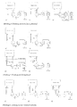
- the absorption can take place both with constant heat release (Figure 3a) and adiabatic ( Figures 3b and 3c). It is an advantage with an adiabatic device decouple the heat from the poor solution (aL) ( Figure 3c), since this is the least Temperature level is present and is therefore best adapted to the return temperature.
- the sorption process can be implemented by various circuits.
- Figure 4 shows the basic process in which the absorber and the desorber are involved in a solution cycle.
- the solution can be transported by one pump each for the poor and the rich solution stream (Figure 4a).
- the advantage this variant is that the desorber and the condenser on Ambient pressure level can be operated and the pumps not in suction mode work.
- the pressure level in the desorber or in the condenser is increased ( Figure 4b) or degraded ( Figure 4c), it is possible to run the solution with just a pump.
- the extraction of inert gases from the vacuum working capacitor can be done by using a blasting apparatus ( Figure 4c).
- Figure 5 shows the sorption process with a bypass circuit.
- This variant enables the absorber to be operated with larger solution circulations than the desorber. Larger solutions in the absorber allow a smaller design of the absorption apparatus. Due to a low solution circulation to the desorber and thus increased degassing widths, it is possible to increase efficiency by lower To achieve heat transfer losses in the solution heat exchanger (RWT) or smaller Use heat exchangers with the same efficiency.
- RWT solution heat exchanger
- FIG. 6 A circuit with two coupled solution circuits is shown in Figure 6.
- the desorber and absorber circuit are mixed with each other by a mixing section coupled.
- the desorber and the condenser can be operated under normal pressure with this variant.
- By using a Blasting apparatus it is possible to use this circuit variant with a pump which is only available in the Printing operation works to realize ( Figure 6c).
- FIG. 7 An embodiment according to the circuit in Figure 4a is in the Figure 7 shown.
- the arrangement of the devices and the utilization Thermo-physical laws make it possible to use the device without any supply to operate mechanical energy.
- the necessary delivery pressure for the solution flow from the absorber to the desorber (RH) is applied by the hydrostatic height difference between the two devices.
- the rising water vapor conveys the solution in the capillary tubes Drops of liquid with upwards.
- the capillary bundle can be outside the apparatus stand as well as in a compact form in the apparatus structure ( Figure 7).
- the design of the absorber as a trickling device makes it easy to separate the solution possible at the exhaust outlet, since there is no spraying of the solution.
- the condenser is operated in negative pressure, which is basically the case with all Circuit variants other than those shown in Fig. 4.b) and 5.b) is possible, so the Realize inert gas discharge through a special condensate drain in a simple manner.
- the condensate is drained through several capillary tubes Empty the condenser gas bubbles are trapped in the capillaries and thus are conveyed out of the condenser by the condensate running off.
Abstract
Description
Die Erfindung betrifft ein Verfahren zum Betrieb eines Heizkessels mit Brennwertnutzung, weiterhin einen Heizkessel mit apparativen Merkmalen zur Realisierung des Verfahrens. Heizkessel im Sinne der Erfindung sind direktbefeuerte Kessel zur Warmwasser-, Heißwasser- und Dampferzeugung sowie Abgaswärmetauscher bzw. Abhitzekessel, welche Verbrennungskraftanlagen (Verbrennungsmotoren, Gasturbinen oder Brennstoffzellen) nachgeschaltet sind.The invention relates to a method for operating a boiler with condensing boiler use, furthermore a boiler with apparatus features to implement the method. Boilers in the sense of the invention are directly fired boilers for hot water, Hot water and steam generation as well as exhaust gas heat exchanger or waste heat boiler, which internal combustion systems (internal combustion engines, gas turbines or Fuel cells) are connected downstream.
Der Stand der Technik auf dem Gebiet der Brennwertkessel ist dadurch gekennzeichnet, daß das Brennerabgas im Heizkessel oder in einer dem Heizkessel nachgeschalteten Wärmetauschereinheit durch den kalten Heizungsrücklauf bis unter die Taupunkttemperatur des Gases abgekühlt wird und damit ein Teil der im Rauchgas enthaltenen Kondensationsenthalpie des Abgases zur Aufheizung des Heizungsrücklaufes genutzt wird.The state of the art in the field of condensing boilers is characterized by that the burner exhaust gas in the boiler or in a downstream of the boiler Heat exchanger unit through the cold heating return to below the dew point temperature of the gas is cooled and thus part of that contained in the flue gas Enthalpy of condensation of the exhaust gas is used to heat the heating return.
Der Nachteil der in dieser Weise ausgeführten Brennwerttechnik besteht darin, daß die Brennwertnutzung nur bei niedrigen Rücklauftemperaturen, entweder für Niedertemperaturheizsysteme oder bei geringem Wärmebedarf in konventionellen Heiznetzen erfolgen kann. Darüber hinaus kann nur ein kleiner Anteil des tatsächlich im Rauchgas enthaltenen Wasserdampfes kondensiert und damit genutzt werden, z.B. ist in Gaskesseln bei 50 °C erst etwa die Hälfte des im Rauchgas enthaltenen Wasserdampfes kondensiert. The disadvantage of the condensing technology implemented in this way is that that the calorific value can only be used at low return temperatures, either for Low temperature heating systems or with low heat requirements in conventional heating networks can be done. In addition, only a small proportion of the actually in the flue gas contained water vapor condensed and used, e.g. is in gas boilers at 50 ° C only about half of the water vapor contained in the flue gas condenses.
Bei hohen Rücklauftemperaturen des Heizungsn.etzes, die über der Tautemperatur des Abgases von ca. 50-60 °C liegen, arbeiten auch Brennwertkessel wie herkömmliche Heizkessel.At high return temperatures of the heating network, which are above the thaw temperature of the flue gas of approx. 50-60 ° C, condensing boilers also work like conventional ones Boiler.
Das vorgeschlagene Verfahren hat gegenüber herkömmlichen Brennwertkesseln den Vorteil, daß ein größerer Anteil der im Rauchgas enthaltenen Kondensationsenthalpie genutzt werden kann und diese Brennwertnutzung auch bei hohen Heizungsrücklauftemperaturen erfolgt.Bekannt sind weiterhin gasbeheizte Absorptionswärmepumpen, bei denen durch eine zusätzliche Wärmeaufnahme aus der Umgebung der Brennstoffaufwand für eine vorgegebene Heizleistung vermindert wird.The proposed method has the advantage over conventional condensing boilers that that a larger proportion of the enthalpy of condensation contained in the flue gas is used can and this use of the calorific value even at high heating return temperatures Gas-heated absorption heat pumps are also known, in which a additional heat absorption from the environment the fuel expenditure for a given Heating power is reduced.
Um die Abwärme der für die Desorberheizung genutzten Brennerabgase besser auszunutzen, sind Lösungen bekannt, bei denen die Abgase bis unterhalb der Taupunkttemperatur ausgekühlt werden und ein Teil der Kondensationswärme genutzt wird.In order to better utilize the waste heat from the burner exhaust gases used for desorber heating, Solutions are known in which the exhaust gases are below the dew point temperature be cooled and part of the heat of condensation is used.
Für diese Auskühlung existiert eine Vielzahl von technischen Lösungen, durch die die zurückgewonnene Wärme entweder direkt in den Rücklauf des Heizkreislaufes oder in den Arbeitsmittel- oder Lösungskreislauf der Absorptioinswärmepumpe eingekoppelt wird.A large number of technical solutions exist for this cooling, through which the recovered heat either directly in the return of the heating circuit or in the Working fluid or solution circuit of the absorption heat pump is coupled.
In gasbeheizten Absorptionswärmepumpen wird entgegen der direkten Wärmeübertragung im Brennwertkessel nahezu die gesamte benötigte Heizwärme in Absorber und Kondensator der Wärmepumpe bereitgestellt. Das führt zu großen Anlagen mit der für Absorptionswärmepumpen charakteristischen großen Wärmeübertragerfläche.In gas-heated absorption heat pumps, there is no direct heat transfer in the condensing boiler almost all of the heating energy required in the absorber and condenser the heat pump provided. This leads to large plants with the for Absorption heat pumps characteristic large heat transfer area.
Der vorgeschlagene Brennwertkessel hat gegenüber gasbeheizten Absorptionswärmepumpen mit integrierter Brennwertnutzung den Vorteil, daß der Absorptionsprozeß nur für die Nutzung der Restrauchgaswärme ausgelegt werden muß, während der Hauptteil der Wärme durch direkte Wärmeübertragung im Kessel erzeugt wird. The proposed condensing boiler has compared to gas-heated absorption heat pumps with integrated condensing technology the advantage that the absorption process only for Use of the residual smoke heat must be designed while the main part of the heat is generated by direct heat transfer in the boiler.
Das führt zu erheblich verminderten Apparategrößen, wobei im offenen Absorptionskreisprozeß gegenüber der geschlossenen Prozeßführung zusätzlich ein Apparat, der Verdampfer, eingespart wird.This leads to significantly reduced apparatus sizes, although in the open Absorption cycle process compared to the closed process control additionally an apparatus, the evaporator, is saved.
Bekannt ist weiterhin, daß durch den Einsatz offener Absorptionskreisprozesse mit vorzugsweise wäßrigen Lösungen von Säuren und Salzen eine Nutzung der Kondensationsenthalpie des im Rauchgas enthaltenen Wassers auf höherem Temperaturniveau möglich wird. Dabei gehen die bekannten Verfahren von der externen Wärmenutzung eines aus einem Verbrennungsprozeß entstehenden Rauchgases aus.It is also known that by using open absorption cycle processes with preferably aqueous solutions of acids and salts use the Enthalpy of condensation of the water contained in the flue gas at a higher level Temperature level becomes possible. The known methods are based on the external one Use of heat from a flue gas resulting from a combustion process.
Die Antriebsenergie des Transformationsprozesses ist durch den Energieinhalt der Verbrennungsabgase beschränkt.The driving energy of the transformation process is the energy content of the Combustion gases limited.
Das Verbesserungspotential, das in einer geänderten Prozeßführung des Verbrennungsprozesses liegt, kann durch ein externes Verfahren nicht genutzt werden.The improvement potential, which in a changed process management of the Combustion process cannot be used by an external process.
Dadurch wird in den bekannten Verfahren die aus dem Rauchgas auskoppelbare Feuchte durch den Energieinhalt der Rauchgase selbst begrenzt (WP 211256) oder es ist ein zusätzlicher Aufwand an Heizdampf notwendig (DD 280472), um die absorbierte Feuchte wieder zu desorbieren. Das in (DD 280472) beschriebene Verfahren hat darüber hinaus den Nachteil, daß die Lösung zunächst im Sumpf des Absorbers zur Nutzwärmeauskopplung abgekühlt wird und anschließend regenerativ wieder aufgeheizt werden muß.As a result, in the known methods, the moisture that can be extracted from the flue gas becomes limited by the energy content of the flue gases themselves (WP 211256) or it is a additional heating steam required (DD 280472) to absorb the absorbed moisture desorb again. The method described in (DD 280472) also has the Disadvantage that the solution initially in the sump of the absorber for useful heat extraction is cooled and then has to be regeneratively heated again.
Beide Verfahren arbeiten mit einem konstanten Lösungsstrom in Absorber und Desorber. Deshalb muß ein Kompromiß zwischen der im Absorber notwendigen hohen Berieselungsdichte und einem für thermodynamische Effektivität anzustrebenden kleinen Lösungsumlauf gefunden werden. Both processes work with a constant solution flow in the absorber and desorber. Therefore a compromise between the high necessary in the absorber Sprinkling density and a small one aimed at for thermodynamic effectiveness Solution circulation can be found.
Gegenüber den bekannten Verfahren hat das vorgeschlagene Verfahren den Vorteil, daß durch die unmittelbare Kopplung von Verbrennungs- und Absorptionskreisprozeß die Austrittstemperatur der Rauchgase aus dem Kessel und der angeschlossene Wärmenutzungsprozeß optimal aufeinander abgestimmt werden, wodurch sich das Wärmenutzungspotential der Absorptionskreisprozesse wesentlich erhöht. Die aus dem Rauchgas auskoppelbare Feuchte ist nicht mehr durch den Energieinhalt der Rauchgase begrenzt. Eine vorteilhafte Aufteilung der Lösungsströme zwischen Absorber und Desorber ermöglicht eine bessere Gestaltung beider Apparate und ermöglicht die Verkleinerung oder Einsparung des regenerativen Wärmeübertragers ohne die thermodynamische Effektivität des Kreisprozesses wesentlich herabzusetzen.Compared to the known methods, the proposed method has the advantage that through the direct coupling of the combustion and absorption cycle processes Outlet temperature of the flue gases from the boiler and the connected one Heat utilization process can be optimally coordinated, which makes it Heat utilization potential of the absorption cycle processes significantly increased. The one from the Flue gas can no longer be extracted due to the energy content of the flue gases limited. An advantageous division of the solution flows between absorber and desorber enables a better design of both devices and enables the downsizing or Saving of the regenerative heat exchanger without the thermodynamic effectiveness significantly reduce the cycle.
Das Wesen der Erfindung besteht darin, in einem Heizkessel durch Integration eines offenen Sorptionsprozesses Brennwertnutzung bei erhöhter Temperatur zu realisieren.The essence of the invention is in a boiler by integrating an open Sorption process to realize condensing at elevated temperature.
Im Absorber erfolgt die Entfeuchtung und die Abkühlung des Rauchgases.The dehumidification and cooling of the flue gas takes place in the absorber.
Durch die Entfeuchtung des Rauchgases mit Hilfe einer hygroskopischen Lösung sind hierbei bei gleichen Temperaturen merklich höhere Entfeuchtungsgrade erreichbar als bei einfacher Kondensation durch Abkühlung des Rauchgases.By dehumidifying the flue gas with the help of a hygroscopic solution noticeably higher degrees of dehumidification can be achieved at the same temperatures than with simple ones Condensation by cooling the flue gas.
Die Regeneration der Lösung erfolgt im Desorber, welcher durch die Feuerungswärmezufuhr direkt oder indirekt beheizt wird. Im Kondensator wird der zuvor im Absorber vorgewärmte Heizwasserrücklaufstrom durch den im Kondensator kondensierenden Wasserdampf weiter aufgeheizt bevor er in den Kesselwärmeübertrager eintritt. Die Einkopplung der genutzten Latentwärme des Rauchgases (Kondensationswärme) erfolgt somit in diesem Prozeß auf einem höheren Temperaturniveau (z.B. tKond = 100°C bei PKond = 1bar) als bei der herkömmlichen Brennwertnutzung durch einfache Rauchgasabkühlung. The solution is regenerated in the desorber, which is heated directly or indirectly by the combustion heat supply. In the condenser, the heating water return flow previously preheated in the absorber is further heated by the water vapor condensing in the condenser before it enters the boiler heat exchanger. The latent heat used in the flue gas (condensation heat) is thus coupled into this process at a higher temperature level (e.g. t cond = 100 ° C at P cond = 1 bar) than with conventional condensing boiler use through simple flue gas cooling.
Um die Exergieverluste des Absorptionsprozesses zu minimieren empfiehlt sich die Zwischenschaltung eines regenerativen Lösungswärmetauschers (RWT) zwischen Absorber und Desorber, in dem die aus dem Absorber kommende an Wasser reiche Lösung (rL) durch die aus dem Desorber kommende arme Lösung (aL) vorgewärmt wird.To minimize the exergy losses of the absorption process, we recommend the Interposition of a regenerative solution heat exchanger (RWT) between absorbers and desorber, in which the water-rich solution (RH) coming from the absorber passes through the poor solution (aL) coming from the desorber is preheated.
Die unmittelbare Einbindung der Nutzwärmeauskopplung im Kessel in den Absorptionsprozeß ermöglicht es, die Desorptionstemperatur dem Prozeß optimal anzupassen und somit die Temperaturniveaus der Wärmeabgabe und -aufnahme abzustimmen. Dies erfolgt einerseits durch die Wahl der Rauchgasaustrittstemperatur aus dem Kesselwärmetauscher (und somit der Eintrittstemperatur des Rauchgases in den Desorber, Abbildung 1). Des weiteren besteht die Möglichkeit, den Desorber vor den Kesselwärmetauscher zu schalten (Abbildung 2).The direct integration of useful heat extraction in the boiler in the Absorption process enables the desorption temperature to be optimal for the process adapt and thus the temperature levels of heat emission and absorption vote. This is done on the one hand by the choice of the flue gas outlet temperature the boiler heat exchanger (and thus the inlet temperature of the flue gas in the Desorber, Figure 1). There is also the option of placing the desorber in front of the Switch the boiler heat exchanger (Figure 2).
Diese Variante ermöglicht eine bessere Anpassung der Wärmenutzung an den Temperaturverlauf der Wärmeabgabe. So wird der Desorber, welcher bei höheren Temperaturen arbeitet als der Kesselwärmetauscher (TDes > TVL), mit dem heißeren Rauchgas beheizt.This variant enables a better adaptation of the heat utilization to the temperature curve of the heat emission. The desorber, which works at higher temperatures than the boiler heat exchanger (T Des > T VL ), is heated with the hot flue gas.
Die Realisierung des Prozesses ist nicht zwingend an die bauliche Integration des Desorbers in den Kessel gebunden. Die Beheizung des Desorbers kann ebenfalls extern durch die Verbrennungsabgase aus dem Kessel, durch einen gesonderten Wärmeträgerkreislauf bzw. Wärmerohre oder auch durch Dampf- bzw. Heißwasserauskopplung erfolgen.The implementation of the process is not essential to the structural integration of the desorber tied in the cauldron. The desorber can also be heated externally by the Combustion gases from the boiler through a separate heat transfer circuit or Heat pipes or by steam or hot water coupling.
Die Absorption kann sowohl unter stetiger Wärmeabgabe (Abbildung 3a) als auch adiabat (Abbildung 3b und 3c) erfolgen. Es ist von Vorteil bei einem adiabat arbeitenden Apparat die Wärme aus der armen Lösung (aL) auszukoppeln (Abbildung 3c), da hier das geringste Temperaturniveau vorliegt und somit am besten der Rücklauftemperatur angepaßt ist. The absorption can take place both with constant heat release (Figure 3a) and adiabatic (Figures 3b and 3c). It is an advantage with an adiabatic device decouple the heat from the poor solution (aL) (Figure 3c), since this is the least Temperature level is present and is therefore best adapted to the return temperature.
Wird die Wärme aus der reichen Lösung (rL) ausgekoppelt (Abbildung 3b), kann dieses bei einer höheren Temperatur erfolgen.If the heat is extracted from the rich solution (RH) (Figure 3b), this can be done with at a higher temperature.
Der Sorptionsprozeß kann durch verschiedene Schaltungen realisiert werden.The sorption process can be implemented by various circuits.
In der Abbildung 4 ist der Grundprozeß dargestellt, in dem der Absorber und der Desorber in einen Lösungskreislauf eingebunden sind. Der Lösungstransport kann durch je eine Pumpe für den armen und den reichen Lösungsstrom realisiert werden (Abbildung 4a). Der Vorteil dieser Variante besteht darin, daß der Desorber und der Kondensator auf Umgebungsdruckniveau betrieben werden können und die Pumpen nicht im Saugbetrieb arbeiten. Wird das Druckniveau im Desorber bzw. im Kondensator heraufgesetzt (Abbildung 4b) oder herabgesetzt (Abbildung 4c), ist es möglich den Lösungsumlauf mit nur einer Pumpe zu realisieren. Die Absaugung von Inertgasen aus dem im Unterdruck arbeitenden Kondensator kann durch den Einsatz eines Strahlapparates erfolgen (Abbildung 4c).Figure 4 shows the basic process in which the absorber and the desorber are involved in a solution cycle. The solution can be transported by one pump each for the poor and the rich solution stream (Figure 4a). The advantage this variant is that the desorber and the condenser on Ambient pressure level can be operated and the pumps not in suction mode work. The pressure level in the desorber or in the condenser is increased (Figure 4b) or degraded (Figure 4c), it is possible to run the solution with just a pump. The extraction of inert gases from the vacuum working capacitor can be done by using a blasting apparatus (Figure 4c).
In der Abbildung 5 ist der Sorptionsprozeß mit einer Bypaßschaltung dargestellt.Figure 5 shows the sorption process with a bypass circuit.
Diese Variante ermöglicht es, den Absorber mit größeren Lösungsumläufen zu betreiben als den Desorber. Größere Lösungsumläufe im Absorber gestatten eine kleinere Auslegung des Absorptionsapparates. Aufgrund eines geringen Lösungsumlaufes zum Desorber und damit erhöhten Entgasungsbreiten ist es möglich, größere Wirkungsgrade durch geringere Wärmeübertragungsverluste im Lösungswärmetauscher (RWT) zu erzielen bzw. kleinere Wärmetauscher bei gleichem Wirkungsgrad einzusetzen. This variant enables the absorber to be operated with larger solution circulations than the desorber. Larger solutions in the absorber allow a smaller design of the absorption apparatus. Due to a low solution circulation to the desorber and thus increased degassing widths, it is possible to increase efficiency by lower To achieve heat transfer losses in the solution heat exchanger (RWT) or smaller Use heat exchangers with the same efficiency.
Analog der in der Abbildung 4 dargestellten Schaltungen ist es auch hier möglich, durch Anheben oder Absenken des Druckniveaus im Desorber und im Kondensator, den Lösungsumlauf mit nur einer Pumpe zu realisieren (Abbildungen 5b und 5c). Das sich bei Vakuumbetrieb im Kondensator ansammelnde Inertgas kann analog der in Abbildung 4c dargestellten Schaltung mit Hilfe eines Strahlapparates abgesaugt werden (Abbildung 5c). Die Bypaßschaltung ermöglicht es, durch den Einsatz eines Strahlapparates den Lösungsumlauf mit nur einer im Druckbetrieb arbeitenden Pumpe anzutreiben, ohne daß Desorber oder Kondensator im Unter- bzw. Überdruck arbeiten müssen (Abbildung 5d).Analogous to the circuits shown in Figure 4, it is also possible here by raising or lowering the pressure level in the desorber and in the condenser, realize the solution circulation with only one pump (Figures 5b and 5c). The inert gas accumulating in the condenser during vacuum operation can be analogous to that in The circuit shown in Figure 4c can be extracted with the aid of a jet apparatus (Figure 5c). The bypass circuit makes it possible to use a jet apparatus to drive the solution circulation with only one pump operating in pressure mode, without desorber or condenser having to work in negative or positive pressure (Figure 5d).
Eine Schaltung mit zwei gekoppelten Lösungskreisläufen ist in der Abbildung 6 dargestellt. Hierbei sind Desorber- und Absorberkreislauf durch eine Mischstrecke miteinander gekoppelt. Wird zur Lösungsförderung eine im Saug- und Druckbetrieb arbeitende Pumpe auf der Mischstrecke eingesetzt, so läßt sich in der Zweikreisschaltung der Lösungsumlauf mit nur einer Pumpe realisieren (Abbildung 6b). Der Desorber sowie der Kondensator können bei dieser Variante unter Normaldruck betrieben werden. Durch den Einsatz eines Strahlapparates ist es möglich, diese Schaltungsvariante mit einer Pumpe welche nur im Druckbetrieb arbeitet zu verwirklichen (Abbildung 6c).A circuit with two coupled solution circuits is shown in Figure 6. Here, the desorber and absorber circuit are mixed with each other by a mixing section coupled. Becomes a pump in suction and pressure mode to promote the solution used on the mixing section, so the solution circulation can be in the two-circuit with just one pump (Figure 6b). The desorber and the condenser can be operated under normal pressure with this variant. By using a Blasting apparatus, it is possible to use this circuit variant with a pump which is only available in the Printing operation works to realize (Figure 6c).
Ein Ausführungsbeispiel entsprechend der Schaltung in Abbildung 4a wird in der Abbildung 7 gezeigt. Die Anordnung der Apparate und die Ausnutzung thermo-physikalischer Gesetzmäßigkeiten ermöglicht es, den Apparat ohne jegliche Zufuhr mechanischer Energie zu betreiben.An embodiment according to the circuit in Figure 4a is in the Figure 7 shown. The arrangement of the devices and the utilization Thermo-physical laws make it possible to use the device without any supply to operate mechanical energy.
Der notwendige Förderdruck für den Lösungsstrom vom Absorber in den Desorber (rL) wird durch den hydrostatischen Höhenunterschied zwischen den beiden Apparaten aufgebracht. The necessary delivery pressure for the solution flow from the absorber to the desorber (RH) is applied by the hydrostatic height difference between the two devices.
Dampf und arme Lösung (aL) werden mit Hilfe eines Kapillarbündels in den Phasentrenner, welcher über dem Absorber angeordnet ist, gefördert. Dort trennt sich der Dampf von der Lösung, die Lösung läuft in den Absorber, und der Dampf wird im Kondensator kondensiert.Steam and poor solution (aL) are fed into the phase separator with the help of a capillary bundle, which is arranged above the absorber, promoted. There the steam separates from the Solution, the solution runs into the absorber and the steam is condensed in the condenser.
In den Kapillarrohren fördert der aufsteigende Wasserdampf die Lösung in Flüssigkeitspfropfen mit nach oben. Das Kapillarbündel kann sowohl außerhalb der Apparate stehen als auch in kompakter Form in den Apparateaufbau integriert werden (Abbildung 7).The rising water vapor conveys the solution in the capillary tubes Drops of liquid with upwards. The capillary bundle can be outside the apparatus stand as well as in a compact form in the apparatus structure (Figure 7).
Durch die Gestaltung des Absorbers als Rieselapparat ist eine einfache Lösungsabtrennung am Abgasaustritt möglich, da hierbei keine Versprayung der Lösung erfolgt.The design of the absorber as a trickling device makes it easy to separate the solution possible at the exhaust outlet, since there is no spraying of the solution.
Wird der Kondensator im Unterdruck betrieben,was grundsätzlich bei allen Schaltungsvarianten außer denen nach Abb. 4.b) und 5.b)möglich ist, so läßt sich die Inertgasabführung durch einen speziellen Kondensatabfluß in einfacher Weise realisieren. Das Kondensat wird durch mehrere Kapillarrohre abgeführt, wobei bedingt durch das Leerlaufen des Kondensators Gasblasen in den Kapillaren eingeschlossen werden und somit durch das ablaufende Kondensat aus dem Kondensator gefördert werden.If the condenser is operated in negative pressure, which is basically the case with all Circuit variants other than those shown in Fig. 4.b) and 5.b) is possible, so the Realize inert gas discharge through a special condensate drain in a simple manner. The condensate is drained through several capillary tubes Empty the condenser gas bubbles are trapped in the capillaries and thus are conveyed out of the condenser by the condensate running off.
Claims (10)
Applications Claiming Priority (2)
| Application Number | Priority Date | Filing Date | Title |
|---|---|---|---|
| DE19704888 | 1997-02-10 | ||
| DE19704888A DE19704888A1 (en) | 1997-02-10 | 1997-02-10 | Process for operating a boiler with condensing boiler use and boiler to implement the process |
Publications (3)
| Publication Number | Publication Date |
|---|---|
| EP0857923A2 true EP0857923A2 (en) | 1998-08-12 |
| EP0857923A3 EP0857923A3 (en) | 1999-12-15 |
| EP0857923B1 EP0857923B1 (en) | 2003-01-02 |
Family
ID=7819750
Family Applications (1)
| Application Number | Title | Priority Date | Filing Date |
|---|---|---|---|
| EP98102193A Expired - Lifetime EP0857923B1 (en) | 1997-02-10 | 1998-02-09 | Method of operating a condensing boiler and boiler for implementing said method |
Country Status (3)
| Country | Link |
|---|---|
| EP (1) | EP0857923B1 (en) |
| AT (1) | ATE230473T1 (en) |
| DE (2) | DE19704888A1 (en) |
Cited By (11)
| Publication number | Priority date | Publication date | Assignee | Title |
|---|---|---|---|---|
| NL1008947C2 (en) * | 1998-04-21 | 1999-10-22 | Gastec Nv | Moist gas stream treatment method for boilers, air conditioning plant, etc |
| WO1999054667A1 (en) * | 1998-04-21 | 1999-10-28 | Gastec N.V. | Method for treating a moist gas stream |
| EP1184629A2 (en) * | 2000-09-04 | 2002-03-06 | Vaillant GmbH | Closed loop heating device |
| EP1685890A1 (en) * | 2004-05-28 | 2006-08-02 | Westermark Energiutveckling AB | Method and device for heat recovery from moisture-laden gas by a hygroscopic medium |
| EP2199692A2 (en) | 2008-12-15 | 2010-06-23 | MHG Heiztechnik GmbH | Compact heating system |
| FR2955377A1 (en) * | 2010-01-21 | 2011-07-22 | Pyraine | DEVICE AND METHOD FOR RECOVERING HEAT IN SMOKE FROM A THERMAL POWER PLANT |
| EP2354701A2 (en) | 2010-01-21 | 2011-08-10 | Pyraine | Enhanced device and method for recovering heat from a gas containing water vapour |
| EP2745913A1 (en) * | 2012-12-19 | 2014-06-25 | Ariterm Sweden AB | Method and device for treatment of flue gases |
| CN106482336A (en) * | 2015-05-02 | 2017-03-08 | 陈则韶 | One kind makes Teat pump boiler winter go out the maximized plus hot water method of heat |
| DE102016223570A1 (en) | 2016-09-01 | 2018-03-01 | ZAE Bayern Bayerisches Zentrum für angewandte Energieforschung e.V. | Method and device for using the heat contained in the exhaust of a combustion device |
| IT201900020946A1 (en) * | 2019-11-12 | 2021-05-12 | Pio Cacciavillani | BOILER AND HEATING SYSTEM |
Families Citing this family (4)
| Publication number | Priority date | Publication date | Assignee | Title |
|---|---|---|---|---|
| DE19902219C1 (en) * | 1999-01-21 | 2000-06-08 | Daimler Chrysler Ag | Process for operating a fuel cell system comprises removing moisture from a waste air stream of a fuel cell, desorbing the water and recycling |
| DE19918849C2 (en) * | 1999-04-19 | 2003-04-30 | Mannesmann Ag | Device for moistening a fuel cell membrane and its use |
| DE10034399A1 (en) | 2000-07-14 | 2002-01-31 | Daimler Chrysler Ag | Process for operating a fuel cell system, used for an electromotor, recycles water contained in the moist exhaust air stream by removing it by absorption, then releasing it by desorption |
| DE102005038509B3 (en) * | 2005-08-13 | 2006-09-21 | Luther, Gerhard, Dr.rer.nat. | Exhaust gas heat recovery system for furnace plant uses capillary tube mat in exhaust pipe with its capillary tubes coming out into collector tubes |
Citations (2)
| Publication number | Priority date | Publication date | Assignee | Title |
|---|---|---|---|---|
| FR2563329A1 (en) * | 1984-04-20 | 1985-10-25 | Landre Claude | Method for recovering the latent heat of a vapour, particularly of water vapour, contained in a gas and vapour mixture, and device for implementing this method |
| DE3734292A1 (en) * | 1986-10-23 | 1988-04-28 | Mats Olof Johannes Westermark | METHOD AND ARRANGEMENT FOR CONDENSING COMBUSTION GASES |
-
1997
- 1997-02-10 DE DE19704888A patent/DE19704888A1/en not_active Withdrawn
-
1998
- 1998-02-09 DE DE59806772T patent/DE59806772D1/en not_active Expired - Lifetime
- 1998-02-09 EP EP98102193A patent/EP0857923B1/en not_active Expired - Lifetime
- 1998-02-09 AT AT98102193T patent/ATE230473T1/en active
Patent Citations (2)
| Publication number | Priority date | Publication date | Assignee | Title |
|---|---|---|---|---|
| FR2563329A1 (en) * | 1984-04-20 | 1985-10-25 | Landre Claude | Method for recovering the latent heat of a vapour, particularly of water vapour, contained in a gas and vapour mixture, and device for implementing this method |
| DE3734292A1 (en) * | 1986-10-23 | 1988-04-28 | Mats Olof Johannes Westermark | METHOD AND ARRANGEMENT FOR CONDENSING COMBUSTION GASES |
Cited By (15)
| Publication number | Priority date | Publication date | Assignee | Title |
|---|---|---|---|---|
| NL1008947C2 (en) * | 1998-04-21 | 1999-10-22 | Gastec Nv | Moist gas stream treatment method for boilers, air conditioning plant, etc |
| WO1999054667A1 (en) * | 1998-04-21 | 1999-10-28 | Gastec N.V. | Method for treating a moist gas stream |
| EP1184629A2 (en) * | 2000-09-04 | 2002-03-06 | Vaillant GmbH | Closed loop heating device |
| EP1184629A3 (en) * | 2000-09-04 | 2003-05-28 | Vaillant GmbH | Closed loop heating device |
| EP1685890A1 (en) * | 2004-05-28 | 2006-08-02 | Westermark Energiutveckling AB | Method and device for heat recovery from moisture-laden gas by a hygroscopic medium |
| EP2199692A3 (en) * | 2008-12-15 | 2012-01-04 | MHG Heiztechnik GmbH | Compact heating system |
| EP2199692A2 (en) | 2008-12-15 | 2010-06-23 | MHG Heiztechnik GmbH | Compact heating system |
| FR2955377A1 (en) * | 2010-01-21 | 2011-07-22 | Pyraine | DEVICE AND METHOD FOR RECOVERING HEAT IN SMOKE FROM A THERMAL POWER PLANT |
| EP2354710A1 (en) | 2010-01-21 | 2011-08-10 | Pyraine | Device and method for recovering heat from the fumes of a thermal power station |
| EP2354701A2 (en) | 2010-01-21 | 2011-08-10 | Pyraine | Enhanced device and method for recovering heat from a gas containing water vapour |
| EP2745913A1 (en) * | 2012-12-19 | 2014-06-25 | Ariterm Sweden AB | Method and device for treatment of flue gases |
| CN106482336A (en) * | 2015-05-02 | 2017-03-08 | 陈则韶 | One kind makes Teat pump boiler winter go out the maximized plus hot water method of heat |
| CN106482336B (en) * | 2015-05-02 | 2019-03-26 | 陈则韶 | One kind makes Teat pump boiler winter go out heat and maximumlly adds hot water method |
| DE102016223570A1 (en) | 2016-09-01 | 2018-03-01 | ZAE Bayern Bayerisches Zentrum für angewandte Energieforschung e.V. | Method and device for using the heat contained in the exhaust of a combustion device |
| IT201900020946A1 (en) * | 2019-11-12 | 2021-05-12 | Pio Cacciavillani | BOILER AND HEATING SYSTEM |
Also Published As
| Publication number | Publication date |
|---|---|
| EP0857923B1 (en) | 2003-01-02 |
| DE19704888A1 (en) | 1998-08-13 |
| ATE230473T1 (en) | 2003-01-15 |
| DE59806772D1 (en) | 2003-02-06 |
| EP0857923A3 (en) | 1999-12-15 |
Similar Documents
| Publication | Publication Date | Title |
|---|---|---|
| EP0857923B1 (en) | Method of operating a condensing boiler and boiler for implementing said method | |
| DE2550450A1 (en) | POWER PLANT WITH GAS TURBINE AND A HEAT EXCHANGER LOCATED IN THE GAS TURBINE'S WORKING CIRCUIT FOR COOLING THE WORKING GAS | |
| DE3706072C2 (en) | ||
| EP0139626A2 (en) | Process and apparatus for the production of heat from gases containing water vapour by absorption or adsorption | |
| DE3837133C1 (en) | ||
| DE3219680A1 (en) | HEAT PUMP SYSTEM | |
| WO2011124425A1 (en) | Separating device for co2 and power plant | |
| EP0152931B1 (en) | Method of running a generator-absorption heat pump heating installation for room heating, hot water heating and the like and a generator-absorption heat pump heating installation | |
| EP0011228A1 (en) | Process for the removal of undesirable gaseous components from hot exhaust gases | |
| DE3020693C2 (en) | Absorption refrigeration system | |
| WO2013124125A1 (en) | Improvement of the enthalpic process efficiency of a co2 separating device in a power plant | |
| DE3041265A1 (en) | Boiler combustion gas heat-recovery method - uses granulate filling in combined heat exchanger and water-vapour absorber | |
| WO2004077586A2 (en) | Method and installation for the combined generation of power, heat and/or cold from pollutant-laden hot gases with integrated gas purification | |
| DE3145722C1 (en) | Heating installation | |
| DE4437950C2 (en) | Raumheizeinrichtung | |
| DE3101857A1 (en) | "Process for the regenerative use of the heat content of lean solutions" | |
| AT376293B (en) | ABSORPTION HEAT PUMP | |
| EP1279910B1 (en) | Process for operating an adsorption heat pump | |
| DE2943924A1 (en) | Waste gas heat recovery system - has surface absorber temporarily absorbing condensate and vapour for subsequent discharge | |
| DE3516054A1 (en) | Process and plant for purifying flue gases | |
| EP0160109B1 (en) | Absorption heat pump | |
| DD247611A1 (en) | METHOD AND ARRANGEMENT FOR REMOVING WASTE FROM FLUE GASES | |
| AT409668B (en) | Device for producing cold and/or heat | |
| DE1501007C (en) | Absorption refrigeration system. | |
| DD280472A1 (en) | METHOD AND ARRANGEMENT FOR THE RECYCLING OF MASS FROM SMOKE GASES |
Legal Events
| Date | Code | Title | Description |
|---|---|---|---|
| PUAI | Public reference made under article 153(3) epc to a published international application that has entered the european phase |
Free format text: ORIGINAL CODE: 0009012 |
|
| AK | Designated contracting states |
Kind code of ref document: A2 Designated state(s): AT BE CH DE DK FI FR GB IE LI NL SE |
|
| AX | Request for extension of the european patent |
Free format text: AL;LT;LV;MK;RO;SI |
|
| PUAL | Search report despatched |
Free format text: ORIGINAL CODE: 0009013 |
|
| AK | Designated contracting states |
Kind code of ref document: A3 Designated state(s): AT BE CH DE DK ES FI FR GB GR IE IT LI LU MC NL PT SE |
|
| AX | Request for extension of the european patent |
Free format text: AL;LT;LV;MK;RO;SI |
|
| 17P | Request for examination filed |
Effective date: 20000323 |
|
| AKX | Designation fees paid |
Free format text: AT BE CH DE DK FI FR GB IE LI NL SE |
|
| 17Q | First examination report despatched |
Effective date: 20001221 |
|
| GRAG | Despatch of communication of intention to grant |
Free format text: ORIGINAL CODE: EPIDOS AGRA |
|
| GRAG | Despatch of communication of intention to grant |
Free format text: ORIGINAL CODE: EPIDOS AGRA |
|
| RIN1 | Information on inventor provided before grant (corrected) |
Inventor name: BERGMANN, THOMAS DR. Inventor name: BITTRICH, PETRA Inventor name: HEBECKER, DIETRICH, PROF. DR. |
|
| GRAG | Despatch of communication of intention to grant |
Free format text: ORIGINAL CODE: EPIDOS AGRA |
|
| GRAH | Despatch of communication of intention to grant a patent |
Free format text: ORIGINAL CODE: EPIDOS IGRA |
|
| GRAH | Despatch of communication of intention to grant a patent |
Free format text: ORIGINAL CODE: EPIDOS IGRA |
|
| GRAA | (expected) grant |
Free format text: ORIGINAL CODE: 0009210 |
|
| AK | Designated contracting states |
Kind code of ref document: B1 Designated state(s): AT BE CH DE DK FI FR GB IE LI NL SE |
|
| PG25 | Lapsed in a contracting state [announced via postgrant information from national office to epo] |
Ref country code: IE Free format text: LAPSE BECAUSE OF FAILURE TO SUBMIT A TRANSLATION OF THE DESCRIPTION OR TO PAY THE FEE WITHIN THE PRESCRIBED TIME-LIMIT Effective date: 20030102 Ref country code: GB Free format text: LAPSE BECAUSE OF FAILURE TO SUBMIT A TRANSLATION OF THE DESCRIPTION OR TO PAY THE FEE WITHIN THE PRESCRIBED TIME-LIMIT Effective date: 20030102 Ref country code: FI Free format text: LAPSE BECAUSE OF FAILURE TO SUBMIT A TRANSLATION OF THE DESCRIPTION OR TO PAY THE FEE WITHIN THE PRESCRIBED TIME-LIMIT Effective date: 20030102 |
|
| REF | Corresponds to: |
Ref document number: 230473 Country of ref document: AT Date of ref document: 20030115 Kind code of ref document: T |
|
| REG | Reference to a national code |
Ref country code: GB Ref legal event code: FG4D Free format text: 20030102:NOT ENGLISH |
|
| REG | Reference to a national code |
Ref country code: CH Ref legal event code: EP |
|
| REG | Reference to a national code |
Ref country code: IE Ref legal event code: FG4D Free format text: GERMAN |
|
| REF | Corresponds to: |
Ref document number: 59806772 Country of ref document: DE Date of ref document: 20030206 Kind code of ref document: P |
|
| PG25 | Lapsed in a contracting state [announced via postgrant information from national office to epo] |
Ref country code: LI Free format text: LAPSE BECAUSE OF NON-PAYMENT OF DUE FEES Effective date: 20030228 Ref country code: CH Free format text: LAPSE BECAUSE OF NON-PAYMENT OF DUE FEES Effective date: 20030228 Ref country code: BE Free format text: LAPSE BECAUSE OF NON-PAYMENT OF DUE FEES Effective date: 20030228 |
|
| PG25 | Lapsed in a contracting state [announced via postgrant information from national office to epo] |
Ref country code: SE Free format text: LAPSE BECAUSE OF FAILURE TO SUBMIT A TRANSLATION OF THE DESCRIPTION OR TO PAY THE FEE WITHIN THE PRESCRIBED TIME-LIMIT Effective date: 20030402 Ref country code: DK Free format text: LAPSE BECAUSE OF FAILURE TO SUBMIT A TRANSLATION OF THE DESCRIPTION OR TO PAY THE FEE WITHIN THE PRESCRIBED TIME-LIMIT Effective date: 20030402 |
|
| GBV | Gb: ep patent (uk) treated as always having been void in accordance with gb section 77(7)/1977 [no translation filed] |
Effective date: 20030102 |
|
| REG | Reference to a national code |
Ref country code: IE Ref legal event code: FD4D Ref document number: 0857923E Country of ref document: IE |
|
| ET | Fr: translation filed | ||
| REG | Reference to a national code |
Ref country code: CH Ref legal event code: PL |
|
| PLBE | No opposition filed within time limit |
Free format text: ORIGINAL CODE: 0009261 |
|
| STAA | Information on the status of an ep patent application or granted ep patent |
Free format text: STATUS: NO OPPOSITION FILED WITHIN TIME LIMIT |
|
| 26N | No opposition filed |
Effective date: 20031003 |
|
| NLS | Nl: assignments of ep-patents |
Owner name: MAINOVA AKTIENGESELLSCHAFT |
|
| REG | Reference to a national code |
Ref country code: FR Ref legal event code: TP |
|
| PGFP | Annual fee paid to national office [announced via postgrant information from national office to epo] |
Ref country code: DE Payment date: 20101223 Year of fee payment: 14 Ref country code: AT Payment date: 20110207 Year of fee payment: 14 Ref country code: NL Payment date: 20110225 Year of fee payment: 14 Ref country code: FR Payment date: 20110209 Year of fee payment: 14 |
|
| REG | Reference to a national code |
Ref country code: NL Ref legal event code: V1 Effective date: 20120901 |
|
| REG | Reference to a national code |
Ref country code: FR Ref legal event code: ST Effective date: 20121031 |
|
| REG | Reference to a national code |
Ref country code: AT Ref legal event code: MM01 Ref document number: 230473 Country of ref document: AT Kind code of ref document: T Effective date: 20120209 |
|
| REG | Reference to a national code |
Ref country code: DE Ref legal event code: R119 Ref document number: 59806772 Country of ref document: DE Effective date: 20120901 |
|
| PG25 | Lapsed in a contracting state [announced via postgrant information from national office to epo] |
Ref country code: AT Free format text: LAPSE BECAUSE OF NON-PAYMENT OF DUE FEES Effective date: 20120209 Ref country code: NL Free format text: LAPSE BECAUSE OF NON-PAYMENT OF DUE FEES Effective date: 20120901 Ref country code: FR Free format text: LAPSE BECAUSE OF NON-PAYMENT OF DUE FEES Effective date: 20120229 |
|
| PG25 | Lapsed in a contracting state [announced via postgrant information from national office to epo] |
Ref country code: DE Free format text: LAPSE BECAUSE OF NON-PAYMENT OF DUE FEES Effective date: 20120901 |