EP2354649A1 - Kostengünstiger Nebelscheinwerfer - Google Patents
Kostengünstiger Nebelscheinwerfer Download PDFInfo
- Publication number
- EP2354649A1 EP2354649A1 EP11000061A EP11000061A EP2354649A1 EP 2354649 A1 EP2354649 A1 EP 2354649A1 EP 11000061 A EP11000061 A EP 11000061A EP 11000061 A EP11000061 A EP 11000061A EP 2354649 A1 EP2354649 A1 EP 2354649A1
- Authority
- EP
- European Patent Office
- Prior art keywords
- light
- light source
- housing
- reflector
- fog
- Prior art date
- Legal status (The legal status is an assumption and is not a legal conclusion. Google has not performed a legal analysis and makes no representation as to the accuracy of the status listed.)
- Granted
Links
Images


Classifications
-
- F—MECHANICAL ENGINEERING; LIGHTING; HEATING; WEAPONS; BLASTING
- F21—LIGHTING
- F21S—NON-PORTABLE LIGHTING DEVICES; SYSTEMS THEREOF; VEHICLE LIGHTING DEVICES SPECIALLY ADAPTED FOR VEHICLE EXTERIORS
- F21S45/00—Arrangements within vehicle lighting devices specially adapted for vehicle exteriors, for purposes other than emission or distribution of light
- F21S45/40—Cooling of lighting devices
-
- F—MECHANICAL ENGINEERING; LIGHTING; HEATING; WEAPONS; BLASTING
- F21—LIGHTING
- F21S—NON-PORTABLE LIGHTING DEVICES; SYSTEMS THEREOF; VEHICLE LIGHTING DEVICES SPECIALLY ADAPTED FOR VEHICLE EXTERIORS
- F21S45/00—Arrangements within vehicle lighting devices specially adapted for vehicle exteriors, for purposes other than emission or distribution of light
- F21S45/10—Protection of lighting devices
-
- F—MECHANICAL ENGINEERING; LIGHTING; HEATING; WEAPONS; BLASTING
- F21—LIGHTING
- F21S—NON-PORTABLE LIGHTING DEVICES; SYSTEMS THEREOF; VEHICLE LIGHTING DEVICES SPECIALLY ADAPTED FOR VEHICLE EXTERIORS
- F21S41/00—Illuminating devices specially adapted for vehicle exteriors, e.g. headlamps
- F21S41/10—Illuminating devices specially adapted for vehicle exteriors, e.g. headlamps characterised by the light source
- F21S41/14—Illuminating devices specially adapted for vehicle exteriors, e.g. headlamps characterised by the light source characterised by the type of light source
- F21S41/162—Incandescent light sources, e.g. filament or halogen lamps
-
- F—MECHANICAL ENGINEERING; LIGHTING; HEATING; WEAPONS; BLASTING
- F21—LIGHTING
- F21S—NON-PORTABLE LIGHTING DEVICES; SYSTEMS THEREOF; VEHICLE LIGHTING DEVICES SPECIALLY ADAPTED FOR VEHICLE EXTERIORS
- F21S41/00—Illuminating devices specially adapted for vehicle exteriors, e.g. headlamps
- F21S41/10—Illuminating devices specially adapted for vehicle exteriors, e.g. headlamps characterised by the light source
- F21S41/19—Attachment of light sources or lamp holders
Definitions
- the present invention relates to a fog lamp according to the preamble of claim 1.
- a fog lamp is from the DE 198 38 911 A1 known.
- the known fog lamp is adapted to produce a light distribution with a cut-off line separating a lower, bright area of the light distribution from an upper, dark area of the light distribution, and comprises a housing, a transparent cover covering the housing, a reflector and a light source.
- the light source is arranged approximately halfway up the vertical extent of the housing in the reflector.
- the light source of the headlamp is associated with an opaque beam diaphragm, is shielded by the at least a portion of the light emitted directly from the light source in the light exit direction, to an otherwise possible glare to avoid oncoming traffic.
- Another function of the beam stop is to also shield a portion of the light emanating from the light source and incident on the reflector so as to create a cut-off line of the light beam emerging from the headlight.
- the object of the invention is to specify a fog lamp with which the future requirements, which are aimed at reduced light intensity values above the cut-off line, are met.
- the fog lamp according to the invention is characterized in particular by the fact that the light source is arranged closer to an upper inner surface of the housing than on a lower inner surface of the housing and that between the light source and the upper inner surface a planar and heat-distributing shield is arranged.
- a disadvantage of such an arrangement is that the upper inner surface of the housing is exposed by the closer approached light source of increased heat radiation of the light source.
- the shield disposed between the light source and the upper inner surface protects the housing from undesirable heating by absorbing radiant heat and distributing the absorbed heat across the shield surface.
- the invention provides a simple, robust and cost-effective fog lights provided to meet the future homologation requirements.
- a preferred embodiment is characterized in that the light source is arranged so far above that a directly emanating from the light source radiation from the housing is shaded so that arranged in comparison to a halfway between the upper inner surface and the lower inner surface Light source results in a reduction of the illumination intensity in the comparatively dark area of the light distribution.
- the housing itself is used as a light beam limiting optical element.
- An alternative embodiment provides a beam stop which is arranged relative to the light source so that a directly emanating from the light source radiation from the beam stop is shaded so that compared to a arranged halfway between the upper inner surface and the lower inner surface light source results in a reduction of the illumination intensity in the comparatively dark region of the light distribution.
- This embodiment allows for increased shadowing even with fog lights, in which prevent geometric conditions such as insufficient depth of the housing in light emission direction or specifications of the reflector geometry that the housing itself acts as a sufficient light beam-limiting optical element.
- the beam stop is connected to the shield.
- the beam aperture forms an integral component with the shield.
- the light source is arranged stationarily in the housing.
- Such an arrangement results in defined and determined by the geometry of the arrangement distances and angles of the light source with respect to the shading elements of the housing and / or connected to the housing beam aperture, so that as a result of the luminous flux emanating from the light source and which passes through the light exit opening without prior reflection at the reflector, results in a defined scattering, which is not influenced by changes in the position of the light source, in the comparatively dark region of the light distribution.
- a further preferred embodiment is characterized by an adjusting device for setting the cut-off line, which is adapted to pivot the reflector about a horizontal pivot axis. This embodiment allows an up and down adjustment of the cut-off line without changing the scattering effect of the direct from the stationary light source from passing through the light exit cross-section luminous flux.
- the adjusting device is adapted to pivot the reflector around the light source.
- first approximation only angles between the light source and the individual regions of the reflector that produce a vertical change due to this configuration Influence the position of the cut-off line and thus the total light distribution.
- the light distribution does not change to a first approximation, which is desirable for a fulfillment of the fog light function independently of the vertical adjustment.
- the reflector is asymmetrical with respect to the pivot axis. Compared with a centrally located midway between the lower and the upper inner surface of the housing light source of the projecting above the light source beyond part of the reflector must be shortened to allow the higher arrangement of the light source.
- the asymmetrical design of the reflector makes it possible to compensate for the lying below the light source part of the reflector to compensate, which allows a desirable for the illumination intensity maximization of the reflector surface.
- the reflector has a recess which is so large that it allows a recording of the light source and a pivoting relative movement between the reflector and the recorded light source.
- a recess which remains adjacent to the recess reflector surface is maintained.
- a dimension of the recess along the pivoting direction is greater than transverse to the pivoting direction, because this allows a minimization of the losses of reflector surface, which are necessarily connected to such a recess.
- a U-shaped recess has the advantage of allowing by its opening and an adjusting movement about a very close to the upper inner surface of the housing arranged light source.
- the shows Fig. 1 the technical environment of the invention in the form of a fog lamp 10 and a light distribution 12 generated by the fog lamp 10.
- the fog lamp 10 emits light in a main emission 14 from.
- the light distribution 12 generated by the fog lamp 10 is characterized in that it extends comparatively wide to the right and left and a light-dark boundary 16 which separates a lower, relatively brighter region 18 of the light distribution 12 from an upper, comparatively darker region 20 of the light distribution 12.
- the light-dark boundary 16 lies below a horizontal line H that intersects a vertical V at a value zero, which represents a vertical position of the horizon.
- the fog lamp 10 is configured to generate such a light distribution 12.
- the Fig. 2 shows an embodiment of a fog lamp 10 according to the invention in a viewed from the left side sectional view.
- the fog lamp 10 has a housing 22, a housing 22 covering, transparent cover 24, a reflector 26 and a light source 28.
- the light source 28 is in a preferred embodiment, an inexpensive because of their simplicity and because of their wide distribution light bulb.
- the reflector 26 is preferably a free-form reflector, which is arranged by its shape and arrangement relative to the preferably stationary in the housing 22 arranged light source 28 to generate light from the light source 28, a predetermined light distribution, for example, the light distribution 12 of the Fig. 1 ,
- the fog lamp 10 according to the invention is characterized in that the light source 28 is disposed closer to an upper inner surface 30 of the housing 22 than on a lower inner surface 32 of the housing 22 and that between the light source 28 and the upper inner surface 30 is a planar, radiation-reflecting and Heat distributing shield 34 is arranged.
- the light source in the aforementioned prior art is located approximately halfway between an upper inner surface and a lower inner surface of a housing. Due to the upwardly shifted in comparison to the prior art arrangement of the light source 28 is in the fog lamp 10 of the Fig. 2 a radiation of light emitted directly from the light source 28 in the area above the cut-off line 14 by the housing 22 comparatively more shadowed.
- the shield 34 protects the overlying part of the housing 22, which is usually made of plastic or plastic parts, from such overheating by the heat radiation of the light source 28th
- the light source 28 even in a configuration as an incandescent lamp, in which more than 90% of the recorded electrical power is radiated as heat, are arranged far above in the vicinity of the upper inner surface 30, without having to use high-temperature resistant plastics as the housing material.
- the shield 34 in a preferred embodiment, a good heat-conducting metal sheet, for example made of aluminum. This promotes distribution of the radiant heat from the points of the shield 34 closest to the light source 28 over the entire shield surface. This results in a comparatively uniform distribution of the temperature over the shield surface, which counteracts an undesirable formation of local temperature peaks at the overlying upper inner surface 30.
- the light source 28 is arranged in particular so far above that a directly emanating from the light source 28 radiation from the housing 22 is shaded so that compared to a halfway between the upper inner surface 30 and the lower inner surface 32nd arranged light source 28 results in a reduction of the illumination intensity in the comparatively dark region 20 of the light distribution 12.
- the fog lamp 10 has an adjusting device 36, which is adapted to pivot the reflector 26 about a horizontal pivot axis.
- the adjusting device 36 consists of a screw or threaded rod 38 which is screwed into an internal thread of the housing 22 and touches the reflector 26 with its tip 40. By changing the screwing of the reflector 26 is pivoted about a horizontal pivot axis, which in the representation of Fig. 2 runs parallel to the horizontal line H. It is preferred that the adjusting device 36 is adapted to pivot the reflector 26 around the light source 28 around.
- the screw is arranged in the illustrated embodiment to be manually adjusted.
- the adjusting device is driven by an electric motor, which is controlled by a control unit in response to the signal of a tilt sensor.
- Fig. 3 illustrates an embodiment of a reflector 26 of the fog lamp 10 from the Fig. 2 in a front view, that is, from a direction of the main radiation 14 opposite viewing direction.
- Fig. 3 in particular shows a horizontally extending pivot axis 42 which passes through the light source 28, so that an adjustment of the vertical height of the cut-off 16 is effected by the fact that the reflector 26 is pivoted about the stationary light source 28 around.
- FIG. 12 also shows an embodiment in which the reflector 26 is asymmetric with respect to the pivot axis 42.
- the asymmetrical design allows a shift of the light source 28 upwards, without having to accept sacrifices on reflector surface in purchasing.
- the asymmetry results in a sense by reducing the above the light source 28 reflector surface and an enlargement of the lying below the light source 28 reflector surface.
- the in the Fig. 3 illustrated embodiment of a reflector 26 has a recess 44 which is so large that it allows a recording of the light source 28 and a pivoting relative movement between the reflector 26 and the recorded light source 28.
- the recess 44 is preferably dimensioned such that a dimension of the recess 44 along the pivoting direction is greater than transverse to the pivoting direction. This is the case in the illustrated U-shaped configuration.
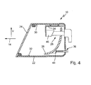
- the Fig. 4 shows an embodiment of a fog lamp 10 with an additional beam aperture 46.
- This radiation diaphragm 46 is arranged relative to the light source 28 such that a radiation emanating directly from the light source 28 is shadowed by the radiation diaphragm 46.
- the radiation diaphragm 46 is configured by its dimensions and arrangement in the housing 22 to shade said radiation such that a reduction in the illumination intensity is comparatively dark compared to a light source located halfway between the upper inner surface 30 and the lower inner surface 32 Area 20 of the light distribution 12 results.
- Such a radiation diaphragm 46 therefore also enables a cost-effective fulfillment of the above-mentioned requirements for a reduced light intensity in the comparatively dark region 20 of the light distribution 12, if shading by the housing 22 is not sufficient. This can be the case, for example, with housings 22 which are not sufficiently deep in the opposite direction to the main emission direction 14 and / or in which requirements on the reflector geometry limit a displacement of the light source 28 at the top.
- the radiation diaphragm 46 may, in principle, be a separate component different from the shield 34. However, an embodiment in which the radiation diaphragm 46 is connected to the shield 34 is preferred, wherein a particularly preferred embodiment is characterized in that the radiation diaphragm forms an integral component with the shield 34.
- the light source 28 preferably has an integrated connection, as it has light sources of the type H11, HB3 or HB4.
- a light source with an integrated connection is understood to mean, in particular, a lamp which already has a seal and an integrated plug connection and thus does not require any further components.
Landscapes
- Engineering & Computer Science (AREA)
- General Engineering & Computer Science (AREA)
- Non-Portable Lighting Devices Or Systems Thereof (AREA)
Abstract
Description
- Die vorliegende Erfindung betrifft einen Nebelscheinwerfer nach dem Oberbegriff des Anspruchs 1. Ein solcher Nebelscheinwerfer ist aus der
DE 198 38 911 A1 bekannt. Der bekannte Nebelscheinwerfer ist dazu eingerichtet, eine Lichtverteilung mit einer Hell-Dunkel-Grenze zu erzeugen, die einen unteren, hellen Bereich der Lichtverteilung von einem oberen, dunklen Bereich der Lichtverteilung trennt, und weist ein Gehäuse, eine das Gehäuse abdeckende, transparente Abdeckscheibe, einen Reflektor und eine Lichtquelle auf. - Die Lichtquelle ist dabei etwa auf halber Höhe der Vertikalausdehnung des Gehäuses im Reflektor angeordnet. Bei dem bekannten Nebelscheinwerfer ist der Lichtquelle des Scheinwerfers eine lichtundurchlässige Strahlenblende zugeordnet, durch die zumindest ein Teil des von der Lichtquelle direkt in Lichtaustrittsrichtung ausgesandten Lichts abgeschirmt wird, um eine sonst mögliche Blendung des Gegenverkehrs zu vermeiden. Eine weitere Funktion der Strahlenblende besteht darin, auch einen Teil des von der Lichtquelle ausgehenden und auf den Reflektor einfallenden Lichts abzuschirmen, um so eine Hell-Dunkel-Grenze des aus dem Scheinwerfer austretenden Lichtbündels zu erzeugen.
- Diese Unterscheidung zwischen den beiden Funktionen der Strahlenblende, nämlich einerseits eine Blendung durch direkt von der Lichtquelle ausgehendes Licht zu verhindern, und andererseits in Verbindung mit dem Reflektor eine Hell-Dunkel-Grenze zu erzeugen, zeigt auf, dass eine Hell-Dunkel-Grenze nicht als scharfe Grenze zwischen einer hohen Lichtintensität im hellen Bereich und einer verschwindenden Lichtintensität im vergleichsweise dunkleren Bereich der Lichtverteilung zu verstehen ist. Es ist vielmehr so, dass auch im vergleichsweise dunkleren Bereich der Lichtverteilung nicht verschwindende Intensitätswerte erlaubt sind.
- Zukünftige Regelungen für eine lichttechnische Homologation von Nebelscheinwerfern sehen jedoch eine Verringerung der oberhalb der Hell-Dunkel-Grenze zulässigen Lichtintensitäts-Werte vor.
- Vor diesem Hintergrund besteht die Aufgabe der Erfindung in der Angabe eines Nebelscheinwerfers, mit dem sich die zukünftigen Anforderungen, die sich auf verringerte Lichtintensitätswerte oberhalb der Hell-Dunkel-Grenze richten, erfüllt werden.
- Diese Aufgabe wird bei einem Nebelscheinwerfer der eingangs genannten Art durch die kennzeichnenden Merkmale des Anspruchs 1 gelöst.
- Der erfindungsgemäße Nebelscheinwerfer zeichnet sich insbesondere dadurch aus, dass die Lichtquelle näher an einer oberen Innenfläche des Gehäuses als an einer unteren Innenfläche des Gehäuses angeordnet ist und dass zwischen der Lichtquelle und der oberen Innenfläche ein flächiges und Wärme verteilendes Schild angeordnet ist.
- Im Vergleich mit dem angegebenen Stand der Technik, der eine zentrale Anordnung der Lichtquelle in dem Reflektor zeigt, wird die erfindungsgemäß näher an der oberen Innenfläche erfolgende Anordnung durch eine Verschiebung der Lichtquelle nach oben erzielt.
- Durch diese Verschiebung nach oben verstärkt sich die abschattende Wirkung, die der obere Teil des Gehäuses auf das direkt von der Lichtquelle nach vorn oben ausgehende Licht ausübt, das in den vergleichsweise dunklen Bereich der Lichtverteilung gestrahlt wird. Die verstärkte Abschattung bewirkt die erwünschte Verringerung der Beleuchtungsintensität im vergleichsweise dunklen Bereich der Lichtverteilung.
- Nachteilig an einer solche Anordnung ist, dass die obere Innenfläche des Gehäuses durch die näher herangerückte Lichtquelle einer erhöhten Wärmestrahlung der Lichtquelle ausgesetzt wird. Das zwischen der Lichtquelle und der oberen Innenfläche angeordnete Schild schützt das Gehäuse vor einer unerwünscht starken Aufheizung, indem es Strahlungswärme aufnimmt und die aufgenommene Wärme über die Schildfläche verteilt.
- Insgesamt wird durch die Erfindung ein einfach aufgebauter, robuster und kostengünstiger Nebelscheinwerfer bereitgestellt, mit dem sich die zukünftigen Homologationsanforderungen erfüllen lassen.
- Eine bevorzugte Ausgestaltung zeichnet sich dadurch aus, dass die Lichtquelle so weit oben angeordnet ist, dass eine direkt von der Lichtquelle ausgehende Strahlung von dem Gehäuse so abgeschattet wird, dass sich im Vergleich zu einer auf halber Höhe zwischen der oberen Innenfläche und der unteren Innenfläche angeordneten Lichtquelle eine Verringerung der Beleuchtungsintensität im vergleichsweise dunklen Bereich der Lichtverteilung ergibt. Auf diese Weise wird das Gehäuse selbst als Lichtbündel-begrenzendes optisches Element verwendet.
- Eine alternative Ausgestaltung sieht eine Strahlenblende vor, die relativ zur Lichtquelle so angeordnet ist, dass eine direkt von der Lichtquelle ausgehende Strahlung von der Strahlenblende so abgeschattet wird, dass sich im Vergleich zu einer auf halber Höhe zwischen der oberen Innenfläche und der unteren Innenfläche angeordneten Lichtquelle eine Verringerung der Beleuchtungsintensität im vergleichsweise dunklen Bereich der Lichtverteilung ergibt. Diese Ausgestaltung erlaubt eine verstärkte Abschattung auch bei Nebelscheinwerfern, bei denen geometrische Bedingungen wie eine unzureichende Tiefe des Gehäuses in Lichtabstrahlrichtung oder Vorgaben an die Reflektorgeometrie verhindern, dass das Gehäuse selbst als ausreichend Lichtbündel-begrenzendes optisches Element wirkt.
- In einem solchen Fall ist besonders bevorzugt, dass die Strahlenblende mit dem Schild verbunden ist. Das hat den Vorteil, dass die Strukturen, die zur Befestigung und definierten Anordnung des Schildes in dem Gehäuse dienen, auch zur Befestigung und definierten Anordnung der Strahlenblende in dem Gehäuse dienen, was zu einem einfachen, robusten und kostengünstigen Aufbau beiträgt.
- Diese Vorteile werden noch verstärkt durch eine Ausgestaltung, bei der die Strahlenblende ein einstückiges Bauteil mit dem Schild bildet.
- Bevorzugt ist auch, dass die Lichtquelle ortsfest im Gehäuse angeordnet ist. Durch eine solche Anordnung ergeben sich definierte und durch die Geometrie der Anordnung festgelegte Abstände und Winkel der Lichtquelle in Bezug auf die abschattenden Elemente des Gehäuses und/oder der mit dem Gehäuse verbundenen Strahlenblende, so dass sich als Folge des Lichtstroms, der von der Lichtquelle ausgeht und der die Lichtaustrittsöffnung ohne vorherige Reflexion am Reflektor passiert, eine definierte und nicht durch Lageänderungen der Lichtquelle beeinflusste Streuung in den vergleichsweise dunklen Bereich der Lichtverteilung ergibt.
- Eine weitere bevorzugte Ausgestaltung zeichnet sich durch eine Verstelleinrichtung zur Einstellung der Hell-Dunkel-Grenze aus, die dazu eingerichtet ist, den Reflektor um eine horizontale Schwenkachse herum zu schwenken. Diese Ausgestaltung erlaubt eine Auf- und Ab-Verstellung der Hell-Dunkel-Grenze ohne Veränderung der Streuwirkung des direkt von der ortsfesten Lichtquelle aus durch den Lichtaustrittsquerschnitt hindurchtretenden Lichtstroms.
- Bevorzugt ist ferner, dass die Verstelleinrichtung dazu eingerichtet ist, den Reflektor um die Lichtquelle herum zu schwenken. Durch diese Ausgestaltung verändern sich in erster Näherung nur Winkel zwischen Lichtquelle und einzelnen Bereichen des Reflektors, die eine vertikale Position der Hell-Dunkel-Grenze und damit der gesamten Lichtverteilung beeinflussen. Abgesehen von dieser gewollten vertikalen Verschiebung ändert sich die Lichtverteilung dagegen in erster Näherung nicht, was für eine von der Vertikal-Einstellung unabhängige Erfüllung der Nebellichtfunktion erwünscht ist.
- Bevorzugt ist auch, dass der Reflektor in Bezug auf die Schwenkachse asymmetrisch ist. Im Vergleich mit einer zentral auf halber Höhe zwischen der unteren und der oberen Innenfläche des Gehäuses angeordneten Lichtquelle muss der nach oben über die Lichtquelle hinaus ragende Teil des Reflektors gekürzt werden, um die höhere Anordnung der Lichtquelle zu erlauben. Die asymmetrische Ausführung des Reflektors erlaubt es, den unterhalb der Lichtquelle liegenden Teil des Reflektors zum Ausgleich zu vergrößern, was eine für die Beleuchtungsintensität wünschenswerte Maximierung der Reflektorfläche erlaubt.
- Aus dem gleichen Grund ist es auch vorteilhaft, dass der Reflektor eine Aussparung, aufweist die so groß ist, dass sie eine Aufnahme der Lichtquelle und eine verschwenkende Relativbewegung zwischen dem Reflektor und der aufgenommenen Lichtquelle erlaubt. Durch eine solche Aussparung bleibt die neben der Aussparung liegende Reflektorfläche erhalten. Besonders bevorzugt ist, dass eine Abmessung der Aussparung längs der Schwenkrichtung größer ist als quer zur Schwenkrichtung, weil dies eine Minimierung der Verluste an Reflektorfläche erlaubt, die zwangsläufig mit einer solchen Aussparung verbunden sind. Eine U-förmige Aussparung hat den Vorteil, durch ihre Öffnung auch eine Verstellbewegung um eine sehr nahe an der oberen Innenfläche des Gehäuses angeordnete Lichtquelle zu erlauben.
- Weitere Vorteile ergeben sich aus den abhängigen Ansprüchen, der Beschreibung und den beigefügten Figuren.
- Es versteht sich, dass die vorstehend genannten und die nachstehend noch zu erläuternden Merkmale nicht nur in der jeweils angegebenen Kombination, sondern auch in anderen Kombinationen oder in Alleinstellung verwendbar sind, ohne den Rahmen der vorliegenden Erfindung zu verlassen.
- Ausführungsbeispiele der Erfindung sind in den Zeichnungen dargestellt und werden in der nachfolgenden Beschreibung näher erläutert. Es zeigen, jeweils in schematischer Form:
- Fig. 1
- einen Nebelscheinwerfer mit einer von dem Nebelscheinwerfer erzeugten Lichtverteilung;
- Fig. 2
- ein Ausführungsbeispiel eines erfindungsgemäßen Nebelscheinwerfers in einer von der Seite betrachteten Schnittdarstellung;
- Fig. 3
- eine Ausgestaltung eines Reflektors des Nebelscheinwerfers aus der
Fig. 2 ,und - Fig. 4
- eine Ausgestaltung eines Nebelscheinwerfers mit einer zusätzlichen Strahlenblende..
- Im Einzelnen zeigt die
Fig. 1 das technische Umfeld der Erfindung in der Gestalt eines Nebelscheinwerfers 10 und einer vom dem Nebelscheinwerfer 10 erzeugten Lichtverteilung 12. Der Nebelscheinwerfer 10 strahlt Licht in eine Hauptabstrahlrichtung 14 ab. Die von dem Nebelscheinwerfer 10 erzeugte Lichtverteilung 12 zeichnet sich dadurch aus, dass sie sich vergleichsweise breit nach rechts und links erstreckt und eine Hell-Dunkel-Grenze 16 aufweist, die einen unteren, vergleichsweise helleren Bereich 18 der Lichtverteilung 12 von einem oberen, vergleichsweise dunkleren Bereich 20 der Lichtverteilung 12 trennt. Dabei liegt die Hell-Dunkel-Grenze 16 in der dargestellten Ausgestaltung unterhalb einer horizontalen Linie H, die eine Vertikale V bei einem Wert Null schneidet, der eine vertikale Lage des Horizonts repräsentiert. Der Nebelscheinwerfer 10 ist dazu eingerichtet, eine solche Lichtverteilung 12 zu erzeugen. - Die
Fig. 2 zeigt ein Ausführungsbeispiel eines erfindungsgemäßen Nebelscheinwerfers 10 in einer von der linken Seite her betrachteten Schnittdarstellung. - Der Nebelscheinwerfer 10 weist ein Gehäuse 22, eine das Gehäuse 22 abdeckende, transparente Abdeckscheibe 24, einen Reflektor 26 und eine Lichtquelle 28 auf. Die Lichtquelle 28 ist in einer bevorzugten Ausgestaltung eine wegen ihrer Einfachheit und wegen ihrer weiten Verbreitung kostengünstige Glühlampe. Der Reflektor 26 ist bevorzugt ein Freiformreflektor, der durch seine Form und Anordnung relativ zu der bevorzugt ortsfest im Gehäuse 22 angeordneten Lichtquelle 28 dazu eingerichtet ist, aus Licht der Lichtquelle 28 eine vorbestimmte Lichtverteilung zu erzeugen, zum Beispiel die Lichtverteilung 12 aus der
Fig. 1 . - Der erfindungsgemäße Nebelscheinwerfer 10 zeichnet sich dadurch aus, dass die Lichtquelle 28 näher an einer oberen Innenfläche 30 des Gehäuses 22 als an einer unteren Innenfläche 32 des Gehäuses 22 angeordnet ist und dass zwischen der Lichtquelle 28 und der oberen Innenfläche 30 ein flächiges, Strahlung reflektierendes und Wärme verteilendes Schild 34 angeordnet ist.
- Im Gegensatz dazu ist die Lichtquelle beim eingangs genannten Stand der Technik etwa auf halber Höhe zwischen einer oberen Innenfläche und einer unteren Innenfläche eines Gehäuses angeordnet. Durch die im Vergleich zum Stand der Technik nach oben verschobene Anordnung der Lichtquelle 28 wird bei dem Nebelscheinwerfer 10 der
Fig. 2 eine Abstrahlung des direkt von der Lichtquelle 28 ausgehenden Lichtes in den Bereich oberhalb der Hell-Dunkel-Grenze 14 durch das Gehäuse 22 vergleichsweise stärker abgeschattet. - Wegen der näher an die obere Innenfläche 30 herangerückten Lichtquelle 28 könnte es ohne Gegenmaßnahmen zu einer unerwünscht hohen Aufheizung des Gehäuses 22 oberhalb der Lichtquelle 28 kommen. Das Schild 34 schützt den darüber liegenden Teil des Gehäuses 22, das in der Regel aus Kunststoff besteht oder Kunststoffanteile aufweist, vor einer solchen Überhitzung durch die Wärmestrahlung der Lichtquelle 28.
- Dadurch kann die Lichtquelle 28 auch bei einer Ausgestaltung als Glühlampe, bei der über 90 % der aufgenommenen elektrischen Leistung als Wärme abgestrahlt wird, weit oben in der Nähe der oberen Innenfläche 30 angeordnet werden, ohne dass hochtemperaturfeste Kunststoffe als Gehäusewerkstoff verwendet werden müssen.
- Für den Schutzzweck ist das Schild 34 in einer bevorzugten Ausgestaltung ein gut wärmeleitendes Metallblech, beispielsweise aus Aluminium. Dies begünstigt eine Verteilung der Strahlungswärme von den Punkten des Schildes 34, die der Lichtquelle 28 am nächsten liegen, über die gesamte Schildfläche. Daraus resultiert eine vergleichsweise gleichmäßige Verteilung der Temperatur über der Schildfläche, was einer unerwünschten Entstehung lokaler Temperaturspitzen an der darüber liegenden oberen Innenfläche 30 entgegenwirkt.
- In einer bevorzugten Ausgestaltung ist die Lichtquelle 28 insbesondere so weit oben angeordnet, dass eine direkt von der Lichtquelle 28 ausgehende Strahlung von dem Gehäuse 22 so abgeschattet wird, dass sich im Vergleich zu einer auf halber Höhe zwischen der oberen Innenfläche 30 und der unteren Innenfläche 32 angeordneten Lichtquelle 28 eine Verringerung der Beleuchtungsintensität im vergleichsweise dunklen Bereich 20 der Lichtverteilung 12 ergibt.
- Zur Einstellung der vertikalen Lage der Hell-Dunkel-Grenze 16 weist der Nebelscheinwerfer 10 eine Verstelleinrichtung 36 auf, die dazu eingerichtet ist, den Reflektor 26 um eine horizontale Schwenkachse herum zu schwenken. In einer einfachen Form besteht die Verstelleinrichtung 36 aus einer Schraube oder Gewindestange 38, die in ein Innengewinde des Gehäuses 22 geschraubt ist und mit ihrer Spitze 40 den Reflektor 26 berührt. Durch Verändern der Einschraubtiefe wird der Reflektor 26 um eine horizontale Schwenkachse herum geschwenkt, die in der Darstellung der
Fig. 2 parallel zur horizontalen Linie H verläuft. Dabei ist bevorzugt, dass die Verstelleinrichtung 36 dazu eingerichtet ist, den Reflektor 26 um die Lichtquelle 28 herum zu schwenken. Die Schraube ist in der dargestellten Ausgestaltung dazu eingerichtet, manuell verstellt zu werden. In einer alternativen Ausgestaltung wird die Verstelleinrichtung von einem Elektromotor angetrieben, der von einem Steuergerät in Abhängigkeit vom Signal eines Neigungssensors angesteuert wird. -
Fig. 3 veranschaulicht eine Ausgestaltung eines Reflektors 26 des Nebelscheinwerfers 10 aus derFig. 2 in einer Vorderansicht, das heißt aus einer der Hauptabstrahlrichtung 14 entgegengesetzten Blickrichtung.Fig. 3 zeigt insbesondere eine horizontal verlaufende Schwenkachse 42, die durch die Lichtquelle 28 hindurch verläuft, so dass eine Einstellung der vertikalen Höhe der Hell-Dunkel-Grenze 16 dadurch erfolgt, dass der Reflektor 26 um die ortsfeste Lichtquelle 28 herum verschwenkt wird. - Die
Fig. 3 zeigt darüber hinaus eine Ausgestaltung, bei der der Reflektor 26 in Bezug auf die Schwenkachse 42 asymmetrisch ist. Die asymmetrische Ausgestaltung erlaubt eine Verlagerung der Lichtquelle 28 nach oben, ohne dafür Einbußen an Reflektorfläche in Kauf nehmen zu müssen. Im Vergleich zu einem bezüglich der Lage der Schwenkachse 42 symmetrischen Reflektor 26 ergibt sich die Asymmetrie gewissermaßen durch ein Verkleinern der oberhalb der Lichtquelle 28 liegenden Reflektorfläche und eine Vergrößerung der unterhalb der Lichtquelle 28 liegenden Reflektorfläche. - Die in der
Fig. 3 dargestellte Ausgestaltung eines Reflektors 26 weist eine Aussparung 44 auf, die so groß ist, dass sie eine Aufnahme der Lichtquelle 28 und eine verschwenkende Relativbewegung zwischen dem Reflektor 26 und der aufgenommenen Lichtquelle 28 erlaubt. Die Aussparung 44 ist bevorzugt so dimensioniert, dass eine Abmessung der Aussparung 44 längs der Schwenkrichtung größer ist als quer zur Schwenkrichtung. Dies ist bei der dargestellten U-förmigen Ausgestaltung der Fall. - Die
Fig. 4 zeigt eine Ausgestaltung eines Nebelscheinwerfers 10 mit einer zusätzlichen Strahlenblende 46. Diese Strahlenblende 46 ist relativ zur Lichtquelle 28 so angeordnet, dass eine direkt von der Lichtquelle 28 ausgehende Strahlung von der Strahlenblende 46 abgeschattet wird. Dabei ist die Strahlenblende 46 durch ihre Abmessungen und Anordnung im Gehäuse 22 dazu eingerichtet, die genannte Strahlung so abzuschatten, dass sich im Vergleich zu einer auf halber Höhe zwischen der oberen Innenfläche 30 und der unteren Innenfläche 32 angeordneten Lichtquelle eine Verringerung der Beleuchtungsintensität im vergleichsweise dunklen Bereich 20 der Lichtverteilung 12 ergibt. - Eine solche Strahlenblende 46 ermöglicht daher auch dann eine kostengünstige Erfüllung der eingangs genannten Forderungen nach einer verringerten Lichtintensität im vergleichsweise dunklen Bereich 20 der Lichtverteilung 12, wenn eine Abschattung durch das Gehäuse 22 nicht ausreicht. Dies kann zum Beispiel bei Gehäusen 22 der Fall sein, die in der Gegenrichtung zur Hauptabstrahlrichtung 14 nicht hinreichend tief sind und/oder bei denen Anforderungen an die Reflektorgeometrie eine Verlagerung der Lichtquelle 28 noch oben begrenzen.
- Die Strahlenblende 46 kann im Prinzip ein separates, vom Schild 34 verschiedenes Bauteil sein. Bevorzugt ist jedoch eine Ausgestaltung, bei der die Strahlenblende 46 mit dem Schild 34 verbunden ist, wobei sich eine besonders bevorzugte Ausgestaltung dadurch auszeichnet, dass die Strahlenblende ein einstückiges Bauteil mit dem Schild 34 bildet.
- Sowohl die Ausgestaltung, die in der
Fig. 2 dargestellt ist, als auch die Ausgestaltung, die in derFig. 4 dargestellt ist, zeichnet sich jeweils durch eine ortsfeste Anordnung der Lichtquelle 28 im Gehäuse 22 aus. Die Lichtquelle 28 weist bevorzugt einen integrierten Anschluss auf, wie ihn Lichtquellen vom Typ H11, HB3 oder HB4 besitzen. Unter einer Lichtquelle mit einem Integrierten Anschluss wird hier insbesondere eine Lampe verstanden, die bereits eine Dichtung und einen integrierten Steckanschluss besitzt und damit keine weiteren Bauteile benötigt.
Claims (12)
- Nebelscheinwerfer (10), der dazu eingerichtet ist, eine Lichtverteilung (12) mit einer Hell-Dunkel-Grenze (16) zu erzeugen, die einen unteren, hellen Bereich (18) der Lichtverteilung (12) von einem oberen, dunklen Bereich (20) der Lichtverteilung (12) trennt, und der ein Gehäuse (22), eine das Gehäuse (22) abdeckende, transparente Abdeckscheibe (24), einen Reflektor (26) und eine Lichtquelle (28) aufweist, dadurch gekennzeichnet, dass die Lichtquelle (28) näher an einer oberen Innenfläche (30) des Gehäuses (22) als an einer unteren Innenfläche (32) des Gehäuses (22) angeordnet ist und dass zwischen der Lichtquelle (28) und der oberen Innenfläche (30) ein flächiges und Wärme verteilendes Schild (34) angeordnet ist.
- Nebelscheinwerfer (10) nach Anspruch 1, dadurch gekennzeichnet, dass die Lichtquelle (28) so weit oben angeordnet ist, dass eine direkt von der Lichtquelle (28) ausgehende Strahlung von dem Gehäuse (22) so abgeschattet wird, dass sich im Vergleich zu einer auf halber Höhe zwischen der oberen Innenfläche und der unteren Innenfläche angeordneten Lichtquelle eine Verringerung der Beleuchtungsintensität im vergleichsweise dunklen Bereich (20) der Lichtverteilung (12) ergibt.
- Nebelscheinwerfer (10) nach Anspruch 1, dadurch gekennzeichnet, dass eine Strahlenblende (46) relativ zur Lichtquelle (28) so angeordnet ist, dass eine direkt von der Lichtquelle (28) ausgehende Strahlung von der Strahlenblende (46) so abgeschattet wird, dass sich im Vergleich zu einer auf halber Höhe zwischen der oberen Innenfläche und der unteren Innenfläche angeordneten Lichtquelle eine Verringerung der Beleuchtungsintensität im vergleichsweise dunklen Bereich (20) der Lichtverteilung (12) ergibt.
- Nebelscheinwerfer (10) nach Anspruch 3, dadurch gekennzeichnet, dass die Strahlenblende (46) mit dem Schild (34) verbunden ist.
- Nebelscheinwerfer (10) nach Anspruch 4, dadurch gekennzeichnet, dass die Strahlenblende (46) ein einstückiges Bauteil mit dem Schild (34) bildet.
- Nebelscheinwerfer (10) nach einem der vorhergehenden Ansprüche, dadurch gekennzeichnet, dass die Lichtquelle (28) ortsfest im Gehäuse (22) angeordnet ist
- Nebelscheinwerfer (10) nach einem der vorhergehenden Ansprüche, dadurch gekennzeichnet, dass er eine Verstelleinrichtung (36) zur Einstellung der vertikalen Lage der Hell-Dunkel-Grenze (16) aufweist, die dazu eingerichtet ist, den Reflektor (26) um eine horizontale Schwenkachse (42) herum zu schwenken.
- Nebelscheinwerfer (10) nach Anspruch 7, dadurch gekennzeichnet, dass die Verstelleinrichtung (36) dazu eingerichtet ist, den Reflektor (26) um die Lichtquelle (28) herum zu schwenken.
- Nebelscheinwerfer (10) nach Anspruch 7 oder 8, dadurch gekennzeichnet, dass der Reflektor (26) in Bezug auf die Schwenkachse (42) asymmetrisch ist.
- Nebelscheinwerfer (10) nach einem der vorhergehenden Ansprüche, dadurch gekennzeichnet, dass der Reflektor (26) eine Aussparung (44) aufweist die so groß ist, dass sie eine Aufnahme der Lichtquelle (28) und eine verschwenkende Relativbewegung zwischen dem Reflektor (26) und der aufgenommenen Lichtquelle (28) erlaubt.
- Nebelscheinwerfer (10) nach Anspruch 10, dadurch gekennzeichnet, dass eine Abmessung der Aussparung (44) längs der Schwenkrichtung größer ist als quer zur Schwenkrichtung.
- Nebelscheinwerfer (10) nach Anspruch 11, dadurch gekennzeichnet, dass die Aussparung (44) U-förmig ist.
Applications Claiming Priority (1)
| Application Number | Priority Date | Filing Date | Title |
|---|---|---|---|
| DE102010005387A DE102010005387A1 (de) | 2010-01-22 | 2010-01-22 | Kostengünstiger Nebelscheinwerfer |
Publications (2)
| Publication Number | Publication Date |
|---|---|
| EP2354649A1 true EP2354649A1 (de) | 2011-08-10 |
| EP2354649B1 EP2354649B1 (de) | 2014-07-23 |
Family
ID=43825318
Family Applications (1)
| Application Number | Title | Priority Date | Filing Date |
|---|---|---|---|
| EP11000061.9A Not-in-force EP2354649B1 (de) | 2010-01-22 | 2011-01-05 | Kostengünstiger Nebelscheinwerfer |
Country Status (2)
| Country | Link |
|---|---|
| EP (1) | EP2354649B1 (de) |
| DE (1) | DE102010005387A1 (de) |
Cited By (1)
| Publication number | Priority date | Publication date | Assignee | Title |
|---|---|---|---|---|
| WO2014149006A1 (en) * | 2013-03-18 | 2014-09-25 | Hella Saturnus Slovenija, Proizvodnja Svetlobne Opreme Za Motorna In Druga Vozila, D.O.O. | Motor vehicle light, in particular a front light or a fog light with integrated tubular heat conductive member |
Citations (5)
| Publication number | Priority date | Publication date | Assignee | Title |
|---|---|---|---|---|
| US4555748A (en) * | 1982-10-28 | 1985-11-26 | General Electric Company | Truncated motor vehicle headlamp |
| FR2704934A1 (fr) * | 1993-05-04 | 1994-11-10 | Valeo Vision | Projecteur de véhicule automobile équipé d'un moyen formant radiateur et d'un élément d'occultation ou de traitement de lumière. |
| US5477440A (en) * | 1993-04-28 | 1995-12-19 | Valeo Vision | Low-dazzle headlamp for a motor vehicle |
| DE19838911A1 (de) | 1998-08-27 | 2000-03-30 | Bosch Gmbh Robert | Beleuchtungseinrichtung für Fahrzeuge |
| US6746143B1 (en) * | 2003-03-27 | 2004-06-08 | Guide Corporation | Variable progressive beam headlamp |
-
2010
- 2010-01-22 DE DE102010005387A patent/DE102010005387A1/de not_active Withdrawn
-
2011
- 2011-01-05 EP EP11000061.9A patent/EP2354649B1/de not_active Not-in-force
Patent Citations (5)
| Publication number | Priority date | Publication date | Assignee | Title |
|---|---|---|---|---|
| US4555748A (en) * | 1982-10-28 | 1985-11-26 | General Electric Company | Truncated motor vehicle headlamp |
| US5477440A (en) * | 1993-04-28 | 1995-12-19 | Valeo Vision | Low-dazzle headlamp for a motor vehicle |
| FR2704934A1 (fr) * | 1993-05-04 | 1994-11-10 | Valeo Vision | Projecteur de véhicule automobile équipé d'un moyen formant radiateur et d'un élément d'occultation ou de traitement de lumière. |
| DE19838911A1 (de) | 1998-08-27 | 2000-03-30 | Bosch Gmbh Robert | Beleuchtungseinrichtung für Fahrzeuge |
| US6746143B1 (en) * | 2003-03-27 | 2004-06-08 | Guide Corporation | Variable progressive beam headlamp |
Cited By (1)
| Publication number | Priority date | Publication date | Assignee | Title |
|---|---|---|---|---|
| WO2014149006A1 (en) * | 2013-03-18 | 2014-09-25 | Hella Saturnus Slovenija, Proizvodnja Svetlobne Opreme Za Motorna In Druga Vozila, D.O.O. | Motor vehicle light, in particular a front light or a fog light with integrated tubular heat conductive member |
Also Published As
| Publication number | Publication date |
|---|---|
| EP2354649B1 (de) | 2014-07-23 |
| DE102010005387A1 (de) | 2011-07-28 |
Similar Documents
| Publication | Publication Date | Title |
|---|---|---|
| DE102013214116B4 (de) | Scheinwerfer für ein blendungsfreies Fernlicht | |
| DE102006034353B4 (de) | Fahrzeugleuchte | |
| EP2339228B1 (de) | Lichtmodul für eine Beleuchtungseinrichtung sowie Beleuchtungseinrichtung eines Kraftfahrzeugs mit einem solchen Lichtmodul | |
| DE102006061751B4 (de) | Fahrzeugscheinwerfer | |
| EP2420728B1 (de) | Projektionsscheinwerfer mit gezielt abgeschwächtem Lichtintensitätsgradienten an der Hell-Dunkel-Grenze | |
| EP2503225B1 (de) | Kraftfahrzeugbeleuchtungseinrichtung und Kraftfahrzeugscheinwerfer mit einer solchen Beleuchtungseinrichtung | |
| DE102007040728B4 (de) | Fahrzeugscheinwerfer | |
| DE102014107130B4 (de) | Beleuchtungssystem | |
| DE102017204517A1 (de) | Optisches Projektionssystem und Projektionsscheinwerfer zur Bildung eines zweifachen Lichtwegs und Fahrzeug, in dem dieses optische System eingesetzt wrid | |
| DE102010009640A1 (de) | Frontscheinwerfer mit einem LED-Reflexionssystem mit Nebellicht- und Tagfahrlichtfunktion | |
| DE112019004392B4 (de) | Abblendlicht-III-Zonen-Beleuchtungsmodul, Fahrzeug-Scheinwerfer und Fahrzeug | |
| DE60120263T2 (de) | Fahrzeugscheinwerfer mit einem rohrähnlichen Lampenelement | |
| DE102018120733B4 (de) | Beleuchtungseinrichtung einer Fahrzeugleuchte, Fahrzeugleuchten-Baugruppe und Fahrzeug | |
| DE102011003814A1 (de) | Lichtmodul eines Kraftfahrzeugscheinwerfers | |
| EP2354649B1 (de) | Kostengünstiger Nebelscheinwerfer | |
| DE102004014900B4 (de) | Fahrzeug-Scheinwerfereinrichtung | |
| AT500750A4 (de) | Fahrzeugscheinwerfer | |
| DE102019209129A1 (de) | Scheinwerfer für ein Fahrzeug | |
| DE102014110702B4 (de) | Abschirmvorrichtung für Abblendlicht-Scheinwerfer | |
| DE102013202370B4 (de) | Lichtmodul für ein Kraftfahrzeug | |
| DE19832466A1 (de) | Scheinwerferanordnung nach dem Profjektionstyp für ein Kraftfahrzeug | |
| DE2856448C3 (de) | Abblendscheinwerfer für Fahrzeuge | |
| DE102011102679B4 (de) | Leuchteinheit für einen Scheinwerfer eines Fahrzeugs | |
| DE102021100513B3 (de) | Reflektor für eine Leuchte | |
| DE102019112482A1 (de) | Motorradleuchte |
Legal Events
| Date | Code | Title | Description |
|---|---|---|---|
| PUAI | Public reference made under article 153(3) epc to a published international application that has entered the european phase |
Free format text: ORIGINAL CODE: 0009012 |
|
| AK | Designated contracting states |
Kind code of ref document: A1 Designated state(s): AL AT BE BG CH CY CZ DE DK EE ES FI FR GB GR HR HU IE IS IT LI LT LU LV MC MK MT NL NO PL PT RO RS SE SI SK SM TR |
|
| AX | Request for extension of the european patent |
Extension state: BA ME |
|
| 17P | Request for examination filed |
Effective date: 20120120 |
|
| GRAP | Despatch of communication of intention to grant a patent |
Free format text: ORIGINAL CODE: EPIDOSNIGR1 |
|
| INTG | Intention to grant announced |
Effective date: 20140212 |
|
| GRAS | Grant fee paid |
Free format text: ORIGINAL CODE: EPIDOSNIGR3 |
|
| GRAA | (expected) grant |
Free format text: ORIGINAL CODE: 0009210 |
|
| AK | Designated contracting states |
Kind code of ref document: B1 Designated state(s): AL AT BE BG CH CY CZ DE DK EE ES FI FR GB GR HR HU IE IS IT LI LT LU LV MC MK MT NL NO PL PT RO RS SE SI SK SM TR |
|
| REG | Reference to a national code |
Ref country code: GB Ref legal event code: FG4D Free format text: NOT ENGLISH |
|
| REG | Reference to a national code |
Ref country code: CH Ref legal event code: EP |
|
| REG | Reference to a national code |
Ref country code: IE Ref legal event code: FG4D Free format text: LANGUAGE OF EP DOCUMENT: GERMAN |
|
| REG | Reference to a national code |
Ref country code: AT Ref legal event code: REF Ref document number: 679084 Country of ref document: AT Kind code of ref document: T Effective date: 20140815 |
|
| REG | Reference to a national code |
Ref country code: DE Ref legal event code: R096 Ref document number: 502011003804 Country of ref document: DE Effective date: 20140911 |
|
| REG | Reference to a national code |
Ref country code: NL Ref legal event code: VDEP Effective date: 20140723 |
|
| REG | Reference to a national code |
Ref country code: LT Ref legal event code: MG4D |
|
| PG25 | Lapsed in a contracting state [announced via postgrant information from national office to epo] |
Ref country code: NO Free format text: LAPSE BECAUSE OF FAILURE TO SUBMIT A TRANSLATION OF THE DESCRIPTION OR TO PAY THE FEE WITHIN THE PRESCRIBED TIME-LIMIT Effective date: 20141023 Ref country code: FI Free format text: LAPSE BECAUSE OF FAILURE TO SUBMIT A TRANSLATION OF THE DESCRIPTION OR TO PAY THE FEE WITHIN THE PRESCRIBED TIME-LIMIT Effective date: 20140723 Ref country code: LT Free format text: LAPSE BECAUSE OF FAILURE TO SUBMIT A TRANSLATION OF THE DESCRIPTION OR TO PAY THE FEE WITHIN THE PRESCRIBED TIME-LIMIT Effective date: 20140723 Ref country code: BG Free format text: LAPSE BECAUSE OF FAILURE TO SUBMIT A TRANSLATION OF THE DESCRIPTION OR TO PAY THE FEE WITHIN THE PRESCRIBED TIME-LIMIT Effective date: 20141023 Ref country code: GR Free format text: LAPSE BECAUSE OF FAILURE TO SUBMIT A TRANSLATION OF THE DESCRIPTION OR TO PAY THE FEE WITHIN THE PRESCRIBED TIME-LIMIT Effective date: 20141024 Ref country code: SE Free format text: LAPSE BECAUSE OF FAILURE TO SUBMIT A TRANSLATION OF THE DESCRIPTION OR TO PAY THE FEE WITHIN THE PRESCRIBED TIME-LIMIT Effective date: 20140723 Ref country code: ES Free format text: LAPSE BECAUSE OF FAILURE TO SUBMIT A TRANSLATION OF THE DESCRIPTION OR TO PAY THE FEE WITHIN THE PRESCRIBED TIME-LIMIT Effective date: 20140723 Ref country code: PT Free format text: LAPSE BECAUSE OF FAILURE TO SUBMIT A TRANSLATION OF THE DESCRIPTION OR TO PAY THE FEE WITHIN THE PRESCRIBED TIME-LIMIT Effective date: 20141124 |
|
| PG25 | Lapsed in a contracting state [announced via postgrant information from national office to epo] |
Ref country code: IS Free format text: LAPSE BECAUSE OF FAILURE TO SUBMIT A TRANSLATION OF THE DESCRIPTION OR TO PAY THE FEE WITHIN THE PRESCRIBED TIME-LIMIT Effective date: 20141123 Ref country code: HR Free format text: LAPSE BECAUSE OF FAILURE TO SUBMIT A TRANSLATION OF THE DESCRIPTION OR TO PAY THE FEE WITHIN THE PRESCRIBED TIME-LIMIT Effective date: 20140723 Ref country code: CY Free format text: LAPSE BECAUSE OF FAILURE TO SUBMIT A TRANSLATION OF THE DESCRIPTION OR TO PAY THE FEE WITHIN THE PRESCRIBED TIME-LIMIT Effective date: 20140723 Ref country code: RS Free format text: LAPSE BECAUSE OF FAILURE TO SUBMIT A TRANSLATION OF THE DESCRIPTION OR TO PAY THE FEE WITHIN THE PRESCRIBED TIME-LIMIT Effective date: 20140723 Ref country code: NL Free format text: LAPSE BECAUSE OF FAILURE TO SUBMIT A TRANSLATION OF THE DESCRIPTION OR TO PAY THE FEE WITHIN THE PRESCRIBED TIME-LIMIT Effective date: 20140723 Ref country code: LV Free format text: LAPSE BECAUSE OF FAILURE TO SUBMIT A TRANSLATION OF THE DESCRIPTION OR TO PAY THE FEE WITHIN THE PRESCRIBED TIME-LIMIT Effective date: 20140723 Ref country code: PL Free format text: LAPSE BECAUSE OF FAILURE TO SUBMIT A TRANSLATION OF THE DESCRIPTION OR TO PAY THE FEE WITHIN THE PRESCRIBED TIME-LIMIT Effective date: 20140723 |
|
| REG | Reference to a national code |
Ref country code: DE Ref legal event code: R026 Ref document number: 502011003804 Country of ref document: DE |
|
| PG25 | Lapsed in a contracting state [announced via postgrant information from national office to epo] |
Ref country code: CZ Free format text: LAPSE BECAUSE OF FAILURE TO SUBMIT A TRANSLATION OF THE DESCRIPTION OR TO PAY THE FEE WITHIN THE PRESCRIBED TIME-LIMIT Effective date: 20140723 Ref country code: RO Free format text: LAPSE BECAUSE OF FAILURE TO SUBMIT A TRANSLATION OF THE DESCRIPTION OR TO PAY THE FEE WITHIN THE PRESCRIBED TIME-LIMIT Effective date: 20140723 Ref country code: DK Free format text: LAPSE BECAUSE OF FAILURE TO SUBMIT A TRANSLATION OF THE DESCRIPTION OR TO PAY THE FEE WITHIN THE PRESCRIBED TIME-LIMIT Effective date: 20140723 Ref country code: EE Free format text: LAPSE BECAUSE OF FAILURE TO SUBMIT A TRANSLATION OF THE DESCRIPTION OR TO PAY THE FEE WITHIN THE PRESCRIBED TIME-LIMIT Effective date: 20140723 Ref country code: SK Free format text: LAPSE BECAUSE OF FAILURE TO SUBMIT A TRANSLATION OF THE DESCRIPTION OR TO PAY THE FEE WITHIN THE PRESCRIBED TIME-LIMIT Effective date: 20140723 Ref country code: IT Free format text: LAPSE BECAUSE OF FAILURE TO SUBMIT A TRANSLATION OF THE DESCRIPTION OR TO PAY THE FEE WITHIN THE PRESCRIBED TIME-LIMIT Effective date: 20140723 |
|
| PLBI | Opposition filed |
Free format text: ORIGINAL CODE: 0009260 |
|
| PLAX | Notice of opposition and request to file observation + time limit sent |
Free format text: ORIGINAL CODE: EPIDOSNOBS2 |
|
| 26 | Opposition filed |
Opponent name: VALEO VISION SAS Effective date: 20150423 |
|
| PG25 | Lapsed in a contracting state [announced via postgrant information from national office to epo] |
Ref country code: BE Free format text: LAPSE BECAUSE OF NON-PAYMENT OF DUE FEES Effective date: 20150131 |
|
| REG | Reference to a national code |
Ref country code: CH Ref legal event code: PL |
|
| PG25 | Lapsed in a contracting state [announced via postgrant information from national office to epo] |
Ref country code: LU Free format text: LAPSE BECAUSE OF FAILURE TO SUBMIT A TRANSLATION OF THE DESCRIPTION OR TO PAY THE FEE WITHIN THE PRESCRIBED TIME-LIMIT Effective date: 20150105 |
|
| GBPC | Gb: european patent ceased through non-payment of renewal fee |
Effective date: 20150105 |
|
| PG25 | Lapsed in a contracting state [announced via postgrant information from national office to epo] |
Ref country code: MC Free format text: LAPSE BECAUSE OF FAILURE TO SUBMIT A TRANSLATION OF THE DESCRIPTION OR TO PAY THE FEE WITHIN THE PRESCRIBED TIME-LIMIT Effective date: 20140723 |
|
| PLAF | Information modified related to communication of a notice of opposition and request to file observations + time limit |
Free format text: ORIGINAL CODE: EPIDOSCOBS2 |
|
| PG25 | Lapsed in a contracting state [announced via postgrant information from national office to epo] |
Ref country code: GB Free format text: LAPSE BECAUSE OF NON-PAYMENT OF DUE FEES Effective date: 20150105 Ref country code: LI Free format text: LAPSE BECAUSE OF NON-PAYMENT OF DUE FEES Effective date: 20150131 Ref country code: CH Free format text: LAPSE BECAUSE OF NON-PAYMENT OF DUE FEES Effective date: 20150131 |
|
| REG | Reference to a national code |
Ref country code: IE Ref legal event code: MM4A |
|
| PG25 | Lapsed in a contracting state [announced via postgrant information from national office to epo] |
Ref country code: SI Free format text: LAPSE BECAUSE OF FAILURE TO SUBMIT A TRANSLATION OF THE DESCRIPTION OR TO PAY THE FEE WITHIN THE PRESCRIBED TIME-LIMIT Effective date: 20140723 |
|
| PLBB | Reply of patent proprietor to notice(s) of opposition received |
Free format text: ORIGINAL CODE: EPIDOSNOBS3 |
|
| REG | Reference to a national code |
Ref country code: FR Ref legal event code: PLFP Year of fee payment: 6 |
|
| PG25 | Lapsed in a contracting state [announced via postgrant information from national office to epo] |
Ref country code: IE Free format text: LAPSE BECAUSE OF NON-PAYMENT OF DUE FEES Effective date: 20150105 |
|
| REG | Reference to a national code |
Ref country code: FR Ref legal event code: PLFP Year of fee payment: 7 |
|
| PG25 | Lapsed in a contracting state [announced via postgrant information from national office to epo] |
Ref country code: MT Free format text: LAPSE BECAUSE OF FAILURE TO SUBMIT A TRANSLATION OF THE DESCRIPTION OR TO PAY THE FEE WITHIN THE PRESCRIBED TIME-LIMIT Effective date: 20140723 |
|
| REG | Reference to a national code |
Ref country code: AT Ref legal event code: MM01 Ref document number: 679084 Country of ref document: AT Kind code of ref document: T Effective date: 20160105 |
|
| PLAB | Opposition data, opponent's data or that of the opponent's representative modified |
Free format text: ORIGINAL CODE: 0009299OPPO |
|
| R26 | Opposition filed (corrected) |
Opponent name: VALEO VISION SAS Effective date: 20150423 |
|
| PG25 | Lapsed in a contracting state [announced via postgrant information from national office to epo] |
Ref country code: HU Free format text: LAPSE BECAUSE OF FAILURE TO SUBMIT A TRANSLATION OF THE DESCRIPTION OR TO PAY THE FEE WITHIN THE PRESCRIBED TIME-LIMIT; INVALID AB INITIO Effective date: 20110105 Ref country code: AT Free format text: LAPSE BECAUSE OF NON-PAYMENT OF DUE FEES Effective date: 20160105 Ref country code: SM Free format text: LAPSE BECAUSE OF FAILURE TO SUBMIT A TRANSLATION OF THE DESCRIPTION OR TO PAY THE FEE WITHIN THE PRESCRIBED TIME-LIMIT Effective date: 20140723 |
|
| PLCK | Communication despatched that opposition was rejected |
Free format text: ORIGINAL CODE: EPIDOSNREJ1 |
|
| REG | Reference to a national code |
Ref country code: DE Ref legal event code: R100 Ref document number: 502011003804 Country of ref document: DE |
|
| PG25 | Lapsed in a contracting state [announced via postgrant information from national office to epo] |
Ref country code: TR Free format text: LAPSE BECAUSE OF FAILURE TO SUBMIT A TRANSLATION OF THE DESCRIPTION OR TO PAY THE FEE WITHIN THE PRESCRIBED TIME-LIMIT Effective date: 20140723 |
|
| PLBN | Opposition rejected |
Free format text: ORIGINAL CODE: 0009273 |
|
| STAA | Information on the status of an ep patent application or granted ep patent |
Free format text: STATUS: OPPOSITION REJECTED |
|
| 27O | Opposition rejected |
Effective date: 20170624 |
|
| REG | Reference to a national code |
Ref country code: FR Ref legal event code: PLFP Year of fee payment: 8 |
|
| PG25 | Lapsed in a contracting state [announced via postgrant information from national office to epo] |
Ref country code: MK Free format text: LAPSE BECAUSE OF FAILURE TO SUBMIT A TRANSLATION OF THE DESCRIPTION OR TO PAY THE FEE WITHIN THE PRESCRIBED TIME-LIMIT Effective date: 20140723 |
|
| PG25 | Lapsed in a contracting state [announced via postgrant information from national office to epo] |
Ref country code: AL Free format text: LAPSE BECAUSE OF FAILURE TO SUBMIT A TRANSLATION OF THE DESCRIPTION OR TO PAY THE FEE WITHIN THE PRESCRIBED TIME-LIMIT Effective date: 20140723 |
|
| PGFP | Annual fee paid to national office [announced via postgrant information from national office to epo] |
Ref country code: FR Payment date: 20181220 Year of fee payment: 9 |
|
| PGFP | Annual fee paid to national office [announced via postgrant information from national office to epo] |
Ref country code: DE Payment date: 20191218 Year of fee payment: 10 |
|
| PG25 | Lapsed in a contracting state [announced via postgrant information from national office to epo] |
Ref country code: FR Free format text: LAPSE BECAUSE OF NON-PAYMENT OF DUE FEES Effective date: 20200131 |
|
| REG | Reference to a national code |
Ref country code: DE Ref legal event code: R119 Ref document number: 502011003804 Country of ref document: DE |
|
| PG25 | Lapsed in a contracting state [announced via postgrant information from national office to epo] |
Ref country code: DE Free format text: LAPSE BECAUSE OF NON-PAYMENT OF DUE FEES Effective date: 20210803 |