EP2354005A2 - Systeme und Verfahren zur Steuerung der Strukturkonturen - Google Patents
Systeme und Verfahren zur Steuerung der Strukturkonturen Download PDFInfo
- Publication number
- EP2354005A2 EP2354005A2 EP11152746A EP11152746A EP2354005A2 EP 2354005 A2 EP2354005 A2 EP 2354005A2 EP 11152746 A EP11152746 A EP 11152746A EP 11152746 A EP11152746 A EP 11152746A EP 2354005 A2 EP2354005 A2 EP 2354005A2
- Authority
- EP
- European Patent Office
- Prior art keywords
- contour
- force
- control system
- data
- control module
- Prior art date
- Legal status (The legal status is an assumption and is not a legal conclusion. Google has not performed a legal analysis and makes no representation as to the accuracy of the status listed.)
- Granted
Links
Images


Classifications
-
- B—PERFORMING OPERATIONS; TRANSPORTING
- B64—AIRCRAFT; AVIATION; COSMONAUTICS
- B64F—GROUND OR AIRCRAFT-CARRIER-DECK INSTALLATIONS SPECIALLY ADAPTED FOR USE IN CONNECTION WITH AIRCRAFT; DESIGNING, MANUFACTURING, ASSEMBLING, CLEANING, MAINTAINING OR REPAIRING AIRCRAFT, NOT OTHERWISE PROVIDED FOR; HANDLING, TRANSPORTING, TESTING OR INSPECTING AIRCRAFT COMPONENTS, NOT OTHERWISE PROVIDED FOR
- B64F5/00—Designing, manufacturing, assembling, cleaning, maintaining or repairing aircraft, not otherwise provided for; Handling, transporting, testing or inspecting aircraft components, not otherwise provided for
- B64F5/60—Testing or inspecting aircraft components or systems
-
- Y—GENERAL TAGGING OF NEW TECHNOLOGICAL DEVELOPMENTS; GENERAL TAGGING OF CROSS-SECTIONAL TECHNOLOGIES SPANNING OVER SEVERAL SECTIONS OF THE IPC; TECHNICAL SUBJECTS COVERED BY FORMER USPC CROSS-REFERENCE ART COLLECTIONS [XRACs] AND DIGESTS
- Y02—TECHNOLOGIES OR APPLICATIONS FOR MITIGATION OR ADAPTATION AGAINST CLIMATE CHANGE
- Y02P—CLIMATE CHANGE MITIGATION TECHNOLOGIES IN THE PRODUCTION OR PROCESSING OF GOODS
- Y02P90/00—Enabling technologies with a potential contribution to greenhouse gas [GHG] emissions mitigation
- Y02P90/02—Total factory control, e.g. smart factories, flexible manufacturing systems [FMS] or integrated manufacturing systems [IMS]
Definitions
- the present disclosure relates generally to structure control and, more particularly, to applying, monitoring, and adjusting forces to a structure to control structure contours.
- a structure may include stresses induced during manufacturing that alter the shape of the structure, even after manufacturing of the structure is completed. Externally, the structure may be subjected to minor or even significant changes induced by movement, shifts in the earth, transportation forces, damage, other, or other forces.
- a structure may be initially formed at one facility, and may then pass to or through a number of other facilities.
- the structure must be transported large distances, even between multiple continents, between the time the first manufacturing process is performed on the structure and the time at which the structure is a part of, or is itself, a finished product.
- the transportation of the structure often introduces new forces to the structure, possibly resulting in deformation of the structure.
- a first manufacturing facility may be aware of certain structure characteristics of which a second manufacturing facility is unaware. Thus, a second facility may undertake steps to collect data already collected at a first facility.
- Systems and methods described herein provide for the determination of the contours of a structure, an analysis of the contours and/or comparison of the contours to a desired design and associated tolerances, and the controlled application and management of forces to the structure for precision assembly, machining, and/or manufacturing. Additionally, the contours of the structure may be controlled during transportation to detect, and in some instances correct, deformation of the structure during transportation.
- the embodiments disclosed herein provide for a contour control system that includes contour measurement modules and force control modules to measure contours of a structure. In addition to inputting data to the contour control system, the force control modules can be controlled by the contour control system and/or a control system thereof. The control system is operative to determine what forces, if any, should be applied to a structure to obtain the desired contours.
- the control system also is operative to control the force control modules to apply the determined forces, and to monitor the applied forces to ensure that the forces remain within acceptable limits. If internal or external factors result in any change in the structure and/or the forces sensed by or applied by the contour control system, the contour control system is able to compensate for these changes by adjusting the amount of force applied by the force control modules. In this manner, the embodiments described herein allow for continuous structure contour monitoring and control.
- a contour control system for controlling a contour of a structure.
- the system includes a force control module operative to apply a force to the structure, and a control system communicatively linked to the force control module.
- the control system includes a processor functionally coupled to a memory.
- the memory includes computer-readable instructions executable by the processor to make the contour control system operative to obtain actual contour data indicating the configuration and location of the contour, and to receive target contour data associated with a desired structure.
- the target contour data includes data indicating a desired location and configuration of the contour, and a pre-defined tolerance associated with the desired location and configuration of the contour.
- the memory further includes computer-readable instructions executable by the processor to make the contour control system further operative to analyze the actual contour data and the target contour data to determine if the location and configuration of the contour are within the pre-defined tolerance of the desired location and configuration of the contour, and to determine a force to be applied by the force control module to control the location and configuration of the contour.
- a method for controlling a contour of a structure includes obtaining, with a measurement device, actual contour data.
- the actual contour data indicates at least one of a configuration of the contour and a location of the contour.
- the method further includes receiving, at a contour control system, target contour data associated with a desired structure.
- the target contour data includes data indicating at least one of a desired location of a contour, and a desired configuration of the contour. Additionally, the target contour data includes a tolerance associated with the contour.
- the method also includes analyzing the actual contour data and the target contour data to determine if the contour is consistent with the target contour data, and determining a force to be applied by a force control module to control the at least one of the location of the contour and the configuration of the contour.
- the method also includes activating the force control module to apply the determined force to the structure to control the at least one of the location of the contour and the configuration of the contour, and monitoring the structure to determine if an additional force should be applied to control the at least one of the location of the contour and the configuration of the contour.
- a method for controlling a contour of a structure includes receiving, at a contour control system, stored load data associated with the structure.
- the stored load data indicates a force applied to the structure by a force application device to control the contour, and a tolerance associated with the force.
- the method further includes obtaining, using a force sensor of a force control module, a structure load data indicating a force between the structure and the force control module.
- the method also includes analyzing the structure load data and the stored load data to determine if the structure load data is consistent with the stored load data and the tolerance, and determining a force to be applied by a force control module to match the stored load data and the tolerance.
- the method includes activating the force control module to apply the determined force to the structure, and monitoring the structure to determine if an additional force should be applied to the structure.
- the contours of the structure are controlled during manufacturing, machining, assembly, and/or transportation.
- the embodiments described below provide a contour control system capable of using contour measurement devices to determine the contours of a structure, compare the structure contours with target contour data associated with a desired structure, and use a system of force control modules and support structures to apply forces to the structure to control the contours of the structure.
- the contour control system includes, in some embodiments, a control system operative to monitor and control the forces applied to the structure by the force control modules and/or support structures.
- precise forces may be applied to the structure at various locations to control the contours of the structure at a desired time, for example, during manufacturing and/or assembly of the structure.
- the contour control system is operative to continuously monitor and adjust the contours of the structure, thereby ensuring that the structure contours are maintained at or near an optimal configuration during manufacturing, transportation, assembly, or other operations, during which internal or external forces might otherwise shift the structure contours out of the desired configurations.
- the forces applied by the force control modules are continuously monitored and adjusted to ensure that structural and/or material constraints are not exceeded and/or to prevent undesirable material and/or structure deformation.
- FIGURE 1 shows a contour control system 100, according to an exemplary embodiment of the present disclosure.
- the contour control system 100 includes a control system 102 that is communicatively linked to one or more force control modules 104 ("FCM's"), each of which is configured to apply a force to support, level, deform, manipulate, and/or otherwise control the contours of a structure 106.
- FCM's force control modules 104
- control system 102 also is communicatively linked to one or more contour measurement modules 108 ("CMM's"), each of which is configured to measure the contours of the structure 106.
- CMS's contour measurement modules 108
- the FCM's 104 include one or more air cushion contact pads configured to selectively apply a force to the structure 106.
- the air cushion pads can be inflated to increase pressure within the air cushion pads, thereby applying a force to surfaces or points of the structure 106 in contact with the air cushion pads.
- the air cushion pads can be deflated to decrease pressure within the air cushion pads, thereby reducing forces applied to the surfaces or points of the structure 106 in contact with air cushion pads.
- Suitable examples of the air cushion pads include, but are not limited to, various air load modules sold by AeroGo of Seattle, WA under the mark AEROGO LOAD MODULETM. It should be understood that air cushion pads and/or air load modules can be configured as flat pads, or can be molded to match or approximate a particular surface.
- the FCM's 104 include one or more vacuum cups configured to selectively apply a force to the structure 106.
- the vacuum cups can be activated to increase negative pressure inside the vacuum cups at surfaces or points of the structure 106 in contact with the vacuum cups, thereby generating pulling forces at the surfaces or points of the structure 106.
- the vacuum cups can be deactivated to decrease the negative pressure inside the vacuum cups, thereby reducing pulling forces at the surfaces or points of the structure 106.
- Suitable examples of the vacuum cups include, but are not limited to, various vacuum cups sold by Anver Corp. of Hudson, MA under the mark ANVER®, including model numbers VC119Q-GR and VC125Q-2-GR.
- the FCM's 104 include one or more structure support cradles configured to support the structure 106, thereby applying static forces to the surfaces or points of the structure 106.
- the structure support cradle is equipped with and/or complimented by one or more air cushion contact pads and/or vacuum cups.
- the contour control system 100 may include air compressors, pressure sensors, air flow regulators, vacuum pumps, air lines, vacuum lines, and power supplies to operate and/or control the various components of the contour control system 100, including the FCM's 104 and structure support cradles and/or components thereof.
- the structure 106 may be any part, tool, or other structure that requires leveling and/or machining, and is not limited to an airplane fuselage or other aerospace structure.
- the CMM's 108 include one or more measurement devices configured to measure the location of and/or a configuration of one or more surfaces, surface contours, and/or surface points of the structure 106.
- the CMM's 108 include contactless measuring devices such as, for example, a laser radar or laser tracking device.
- Suitable examples of a CMM 108 include, but are not limited to, high-speed contactless laser scanners sold by Leica Geosystems, part of the Hexagon Group of Sweden, for example a high speed laser tracker sold under the mark LEICA ABSOLUTE TRACKERTM, and laser radar devices sold by Metris, USA of Brighton, MI under the mark METRIS®, including model numbers MV224 and MV260.
- the CMM's 108 include contact measurement devices such as, for example, actuators and precision drive systems capable of measuring exact location of surface point locations of a structure.
- the CMM's 108 include a combination of contactless and contact measurement devices.
- the CMM's 108 may scan an entire surface of the structure 106, all surfaces of the structure 106, some contours of the structure 106, all contours of the structure 106, and/or selected points of the structure 106. In some embodiments, the CMM's 108 monitor certain points of the structure 106 that adequately illustrate the contours of the structure 106. The determination as to how many points, contours, and/or surfaces of the structure 106 will be monitored can be made using any known techniques, for example, finite element analysis.
- the control system 102 may include any type of computing device capable of executing a contour control application 110.
- the contour control application 110 includes computer executable instructions executable by the control system 102 and/or a data processing device associated with the control system 102. Execution of the contour control application 110 makes the control system 102 operative to determine structure contours, for example, by retrieving and/or receiving data from the CMM's 108 or other devices. Execution of the contour control application 110 makes the control system 102 further operative to determine if data representing the actual structure contours ("actual contour data) of a structure 106 is consistent with data representing desired or targeted design contour data ("target contour data”) of a structure 106 and/or associated tolerances.
- control system 102 further operative to apply, monitor, and/or adjust forces applied to the structure 106 via the FCM's 104, as described with respect to various exemplary embodiments below.
- the functions of the control system 102 are provided by a desktop computer, a notebook computer, a netbook, a personal data assistant, a smart phone, a hand-held portable computing device, or another computing device.
- the architecture associated with an exemplary control system 102 is described below with reference to FIGURE 2 .
- the control system 102 and/or the contour control application 110 are communicatively linked to a contour data repository 112 ("CDR") configured to store load data 114 and/or target contour data 116.
- the load data 114 includes data corresponding to forces measured at and/or applied by the FCM's 104.
- the target contour data 116 includes data corresponding to and/or indicating targeted or desired contour data associated with the structure 106.
- the target contour data 116 can include, for example, a dataset representing desired design contour data of a structure 106 and/or associated tolerances.
- the CDR 112 includes a database in communication with the control system 102 and/or the contour control application 110.
- the CDR 112 includes a data storage location associated with the control system 102.
- the FCM's 104, the CMM's 108, and the control system 102 are configured in some embodiments to communicate with one another via a direct link and/or via a communications network 118.
- the network 118 includes a wireless network such as, but not limited to, a Wireless Local Area Network (“WLAN”) such as a WIFI® network, a Wireless Wide Area Network (“WWAN”), a Wireless Personal Area Network (“WPAN”) such as BLUETOOTH, a Wireless Metropolitan Area Network (“WMAN”) such a WIMAX® network, a cellular network, a satellite network, combinations thereof, and the like.
- WLAN Wireless Local Area Network
- WWAN Wireless Wide Area Network
- WPAN Wireless Personal Area Network
- WMAN Wireless Metropolitan Area Network
- the network 118 includes a wired network such as, but not limited to, a wired Wide Area Network (“WAN”) such as the Internet, a wired Local Area Network (“LAN”) such as an intranet, a wired Personal Area Network (“PAN”), and/or a wired Metropolitan Area Network (“MAN”).
- WAN Wide Area Network
- LAN Local Area Network
- PAN personal Area Network
- MAN wired Metropolitan Area Network
- the network 118 includes one or more wired networks and/or wireless networks in communication with the Internet.
- some embodiments of the network 118 include a combination of wired and/or wireless technologies to provide connectivity between the FCM's 104, the CMM's 108, and the control system 102.
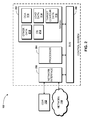
- the illustrated control system 102 includes a data storage device 202 ("memory”), a data processing unit 204 ("processor”), and a network interface 206, each of which is operatively connected to a system bus 208 that enables bi-directional communication between the memory 202, the processor 204, and the network interface 206.
- a data storage device 202 (“memory”)
- processor data processing unit
- network interface 206 each of which is operatively connected to a system bus 208 that enables bi-directional communication between the memory 202, the processor 204, and the network interface 206.
- the memory 202, the processor 204, and the network interface 206 are illustrated as unitary devices, some embodiments of the control system 102 include multiple processors, multiple memory devices, and/or multiple network interfaces.
- the processor 204 may include a standard central processor that performs arithmetic and logical operations, a more specific purpose programmable logic controller ("PLC"), a programmable gate array, or other type of processor known to those skilled in the art and suitable for controlling the operation of the control system 102.
- PLC programmable logic controller
- Data processing devices such as the processor 204 are well-known in the art, and therefore are not described in further detail herein.
- the memory 202 is illustrated as communicating with the processor 204 via the system bus 208, in some embodiments, the memory 202 is operatively connected to a memory controller (not shown) that enables communication with the processor 204 via the system bus 208. Furthermore, although the memory 202 is illustrated as residing at the control system 102, it should be understood that the memory 202 may include a remote data storage device accessed by the control system 102, for example the CDR 112. Therefore, it should be understood that the illustrated memory 202 can include one or more databases or other data storage devices communicatively linked with the control system 102.
- the network interface 206 enables the control system 102 to communicate with other networks or remote systems, for example, the FCMS's 104, the CMM's 108, one or more elements of the network 118, the CDR 112, databases, other devices, combinations thereof, and the like.
- Examples of the network interface 206 include, but are not limited to, a modem, a radio frequency ("RF") or infrared ("IR”) transceiver, a telephonic interface, a bridge, a router, and a network card.
- RF radio frequency
- IR infrared
- the network 118 includes, in some embodiments, a WLAN, a WWAN, a WPAN, a WMAN, a WAN, a LAN, a PAN, a MAN, and/or combinations thereof.
- the control system 102 also may access a public switched telephone network ("PSTN").
- PSTN public switched telephone network
- the memory 202 is configured for storing computer executable instructions that are executable by the processor 204 to make the control system 102 operative to provide the functions described herein. While embodiments will be described in the general context of program modules that execute in conjunction with application programs that run on an operating system on the control system 102, those skilled in the art will recognize that the embodiments also may be implemented in combination with other program modules. For purposes of clarifying the disclosure, the instructions are described as a number of program modules. It must be understood that the division of computer executable instructions into the illustrated and described program modules may be conceptual only, and is done solely for the sake of conveniently illustrating and describing the control system 102 and the functions performed thereby. In some embodiments, the memory 202 stores all of the computer executable instructions as a single program module.
- the memory 202 stores part of the computer executable instructions, and another system and/or data storage device stores other computer executable instructions.
- the control system 102 may be embodied in a unitary device, or may function as a distributed computing system wherein more than one hardware and/or software modules provide the various functions described herein.
- program modules include applications, routines, programs, components, software, software modules, data structures, and/or other types of structures that perform particular tasks or implement particular abstract data types.
- embodiments may be practiced with other computer system configurations, including hand-held devices, multiprocessor systems, microprocessor-based or programmable consumer electronics, minicomputers, mainframe computers, and the like.
- the embodiments may also be practiced in distributed computing environments where tasks are performed by remote processing devices that are linked through a communications network.
- program modules may be located in both local and remote memory storage devices.
- the program modules described herein may be stored at a data storage device such as the memory 202.
- the memory 202 may include any type of computer-readable media including volatile and non-volatile, removable and non-removable media implemented in any method or technology for storage of information such as computer-readable instructions, data structures, program modules, or other data.
- Computer-readable media further includes, but is not limited to, RAM, ROM, Erasable Programmable ROM (“EPROM”), Electrically Erasable Programmable ROM (“EEPROM”), flash memory or other solid state memory technology, CD-ROM, digital versatile disks (“DVD”), or other optical storage, magnetic cassettes, magnetic tape, magnetic disk storage or other magnetic storage devices, or any other medium that can be used to store the desired information and which can be accessed by the contour control system 100 and/or the contour control application 110.
- the memory 202 stores the contour control application 110.
- the contour control application 110 is executable by the processor 204 to retrieve and/or receive data associated with the CMM's 108, for example structure surface contour measurements ("actual contour data") or other data. Additionally, the contour control application 110 is executable by the processor 204 to retrieve and/or receive data associated with the FCM's 104, for example, loads sensed at the FCM's 104 and/or forces applied by the FCM's 104. As explained above, the contour control application 110 is executable by the processor 204 to retrieve, receive, and/or analyze the data associated with the FCM's 104 and/or the CMM's 108, the load data 114, the target contour data 116, other data, combinations thereof, and the like. The load data 114 may be stored at the CDR 112, the memory 202, and/or another data storage device and associated with a particular structure 106.
- the load data 114 includes data indicating forces measured at the FCM's 104 of the contour control system 100.
- a first manufacturing facility determines the load data 114 associated with the structure, stores the load data 114 at a data storage location such as the CDR 112, associates the load data 114 with the structure 106, and then transports the structure 106 to a second manufacturing facility.
- the second manufacturing facility retrieves the load data 114 from the data storage location and uses the load data 114 to control the contours of the structure 106.
- a contour control system 100 of the second manufacturing facility may apply the load data 114 to the structure 106, i.e., the contour control system can configure the FCM's 104 of the system to reproduce the stored load data 114, thereby avoiding determining how to configure the FCM's 104 to provide the desired contours of the structure 106.
- the memory 202 includes one or more storage locations for the load data 114 and/or the target contour data 116.
- the load data 114 and/or the target contour data 116 may be stored at an alternative data storage device such as, for example, the CDR 112.
- the memory 202 may store some, all, or none of the load data 114 and/or the target contour data 116.
- the memory 202 also stores other data 210.
- the other data 210 includes data and instructions.
- the other data 210 can include operating statistics, authentication data, user information, manufacturing statistics, quality control data and applications, data caches, data buffers, user interface applications, additional programs, applications, program modules, data, combinations thereof and the like.
- the memory 202 includes an operating system 212.
- operating systems include, but are not limited to, WINDOWS, WINDOWS CE, and WINDOWS MOBILE from MICROSOFT CORPORATION, LINUX, SYMBIAN from SYMBIAN LIMITED, BREW from QUALCOMM CORPORATION, MAC OS from APPLE CORPORATION, and FREEBSD operating system.
- the control system 102 also may include a random access memory (“RAM”) and a read-only memory (“ROM”).
- the ROM can store, for example, a basic input/output system ("BIOS”) containing the basic routines that help to transfer information between elements within the control system 102, such as during startup.
- BIOS basic input/output system
- control system 102 further includes a mass storage device for storing additional and/or alternative application programs and program modules.
- the mass storage device can be connected to the processor 204 through a mass storage controller (not shown) connected to the bus 208.
- the mass storage device and its associated computer-readable media provide non-volatile storage for the control system 102.
- computer-readable media can be any available media that can be accessed by the control system 102, including the various types of computer-readable media set forth above.
- the control system 102 also may include an input/output controller (not illustrated) for receiving and processing input from one or more input devices such as, for example, a keyboard, mouse, electronic stylus, and the like (not shown). Similarly, an input/output controller may provide output to a display screen, a printer, or other type of output device (not shown).
- the FCM 104 is configured to provide a moveable support to control the contours of the structure 106. Additionally, the FCM 104 is configured to apply forces to the structure 106 to maintain or adjust the contours of the structure 106.
- a number of FCM's 104 are positioned at supporting locations around the structure 106. The precise number and positions of the supporting locations may be determined using any known engineering techniques such as finite element analysis.
- the structure 106 is a rigid structure that has a relatively uniform mass distribution and relatively little weight
- relatively fewer FCM's 104 may be used than would be used if the structure 106 is a heavy flexible structure with uneven mass distribution.
- the FCM's 104 may be evenly spaced around or under the structure 106, while in the latter scenario, the FCM's 104 may be grouped more closely under the heavier portions of the structure 106 to limit the deflection of the structure 106 between the FCM's 104.
- FCM's 104 may be employed to apply forces to the top or sides of the structure to assist in form-fitting the structure 106 to a cradle or other manufacturing assembly device that also relies upon gravity to maintain the structure 106 in a desired position for manufacturing and/or assembly.
- FCM's 104 include "smart jacks" and/or other devices disclosed in co-pending U.S. Pat. App. Ser. No. 11/944,872 , entitled “Controlled Application of External Forces to a Structure for Precision Leveling and Securing,” which is hereby incorporated by reference in its entirety.
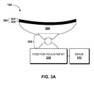
- the illustrated FCM 104 includes a load surface 300.
- the load surface 300 is configured to contact a surface of the structure 106 to bear a force and/or selectively apply a force to the structure 106.
- the load surface 300 includes a structure contact surface layer 302 disposed above a load sub-surface layer 304, though this is not necessarily the case.
- the load surface 300 includes, in some embodiments, additional and/or alternative layers.
- one or more layers 302, 304 of the load surface 300 include an air cushion contact pad configured to be selectively activated to apply a force to a surface of the structure 106.
- one or more layers 302, 304 of the load surface 300 includes a rubber contact pad configured to contact a surface of the structure 106.
- the load surface 300 is configured to support the structure and/or to apply a static or dynamic force to a surface of the structure 106.
- Other configurations of the load surface 300 are possible, and are contemplated.
- one or more layers 302, 304 of the load surface 300 may include a vacuum cup for applying a force to a surface of the structure 106.
- the vacuum cup embodiment of the FCM 104 is configured to pull a surface of the structure to support the structure 106 and/or to deform the structure 106 to control one or more structure contours, as discussed above.
- the FCM 104 includes a support structure 306, which can include a composite, aluminum, or other material that functions as a support sub-structure for the load surface 300.
- the support structure 306, if included, can perform several functions.
- the support structure 306 can provide rigidity for the load surface 300, particularly if the load surface 300 is soft and/or pliable, as is often the case with a rubber pad, an air cushion layer, and/or a vacuum cup layer.
- the support structure 306 can be configured to bear forces transferred between the FCM 104 and the surface of the structure 106 to reduce strain on the load surface 300 and/or the layers 302, 304 thereof.
- the FCM 104 includes a centering mechanism 308.
- the centering mechanism 308 may include, but is not limited to, a split gimbal self-centering support bearing, a ball and socket joint, or other centering mechanisms.
- the FCM 104 also can include a position adjusting mechanism 310 for adjusting the position of the load surface 300 with respect to the surface of the structure 106.
- the position adjusting mechanism 310 includes, in some embodiments, a height adjustment mechanism for adjusting the height of the FCM 104 and/or components thereof.
- the height adjustment mechanism can include a servomotor, a hydraulic actuator, a pneumatic actuator, pneumatically driven pistons or other devices, threaded sleeves and reciprocally threaded shafts, adjustable parallel tooling, adjustable jacks, other height adjustment mechanisms, and the like.
- the position adjusting mechanism 310 also includes, in some embodiments, mechanisms for adjusting the position of the load surface 300 in the ⁇ x-axis' and the 'y-axis.
- the FCM 104 therefore may include various devices for adjusting the position of the load surface 300 with respect to a surface of the structure 106.
- the position adjusting mechanism 310 may be driven by a drive 312, which may include motors, air lines, vacuum lines, switches, pressure controllers, jacks, gears, electronic controls, combinations thereof, and the like.
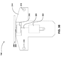
- FIGURE 3B illustrates an FCM 104, according to another exemplary embodiment of the present disclosure.
- the FCM 104 includes a lower support plate 314.
- the lower support plate 314 mates with an upper support plate (not illustrated in FIGURE 3B ), though this is not necessarily the case.
- the lower support plate 314 includes connection mechanisms 316 for connecting the FCM 104 to a desired structure, for example, a support cradle, as will be shown and discussed below with reference to FIGURES 4B-4D .
- the connection mechanisms 316 are illustrated as apertures for receiving a rod, screw, bolt, rivet, and/or another connector, though this embodiment is exemplary and should not be construed as being limiting in any way.
- the lower support plate 314 includes a linear bearing 318 through which a connection rod 320 passes.
- the linear bearing can be any known linear bearing including, but not limited to, a closed linear pillow block bearing.
- the connection rod 320 is connected to the load surface 300 or a component thereof via the centering mechanism 308 on one end, and to a force sensor 322, for example, a force sensing actuator, on the other end.
- the force sensor 322 may be a load cell, a pressure gauge, a piezoelectric sensor, or any other type of force sensor capable of measuring the quantity of force applied to the structure 106 by the FCM 104 and/or to the FCM 104 by the structure 106.
- Suitable examples of the force sensor 322 include, but are not limited to, force measuring actuators sold by Exlar Corporation of Chanhassen, MN under the mark EXLAR®, including model numbers GSX30, GSX40, GSX50, GSX60, IS30 and IS40.
- the force sensor 322 may be located as shown, or may be located in any other suitable position for sensing and/or measuring the force between the FCM 104 and the structure 106.
- the force sensor 322 can be used to provide the FCM 104 with the ability to measure a force measured between the FCM 104 and a structure in contact with the FCM 104, for example, the structure 106.
- the forces sensed by the FCM 104 can be reported to the contour control system 100 to be used to determine the contours of the structure 106.
- the contour control system 100 is configured to use the CMM's 108 and/or the FCM's 104 to determine the contours of the structure 106.
- the FCM 104 can be activated via the control system 102 or another device.
- a force sensing actuator 322 is merely exemplary and should not be construed as being limiting in any way. Additional and alternative embodiments are described herein.
- the FCM 104 may be coupled to a position adjusting mechanism 310 and/or a drive 312, as discussed with reference to FIGURE 3A .
- the position adjusting mechanism 310 and/or the drive 312 are operative to adjust the position of the FCM 104 with respect to the structure 106, and may be controlled by the control system 102 and/or the contour control application 110 as explained herein.
- the contour control application 110 may be conducted over one or more wired and/or wireless networks or network components, or may be via a direct wired and/or wireless link. Regardless of the type of connection used, the contour control application 110 is operative to send control commands to the FCM 104 or a component thereof, for example, the position adjusting mechanism 310 and/or the drive 312, to control the position of and/or a force applied by the FCM 104 to the structure 106. Furthermore, the contour control application 110 is operative to receive data indicating the force applied to or by the FCM 104, and to use that data to determine whether the position of and/or the force applied by the FCM 104 should be adjusted to control a contour of the structure 106. Thus, the contour control application 110 is able to control the amount of force applied to the structure 106 by the FCM 104 and/or the location of the force applied to the structure 106 by the FCM 104 to control one or more contours of the structure 106.
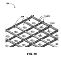
- FIGURE 3C illustrates a portion of a surface of an FCM 104, according to another exemplary embodiment of the present disclosure.
- the FCM 104 illustrated in FIGURE 3C employs an array of air pressure application cells 324.
- Each of the air pressure application cells 324 can include contact surfaces 326 that contact the surface of the structure 106.
- the contact surfaces 326 can include pliable or malleable ridges so that the contact surfaces 326, and therefore the FCM 104, mold to the surface of the structure 106.
- each air pressure application cell 324 can be sealed against the structure so that air pressure can be controlled at the surface 106 corresponding to each of the air pressure application cells 324.
- the contact surfaces 326 include compressible blue rubber baffles that include .200 inches in compressible height. It should be understood that this embodiment is exemplary, and that other materials and compressible heights are both possible and contemplated.
- each of the air pressure application cells 324 further can include a pressurized air intake port 328 and a pressure sensor (not visible).
- the pressure sensors measure pressure at each air pressure application cell 324.
- the measured pressure can be transmitted or fed back to the control system 102, which can analyze the measured pressure as force or load data 114.
- the control system 102 can be configured to control the flow of air to each of the air pressure applications cells 324 to regulate, change, activate, and/or deactivate air pressure at each individual air pressure application cell 324.
- the air pressure application cells 324 also can include a position adjustment device and a drive, which can function in a manner similar to the position adjustment device 310 and the drive 312 illustrated and described with reference to FIGURE 3A .
- each air pressure application cell 324 includes a ball screw drive, mounted under each air pressure application cell 324, for adjusting the position of the air pressure application cell 324.
- An FCM 104 constructed in accordance with FIGURE 3C can be used to evenly distribute support forces over a large surface of the structure 106, and to help avoid destructive single point loads that may be applied to the structure 106 if using other support structures.
- FIGURE 4A illustrates a structure support cradle 400 ("cradle"), according to an exemplary embodiment of the present disclosure.
- the cradle 400 includes a contact surface 402 that contacts a surface of the structure 106.
- the cradle 400 includes one or more cradle modules 404 that collectively join together to provide the support surface 402 and the other structures described herein.
- the cradle 400 includes a substantially unitary structure.
- the cradle 400 need not include the cradle modules 404, and that the illustrated embodiment is merely exemplary and should not be construed as being limiting in any way.
- the cradle modules 404 include ribs 406 and apertures 408. Ribs 406 may be included to provide or increase rigidity and support for the support surface 402, but are not always necessary and therefore may be omitted in some embodiments.
- the cradle 400 can include one or more FCM's 104. In some embodiments, the FCM's 104 are disposed such that the load surfaces 300 of respective FCM's 104 are flush with the contact surface 402, below the contact surface 402, or above the contact surface 402.
- the illustrated configuration i.e., the load surfaces 300 of respective FCM's 104 being disposed above the contact surface 402 is provided for purposes of clarifying the concepts of the present disclosure and should not be construed as being limiting in any way.
- the contact surface 402 supports a surface of the structure 106 and the FCM's 104 are used to measure forces at the locations of the FCM's 104 and/or to apply additional support or forces to the surface of the structure 106 to control contours of the structure 106.
- FIGURE 4B illustrates placement of an FCM 104 according to an exemplary embodiment of the present disclosure.
- the FCM 104 includes the lower support plate 314 as described above with reference to FIGURE 3 B.
- the FCM 104 also includes the upper support plate 410 mentioned above, which is configured to be connected to the lower support plate 314 using connectors 412, 414.
- the illustrated connectors 412, 414, as well as the numbers of connectors and the placement thereof, are merely exemplary and should not be construed as being limiting in any way.
- the FCM 104 is configured to be connected to a cradle module 404 via the connectors 412, 414 and an FCM attachment plate 416.
- the FCM attachment plate 416 includes a throughhole 418 through which the connector 412 passes, though this method of attaching the FCM attachment plate 416 to the FCM 104 is merely exemplary. As illustrated, the FCM 104 can be connected between two cradle modules 404 using the connectors 412, 414 and the FCM attachment plates 416.
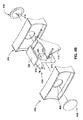
- FIGURE 4C illustrates a perspective view of the FCM 104 and cradle modules 404 of FIGURE 4B .
- FIGURE 4D illustrates a top view of three FCM's 104 attached between two cradles 400.
- the support surfaces 402 of the cradles 400 are visible, as are the load surfaces 300 of the FCM's 104.
- the load surfaces 300 may have alternative shapes and configurations, and that the illustrated embodiment is merely exemplary.
- FIGURE 4D only the load surfaces 300 of the FCM's 104 are visible, though this is not necessarily the case.
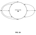
- FIGURE 5A placement of the CMM's 108 with respect to the structure 106 is illustrated, according to an exemplary embodiment of the present disclosure.
- the structure 106 can be supported by support structures such as, for example, the cradle 400.
- a radial array of CMM's 108 are disposed at the surface of the structure 106.
- eight CMM's 108 are included, though other numbers of CMM's 108 are possible and are contemplated.
- the CMM's 108 are illustrated as being adjacent the surface of the structure 106, it should be understood, as explained above, that in some embodiments, the CMM's 108 include one or more laser radar or laser tracker devices placed proximate to an inner or outer surface of the structure 106.
- the effective range of some laser radar and/or laser tracker devices can be between one and sixty meters, or even greater. Therefore, the CMM's 108 may be placed a substantial distance away from the structure 106.
- the number of the CMM's 108, as well as the respective locations and placement of the CMM's 108, can be determined based upon the needs associated with the structure 106 and/or the limitations and/or needs of a particular application of the contour control system 100 and/or the type of device used to provide the functions of the CMM 108. For example, for low tolerance applications, i.e., for applications where high accuracy and precision are required, more CMM's 108 may be used than are used for relatively high tolerance applications wherein a relatively lower level of accuracy and precision are required. Again, the exact number of CMM's 108 and the placement thereof will vary depending upon the application. With an understanding of the concepts of the present disclosure, one of ordinary skill in the art will be able to determine the number of CMM's 108 to be employed and the respective placement thereof, without undue experimentation.
- the CMM's 108 can determine the locations and/or configurations of one or more surfaces of the structure 106, one or more surface contours of the structure 106, and/or one or more points of the structure 106.
- the CMM's 108 can output these determined locations and/or configurations as data that is interpretable by the contour control system 100 as indicating the locations and/or configurations of the contours of the structure 106.
- the contour control system 100 may compare the determined locations and/or configurations of the contours of the structure 106 to the desired structure contours and can determine forces that should be applied to the structure 106 to manipulate the structure 106 to generate the desired structure contours.
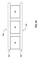
- FIGURE 5B placement of the FCM's 104 and the cradle 400 with respect to the structure 106 is illustrated, according to an exemplary embodiment of the present disclosure.
- the structure 106 is supported by the cradle 400.
- the cradle 400 includes a number of FCM's 104, for example the FCM's 104 illustrated in FIGURES 3A-4D .
- a number of FCM's 104 are disposed at several locations around the surface of the structure 106.
- the FCM's 104 include vacuum cups and the cradle 400 includes seven FCM's 104 that include air cushion contact pads. Additional and/or alternative FCM's 104 are possible and are contemplated.
- the contour control application 110 is operative to compare the actual contour data associated with the structure 106, for example data obtained by the FCM's 104 and/or the CMM's 108, to design data such as the target contour data 116 to determine if the contours of the structure 106 are consistent with the intended design and any allowed tolerances.
- the contour control application 110 also is operative to receive force/load data measured by the FCM's 104.
- the force/load data can be stored in the memory 202, the CDR 112, or at another data storage device as, for example, the load data 114.
- This load data 114 may be stored when the contours of the structure 106 are in a desired configuration, such that that another contour control system 100 can replicate the desired contour configurations without having to reanalyze and measure the surface contours. As explained, this embodiment may be particularly useful when the structure 106 is manufactured, stored, and/or assembled at more than one facility.
- the contour control application 110 also is operative to analyze the actual contour data obtained by the CMM's 108 and/or the force/load data measured at the FCM's 104 to determine if the structure 106 is consistent with a desired design and any associated tolerances.
- the analysis of the target contour data 116, the load data 114, and/or the actual contour data data provided by the CMM's 108 and/or the FCM's 104 can be used by the contour control application 110 to determine if any forces should be applied to the surfaces of the structure 106 to manipulate the structure 106 to correct deviations between the target contour data 116 and the actual contour data associated with the structure 106.
- the contour control application 110 relies only upon the load data 114 associated with the FCM's 104 to determine if any forces should be applied to or removed from the structure 106.
- each FCM 104 can have a calculated target force value and associated tolerances, wherein the target force values may be calculated for FCM 104 at each FCM 104 location.
- the target force values are forces that, if applied at the locations associated with respective FCM's 104, should result in the desired structure contours of the structure 106.
- the contour control application 110 monitors the forces applied and/or sensed at each FCM 104 to determine if the forces deviate from the corresponding threshold range of force values. Once the contour control application 110 determines that a particular force measurement is out of tolerance, or out of a pre-determined threshold range of force values, then the contour control application 110 is operative to activate the associated FCM 104 to apply or remove force between the FCM 104 and the structure 106 until the force measurement is again within tolerance, or within the pre-determined threshold range of force values.
- the target force values and corresponding threshold ranges of acceptable force values can be established using known engineering analysis tools and techniques such as finite element analysis when the locations for each FCM 104 and the quantity of the FCM's 104 are determined. It should be appreciated that the quantity of FCM's 104, the locations of each of the FCM's 104, the target forces applied by each of the FCM's 104, and the threshold range of acceptable force values for each FCM 104 may be calculated by the contour control application 110 after receiving input regarding the characteristics of the structure 106, for example the target contour data 116 and/or the actual contour data obtained by the CMM's 108 and/or the FCM's 104, or may be input into the contour control application 110 by an authorized entity.
- FIGURE 6 a method 600 for controlling structure contours using the contour control system 100 will now be described in detail. It should be understood that the operations of the method 600 are not necessarily presented in any particular order and that performance of some or all of the operations in an alternative order(s) is possible and is contemplated. The operations have been presented in the demonstrated order for ease of description and illustration. Operations may be added, omitted, and/or performed simultaneously, without departing from the scope of the appended claims. It also should be understood that the illustrated method 600 can be ended at any time and need not be performed in its entirety.
- Some or all operations of the method 600, and/or substantially equivalent operations, can be performed by execution of computer-readable instructions included on a computer-storage media, as defined above.
- computer-readable instructions and variants thereof, as used in the description and claims, is used expansively herein to include routines, applications, application modules, program modules, programs, components, data structures, algorithms, and the like.
- Computer-readable instructions can be implemented on various system configurations, including single-processor or multiprocessor systems, minicomputers, mainframe computers, personal computers, hand-held computing devices, microprocessor-based, programmable consumer electronics, combinations thereof, and the like.
- the logical operations described herein are implemented (1) as a sequence of computer implemented acts or program modules running on a computing system and/or (2) as interconnected machine logic circuits or circuit modules within the computing system.
- the implementation is a matter of choice dependent on the performance and other requirements of the computing system.
- the logical operations described herein are referred to variously as states operations, structural devices, acts, or modules. These operations, structural devices, acts, and modules may be implemented in software, in firmware, in special purpose digital logic, and any combination thereof.
- the method 600 is described as being performed by the contour control system 100, though this embodiment is merely exemplary.
- the method 600 begins at operation 602, wherein the contour control system 100 determines if deformation data associated with the structure 106 has been received.
- the deformation data indicates how the structure 106 deviates from a desired structure design and can be used by the contour control system 100 to determine how to manipulate the structure 106 to obtain the desired contours.
- the deformation data can include the load data 114, which can indicate the loads needed at the FCM's 104 to manipulate the structure 106 to obtain the desired contours.
- the load data 114 can be received from a manufacturing, assembly, or storage facility, or from an entity transporting the structure 106.
- the load data 114 is generated and/or retrieved from the FCM's 104 of the contour control system 100.
- some embodiments of the method 600 are performed by one contour control system 100 and some embodiments of the method 600 are performed by two or more contour control systems 100.
- the method 600 proceeds to operation 604, wherein the contour control system 100 determines the actual contour data associated with the structure 106 ("actual contour data"), i.e., data indicating the location and configuration of the contours of the structure 106, so the contour control system 100 can determine if the structure contours deviate from contours associated with a desired structure design.
- the contour control system 100 is operative to measure the structure 106, e.g. , to receive and/or retrieve data from the CMM's 108 and/or the FCM's 104 to determine the actual contours of the structure 106.
- the contour control system 100 can obtain the actual contour data from a number of contact and/or contactless measuring devices including, for example, the FCM's 104 and/or the CMM's 108.
- the method proceeds to operation 606, wherein the contour control system 100 obtains target contour data 116 associated with the structure 106.
- the contour control system 100 is configured to retrieve target contour data 116 indicating the specified contour locations, configurations, and/or associated tolerances.
- the target contour data 116 is stored at a data storage device such as, for example, hard drive, a memory, a database, a server, or the like, for example the CDR 112.
- the operation 606 includes, in some instances, communicating with the CDR 112 to determine if target contour data 116 associated with the structure 106 is available, and retrieving the target contour data 116, if available.
- the method 600 proceeds to operation 608 after operation 606, or after operation 602 if the contour control system 100 determines at operation 602 that the deformation data is available.
- the contour control system 100 is configured to retrieve target contour data 116 indicating the specified contour locations, configurations, and/or associated tolerances.
- the target contour data 116 is analyzed by the contour control system 100 to determine forces to apply to the structure 106.
- the contour control system 100, or a contour control application 110 of the contour control system 100 is operative to compare the retrieved or received shape data to the target contour data 116 indicating desired design contours for the structure 106 and can determine how to manipulate the structure 106 to obtain the desired contours.
- the contour control system 100 is configured to analyze actual contour data that is measured by the FCM's 104, without relying upon measurements collected by the CMM's 108, to determine if the actual contours of the structure 106 deviate from the contours of the targeted design of the structure 106.
- the contour control system 100 is operative to analyze actual contour data retrieved from various sensors and measurement devices, including the FCM's 104 and/or the CMM's 108 , to determine if the contours of the structure are consistent with a desired design and any associated tolerances. Regardless of which measurement devices the contour control system 100 uses to obtain the actual contour data, the contour control system 100 is configured to retrieve the target contour data 116 from the memory 202 and/or the CDR 112 and comparing the target contour data 116 to the actual contour data.
- operation 608 includes, in some embodiments, retrieving load data 114 from the memory 202 and/or the CDR 112, and comparing the load data 114 to the actual contour data in the form of measured force/load data retrieved from the FCM's 104.
- the contour control system 100 determines not only if the structure contours are within tolerance of the desired structure contours, but also the extent to which the structure contours deviate from the desired structure contours. Thus, the contour control system 100 determines how to manipulate the structure 106 to control the contours of the structure 106 such that the contours of the structure 106 will be within tolerance of the targeted design contours.
- the method 600 proceeds to operation 610, whereat the contour control system 100 applies the determined forces to the structure 106.
- the contour control system 100 uses the forces determined in operation 608 to control the FCM's 104 .
- the contour control system 100 may inflate one or more air cushion pads of the FCM's 104, deflate one or more air cushion pads of the FCM's 104, increase suction of one or more vacuum cups of the FCM's 104, decrease suction of one or more vacuum cups of the FCM's 104, bring one or more FCM's 104 into or out of contact with the structure, or adjust the position of one or more FCM's 104.
- the contour control system 100 applies any forces determined by the contour control system 100 to be needed to adjust the contours of the structure 106. It should be understood that the forces needed to adjust the contours of the structure 106 may be obtained from deformation data passed to the contour control system 100 from another entity and/or determined by the contour control system 100, for example, as determined in operation 608 or in accordance with other operations.
- the method 600 proceeds to operation 612, wherein one or more assembly, manufacturing, or other operations are performed on the structure 106.
- two structures 106 may be mated together while the respective contours of the structures 106 are adjusted to the desired configurations. Because the respective contours of the structures 106 may be controlled, the assembly, manufacturing, and/or other operations may be simplified and additional labor may be avoided.
- the mating of two or more fuselage sections of an aircraft requires that the two fuselage sections be similarly configured. During transit of the fuselage sections, the surface contours of the sections may move, complicating the mating steps.
- assembly facilities may include shim production facilities such that gaps between the mated components may be minimized and/or eliminated.
- manufacturing facilities employing a contour control system 100 such as that disclosed herein may be able to manipulate the respective components such that less manpower and/or materials are needed to complete the assembly operations.
- These and other operations associated with assembling, machining, manufacturing, and/or transporting the structure 106 may be simplified, and/or the costs and time required to perform these operations may be reduced, using the methods and systems disclosed herein.
- the method proceeds to operation 614, wherein the contour control system 100 verifies the structure contours, i.e., the contour control system 100 can determine if the shape of the structure 106 is consistent with the desired contours and associated tolerances of a desired structure 106.
- the contour control system 100 is configured to store load data 114 at any time. For example, the contour control system 100 can store the load data 114 when the contours of the structure 106 are determined to be consistent with the desired structure contours and the associated tolerances.
- the loads associated with all FCM's 104 can be stored as load data 114.
- the load data 114 can be stored at the memory 202, the CDR 112, and/or another data storage device. If the structure 106 is transported to another entity, the load data 114 may be transported with the structure 106 and/or stored in a data storage device accessible by the other entity. The method 600 ends.
- the contour control system 100 is configured to continuously monitor and control the contours of the structure 106.
- the devices and methods described above may be continuously employed to maintain the structure 106 in the targeted configuration during a particular operation, e.g. , an assembly, machining, manufacturing, and/or transportation operation.
- a particular operation e.g. , an assembly, machining, manufacturing, and/or transportation operation.
- additional structures and components may be added to the structure 106.
- flooring, stringers, attachment mechanisms, doors, windows, wiring, wiring harnesses, electronics, plumbing, seating, trim, other structures, combinations thereof, and the like, may be added. These components contribute weight to the structure 106 and adding these structures to the structure 106 may alter the shape or configuration of the structure 106.
- the ability to continuously monitor and adjust the FCM's 104 to maintain the structure 106 in the desired configuration may greatly reduce the variations sometimes experienced in aircraft fuselage manufacturing, assembly, and/or other operations.
- the load data 114 associated with the FCM's 104 can be stored at any time and can be passed to another entity.
- the structure 106 may be transported to another entity that can access the load data 114. Therefore, the other entity will have the ability to return the structure to the desired shape with little effort, instead simply importing the load data 114 to the contour control system 100 and applying that load data 114 to the structure 106.
Landscapes
- Engineering & Computer Science (AREA)
- Manufacturing & Machinery (AREA)
- Transportation (AREA)
- Aviation & Aerospace Engineering (AREA)
- Automatic Assembly (AREA)
- Manipulator (AREA)
- Moulds For Moulding Plastics Or The Like (AREA)
- Force Measurement Appropriate To Specific Purposes (AREA)
Applications Claiming Priority (1)
| Application Number | Priority Date | Filing Date | Title |
|---|---|---|---|
| US12/697,752 US8774971B2 (en) | 2010-02-01 | 2010-02-01 | Systems and methods for structure contour control |
Publications (3)
| Publication Number | Publication Date |
|---|---|
| EP2354005A2 true EP2354005A2 (de) | 2011-08-10 |
| EP2354005A3 EP2354005A3 (de) | 2013-11-27 |
| EP2354005B1 EP2354005B1 (de) | 2020-07-22 |
Family
ID=43920018
Family Applications (1)
| Application Number | Title | Priority Date | Filing Date |
|---|---|---|---|
| EP11152746.1A Active EP2354005B1 (de) | 2010-02-01 | 2011-01-31 | Systeme und Verfahren zur Steuerung der Strukturkonturen |
Country Status (3)
| Country | Link |
|---|---|
| US (1) | US8774971B2 (de) |
| EP (1) | EP2354005B1 (de) |
| CA (1) | CA2727694C (de) |
Families Citing this family (15)
| Publication number | Priority date | Publication date | Assignee | Title |
|---|---|---|---|---|
| US8700191B2 (en) | 2007-11-26 | 2014-04-15 | The Boeing Company | Controlled application of external forces to a structure for precision leveling and securing |
| DE102011010315A1 (de) * | 2011-02-03 | 2012-08-09 | Hönigsberg & Düvel Datentechnik GmbH | Erkennung von Objekten |
| US8747188B2 (en) | 2011-02-24 | 2014-06-10 | Apple Inc. | Smart automation of robotic surface finishing |
| DE102012209320A1 (de) * | 2012-06-01 | 2013-12-05 | Airbus Operations Gmbh | Verfahren und Lagervorrichtung zum Lagern und Ausrichten eines Bauteils |
| US9971339B2 (en) | 2012-09-26 | 2018-05-15 | Apple Inc. | Contact patch simulation |
| WO2015198174A1 (en) * | 2014-06-27 | 2015-12-30 | Bombardier Inc. | Reshaping of deformed components for assembly |
| US9927227B2 (en) | 2014-09-17 | 2018-03-27 | The Boeing Company | Metrology system for generating measurements of fuselage sections |
| US9682788B2 (en) | 2014-09-17 | 2017-06-20 | The Boeing Company | Fuselage manufacturing system |
| US11131982B2 (en) * | 2014-09-17 | 2021-09-28 | The Boeing Company | Fuselage manufacturing system |
| US11273930B2 (en) * | 2014-09-17 | 2022-03-15 | The Boeing Company | Cradle system for shaping fuselage sections |
| US10035230B2 (en) * | 2015-07-02 | 2018-07-31 | The Boeing Company | Active fixturing device and system |
| IT201900020156A1 (it) * | 2019-10-31 | 2021-05-01 | Fondazione St Italiano Tecnologia | Metodo per il controllo della forza di un dispositivo di azionamento pneumatico |
| TWI707740B (zh) * | 2019-11-26 | 2020-10-21 | 財團法人工業技術研究院 | 可調式工件支撐系統及方法 |
| TWI764405B (zh) * | 2020-12-03 | 2022-05-11 | 財團法人工業技術研究院 | 調整支撐工件方法及可調式支撐工件系統 |
| US12371190B2 (en) * | 2023-05-03 | 2025-07-29 | The Boeing Company | Manufacturing systems and methods for shaping and assembling flexible structures |
Family Cites Families (63)
| Publication number | Priority date | Publication date | Assignee | Title |
|---|---|---|---|---|
| US4081992A (en) | 1976-11-22 | 1978-04-04 | Farmer Foundation Company, Inc. | Apparatus for load testing foundation shafts |
| FR2570020B1 (fr) | 1984-09-11 | 1988-07-22 | Commissariat Energie Atomique | Presse automatique |
| CH667532A5 (fr) | 1986-02-13 | 1988-10-14 | Bobst Sa | Dispositif pour mesurer la force de decoupage et limiter les surcharges dans une presse a platines. |
| US4736633A (en) | 1986-03-25 | 1988-04-12 | Fmc Corporation | Multipurpose lifting and pulling vehicle |
| US4805652A (en) | 1987-09-21 | 1989-02-21 | Hoover Group, Inc. | Wash station for tanks |
| US5026245A (en) | 1989-06-29 | 1991-06-25 | Caterpillar Industrial Inc. | Clamping arrangement for a lift mast |
| US5547751A (en) | 1992-04-10 | 1996-08-20 | Mitsubishi Denki Kabushiki Kaisha | Magneto-optical recording medium and method of manufacturing the same |
| US5580095A (en) | 1993-06-28 | 1996-12-03 | Kabushiki Kaisha Komatsu Seisakusho | Vehicle body levelling device for a working vehicle having outriggers |
| US5374025A (en) | 1993-06-28 | 1994-12-20 | Alliedsignal Inc. | Fluidic vibration cancellation actuator and method |
| US6098000A (en) * | 1994-06-24 | 2000-08-01 | Mccord Winn Textron Inc. | Interactive, individually controlled, multiple bladder seating comfort adjustment system and method |
| US5596144A (en) | 1995-08-04 | 1997-01-21 | Delco Electronics Corporation | Piezoresistive force rebalance accelerometer |
| US5970665A (en) | 1996-10-02 | 1999-10-26 | Oudman; Jack A. | System and method for maintaining a building a structure in a level condition |
| TW434095B (en) * | 1997-08-11 | 2001-05-16 | Tokyo Seimitsu Co Ltd | Wafer polishing apparatus |
| US6560804B2 (en) * | 1997-11-24 | 2003-05-13 | Kci Licensing, Inc. | System and methods for mattress control in relation to patient distance |
| US6199427B1 (en) | 1997-12-04 | 2001-03-13 | Intercomp Company | Apparatus and method for testing leaf springs |
| FR2774573B1 (fr) * | 1998-02-09 | 2000-04-28 | Support Systems International | Procede et appareil de support d'un element a supporter, en particulier le corps d'un patient, a systeme integre d'equilibre dynamique et automatique de pression |
| US6422087B1 (en) * | 1998-07-15 | 2002-07-23 | Rostra Precision Controls, Inc. | Electronic control system for a variable support mechanism |
| WO2000003623A2 (en) * | 1998-07-15 | 2000-01-27 | Rostra Precision Controls, Inc. | Electronic control system for a variable support mechanism |
| US6088642A (en) * | 1998-07-29 | 2000-07-11 | Mccord Winn Textron Inc. | Interactive, individually controlled, multiple bladder seating comfort adjustment system and method |
| US6193442B1 (en) | 1999-03-16 | 2001-02-27 | Donald R. May | Method and device for raising and supporting a building foundation |
| US6776692B1 (en) * | 1999-07-09 | 2004-08-17 | Applied Materials Inc. | Closed-loop control of wafer polishing in a chemical mechanical polishing system |
| US6203105B1 (en) | 1999-08-20 | 2001-03-20 | Mccord Winn Textron Inc. | Vehicle impact responsive multiple bladder seating and headrest system and method |
| US7226057B2 (en) | 2000-03-10 | 2007-06-05 | Days Corporation | Apparatus and method for automatically leveling an object |
| US6619693B1 (en) | 2000-03-10 | 2003-09-16 | Days Corporation | Apparatus and method for automatically leveling an object |
| US6640685B2 (en) | 2001-02-07 | 2003-11-04 | David M. Hamby | Closed loop electrohydraulic actuator control circuit |
| US6439341B1 (en) | 2001-02-14 | 2002-08-27 | Snorkel International, Inc. | Apparatus for monitoring loading of a lift |
| US7669777B2 (en) | 2001-05-07 | 2010-03-02 | Automated Logic Corporation | Slope predictive control and digital PID control for a variable temperature control system |
| US6679504B2 (en) | 2001-10-23 | 2004-01-20 | Liquidspring Technologies, Inc. | Seamless control of spring stiffness in a liquid spring system |
| DE10314212B4 (de) * | 2002-03-29 | 2010-06-02 | Hoya Corp. | Verfahren zur Herstellung eines Maskenrohlings, Verfahren zur Herstellung einer Transfermaske |
| US6923599B2 (en) | 2002-06-24 | 2005-08-02 | Kenneth J. Kelso | In-ground lifting system and method |
| US6839883B2 (en) | 2002-08-08 | 2005-01-04 | Agilent Technologies, Inc. | Determining support locations in a wireless fixture of a printed circuit assembly tester |
| GB0308170D0 (en) | 2003-04-09 | 2003-05-14 | Rolls Royce Plc | A mounting arrangement and method |
| US7267345B2 (en) | 2003-04-23 | 2007-09-11 | Roberto Maggiori | Leveling instrument, an electromechanical lifter and a self leveling integrated lifting system using both of them |
| JP2005011977A (ja) * | 2003-06-18 | 2005-01-13 | Ebara Corp | 基板研磨装置および基板研磨方法 |
| US7152920B2 (en) * | 2003-10-21 | 2006-12-26 | Ts Tech Co., Ltd. | Vehicle seat with system for facilitating relieving of fatigue of person sitting on the seat |
| WO2005049457A2 (en) | 2003-11-18 | 2005-06-02 | Intelligrated, Inc. | Conveyor and support |
| EP1700088B1 (de) * | 2003-12-12 | 2012-06-06 | Hill-Rom Services, Inc. | Sitzkraftsensor |
| US20050159840A1 (en) * | 2004-01-16 | 2005-07-21 | Wen-Jong Lin | System for surface finishing a workpiece |
| US7369661B2 (en) | 2004-01-30 | 2008-05-06 | Intel Corporation | Method and apparatus for detection of loss of cipher synchronization |
| US7150673B2 (en) * | 2004-07-09 | 2006-12-19 | Ebara Corporation | Method for estimating polishing profile or polishing amount, polishing method and polishing apparatus |
| JP4098761B2 (ja) * | 2004-08-17 | 2008-06-11 | ファナック株式会社 | 仕上げ加工方法 |
| US7176391B2 (en) | 2004-09-13 | 2007-02-13 | Hill-Rom Services, Inc. | Load cell to frame interface for hospital bed |
| US7617018B2 (en) | 2004-10-18 | 2009-11-10 | Innovative Design Solutions | Platform attitude adjustment augmentation method and apparatus |
| US7208896B2 (en) | 2004-10-18 | 2007-04-24 | Innovative Design Solutions | Electric jack load balancing method and device |
| US7805784B2 (en) | 2005-12-19 | 2010-10-05 | Stryker Corporation | Hospital bed |
| TWI275451B (en) * | 2005-01-11 | 2007-03-11 | Asia Ic Mic Process Inc | Measurement of thickness profile and elastic modulus profile of polishing pad |
| SE528276C2 (sv) | 2005-02-14 | 2006-10-10 | Hans Nilsson | Klämkraftstyrning |
| US20060188329A1 (en) | 2005-02-22 | 2006-08-24 | Perimeter Defense Technologies, Lp | Method and apparatus for lifting a load |
| US7795547B2 (en) | 2005-06-03 | 2010-09-14 | Torben Winther Hansen | Method of weight determination of a load carried by a lifter of a lifting device and weighing device |
| DE102005036139B4 (de) | 2005-07-27 | 2008-11-13 | Jost-Werke Gmbh | Stützwinde mit Stützlastindikator |
| JP4281012B2 (ja) | 2005-09-30 | 2009-06-17 | 株式会社日立プラントテクノロジー | 揚重ジャッキの荷重バランス調整方法および装置、並びにジャッキアップ装置 |
| US7493194B2 (en) | 2005-10-04 | 2009-02-17 | Ravinder Venugopal | Method and system for achieving force control in externally driven hydraulic cylinders |
| US7559533B2 (en) | 2006-01-17 | 2009-07-14 | Gorbel, Inc. | Lift actuator |
| US20070175016A1 (en) | 2006-02-02 | 2007-08-02 | The Boeing Company | Method and apparatus for removing and replacing components of an airplane |
| US20070189887A1 (en) | 2006-02-15 | 2007-08-16 | Bellsouth Intellectual Property Corporation | Removing and installing portable storage containers |
| US7661910B2 (en) | 2006-05-18 | 2010-02-16 | Ross Guenther | Hydraulic elevation apparatus and method |
| JP4155527B2 (ja) | 2006-05-25 | 2008-09-24 | 新東工業株式会社 | 昇降装置の制御システム |
| US7503606B2 (en) | 2006-06-05 | 2009-03-17 | Hall David R | Lifting assembly |
| US7672817B2 (en) | 2006-11-08 | 2010-03-02 | The Boeing Company | Flight in factory |
| US7756321B2 (en) | 2007-02-28 | 2010-07-13 | The Boeing Company | Method for fitting part assemblies |
| US7787979B2 (en) | 2007-03-14 | 2010-08-31 | The Boeing Company | Splicing fuselage sections without shims |
| US8733707B2 (en) | 2008-04-17 | 2014-05-27 | The Boeing Company | Line transfer system for airplane |
| US8700191B2 (en) | 2007-11-26 | 2014-04-15 | The Boeing Company | Controlled application of external forces to a structure for precision leveling and securing |
-
2010
- 2010-02-01 US US12/697,752 patent/US8774971B2/en active Active
-
2011
- 2011-01-12 CA CA2727694A patent/CA2727694C/en active Active
- 2011-01-31 EP EP11152746.1A patent/EP2354005B1/de active Active
Also Published As
| Publication number | Publication date |
|---|---|
| CA2727694C (en) | 2017-05-30 |
| US20110190941A1 (en) | 2011-08-04 |
| CA2727694A1 (en) | 2011-08-01 |
| EP2354005B1 (de) | 2020-07-22 |
| EP2354005A3 (de) | 2013-11-27 |
| US8774971B2 (en) | 2014-07-08 |
Similar Documents
| Publication | Publication Date | Title |
|---|---|---|
| CA2727694C (en) | Systems and methods for structure contour control | |
| US9429935B2 (en) | Methods of fabricating shims for joining parts | |
| US11247331B2 (en) | Static compliance performance testing device applied to industrial robot | |
| US9075417B2 (en) | Controlled application of external forces to a structure for precision leveling and securing | |
| CN107148384B (zh) | 用于静态地确定飞行器控制表面的游隙的测试装置、系统和方法 | |
| US8082083B2 (en) | Method to control the vibrations in an articulated arm for pumping concrete, and relative device | |
| CA2913170C (en) | Systems, methods, and apparatus for automated predictive shimming for large structures | |
| RU2737766C2 (ru) | Система контроля летательного аппарата | |
| EP2613134B1 (de) | System und verfahren zur ausrichtung eines testartikels mit einer last | |
| CN103979118B (zh) | 一种机翼壁板数字化定位方法以及定位装置 | |
| US20080257051A1 (en) | Method for performing a ground vibration test in airplanes | |
| JP6710510B2 (ja) | 胴体セクションを形作るためのクレードルシステム | |
| EP3999830B1 (de) | Vorrichtung zur lastprüfung an einem flugzeugteil und verfahren dafür | |
| EP4521079A1 (de) | Bordseitiges flugzeuggewichts- und -gleichgewichtsdetektionssystem | |
| CN117368000B (zh) | 一种配备自适应装夹机构的静扭试验台 | |
| US7971496B2 (en) | Method for determining the elastic deformation of components | |
| Pommier-Budinger et al. | Sizing optimization of piezoelectric smart structures with meta-modeling techniques for dynamic applications | |
| CN114566235B (zh) | 一种测定水凝胶软材料内部应力-应变场的方法 | |
| US20210256706A1 (en) | Four-dimensional crane rail measurement systems | |
| CN118963389B (zh) | 一种陆地车载无人机安全起降控制方法及系统 | |
| CN120046333A (zh) | 一种倾转旋翼机智能自适应质量特性获取方法 | |
| KR20240163546A (ko) | 체결된 구조물의 분석 방법 및 이와 연관된 시스템 | |
| CN120100087A (zh) | 一种受弯构件支座、支座定位方法及智能终端 | |
| CN121290624A (zh) | 一种用于混凝土主体结构埋件的智能钻孔定位设备 | |
| Bar-Cohen | Autonomous rapid inspection of aerospace structures |
Legal Events
| Date | Code | Title | Description |
|---|---|---|---|
| PUAI | Public reference made under article 153(3) epc to a published international application that has entered the european phase |
Free format text: ORIGINAL CODE: 0009012 |
|
| 17P | Request for examination filed |
Effective date: 20110131 |
|
| AK | Designated contracting states |
Kind code of ref document: A2 Designated state(s): AL AT BE BG CH CY CZ DE DK EE ES FI FR GB GR HR HU IE IS IT LI LT LU LV MC MK MT NL NO PL PT RO RS SE SI SK SM TR |
|
| AX | Request for extension of the european patent |
Extension state: BA ME |
|
| PUAL | Search report despatched |
Free format text: ORIGINAL CODE: 0009013 |
|
| AK | Designated contracting states |
Kind code of ref document: A3 Designated state(s): AL AT BE BG CH CY CZ DE DK EE ES FI FR GB GR HR HU IE IS IT LI LT LU LV MC MK MT NL NO PL PT RO RS SE SI SK SM TR |
|
| AX | Request for extension of the european patent |
Extension state: BA ME |
|
| RIC1 | Information provided on ipc code assigned before grant |
Ipc: B64F 5/00 20060101AFI20131024BHEP |
|
| STAA | Information on the status of an ep patent application or granted ep patent |
Free format text: STATUS: EXAMINATION IS IN PROGRESS |
|
| 17Q | First examination report despatched |
Effective date: 20171109 |
|
| REG | Reference to a national code |
Ref country code: DE Ref legal event code: R079 Ref document number: 602011067859 Country of ref document: DE Free format text: PREVIOUS MAIN CLASS: B64F0005000000 Ipc: B64F0005600000 |
|
| GRAP | Despatch of communication of intention to grant a patent |
Free format text: ORIGINAL CODE: EPIDOSNIGR1 |
|
| STAA | Information on the status of an ep patent application or granted ep patent |
Free format text: STATUS: GRANT OF PATENT IS INTENDED |
|
| RIC1 | Information provided on ipc code assigned before grant |
Ipc: B64F 5/60 20170101AFI20200120BHEP |
|
| INTG | Intention to grant announced |
Effective date: 20200212 |
|
| GRAS | Grant fee paid |
Free format text: ORIGINAL CODE: EPIDOSNIGR3 |
|
| GRAA | (expected) grant |
Free format text: ORIGINAL CODE: 0009210 |
|
| STAA | Information on the status of an ep patent application or granted ep patent |
Free format text: STATUS: THE PATENT HAS BEEN GRANTED |
|
| AK | Designated contracting states |
Kind code of ref document: B1 Designated state(s): AL AT BE BG CH CY CZ DE DK EE ES FI FR GB GR HR HU IE IS IT LI LT LU LV MC MK MT NL NO PL PT RO RS SE SI SK SM TR |
|
| REG | Reference to a national code |
Ref country code: GB Ref legal event code: FG4D |
|
| REG | Reference to a national code |
Ref country code: CH Ref legal event code: EP |
|
| REG | Reference to a national code |
Ref country code: DE Ref legal event code: R096 Ref document number: 602011067859 Country of ref document: DE |
|
| REG | Reference to a national code |
Ref country code: AT Ref legal event code: REF Ref document number: 1293154 Country of ref document: AT Kind code of ref document: T Effective date: 20200815 |
|
| REG | Reference to a national code |
Ref country code: IE Ref legal event code: FG4D |
|
| REG | Reference to a national code |
Ref country code: DE Ref legal event code: R082 Ref document number: 602011067859 Country of ref document: DE Representative=s name: BOULT WADE TENNANT LLP, DE |
|
| REG | Reference to a national code |
Ref country code: LT Ref legal event code: MG4D |
|
| REG | Reference to a national code |
Ref country code: AT Ref legal event code: MK05 Ref document number: 1293154 Country of ref document: AT Kind code of ref document: T Effective date: 20200722 |
|
| PG25 | Lapsed in a contracting state [announced via postgrant information from national office to epo] |
Ref country code: FI Free format text: LAPSE BECAUSE OF FAILURE TO SUBMIT A TRANSLATION OF THE DESCRIPTION OR TO PAY THE FEE WITHIN THE PRESCRIBED TIME-LIMIT Effective date: 20200722 Ref country code: AT Free format text: LAPSE BECAUSE OF FAILURE TO SUBMIT A TRANSLATION OF THE DESCRIPTION OR TO PAY THE FEE WITHIN THE PRESCRIBED TIME-LIMIT Effective date: 20200722 Ref country code: SE Free format text: LAPSE BECAUSE OF FAILURE TO SUBMIT A TRANSLATION OF THE DESCRIPTION OR TO PAY THE FEE WITHIN THE PRESCRIBED TIME-LIMIT Effective date: 20200722 Ref country code: BG Free format text: LAPSE BECAUSE OF FAILURE TO SUBMIT A TRANSLATION OF THE DESCRIPTION OR TO PAY THE FEE WITHIN THE PRESCRIBED TIME-LIMIT Effective date: 20201022 Ref country code: NO Free format text: LAPSE BECAUSE OF FAILURE TO SUBMIT A TRANSLATION OF THE DESCRIPTION OR TO PAY THE FEE WITHIN THE PRESCRIBED TIME-LIMIT Effective date: 20201022 Ref country code: GR Free format text: LAPSE BECAUSE OF FAILURE TO SUBMIT A TRANSLATION OF THE DESCRIPTION OR TO PAY THE FEE WITHIN THE PRESCRIBED TIME-LIMIT Effective date: 20201023 Ref country code: ES Free format text: LAPSE BECAUSE OF FAILURE TO SUBMIT A TRANSLATION OF THE DESCRIPTION OR TO PAY THE FEE WITHIN THE PRESCRIBED TIME-LIMIT Effective date: 20200722 Ref country code: PT Free format text: LAPSE BECAUSE OF FAILURE TO SUBMIT A TRANSLATION OF THE DESCRIPTION OR TO PAY THE FEE WITHIN THE PRESCRIBED TIME-LIMIT Effective date: 20201123 Ref country code: HR Free format text: LAPSE BECAUSE OF FAILURE TO SUBMIT A TRANSLATION OF THE DESCRIPTION OR TO PAY THE FEE WITHIN THE PRESCRIBED TIME-LIMIT Effective date: 20200722 Ref country code: LT Free format text: LAPSE BECAUSE OF FAILURE TO SUBMIT A TRANSLATION OF THE DESCRIPTION OR TO PAY THE FEE WITHIN THE PRESCRIBED TIME-LIMIT Effective date: 20200722 |
|
| PG25 | Lapsed in a contracting state [announced via postgrant information from national office to epo] |
Ref country code: IS Free format text: LAPSE BECAUSE OF FAILURE TO SUBMIT A TRANSLATION OF THE DESCRIPTION OR TO PAY THE FEE WITHIN THE PRESCRIBED TIME-LIMIT Effective date: 20201122 Ref country code: PL Free format text: LAPSE BECAUSE OF FAILURE TO SUBMIT A TRANSLATION OF THE DESCRIPTION OR TO PAY THE FEE WITHIN THE PRESCRIBED TIME-LIMIT Effective date: 20200722 Ref country code: LV Free format text: LAPSE BECAUSE OF FAILURE TO SUBMIT A TRANSLATION OF THE DESCRIPTION OR TO PAY THE FEE WITHIN THE PRESCRIBED TIME-LIMIT Effective date: 20200722 Ref country code: RS Free format text: LAPSE BECAUSE OF FAILURE TO SUBMIT A TRANSLATION OF THE DESCRIPTION OR TO PAY THE FEE WITHIN THE PRESCRIBED TIME-LIMIT Effective date: 20200722 |
|
| PG25 | Lapsed in a contracting state [announced via postgrant information from national office to epo] |
Ref country code: NL Free format text: LAPSE BECAUSE OF FAILURE TO SUBMIT A TRANSLATION OF THE DESCRIPTION OR TO PAY THE FEE WITHIN THE PRESCRIBED TIME-LIMIT Effective date: 20200722 |
|
| REG | Reference to a national code |
Ref country code: DE Ref legal event code: R097 Ref document number: 602011067859 Country of ref document: DE |
|
| PG25 | Lapsed in a contracting state [announced via postgrant information from national office to epo] |
Ref country code: CZ Free format text: LAPSE BECAUSE OF FAILURE TO SUBMIT A TRANSLATION OF THE DESCRIPTION OR TO PAY THE FEE WITHIN THE PRESCRIBED TIME-LIMIT Effective date: 20200722 Ref country code: EE Free format text: LAPSE BECAUSE OF FAILURE TO SUBMIT A TRANSLATION OF THE DESCRIPTION OR TO PAY THE FEE WITHIN THE PRESCRIBED TIME-LIMIT Effective date: 20200722 Ref country code: DK Free format text: LAPSE BECAUSE OF FAILURE TO SUBMIT A TRANSLATION OF THE DESCRIPTION OR TO PAY THE FEE WITHIN THE PRESCRIBED TIME-LIMIT Effective date: 20200722 Ref country code: IT Free format text: LAPSE BECAUSE OF FAILURE TO SUBMIT A TRANSLATION OF THE DESCRIPTION OR TO PAY THE FEE WITHIN THE PRESCRIBED TIME-LIMIT Effective date: 20200722 Ref country code: RO Free format text: LAPSE BECAUSE OF FAILURE TO SUBMIT A TRANSLATION OF THE DESCRIPTION OR TO PAY THE FEE WITHIN THE PRESCRIBED TIME-LIMIT Effective date: 20200722 Ref country code: SM Free format text: LAPSE BECAUSE OF FAILURE TO SUBMIT A TRANSLATION OF THE DESCRIPTION OR TO PAY THE FEE WITHIN THE PRESCRIBED TIME-LIMIT Effective date: 20200722 |
|
| PLBE | No opposition filed within time limit |
Free format text: ORIGINAL CODE: 0009261 |
|
| STAA | Information on the status of an ep patent application or granted ep patent |
Free format text: STATUS: NO OPPOSITION FILED WITHIN TIME LIMIT |
|
| PG25 | Lapsed in a contracting state [announced via postgrant information from national office to epo] |
Ref country code: AL Free format text: LAPSE BECAUSE OF FAILURE TO SUBMIT A TRANSLATION OF THE DESCRIPTION OR TO PAY THE FEE WITHIN THE PRESCRIBED TIME-LIMIT Effective date: 20200722 |
|
| 26N | No opposition filed |
Effective date: 20210423 |
|
| PG25 | Lapsed in a contracting state [announced via postgrant information from national office to epo] |
Ref country code: SK Free format text: LAPSE BECAUSE OF FAILURE TO SUBMIT A TRANSLATION OF THE DESCRIPTION OR TO PAY THE FEE WITHIN THE PRESCRIBED TIME-LIMIT Effective date: 20200722 |
|
| PG25 | Lapsed in a contracting state [announced via postgrant information from national office to epo] |
Ref country code: MC Free format text: LAPSE BECAUSE OF FAILURE TO SUBMIT A TRANSLATION OF THE DESCRIPTION OR TO PAY THE FEE WITHIN THE PRESCRIBED TIME-LIMIT Effective date: 20200722 Ref country code: SI Free format text: LAPSE BECAUSE OF FAILURE TO SUBMIT A TRANSLATION OF THE DESCRIPTION OR TO PAY THE FEE WITHIN THE PRESCRIBED TIME-LIMIT Effective date: 20200722 |
|
| REG | Reference to a national code |
Ref country code: CH Ref legal event code: PL |
|
| PG25 | Lapsed in a contracting state [announced via postgrant information from national office to epo] |
Ref country code: LU Free format text: LAPSE BECAUSE OF NON-PAYMENT OF DUE FEES Effective date: 20210131 |
|
| REG | Reference to a national code |
Ref country code: BE Ref legal event code: MM Effective date: 20210131 Ref country code: NL Ref legal event code: MP Effective date: 20200722 |
|
| PG25 | Lapsed in a contracting state [announced via postgrant information from national office to epo] |
Ref country code: CH Free format text: LAPSE BECAUSE OF NON-PAYMENT OF DUE FEES Effective date: 20210131 Ref country code: LI Free format text: LAPSE BECAUSE OF NON-PAYMENT OF DUE FEES Effective date: 20210131 |
|
| PG25 | Lapsed in a contracting state [announced via postgrant information from national office to epo] |
Ref country code: IE Free format text: LAPSE BECAUSE OF NON-PAYMENT OF DUE FEES Effective date: 20210131 |
|
| PG25 | Lapsed in a contracting state [announced via postgrant information from national office to epo] |
Ref country code: BE Free format text: LAPSE BECAUSE OF NON-PAYMENT OF DUE FEES Effective date: 20210131 |
|
| PG25 | Lapsed in a contracting state [announced via postgrant information from national office to epo] |
Ref country code: HU Free format text: LAPSE BECAUSE OF FAILURE TO SUBMIT A TRANSLATION OF THE DESCRIPTION OR TO PAY THE FEE WITHIN THE PRESCRIBED TIME-LIMIT; INVALID AB INITIO Effective date: 20110131 Ref country code: CY Free format text: LAPSE BECAUSE OF FAILURE TO SUBMIT A TRANSLATION OF THE DESCRIPTION OR TO PAY THE FEE WITHIN THE PRESCRIBED TIME-LIMIT Effective date: 20200722 |
|
| P01 | Opt-out of the competence of the unified patent court (upc) registered |
Effective date: 20230516 |
|
| PG25 | Lapsed in a contracting state [announced via postgrant information from national office to epo] |
Ref country code: MK Free format text: LAPSE BECAUSE OF FAILURE TO SUBMIT A TRANSLATION OF THE DESCRIPTION OR TO PAY THE FEE WITHIN THE PRESCRIBED TIME-LIMIT Effective date: 20200722 |
|
| PG25 | Lapsed in a contracting state [announced via postgrant information from national office to epo] |
Ref country code: MT Free format text: LAPSE BECAUSE OF FAILURE TO SUBMIT A TRANSLATION OF THE DESCRIPTION OR TO PAY THE FEE WITHIN THE PRESCRIBED TIME-LIMIT Effective date: 20200722 |
|
| PGFP | Annual fee paid to national office [announced via postgrant information from national office to epo] |
Ref country code: DE Payment date: 20250129 Year of fee payment: 15 |
|
| PGFP | Annual fee paid to national office [announced via postgrant information from national office to epo] |
Ref country code: FR Payment date: 20250127 Year of fee payment: 15 |
|
| PGFP | Annual fee paid to national office [announced via postgrant information from national office to epo] |
Ref country code: GB Payment date: 20250127 Year of fee payment: 15 |
|
| PG25 | Lapsed in a contracting state [announced via postgrant information from national office to epo] |
Ref country code: TR Free format text: LAPSE BECAUSE OF FAILURE TO SUBMIT A TRANSLATION OF THE DESCRIPTION OR TO PAY THE FEE WITHIN THE PRESCRIBED TIME-LIMIT Effective date: 20200722 |