EP2353869A1 - Multicolor printhead maintenance station - Google Patents
Multicolor printhead maintenance station Download PDFInfo
- Publication number
- EP2353869A1 EP2353869A1 EP11162163A EP11162163A EP2353869A1 EP 2353869 A1 EP2353869 A1 EP 2353869A1 EP 11162163 A EP11162163 A EP 11162163A EP 11162163 A EP11162163 A EP 11162163A EP 2353869 A1 EP2353869 A1 EP 2353869A1
- Authority
- EP
- European Patent Office
- Prior art keywords
- wiper
- nozzle array
- jetting
- jetting module
- nozzle
- Prior art date
- Legal status (The legal status is an assumption and is not a legal conclusion. Google has not performed a legal analysis and makes no representation as to the accuracy of the status listed.)
- Withdrawn
Links
- 238000012423 maintenance Methods 0.000 title claims abstract description 39
- 239000007788 liquid Substances 0.000 claims description 56
- 239000002699 waste material Substances 0.000 claims description 5
- 238000004891 communication Methods 0.000 claims description 4
- 239000012530 fluid Substances 0.000 claims description 4
- 238000010926 purge Methods 0.000 description 14
- 238000000034 method Methods 0.000 description 13
- 239000000976 ink Substances 0.000 description 12
- 238000007789 sealing Methods 0.000 description 11
- -1 for example Substances 0.000 description 6
- 238000009825 accumulation Methods 0.000 description 5
- 238000004140 cleaning Methods 0.000 description 5
- 238000003491 array Methods 0.000 description 3
- 239000000356 contaminant Substances 0.000 description 3
- 239000000428 dust Substances 0.000 description 3
- 239000000463 material Substances 0.000 description 3
- 230000005499 meniscus Effects 0.000 description 3
- 238000005273 aeration Methods 0.000 description 2
- 239000003086 colorant Substances 0.000 description 1
- 230000003247 decreasing effect Effects 0.000 description 1
- 238000006073 displacement reaction Methods 0.000 description 1
- 238000001035 drying Methods 0.000 description 1
- 230000007613 environmental effect Effects 0.000 description 1
- 238000012986 modification Methods 0.000 description 1
- 230000004048 modification Effects 0.000 description 1
Images




Classifications
-
- B—PERFORMING OPERATIONS; TRANSPORTING
- B41—PRINTING; LINING MACHINES; TYPEWRITERS; STAMPS
- B41J—TYPEWRITERS; SELECTIVE PRINTING MECHANISMS, i.e. MECHANISMS PRINTING OTHERWISE THAN FROM A FORME; CORRECTION OF TYPOGRAPHICAL ERRORS
- B41J2/00—Typewriters or selective printing mechanisms characterised by the printing or marking process for which they are designed
- B41J2/005—Typewriters or selective printing mechanisms characterised by the printing or marking process for which they are designed characterised by bringing liquid or particles selectively into contact with a printing material
- B41J2/01—Ink jet
- B41J2/135—Nozzles
- B41J2/165—Prevention or detection of nozzle clogging, e.g. cleaning, capping or moistening for nozzles
- B41J2/16585—Prevention or detection of nozzle clogging, e.g. cleaning, capping or moistening for nozzles for paper-width or non-reciprocating print heads
- B41J2/16588—Print heads movable towards the cleaning unit
-
- B—PERFORMING OPERATIONS; TRANSPORTING
- B41—PRINTING; LINING MACHINES; TYPEWRITERS; STAMPS
- B41J—TYPEWRITERS; SELECTIVE PRINTING MECHANISMS, i.e. MECHANISMS PRINTING OTHERWISE THAN FROM A FORME; CORRECTION OF TYPOGRAPHICAL ERRORS
- B41J2/00—Typewriters or selective printing mechanisms characterised by the printing or marking process for which they are designed
- B41J2/005—Typewriters or selective printing mechanisms characterised by the printing or marking process for which they are designed characterised by bringing liquid or particles selectively into contact with a printing material
- B41J2/01—Ink jet
- B41J2/135—Nozzles
- B41J2/165—Prevention or detection of nozzle clogging, e.g. cleaning, capping or moistening for nozzles
- B41J2/16517—Cleaning of print head nozzles
- B41J2/16535—Cleaning of print head nozzles using wiping constructions
- B41J2/16544—Constructions for the positioning of wipers
- B41J2/16547—Constructions for the positioning of wipers the wipers and caps or spittoons being on the same movable support
Definitions
- the present invention relates to maintenance stations and, more particular, to maintenance stations for printheads including jetting modules that eject more than one liquid.
- a line printhead includes a plurality of jetting modules, each jetting module having a nozzle plate in the form of a long narrow rectangular plate and with an array of liquid, for example, ink, ejecting nozzles.
- liquid in the nozzles and located on the nozzle plate may dry and/or attract contaminants, for example, dust or other debris, which may cause nozzle clogging and even nozzle failure resulting in decreased print quality.
- Maintenance stations are used to remove the liquid so as to minimize the likelihood of liquid drying in and around the nozzles of a jetting module or becoming contaminated with dust.
- narrow gaps between adjacent jetting modules may also create maintenance issues. For example, wiping of the jetting modules may result in ink accumulation in the gaps between adjacent jetting modules which may drip onto a print media. Ink accumulation may also attract ink contaminants, for example, dust or other debris, which may help to clog nozzles of the jetting modules or otherwise help to reduce print quality.
- EP 0799135A1 discloses a maintenance station, also referred to as a cleaning and sealing station, for a printing head.
- the cleaning and sealing station includes a cap unit provided with sealing chambers and means for establishing a sealing contact between the sealing chamber and the printing head.
- the cleaning and sealing station includes a wiping member for cleaning a main surface of each printing head.
- the wiping member is slidably mounted relative to the cap unit in such a manner that, during a displacement, the wiping member moves along the front of the sealing chamber.
- Guide means are provided for displacing the cleaning and sealing station in a direction perpendicular to the top face of the cap unit.
- the sealing chambers include aeration valves and means to ensure that the aeration valves are opened before the sealing chambers move away from the printing heads.
- the jetting modules of a line printhead are configured to eject the same liquid through each jetting module.
- the wiping units of conventional maintenance stations are configured to wipe along the entire length or width of the jetting modules of a line printhead.
- a maintenance station apparatus for a printhead including a plurality of jetting modules disposed side by side in a row and inclined relative to a direction of print media motion, each of the plurality of jetting modules including a nozzle face, each nozzle face including a first nozzle array configured to eject a first liquid and a second nozzle array configured to eject a second liquid
- the maintenance station apparatus includes a wiping unit including a first wiper, a second wiper, and a wiper moving mechanism. The first wiper being associated with the first nozzle array of each jetting module and the second wiper is associated with the second nozzle array of each jetting module.
- the first wiper is disposed on the wiper moving mechanism such that the first wiper contacts each nozzle face at a first location between the first nozzle array and the second nozzle array of each jetting module and moves across the first nozzle array of each jetting module to a second location removed from the first nozzle array of each jetting module.
- the second wiper is disposed on the wiper moving mechanism such that the second wiper contacts each nozzle face at a third location between the first nozzle array and the second nozzle array of each jetting module and moves across the second nozzle array of each jetting module to a fourth location removed from the second nozzle array of each jetting module.
- the maintenance station includes a capping unit including a plurality of cap pairs corresponding to the plurality of jetting modules.
- One cap of each cap pair is associated with the first nozzle array of the corresponding jetting module.
- the other cap of the cap pair is associated with the second nozzle array of the corresponding jetting module.
- the capping unit is moveable between the first wiper and the second wiper to a first position in which each of the plurality of cap pairs is in contact with the first nozzle array and second nozzle array of the corresponding jetting module and to a second position removed from contact with the first nozzle array and second nozzle array of the corresponding jetting module.
- a method of maintaining a printhead including a plurality of jetting modules disposed side by side in a row and inclined relative to a direction of print media motion, each of the plurality of jetting modules including a nozzle face, each nozzle face including a first nozzle array configured to eject a first liquid and a second nozzle array configured to eject a second liquid is provided.
- the method includes providing a wiping unit including a first wiper, a second wiper, and a wiper moving mechanism, the first wiper being associated with the first nozzle array of each jetting module and the second wiper being associated with the second nozzle array of each jetting module, the first wiper being disposed on the wiper moving mechanism, the second wiper being disposed on the wiper moving mechanism; causing the first wiper to contact each nozzle face at a first location between the first nozzle array and the second nozzle array of each jetting module; moving the first wiper across the first nozzle array of each jetting module to a second location removed from the first nozzle array of each jetting module; causing the second wiper to contact each nozzle face at a third location between the first nozzle array and the second nozzle array of each jetting module; and moving the second wiper across the second nozzle array of each jetting module to a fourth location removed from the second nozzle array of each jetting module.
- a wiping unit including a first wiper, a second wiper, and
- the method can also include providing a capping unit including a plurality of cap pairs corresponding to the plurality of jetting modules, one cap of each cap pair being associated with the first nozzle array of the corresponding jetting module, the other cap of the cap pair being associated with the second nozzle array of the corresponding jetting module; and causing the capping unit to move between the first wiper and the second wiper to a first position in which each of the plurality of cap pairs is in contact with the first nozzle array and second nozzle array of the corresponding jetting module and a second position removed from contact with the first nozzle array and second nozzle array of the corresponding jetting module.
- the method can also include purging the printhead of the first liquid and the second liquid by applying a vacuum to the capping unit while each of the plurality of cap pairs is in contact with the first nozzle array and second nozzle array of the corresponding jetting module of the printhead.
- the method can further include purging the printhead of the first liquid and the second liquid while each of the plurality of cap pairs is in contact with the first nozzle array and second nozzle array of the corresponding jetting module of the printhead.
- FIG. 1 a schematic side view of an example embodiment of the present invention showing a printhead 30 and a maintenance station 40 in a parked position is shown.
- other movement techniques known in the art can also be used.
- Maintenance station 40 also referred to as a purging wiping capping (PWC) station, includes a wiping unit 50 and a capping unit 60.
- Wiping unit 50 includes a first wiper 52 and a second wiper 54.
- Wiping unit 50 and capping unit 60 are supported by a frame structure 42 of maintenance station 40.
- Maintenance station 40 as shown in Fig. 1 , is in a parked or home position so as to accommodate movement of printhead 30 to maintenance station 40 and movement of capping unit 60 toward printhead 30.
- capping occurs before purging or prior to a temporary shut down of printhead 30 while wiping occurs after purging.
- Purging helps to remove air bubbles that become trapped within printhead 30 during liquid, for example, ink, filling or changing operations; clean the liquid circuit; and recover failing jets.
- Printhead 30 includes a plurality of jetting modules 31 disposed side by side in a row (represented by arrow 32) and inclined relative to a direction of print media motion (represented by arrow 33).
- Each of the plurality of jetting modules 31 includes a nozzle face 34 with each nozzle face 34 including a first nozzle array 35 configured to eject a first liquid and a second nozzle array 36 configured to eject a second liquid.
- First nozzle array 35 is supplied with the first liquid, for example, a first color ink
- second nozzle array 36 is supplied with the second liquid, for example, a second color ink, independently of the other. Ejection of the first liquid through nozzle array 35 and ejection of the second liquid through second nozzle array 36 is accomplished using known techniques, for example, by using a piezoelectric actuator(s) or a heater(s).
- First wiper 52 is associated with first nozzle array 35 of each jetting module 31.
- Second wiper 54 is associated with second nozzle array 36 of each jetting module 31.
- the first liquid can be a first color ink and the second liquid can be a second color ink with the first and second colors being different from each other in some aspect, for example, color, density, and viscosity.
- first and second liquids can be any printing liquids that are distinct enough from each other such that it is preferable to separately desirable to separately maintain the nozzle arrays ejecting each liquid.
- first nozzle array 35 includes two rows of nozzles positioned on a first side 37 of nozzle face 34 of jetting module 31 and second nozzle array 36 includes two rows of nozzles positioned on a second side 38 of nozzle face 34 of jetting module 31.
- a gap 39 exists between first nozzle array 35 and second nozzle array 36.
- wiping unit 50 includes a wiper moving mechanism 51.
- Wiper moving mechanism 51 includes a frame 53 and an actuator(s) 55 that move first wiper 52 and second wiper 54 through a wiping cycle of printhead 30.
- the motion of first wiper 52 and second wiper 54 is perpendicular and lateral to the nozzle face of printhead 30 and is provided by one or more conventional actuators 55, for example, a motor or solenoid appropriately linked or geared to wiping unit 50.
- Wiper moving mechanism 51 can include separate actuators 55 that accomplish lateral motion, actuator 55A, and perpendicular motion, actuator 55B.
- wiper moving mechanism 51 can include only a lateral motion actuator 55A and use the vertical actuator 86 associated with the capping unit 60 to provide perpendicular motion. This is accomplished by causing capping unit 60 to contact the wiping unit 50 and then move vertically so that first wiper 52 contacts printhead 30 as described above. Lateral motion actuator 55A then moves first wiper 52 across each first nozzle array 35. The vertical actuator associated with the capping unit 60 then lowers capping unit 60 and first wiper 52. The process is then repeated with second wiper 54.
- First wiper 52 is disposed on wiper moving mechanism 51.
- First wiper 52 is caused by wiper moving mechanism 51 to move from its parked position (shown in Fig. 1 ) to a location between first nozzle array 35 and second nozzle array 36 of each jetting module 31 and removed from nozzle face 34 of each jetting module 31 (shown in Fig. 3 ).
- Wiper moving mechanism 51 causes first wiper 52 to contact each nozzle face 34 at a first location (gap 39) between first nozzle array 35 and second nozzle array 36 of each jetting module 31 (shown in Fig. 4 ).
- First wiper 52 is then caused by wiper moving mechanism 51 to move across first nozzle array 35 of each jetting module 31 to a second location removed from first nozzle array 35 of each jetting module 31 (shown in Fig. 5 ). First wiper 52 then returns to its home or parked position (shown in Fig. 1 ) without contacting first nozzle array 35.
- the wiping cycle by first wiper 52 of first nozzle array 35 of each jetting module 31 is from the inside or center of each jetting module 31 to the outside edge of each jetting module 31. This wiping motion helps to reduce the likelihood of liquid accumulation in the gap 39 area of nozzle face 34.
- the wiping cycle of first nozzle array 35 by first wiper 52 is also shown in more detail with reference to Figs. 8-15 .
- Second wiper 54 is also disposed on wiper moving mechanism 51. Wiper moving mechanism causes second wiper 54 to move from its parked position and contact each nozzle face 34 at a third location (gap 39) between first nozzle array 35 and second nozzle array 36 of each jetting module 31. Second wiper 54 is then caused by wiper moving mechanism 51 to move across second nozzle array 36 of each jetting module 31 to a fourth location removed from second nozzle array 36 of each jetting module 31.
- the wiping cycle by second wiper 54 of second nozzle array 36 of each jetting module 31 is from the inside or center of each jetting module 31 to the outside edge of each jetting module 31. This wiping motion helps to reduce the likelihood of liquid accumulation in the gap 39 area of nozzle face 34.
- the wiping cycle of second nozzle array 36 by second wiper 54 is also shown in more detail with reference to Figs. 8-15 .
- Second wiper 54 then returns to its home or parked position (shown in Fig. 1 ) without contacting second nozzle array 36.
- the wiping cycle by first wiper 52 of first nozzle array 35 is considered to be in a direction opposite that of the wiping cycle direction of second nozzle array 36 by second wiper 54.
- Capping unit 60 includes a plurality of cap pairs 62 corresponding to the plurality of jetting modules 31 with one cap 64 of each cap pair 62 associated with first nozzle array 35 of the corresponding jetting module 31 and the other cap 66 of the cap pair 62 associated with second nozzle array 36 of the corresponding jetting module 31.
- Capping unit 60 is moveable between first wiper 52 and second wiper 54 to a first position in which each of the plurality of cap pairs 62 is in a sealing contact with first nozzle array 35 and second nozzle array 36 of the corresponding jetting module 31 and a second position removed from contact with first nozzle array 35 and second nozzle array 36 of the corresponding jetting module 31.
- the motion of capping unit 60 is perpendicular to printhead 30 and is provided by a conventional actuator 86, for example, a motor or solenoid appropriately linked or geared to capping unit 60.
- a gasket made from a suitable compliant material, for example, rubber, can be provided with each cap 64 and 66 to help provide a fluidic seal with first nozzle array 35 and second nozzle array 36 of the corresponding jetting module 31.
- Each cap 64 and 66 or each cap pair 62 can be mounted on a spring which helps to maintain the fluidic seal with first nozzle array 35 and second nozzle array 36 of the corresponding jetting module 31.
- Each cap 64, 66 of the plurality of cap pairs 62 includes a base 68 with an opening 69. Opening 69 is in fluid communication, for example, through a tube, with a waste tank (not shown) to allow for evacuation of liquid through opening 69.
- vacuum can be applied to each cap 64, 66 of each cap pair 62 using a puck to help suck liquid away from each first nozzle array 35 and second nozzle array 36.
- Purging can include providing a back pressure at the meniscus of the first liquid and the second liquid causing the liquids to be expelled from printhead 30 while each of the plurality of cap pairs 62 is in contact with the first nozzle array 35 and second nozzle array 36 of the corresponding jetting module 31 of printhead 30.
- the sequence of jetting module 31 purging can include purging each jetting module 31 individually, purging groups of jetting modules 31 in succession, or purging all of the jetting modules 31 simultaneously.
- Wiping can occur after capping unit 60 is removed from jetting modules 31. Wiping can include providing a positive pressure at the meniscus of the first liquid and the second liquid which helps to expel the liquids during this operation. Applying a negative pressure at the meniscus of the first liquid and the second liquid which helps to draw the liquids back into each nozzle after the wiping operation is complete.
- Wiper moving mechanism 51 includes a moveable frame 53 to which first wiper 52 and second wiper 54 are affixed. In this frame 53 configuration, first wiper 52 and second wiper 54 move laterally as a unit. Frame 53 includes an opening through which capping unit 60 passes through when moving from its parked position to a capping position.
- wiping unit 50 is at its home position (position 1 in Fig. 8 ). Wiping unit 50 moves laterally to position first wiper 52 between first nozzle array 35 and second nozzle array 36 of each corresponding jetting module 31. Wiping unit 50 moves vertically so that first wiper 52 contacts each nozzle face 34 (position 2 in Fig. 9 ). First wiper 52 moves across first nozzle array 35 of each jetting module 31 while maintaining contact with each first nozzle array 35 (position 3 in Fig. 10 ). First wiper 52 then moves away from first nozzle array 35 of each jetting module 31 toward frame 42 of maintenance station 40 to a location removed from first nozzle array 35 of each jetting module 31 (position 4 in Fig. 11 ).
- wiping unit 50 moves laterally in an opposite direction to position second wiper 54 between first nozzle array 35 and second nozzle array 36 of each corresponding jetting module 31 (position 5 in Fig. 12 ). Wiping unit 50 then moves vertically so that second wiper 54 contacts each nozzle face 34 (position 6 in Fig. 13 ). Second wiper 54 moves across second nozzle array 36 of each jetting module 31 while maintaining contact with each second nozzle array 36 (position 7 in Fig. 14 ). Second wiper 54 then moves away from second nozzle array 36 of each jetting module 31 toward frame 42 of maintenance station 40 to a location removed from first nozzle array 35 of each jetting module 31 (position 8 in Fig. 15 ), ultimately, wiper unit 50 returns to its home position (position 1 in Fig. 8 ).
- first wiper 52 and second wiper 54 move from a home position ( Fig, 16 ) to a location between first nozzle array 35 and second nozzle array 36 ( Fig. 17 ).
- the movement of first wiper 52 and second wiper 54 can occur either in series or in parallel.
- First wiper 52 wipes first nozzle array 35 and second wiper 54 wipes second nozzle array 36 as described above. After the wiping cycle is complete, first wiper 52 and second wiper 54 return to their respective home positions.
- FIG. 19 a schematic top view of printhead 30 and first wiper 52 is shown. And, referring to Fig. 20 , a schematic side view of an example embodiment of first wiper 52, also shown in Fig. 19 , is shown.
- First wiper 52 is positioned parallel to the row of jetting modules 31.
- Second wiper 54 can also be positioned in the same manner.
- First wiper 52 (and second wiper 54) are moveable in the direction of the inclination of the plurality of jetting modules 31 by wiper moving mechanism 51.
- First wiper 52 (and second wiper 54) is a blade type 76 wiper that continuously spans the length of printhead 30.
- first wiper 52 includes a plurality of wiper blades 70 that span the row of jetting modules 31.
- first wiper 52 includes a segmented or notched wiper blade 72 with each segment 74 being contactable only with the first nozzle array 35 (second nozzle array 36) of the corresponding jetting module 31.
- Each segment 74 of segmented wiper blade 72 can be positioned parallel to the row of jetting modules 31.
- notch 73 is positioned in the areas between first nozzle arrays 35 (second nozzles arrays 36) so as to minimize liquid accumulation in these areas during wiping.
- Wiper blades 70 and 72 accomplish wiping by deforming slightly after contacting nozzle face 34.
- wiper blades 70 and 72 are made from a suitable elastically deformable material, for example, a rubber material having an appropriate hardness and environmental compatibility.
- first wiper 52 includes a blade type wiper 76 affixed to a wiper blade base 78.
- Wiper blade base 78 includes a catch basin 80 to collect liquid from wiper 76.
- Catch basin 80 leads to a drain 82 that is in fluid communication with a waste tank 84.
- Catch basin 80 spans the length of wiper base 76.
- other configurations of catch basin 80 are permitted and depend on the specific type of wiper being used.
Landscapes
- Ink Jet (AREA)
Abstract
A maintenance station apparatus (40) for a printhead (30) including a nozzle face (34) having a nozzle array (35,36) is provided. The maintenance station apparatus (40) includes a wiping unit (50) and a capping unit (60). The wiping unit (50) includes a first wiper (52), a second wiper (54), and a wiper moving mechanism (51). The first wiper (52) and the second wiper (54) are disposed on the wiper moving mechanism (51). The capping unit (60) is moveable between the first wiper (52) and the second wiper (54) to a first position and moveable between the first wiper and the second wiper to a second position.
Description
- The present invention relates to maintenance stations and, more particular, to maintenance stations for printheads including jetting modules that eject more than one liquid.
- In an inkjet printer, a line printhead includes a plurality of jetting modules, each jetting module having a nozzle plate in the form of a long narrow rectangular plate and with an array of liquid, for example, ink, ejecting nozzles. When the printhead is not in use, liquid in the nozzles and located on the nozzle plate may dry and/or attract contaminants, for example, dust or other debris, which may cause nozzle clogging and even nozzle failure resulting in decreased print quality. Maintenance stations are used to remove the liquid so as to minimize the likelihood of liquid drying in and around the nozzles of a jetting module or becoming contaminated with dust.
- When jetting modules are arranged in a line printhead configuration, narrow gaps between adjacent jetting modules may also create maintenance issues. For example, wiping of the jetting modules may result in ink accumulation in the gaps between adjacent jetting modules which may drip onto a print media. Ink accumulation may also attract ink contaminants, for example, dust or other debris, which may help to clog nozzles of the jetting modules or otherwise help to reduce print quality.
-
EP 0799135A1 discloses a maintenance station, also referred to as a cleaning and sealing station, for a printing head. The cleaning and sealing station includes a cap unit provided with sealing chambers and means for establishing a sealing contact between the sealing chamber and the printing head. The cleaning and sealing station includes a wiping member for cleaning a main surface of each printing head. The wiping member is slidably mounted relative to the cap unit in such a manner that, during a displacement, the wiping member moves along the front of the sealing chamber. Guide means are provided for displacing the cleaning and sealing station in a direction perpendicular to the top face of the cap unit. The sealing chambers include aeration valves and means to ensure that the aeration valves are opened before the sealing chambers move away from the printing heads. - Traditionally, the jetting modules of a line printhead are configured to eject the same liquid through each jetting module. As such, the wiping units of conventional maintenance stations are configured to wipe along the entire length or width of the jetting modules of a line printhead.
- However, a need exists for a maintenance station that effectively removes liquids, for example, inks, and contaminants from jetting modules of a line printhead that are configured to eject more than one type of liquid during the same printing operation.
- According to one aspect of the present invention, a maintenance station apparatus for a printhead including a plurality of jetting modules disposed side by side in a row and inclined relative to a direction of print media motion, each of the plurality of jetting modules including a nozzle face, each nozzle face including a first nozzle array configured to eject a first liquid and a second nozzle array configured to eject a second liquid is provided. The maintenance station apparatus includes a wiping unit including a first wiper, a second wiper, and a wiper moving mechanism. The first wiper being associated with the first nozzle array of each jetting module and the second wiper is associated with the second nozzle array of each jetting module. The first wiper is disposed on the wiper moving mechanism such that the first wiper contacts each nozzle face at a first location between the first nozzle array and the second nozzle array of each jetting module and moves across the first nozzle array of each jetting module to a second location removed from the first nozzle array of each jetting module. The second wiper is disposed on the wiper moving mechanism such that the second wiper contacts each nozzle face at a third location between the first nozzle array and the second nozzle array of each jetting module and moves across the second nozzle array of each jetting module to a fourth location removed from the second nozzle array of each jetting module.
- The maintenance station includes a capping unit including a plurality of cap pairs corresponding to the plurality of jetting modules. One cap of each cap pair is associated with the first nozzle array of the corresponding jetting module. The other cap of the cap pair is associated with the second nozzle array of the corresponding jetting module. The capping unit is moveable between the first wiper and the second wiper to a first position in which each of the plurality of cap pairs is in contact with the first nozzle array and second nozzle array of the corresponding jetting module and to a second position removed from contact with the first nozzle array and second nozzle array of the corresponding jetting module.
- According to another feature of the present invention, a method of maintaining a printhead including a plurality of jetting modules disposed side by side in a row and inclined relative to a direction of print media motion, each of the plurality of jetting modules including a nozzle face, each nozzle face including a first nozzle array configured to eject a first liquid and a second nozzle array configured to eject a second liquid is provided. The method includes providing a wiping unit including a first wiper, a second wiper, and a wiper moving mechanism, the first wiper being associated with the first nozzle array of each jetting module and the second wiper being associated with the second nozzle array of each jetting module, the first wiper being disposed on the wiper moving mechanism, the second wiper being disposed on the wiper moving mechanism; causing the first wiper to contact each nozzle face at a first location between the first nozzle array and the second nozzle array of each jetting module; moving the first wiper across the first nozzle array of each jetting module to a second location removed from the first nozzle array of each jetting module; causing the second wiper to contact each nozzle face at a third location between the first nozzle array and the second nozzle array of each jetting module; and moving the second wiper across the second nozzle array of each jetting module to a fourth location removed from the second nozzle array of each jetting module.
- The method can also include providing a capping unit including a plurality of cap pairs corresponding to the plurality of jetting modules, one cap of each cap pair being associated with the first nozzle array of the corresponding jetting module, the other cap of the cap pair being associated with the second nozzle array of the corresponding jetting module; and causing the capping unit to move between the first wiper and the second wiper to a first position in which each of the plurality of cap pairs is in contact with the first nozzle array and second nozzle array of the corresponding jetting module and a second position removed from contact with the first nozzle array and second nozzle array of the corresponding jetting module.
- The method can also include purging the printhead of the first liquid and the second liquid by applying a vacuum to the capping unit while each of the plurality of cap pairs is in contact with the first nozzle array and second nozzle array of the corresponding jetting module of the printhead.
- The method can further include purging the printhead of the first liquid and the second liquid while each of the plurality of cap pairs is in contact with the first nozzle array and second nozzle array of the corresponding jetting module of the printhead.
- In the detailed description of the example embodiments of the invention presented below, reference is made to the accompanying drawings, in which:
-
Fig. 1 is a schematic side view of an example embodiment of the present invention showing a printhead and a maintenance station in a parked position; -
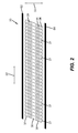
Fig. 2 is a schematic top view of the printhead ofFig. 1 showing a portion of the maintenance station; -
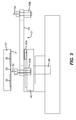
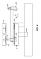
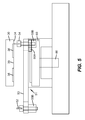
Figs. 3-5 are schematic side views of the printhead ofFig. 1 showing a wiping unit of the maintenance station moving from the parked position shown inFig. 1 through a partial wiping cycle of the printhead; -
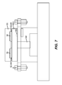
Figs. 6 and7 are schematic side views of the printhead ofFig. 1 showing a capping unit of the maintenance station moving from the parked position shown inFig. 1 to a capping position; -
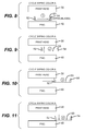
Figs. 8-15 are schematic side views of the printhead ofFig. 1 showing another example embodiment of a wiping unit of the maintenance station moving from a parked position through a complete wiping cycle of the printhead; -
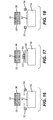
Figs. 16-18 are schematic side views of the printhead ofFig. 1 showing another example embodiment of a wiping unit of the maintenance station moving from a parked position through a complete wiping cycle of the printhead; -
Fig. 19 is a schematic top view of the printhead ofFig. 1 showing one of the wipers of the present invention; -
Fig. 20 is a schematic side view of an example embodiment of the wiper shown inFig. 19 ; and -
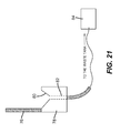
Fig. 21 is a schematic side view of an example embodiment of a wiper base. - The present description will be directed in particular to elements forming part of, or cooperating more directly with, apparatus in accordance with the present invention. It is to be understood that elements not specifically shown or described may take various forms well known to those skilled in the art.
- Referring to
Fig. 1 , a schematic side view of an example embodiment of the present invention showing aprinthead 30 and amaintenance station 40 in a parked position is shown.Printhead 30, extending into and out of the figure, is positioned overmaintenance station 40. Movement ofprinthead 30 is accomplished by translatingprinthead 30 along rails or tracks from a printing position over a print media to a position overmaintenance station 40 when it is time to perform a maintenance operation. However, other movement techniques known in the art can also be used. -
Maintenance station 40, also referred to as a purging wiping capping (PWC) station, includes awiping unit 50 and acapping unit 60.Wiping unit 50 includes afirst wiper 52 and asecond wiper 54.Wiping unit 50 andcapping unit 60 are supported by aframe structure 42 ofmaintenance station 40.Maintenance station 40, as shown inFig. 1 , is in a parked or home position so as to accommodate movement ofprinthead 30 tomaintenance station 40 and movement ofcapping unit 60 towardprinthead 30. - Typically, capping occurs before purging or prior to a temporary shut down of
printhead 30 while wiping occurs after purging. Purging helps to remove air bubbles that become trapped withinprinthead 30 during liquid, for example, ink, filling or changing operations; clean the liquid circuit; and recover failing jets. - Referring to
Fig. 2 , a schematic top view ofprinthead 30,first wiper 52, andsecond wiper 54 ofwiping unit 50 ofmaintenance station 40 are shown.Printhead 30 includes a plurality ofjetting modules 31 disposed side by side in a row (represented by arrow 32) and inclined relative to a direction of print media motion (represented by arrow 33). Each of the plurality ofjetting modules 31 includes anozzle face 34 with eachnozzle face 34 including afirst nozzle array 35 configured to eject a first liquid and asecond nozzle array 36 configured to eject a second liquid.First nozzle array 35 is supplied with the first liquid, for example, a first color ink, andsecond nozzle array 36 is supplied with the second liquid, for example, a second color ink, independently of the other. Ejection of the first liquid throughnozzle array 35 and ejection of the second liquid throughsecond nozzle array 36 is accomplished using known techniques, for example, by using a piezoelectric actuator(s) or a heater(s).First wiper 52 is associated withfirst nozzle array 35 of eachjetting module 31.Second wiper 54 is associated withsecond nozzle array 36 of eachjetting module 31. - The first liquid can be a first color ink and the second liquid can be a second color ink with the first and second colors being different from each other in some aspect, for example, color, density, and viscosity. Alternatively, first and second liquids can be any printing liquids that are distinct enough from each other such that it is preferable to separately desirable to separately maintain the nozzle arrays ejecting each liquid.
- In
Fig. 2 ,first nozzle array 35 includes two rows of nozzles positioned on afirst side 37 ofnozzle face 34 of jettingmodule 31 andsecond nozzle array 36 includes two rows of nozzles positioned on asecond side 38 ofnozzle face 34 of jettingmodule 31. Agap 39 exists betweenfirst nozzle array 35 andsecond nozzle array 36. - Referring to
Figs. 3-5 , schematic side views ofprinthead 30 and wipingunit 50 ofmaintenance station 40 moving from the parked position shown inFig. 1 through a partial wiping cycle ofprinthead 30 are shown. In addition tofirst wiper 52 andsecond wiper 54, wipingunit 50 includes awiper moving mechanism 51. -
Wiper moving mechanism 51 includes aframe 53 and an actuator(s) 55 that movefirst wiper 52 andsecond wiper 54 through a wiping cycle ofprinthead 30. The motion offirst wiper 52 andsecond wiper 54 is perpendicular and lateral to the nozzle face ofprinthead 30 and is provided by one or more conventional actuators 55, for example, a motor or solenoid appropriately linked or geared to wipingunit 50.Wiper moving mechanism 51 can include separate actuators 55 that accomplish lateral motion, actuator 55A, and perpendicular motion,actuator 55B. - Alternatively,
wiper moving mechanism 51 can include only alateral motion actuator 55A and use thevertical actuator 86 associated with the cappingunit 60 to provide perpendicular motion. This is accomplished by causing cappingunit 60 to contact the wipingunit 50 and then move vertically so thatfirst wiper 52 contacts printhead 30 as described above.Lateral motion actuator 55A then movesfirst wiper 52 across eachfirst nozzle array 35. The vertical actuator associated with the cappingunit 60 then lowers cappingunit 60 andfirst wiper 52. The process is then repeated withsecond wiper 54. -
First wiper 52 is disposed onwiper moving mechanism 51.First wiper 52 is caused bywiper moving mechanism 51 to move from its parked position (shown inFig. 1 ) to a location betweenfirst nozzle array 35 andsecond nozzle array 36 of each jettingmodule 31 and removed fromnozzle face 34 of each jetting module 31 (shown inFig. 3 ).Wiper moving mechanism 51 causesfirst wiper 52 to contact eachnozzle face 34 at a first location (gap 39) betweenfirst nozzle array 35 andsecond nozzle array 36 of each jetting module 31 (shown inFig. 4 ).First wiper 52 is then caused bywiper moving mechanism 51 to move acrossfirst nozzle array 35 of each jettingmodule 31 to a second location removed fromfirst nozzle array 35 of each jetting module 31 (shown inFig. 5 ).First wiper 52 then returns to its home or parked position (shown inFig. 1 ) without contactingfirst nozzle array 35. - The wiping cycle by
first wiper 52 offirst nozzle array 35 of each jettingmodule 31 is from the inside or center of each jettingmodule 31 to the outside edge of each jettingmodule 31. This wiping motion helps to reduce the likelihood of liquid accumulation in thegap 39 area ofnozzle face 34. The wiping cycle offirst nozzle array 35 byfirst wiper 52 is also shown in more detail with reference toFigs. 8-15 . -
Second wiper 54 is also disposed onwiper moving mechanism 51. Wiper moving mechanism causessecond wiper 54 to move from its parked position and contact eachnozzle face 34 at a third location (gap 39) betweenfirst nozzle array 35 andsecond nozzle array 36 of each jettingmodule 31.Second wiper 54 is then caused bywiper moving mechanism 51 to move acrosssecond nozzle array 36 of each jettingmodule 31 to a fourth location removed fromsecond nozzle array 36 of each jettingmodule 31. - The wiping cycle by
second wiper 54 ofsecond nozzle array 36 of each jettingmodule 31 is from the inside or center of each jettingmodule 31 to the outside edge of each jettingmodule 31. This wiping motion helps to reduce the likelihood of liquid accumulation in thegap 39 area ofnozzle face 34. The wiping cycle ofsecond nozzle array 36 bysecond wiper 54 is also shown in more detail with reference toFigs. 8-15 . - The second location removed from
first nozzle array 35 of each jettingmodule 31 is on one side of each jettingmodule 31 while the fourth location removed fromsecond nozzle array 36 of each jettingmodule 31 is on another side of each jettingmodule 31.Second wiper 54 then returns to its home or parked position (shown inFig. 1 ) without contactingsecond nozzle array 36. - The wiping cycle by
first wiper 52 offirst nozzle array 35 is considered to be in a direction opposite that of the wiping cycle direction ofsecond nozzle array 36 bysecond wiper 54. - Referring to
Figs. 6 and7 , schematic side views ofprinthead 30 andcapping unit 60 ofmaintenance station 40 moving from the parked position shown inFig. 1 to a capping position are shown. Cappingunit 60 includes a plurality of cap pairs 62 corresponding to the plurality of jettingmodules 31 with one cap 64 of each cap pair 62 associated withfirst nozzle array 35 of thecorresponding jetting module 31 and the other cap 66 of the cap pair 62 associated withsecond nozzle array 36 of thecorresponding jetting module 31. Cappingunit 60 is moveable betweenfirst wiper 52 andsecond wiper 54 to a first position in which each of the plurality of cap pairs 62 is in a sealing contact withfirst nozzle array 35 andsecond nozzle array 36 of thecorresponding jetting module 31 and a second position removed from contact withfirst nozzle array 35 andsecond nozzle array 36 of thecorresponding jetting module 31. The motion of cappingunit 60 is perpendicular toprinthead 30 and is provided by aconventional actuator 86, for example, a motor or solenoid appropriately linked or geared to cappingunit 60. - A gasket made from a suitable compliant material, for example, rubber, can be provided with each cap 64 and 66 to help provide a fluidic seal with
first nozzle array 35 andsecond nozzle array 36 of thecorresponding jetting module 31. Each cap 64 and 66 or each cap pair 62 can be mounted on a spring which helps to maintain the fluidic seal withfirst nozzle array 35 andsecond nozzle array 36 of thecorresponding jetting module 31. - Each cap 64, 66 of the plurality of cap pairs 62 includes a base 68 with an
opening 69.Opening 69 is in fluid communication, for example, through a tube, with a waste tank (not shown) to allow for evacuation of liquid throughopening 69. During capping, vacuum can be applied to each cap 64, 66 of each cap pair 62 using a puck to help suck liquid away from eachfirst nozzle array 35 andsecond nozzle array 36. - When capping
unit 60 is in contact with jettingmodules 31, purging can occur. Purging can include providing a back pressure at the meniscus of the first liquid and the second liquid causing the liquids to be expelled fromprinthead 30 while each of the plurality of cap pairs 62 is in contact with thefirst nozzle array 35 andsecond nozzle array 36 of thecorresponding jetting module 31 ofprinthead 30. The sequence of jettingmodule 31 purging can include purging each jettingmodule 31 individually, purging groups of jettingmodules 31 in succession, or purging all of the jettingmodules 31 simultaneously. - Wiping can occur after capping
unit 60 is removed from jettingmodules 31. Wiping can include providing a positive pressure at the meniscus of the first liquid and the second liquid which helps to expel the liquids during this operation. Applying a negative pressure at the meniscus of the first liquid and the second liquid which helps to draw the liquids back into each nozzle after the wiping operation is complete. - Referring to
Figs. 8-15 , schematic side views ofprinthead 30 and another example embodiment of wipingunit 50 ofmaintenance station 40 moving from a parked position through a complete wiping cycle ofprinthead 30 are shown. In these figures,printhead 30 extends into and out of the figure.Wiper moving mechanism 51 includes amoveable frame 53 to whichfirst wiper 52 andsecond wiper 54 are affixed. In thisframe 53 configuration,first wiper 52 andsecond wiper 54 move laterally as a unit.Frame 53 includes an opening through which cappingunit 60 passes through when moving from its parked position to a capping position. - Initially, wiping
unit 50 is at its home position (position 1 inFig. 8 ). Wipingunit 50 moves laterally to positionfirst wiper 52 betweenfirst nozzle array 35 andsecond nozzle array 36 of eachcorresponding jetting module 31. Wipingunit 50 moves vertically so thatfirst wiper 52 contacts each nozzle face 34 (position 2 inFig. 9 ).First wiper 52 moves acrossfirst nozzle array 35 of each jettingmodule 31 while maintaining contact with each first nozzle array 35 (position 3 inFig. 10 ).First wiper 52 then moves away fromfirst nozzle array 35 of each jettingmodule 31 towardframe 42 ofmaintenance station 40 to a location removed fromfirst nozzle array 35 of each jetting module 31 (position 4 inFig. 11 ). - Next, wiping
unit 50 moves laterally in an opposite direction to positionsecond wiper 54 betweenfirst nozzle array 35 andsecond nozzle array 36 of each corresponding jetting module 31 (position 5 inFig. 12 ). Wipingunit 50 then moves vertically so thatsecond wiper 54 contacts each nozzle face 34 (position 6 inFig. 13 ).Second wiper 54 moves acrosssecond nozzle array 36 of each jettingmodule 31 while maintaining contact with each second nozzle array 36 (position 7 inFig. 14 ).Second wiper 54 then moves away fromsecond nozzle array 36 of each jettingmodule 31 towardframe 42 ofmaintenance station 40 to a location removed fromfirst nozzle array 35 of each jetting module 31 (position 8 inFig. 15 ), ultimately,wiper unit 50 returns to its home position (position 1 inFig. 8 ). - Referring to
Figs. 16-18 , schematic side views ofprinthead 30 and another example embodiment of awiping unit 50 ofmaintenance station 40 moving from a parked position through a complete wiping cycle ofprinthead 30 are shown. In this example embodiment,first wiper 52 andsecond wiper 54 move from a home position (Fig, 16 ) to a location betweenfirst nozzle array 35 and second nozzle array 36 (Fig. 17 ). The movement offirst wiper 52 andsecond wiper 54 can occur either in series or in parallel.First wiper 52 wipesfirst nozzle array 35 andsecond wiper 54 wipessecond nozzle array 36 as described above. After the wiping cycle is complete,first wiper 52 andsecond wiper 54 return to their respective home positions. - Referring to
Fig. 19 , a schematic top view ofprinthead 30 andfirst wiper 52 is shown. And, referring toFig. 20 , a schematic side view of an example embodiment offirst wiper 52, also shown inFig. 19 , is shown.First wiper 52 is positioned parallel to the row of jettingmodules 31.Second wiper 54 can also be positioned in the same manner. First wiper 52 (and second wiper 54) are moveable in the direction of the inclination of the plurality of jettingmodules 31 bywiper moving mechanism 51. First wiper 52 (and second wiper 54) is ablade type 76 wiper that continuously spans the length ofprinthead 30. - Optionally, first wiper 52 (and second wiper 54) includes a plurality of
wiper blades 70 that span the row of jettingmodules 31. Additionally, or alternatively, first wiper 52 (and second wiper 54) includes a segmented or notchedwiper blade 72 with eachsegment 74 being contactable only with the first nozzle array 35 (second nozzle array 36) of thecorresponding jetting module 31. Eachsegment 74 of segmentedwiper blade 72 can be positioned parallel to the row of jettingmodules 31. Additionally, notch 73 is positioned in the areas between first nozzle arrays 35 (second nozzles arrays 36) so as to minimize liquid accumulation in these areas during wiping.Wiper blades nozzle face 34. Typically,wiper blades - Referring to
Fig. 21 , a schematic side view of an example embodiment of a wiper base is shown. In this embodiment,first wiper 52 includes ablade type wiper 76 affixed to awiper blade base 78.Wiper blade base 78 includes acatch basin 80 to collect liquid fromwiper 76.Catch basin 80 leads to adrain 82 that is in fluid communication with awaste tank 84.Catch basin 80 spans the length ofwiper base 76. However, other configurations ofcatch basin 80 are permitted and depend on the specific type of wiper being used. - The invention has been described in detail with particular reference to certain preferred embodiments thereof, but it will be understood that variations and modifications can be effected within the scope of the invention.
-
- 1. A maintenance station apparatus for a printhead including a plurality of jetting modules disposed side by side in a row and inclined relative to a direction of print media motion, each of the plurality of jetting modules including a nozzle face, each nozzle face including a first nozzle array configured to eject a first liquid and a second nozzle array configured to eject a second liquid, the maintenance station apparatus comprising:
- a wiping unit including a first wiper, a second wiper, and a wiper moving mechanism, the first wiper being associated with the first nozzle array of each jetting module and the second wiper being associated with the second nozzle array of each jetting module, the first wiper being disposed on the wiper moving mechanism such that the first wiper contacts each nozzle face at a first location between the first nozzle array and the second nozzle array of each jetting module and moves across the first nozzle array of each jetting module to a second location removed from the first nozzle array of each jetting module, the second wiper being disposed on the wiper moving mechanism such that the second wiper contacts each nozzle face at a third location between the first nozzle array and the second nozzle array of each jetting module and moves across the second nozzle array of each jetting module to a fourth location removed from the second nozzle array of each jetting module; and
- a capping unit including a plurality of cap pairs corresponding to the plurality of jetting modules, one cap of each cap pair being associated with the first nozzle array of the corresponding jetting module, the other cap of the cap pair being associated with the second nozzle array of the corresponding jetting module, the capping unit being moveable between the first wiper and the second wiper to a first position in which each of the plurality of cap pairs is in contact with the first nozzle array and second nozzle array of the corresponding jetting module and a second position removed from contact with the first nozzle array and second nozzle array of the corresponding jetting module.
- 2. The apparatus as in 1, wherein the wiper moving mechanism includes a moveable frame to which the first wiper and the second wiper are affixed such that the first wiper and the second wiper move laterally as a unit.
- 3. The apparatus as in 2, wherein the moveable frame includes an opening, the capping unit being moveable through the opening of the frame.
- 4. The apparatus as in 1, wherein the first wiper includes a plurality of wiper blades that span the row of jetting modules.
- 5. The apparatus as in 1, wherein the first wiper includes a segmented wiper blade, each segment being contactable only with the first nozzle array of the corresponding jetting module.
- 6. The apparatus as in 5, wherein each segment of the segmented wiper blade is positioned parallel to the row of jetting modules.
- 7. The apparatus as in 1, wherein first wiper and the second wiper are moveable in the direction of the inclination of the plurality of jetting modules.
- 8. The apparatus as in 1, wherein each cap of the plurality of cap pairs includes a base with an opening, the opening being in fluid communication with a waste tank to allow for evacuation of liquid through the opening.
- 9. The apparatus as in 1, wherein the first liquid is a first color ink and the second liquid is a second color ink.
- 10. A method of maintaining a printhead including a plurality of jetting modules disposed side by side in a row and inclined relative to a direction of print media motion, each of the plurality of jetting modules including a nozzle face, each nozzle face including a first nozzle array configured to eject a first liquid and a second nozzle array configured to eject a second liquid, the method comprising:
- providing a wiping unit including a first wiper, a second wiper, and a wiper moving mechanism, the first wiper being associated with the first nozzle array of each jetting module and the second wiper being associated with the second nozzle array of each jetting module, the first wiper being disposed on the wiper moving mechanism, the second wiper being disposed on the wiper moving mechanism;
- causing the first wiper to contact each nozzle face at a first location between the first nozzle array and the second nozzle array of each jetting module;
- moving the first wiper across the first nozzle array of each jetting module to a second location removed from the first nozzle array of each jetting module;
- causing the second wiper to contact each nozzle face at a third location between the first nozzle array and the second nozzle array of each jetting module; and
- moving the second wiper across the second nozzle array of each jetting module to a fourth location removed from the second nozzle array of each jetting module.
- 11. The method as in 10, further comprising:
- providing a capping unit including a plurality of cap pairs corresponding to the plurality of jetting modules, one cap of each cap pair being associated with the first nozzle array of the corresponding jetting module, the other cap of the cap pair being associated with the second nozzle array of the corresponding jetting module; and
- causing the capping unit to move between the first wiper and the second wiper to a first position in which each of the plurality of cap pairs is in contact with the first nozzle array and second nozzle array of the corresponding jetting module and a second position removed from contact with the first nozzle array and second nozzle array of the corresponding jetting module.
- 12. The method as in 11, further comprising:
- purging the printhead of the first liquid and the second liquid by applying a vacuum to the capping unit while each of the plurality of cap pairs is in contact with the first nozzle array and second nozzle array of the corresponding jetting module of the printhead.
- 13. The method as in 12, further comprising:
- purging the printhead of the first liquid and the second liquid while each of the plurality of cap pairs is in contact with the first nozzle array and second nozzle array of the corresponding jetting module of the printhead.
-
- 30
- printhead
- 31
- plurality of jetting modules
- 32
- arrow
- 33
- arrow
- 34
- nozzle face
- 35
- first nozzle array
- 36
- second nozzle array
- 37
- first side
- 38
- second side
- 39
- gap
- 40
- maintenance station
- 42
- frame structure
- 51
- wiper moving mechanism
- 52
- first wiper
- 53
- frame
- 54
- second wiper
- 55
- actuator(s)
- 62
- plurality of cap pairs
- 64
- one cap
- 66
- other cap
- 68
- base
- 69
- opening
- 70
- plurality of wiper blades
- 72
- segmented wiper blade
- 74
- each segment
- 76
- blade type wiper
- 78
- wiper blade base
- 82
- drain
- 84
- waste tank
- 86
- actuator
Claims (7)
- A maintenance station apparatus for a printhead including a nozzle face having a nozzle array, the maintenance station apparatus comprising:a wiping unit including a first wiper, a second wiper, and a wiper moving mechanism, the first wiper being disposed on the wiper moving mechanism, the second wiper being disposed on the wiper moving mechanism; anda capping unit, the capping unit being moveable between the first wiper and the second wiper to a first position and moveable between the first wiper and the second wiper to a second position.
- The apparatus according to claim 1, wherein the wiper moving mechanism includes a moveable frame to which the first wiper and the second wiper are affixed such that the first wiper and the second wiper move laterally as a unit.
- The apparatus according to claim 2, wherein the moveable frame includes an opening, the capping unit being moveable through the opening of the frame.
- The apparatus according to claim 1, wherein the first wiper includes a plurality of wiper blades.
- The apparatus according to claim 1, wherein the first wiper includes a segmented wiper blade.
- The apparatus according to claim 1, wherein the first wiper and the second wiper move laterally, the lateral movement of first wiper and second wiper occurs either in series or in parallel.
- The apparatus according to claim 1, wherein the capping unit includes a base with an opening, the opening being in fluid communication with a waste tank to allow for evacuation of liquid through the opening.
Applications Claiming Priority (1)
| Application Number | Priority Date | Filing Date | Title |
|---|---|---|---|
| EP08157149A EP2127881B1 (en) | 2008-05-29 | 2008-05-29 | Multicolor printhead maintenance station |
Related Parent Applications (1)
| Application Number | Title | Priority Date | Filing Date |
|---|---|---|---|
| EP08157149.9 Division | 2008-05-29 |
Publications (1)
| Publication Number | Publication Date |
|---|---|
| EP2353869A1 true EP2353869A1 (en) | 2011-08-10 |
Family
ID=39873974
Family Applications (3)
| Application Number | Title | Priority Date | Filing Date |
|---|---|---|---|
| EP10157983A Ceased EP2202077B1 (en) | 2008-05-29 | 2008-05-29 | Multicolor printhead maintenance station |
| EP11162163A Withdrawn EP2353869A1 (en) | 2008-05-29 | 2008-05-29 | Multicolor printhead maintenance station |
| EP08157149A Ceased EP2127881B1 (en) | 2008-05-29 | 2008-05-29 | Multicolor printhead maintenance station |
Family Applications Before (1)
| Application Number | Title | Priority Date | Filing Date |
|---|---|---|---|
| EP10157983A Ceased EP2202077B1 (en) | 2008-05-29 | 2008-05-29 | Multicolor printhead maintenance station |
Family Applications After (1)
| Application Number | Title | Priority Date | Filing Date |
|---|---|---|---|
| EP08157149A Ceased EP2127881B1 (en) | 2008-05-29 | 2008-05-29 | Multicolor printhead maintenance station |
Country Status (5)
| Country | Link |
|---|---|
| US (1) | US8591001B2 (en) |
| EP (3) | EP2202077B1 (en) |
| JP (1) | JP5306454B2 (en) |
| CN (1) | CN102046386B (en) |
| WO (1) | WO2009144212A1 (en) |
Cited By (1)
| Publication number | Priority date | Publication date | Assignee | Title |
|---|---|---|---|---|
| CN106808610A (en) * | 2015-12-01 | 2017-06-09 | 科倍隆有限公司 | Method for preparing styrene-acrylonitrile melt |
Families Citing this family (12)
| Publication number | Priority date | Publication date | Assignee | Title |
|---|---|---|---|---|
| JP5785701B2 (en) * | 2010-08-10 | 2015-09-30 | 株式会社ミヤコシ | Wiping method of line head |
| DE102010036957B4 (en) | 2010-08-12 | 2013-07-11 | OCé PRINTING SYSTEMS GMBH | Staggered printhead printing apparatus and method of setting up this printing apparatus |
| JP5668918B2 (en) * | 2010-11-18 | 2015-02-12 | セイコーエプソン株式会社 | Liquid ejecting apparatus and method for wiping nozzle forming surface of liquid ejecting head |
| CN103587241B (en) * | 2013-11-05 | 2016-08-17 | 郑州新世纪数码打印科技有限公司 | Ink-stack bidirectional-movemealignment alignment device for double nozzles |
| CN104191820B (en) * | 2014-09-15 | 2016-08-17 | 郑州新世纪数码打印科技有限公司 | A kind of autonomous lifting type nozzle cleaning mechanism |
| JP6682198B2 (en) * | 2015-05-22 | 2020-04-15 | キヤノン株式会社 | Liquid ejecting apparatus, imprint apparatus, and method of manufacturing component |
| CN105798018B (en) * | 2016-03-30 | 2019-07-09 | 广东正业科技股份有限公司 | Cleaning device and cleaning process for spray head |
| US10046566B2 (en) * | 2016-08-02 | 2018-08-14 | Xerox Corporation | System for cleaning components used to clean inkjet printheads in inkjet printers |
| US9676196B1 (en) | 2016-08-02 | 2017-06-13 | Xerox Corporation | Wiper system for cleaning inkjet printheads in inkjet printers |
| USD905740S1 (en) | 2017-09-25 | 2020-12-22 | Xerox Corporation | Printer machine user interface screen with a set of icons |
| CN109703198B (en) * | 2017-10-25 | 2020-12-29 | 北大方正集团有限公司 | Printing head cleaning system and printing head cleaning method |
| US10894411B2 (en) * | 2019-02-11 | 2021-01-19 | Xerox Corporation | Cap and application devices stabilizing ink in nozzles of inkjet printheads |
Citations (5)
| Publication number | Priority date | Publication date | Assignee | Title |
|---|---|---|---|---|
| EP0799135A1 (en) | 1994-11-21 | 1997-10-08 | Techniku B.V. | Cleaning and sealing station for a printing head |
| US20030081053A1 (en) * | 2001-10-30 | 2003-05-01 | Barinaga John A. | Printing mechanism service station for a printbar assembly |
| US20040174410A1 (en) * | 2003-03-07 | 2004-09-09 | Chiung-Lun Wu | [a service station] |
| US20060146088A1 (en) * | 2005-01-04 | 2006-07-06 | Brian Schick | Ink jet printer service station having a selector valve |
| WO2007077597A1 (en) * | 2005-12-28 | 2007-07-12 | Sharp Kabushiki Kaisha | Droplet applicator |
Family Cites Families (23)
| Publication number | Priority date | Publication date | Assignee | Title |
|---|---|---|---|---|
| US5040000A (en) | 1988-05-12 | 1991-08-13 | Canon Kabushiki Kaisha | Ink jet recording apparatus having a space saving ink recovery system |
| US5602573A (en) * | 1993-04-30 | 1997-02-11 | Hewlett-Packard Company | Service station for inkjet printer having wipers with concave wiping edges |
| US5984450A (en) * | 1995-03-06 | 1999-11-16 | Hewlett-Packard Company | Inkjet printer having multiple printheads and multiple independent printhead service stations for performing different wiping procedures |
| JP3768633B2 (en) * | 1997-02-14 | 2006-04-19 | キヤノン株式会社 | Inkjet cartridge and printing apparatus |
| DE19726643C1 (en) | 1997-06-18 | 1998-07-23 | Francotyp Postalia Gmbh | Arrangement for cleaning an ink print head |
| JP2001071515A (en) * | 1999-09-08 | 2001-03-21 | Seiko Epson Corp | Printing equipment |
| US6460968B1 (en) * | 2000-06-14 | 2002-10-08 | Hewlett-Packard Company | Wiper for inkjet printers |
| AUPR399601A0 (en) * | 2001-03-27 | 2001-04-26 | Silverbrook Research Pty. Ltd. | An apparatus and method(ART108) |
| US6929347B2 (en) * | 2001-04-24 | 2005-08-16 | Canon Kabushiki Kaisha | Ink jet printing apparatus and wiping method therefor |
| JP2003001855A (en) * | 2001-06-21 | 2003-01-08 | Olympus Optical Co Ltd | Recovery device for inkjet printer |
| FR2832941B1 (en) | 2001-11-30 | 2004-09-24 | Gemplus Card Int | CLEANING MATERIAL JET HEADS |
| JP3943997B2 (en) * | 2002-06-07 | 2007-07-11 | キヤノン株式会社 | Inkjet recording device |
| US6843550B2 (en) * | 2003-04-22 | 2005-01-18 | Hewlett-Packard Development Company, L.P. | Printhead servicing mechanism and method |
| US7210761B2 (en) * | 2003-09-23 | 2007-05-01 | Hewlett-Packard Development Company, L.P. | Wiper apparatus and method for cleaning a printhead |
| US7029093B2 (en) * | 2003-12-19 | 2006-04-18 | Hewlett-Packard Development Company, L.P. | Modular service station assembly |
| US7001009B2 (en) * | 2004-01-20 | 2006-02-21 | Brother Kogyo Kabushiki Kaisha | Recording apparatus having wiping device |
| JP4222234B2 (en) * | 2004-03-17 | 2009-02-12 | セイコーエプソン株式会社 | Liquid ejector |
| US7390074B2 (en) * | 2004-05-07 | 2008-06-24 | Natsushita Electric Industrial Co., Ltd. | Methods of and apparatuses for wiping a line head in an ink jet recorder |
| KR100644651B1 (en) | 2004-11-19 | 2006-11-10 | 삼성전자주식회사 | Inkjet printer |
| KR100694121B1 (en) * | 2005-06-02 | 2007-03-12 | 삼성전자주식회사 | Inkjet image forming apparatus and nozzle cleaning method |
| US7766450B2 (en) * | 2005-09-16 | 2010-08-03 | Brother Kogyo Kabushiki Kaisha | Ink jet recording apparatus |
| JP2007203557A (en) * | 2006-01-31 | 2007-08-16 | Ricoh Co Ltd | Droplet discharge device |
| US20090179942A1 (en) * | 2008-01-16 | 2009-07-16 | Silverbrook Research Pty Ltd | Printhead maintenance facility with nozzle wiper movable parallel to media feed direction |
-
2008
- 2008-05-29 EP EP10157983A patent/EP2202077B1/en not_active Ceased
- 2008-05-29 EP EP11162163A patent/EP2353869A1/en not_active Withdrawn
- 2008-05-29 EP EP08157149A patent/EP2127881B1/en not_active Ceased
-
2009
- 2009-05-26 WO PCT/EP2009/056356 patent/WO2009144212A1/en not_active Ceased
- 2009-05-26 US US12/993,339 patent/US8591001B2/en active Active
- 2009-05-26 CN CN200980119855.3A patent/CN102046386B/en not_active Expired - Fee Related
- 2009-05-26 JP JP2011510982A patent/JP5306454B2/en not_active Expired - Fee Related
Patent Citations (6)
| Publication number | Priority date | Publication date | Assignee | Title |
|---|---|---|---|---|
| EP0799135A1 (en) | 1994-11-21 | 1997-10-08 | Techniku B.V. | Cleaning and sealing station for a printing head |
| US20030081053A1 (en) * | 2001-10-30 | 2003-05-01 | Barinaga John A. | Printing mechanism service station for a printbar assembly |
| US20040174410A1 (en) * | 2003-03-07 | 2004-09-09 | Chiung-Lun Wu | [a service station] |
| US20060146088A1 (en) * | 2005-01-04 | 2006-07-06 | Brian Schick | Ink jet printer service station having a selector valve |
| WO2007077597A1 (en) * | 2005-12-28 | 2007-07-12 | Sharp Kabushiki Kaisha | Droplet applicator |
| EP1972385A1 (en) * | 2005-12-28 | 2008-09-24 | Sharp Kabushiki Kaisha | Droplet applicator |
Cited By (2)
| Publication number | Priority date | Publication date | Assignee | Title |
|---|---|---|---|---|
| CN106808610A (en) * | 2015-12-01 | 2017-06-09 | 科倍隆有限公司 | Method for preparing styrene-acrylonitrile melt |
| CN106808610B (en) * | 2015-12-01 | 2021-06-04 | 科倍隆有限公司 | Method for producing a styrene-acrylonitrile melt |
Also Published As
| Publication number | Publication date |
|---|---|
| JP5306454B2 (en) | 2013-10-02 |
| EP2202077A1 (en) | 2010-06-30 |
| US20120176446A1 (en) | 2012-07-12 |
| EP2127881B1 (en) | 2011-11-23 |
| JP2011530424A (en) | 2011-12-22 |
| EP2202077B1 (en) | 2011-06-22 |
| CN102046386A (en) | 2011-05-04 |
| EP2127881A1 (en) | 2009-12-02 |
| CN102046386B (en) | 2013-08-21 |
| WO2009144212A1 (en) | 2009-12-03 |
| US8591001B2 (en) | 2013-11-26 |
Similar Documents
| Publication | Publication Date | Title |
|---|---|---|
| EP2127881B1 (en) | Multicolor printhead maintenance station | |
| JP5259458B2 (en) | Inkjet recording apparatus and recording head maintenance method | |
| WO2001087623A1 (en) | Service station for inkjet printheads | |
| US20090147043A1 (en) | Inkjet printer comprising integrated capper and cleaner | |
| JP6597650B2 (en) | Inkjet recording device | |
| US8147031B2 (en) | Recording apparatus | |
| US20090309918A1 (en) | Fluid ejecting apparatus | |
| JP5347324B2 (en) | Inkjet recording device | |
| US20180194139A1 (en) | Liquid ejecting apparatus | |
| US20090147042A1 (en) | Microcapping of inkjet nozzles | |
| US9421778B2 (en) | Liquid discharge apparatus | |
| US9550363B2 (en) | Ink-jet recording apparatus | |
| JP2009178848A (en) | Recording device | |
| US20090147044A1 (en) | Pressure capping of inkjet nozzles | |
| CN101274527A (en) | inkjet recording device | |
| JP2018118441A (en) | Recording head recovery system and ink jet recording apparatus including the same | |
| JP4970229B2 (en) | Inkjet printer cleaning device | |
| JP6221946B2 (en) | RECOVERY SYSTEM OF PRINT HEAD, INKJET RECORDING DEVICE EQUIPPED WITH THE SAME, AND RECOVERY METHOD OF RECORD HEAD | |
| JP6340924B2 (en) | RECOVERY SYSTEM OF PRINT HEAD, INKJET RECORDING DEVICE EQUIPPED WITH THE SAME, AND RECOVERY METHOD OF RECORD HEAD | |
| JP2007130806A (en) | Inkjet recording device | |
| JP2010046855A (en) | Fluid ejection device and maintenance method | |
| JP2018114666A (en) | Head cleaning mechanism and ink jet recording apparatus having the same | |
| JP2019018355A (en) | Recording head and ink jet recording apparatus provided with the same | |
| JP4582016B2 (en) | Inkjet recording device | |
| JP2016055467A (en) | RECOVERY SYSTEM OF PRINT HEAD, INKJET RECORDING DEVICE EQUIPPED WITH THE SAME, AND RECOVERY METHOD OF RECORD HEAD |
Legal Events
| Date | Code | Title | Description |
|---|---|---|---|
| PUAI | Public reference made under article 153(3) epc to a published international application that has entered the european phase |
Free format text: ORIGINAL CODE: 0009012 |
|
| AC | Divisional application: reference to earlier application |
Ref document number: 2127881 Country of ref document: EP Kind code of ref document: P |
|
| AK | Designated contracting states |
Kind code of ref document: A1 Designated state(s): DE FR GB NL |
|
| STAA | Information on the status of an ep patent application or granted ep patent |
Free format text: STATUS: THE APPLICATION IS DEEMED TO BE WITHDRAWN |
|
| 18D | Application deemed to be withdrawn |
Effective date: 20120211 |