JP5668918B2 - Liquid ejecting apparatus and method for wiping nozzle forming surface of liquid ejecting head - Google Patents
Liquid ejecting apparatus and method for wiping nozzle forming surface of liquid ejecting head Download PDFInfo
- Publication number
- JP5668918B2 JP5668918B2 JP2010258159A JP2010258159A JP5668918B2 JP 5668918 B2 JP5668918 B2 JP 5668918B2 JP 2010258159 A JP2010258159 A JP 2010258159A JP 2010258159 A JP2010258159 A JP 2010258159A JP 5668918 B2 JP5668918 B2 JP 5668918B2
- Authority
- JP
- Japan
- Prior art keywords
- wiper
- wiping
- liquid
- liquid ejecting
- nozzle
- Prior art date
- Legal status (The legal status is an assumption and is not a legal conclusion. Google has not performed a legal analysis and makes no representation as to the accuracy of the status listed.)
- Active
Links
Images


Description
本発明は、ノズル形成面に、第1の液を吐出する第1のノズル列と、第2の液を吐出する第2のノズル列とが被液体噴射材の搬送方向と交差する方向に並設されている液体噴射ヘッドと、前記ノズル形成面を払拭するワイパーを前記ノズル形成面に対して進退可能に備える払拭装置とを備えた液体噴射装置及び液体噴射ヘッドのノズル形成面の払拭方法に関するものである。 According to the present invention, the first nozzle row for discharging the first liquid and the second nozzle row for discharging the second liquid are arranged on the nozzle forming surface in a direction intersecting with the transport direction of the liquid ejecting material. The present invention relates to a liquid ejecting apparatus comprising: a liquid ejecting head provided; and a wiping device including a wiper that wipes the nozzle forming surface with respect to the nozzle forming surface; and a method for wiping the nozzle forming surface of the liquid ejecting head. Is.
被液体噴射材の一例である用紙上に反応液となる第1の液を噴射してプレコート層を形成し、該プレコート層上に被反応液となる第2の液を噴射することで被液体噴射材上で凝集物を形成して画質の向上を図ることがインクジェットプリンター等の液体噴射装置で実施されている。
この場合、製品コストや収容スペースの関係で同一の液体噴射ヘッドのノズル形成面に前記第1の液を吐出する第1のノズル列と、第2の液を吐出する第2のノズル列とが設けられている。
A pre-coating layer is formed by ejecting a first liquid as a reaction liquid onto a sheet, which is an example of a liquid ejecting material, and a second liquid as a reacting liquid is ejected onto the pre-coating layer. 2. Description of the Related Art Forming aggregates on a jetting material to improve image quality is performed by a liquid jetting apparatus such as an ink jet printer.
In this case, a first nozzle row that discharges the first liquid and a second nozzle row that discharges the second liquid on the nozzle formation surface of the same liquid jet head due to product cost and storage space. Is provided.
この構造は、前記ノズル形成面をワイパー等によって拭き取って液体吐出ノズルの動作回復を行う時に、該ノズル形成面上で前記第1の液と第2の液が混ざることによって凝集物が生成される問題がある。この凝集物は液体吐出ノズルからの液体の吐出を妨げ、画質低下の原因となる。
下記の特許文献1には、上記のようにしてノズル形成面上で生成された凝集物がノズル形成面を傷付けないようにする観点で、ワイドブレードと抑止板とを備える2枚構成のワイパーと、ノズル形成面と前記2枚のワイパーによって囲まれた空間に洗浄液を供給する構造が開示されている。
In this structure, when the operation of the liquid discharge nozzle is recovered by wiping the nozzle forming surface with a wiper or the like, an aggregate is generated by mixing the first liquid and the second liquid on the nozzle forming surface. There's a problem. This agglomerate prevents the liquid from being ejected from the liquid ejection nozzle and causes a reduction in image quality.
In the following
しかし、前記特許文献1に開示されている構造では、ノズル形成面上で反応し生成された凝集物を完全に除去できない。そのため、吐出ノズルの正常な動作が前記凝集物によって妨げられる問題がある。
However, the structure disclosed in
本発明の目的は、第1の液を吐出する第1のノズル列と、第2の液を吐出する第2のノズル列とが同一のノズル形成面に設けられている液体噴射ヘッドにおいて、該ノズル形成面をワイパーで払拭する際に、前記第1の液と第2の液が同一のノズル形成面上で混ざることによって生成される凝集物の発生を防止することにある。 An object of the present invention is to provide a liquid ejecting head in which a first nozzle row for discharging a first liquid and a second nozzle row for discharging a second liquid are provided on the same nozzle forming surface. When the nozzle forming surface is wiped with a wiper, the first liquid and the second liquid are prevented from being generated on the same nozzle forming surface.
本発明の第1の態様に係る液体噴射装置は、ノズル形成面に、第1の液を吐出する第1のノズル列と、第2の液を吐出する第2のノズル列とが被液体噴射材の搬送方向と交差する方向に並設されている液体噴射ヘッドと、前記ノズル形成面を払拭するワイパーを前記ノズル形成面に対して進退可能に備える払拭装置と、前記ワイパーの進退動作と、該ワイパーと前記液体噴射ヘッドの前記交差方向における相対移動動作とを組み合せて実行される払拭動作を制御する制御部とを備える液体噴射装置であって、前記制御部は、前記ワイパーが前記第1のノズル列と第2のノズル列との間の位置を払拭開始位置として該払拭開始位置に前記ワイパーを接触させ、前記相対移動の一方向への移動によって該一方向の払拭を実行し、次いで前記ワイパーを前記払拭開始位置に再度接触させ、前記相対移動の他方向への移動によって該他方向の払拭を実行するように構成されていることを特徴とするものである。 In the liquid ejecting apparatus according to the first aspect of the present invention, the first nozzle row for ejecting the first liquid and the second nozzle row for ejecting the second liquid are ejected on the nozzle forming surface. A liquid ejecting head arranged in parallel in a direction intersecting the conveying direction of the material, a wiping device provided with a wiper for wiping the nozzle forming surface so as to be able to advance and retreat with respect to the nozzle forming surface, and a forward and backward movement of the wiper, A liquid ejecting apparatus comprising: a control unit that controls a wiping operation that is performed by combining the wiper and a relative movement operation of the liquid ejecting head in the intersecting direction, wherein the control unit is configured such that the wiper includes the first wiper. The wiper is brought into contact with the wiping start position with the position between the nozzle row and the second nozzle row as the wiping start position, and the wiping in one direction is performed by moving the relative movement in one direction, The wiper Contacting again the wiping start position, and is characterized in that it is configured to perform wiping of the other direction by the movement in the other direction of the relative movement.
本態様によれば、液体噴射ヘッドの吐出ノズルの動作を回復させるために行うワイパーによる払拭動作を、ノズル形成面に備えられている第1のノズル列と第2のノズル列の間の払拭開始位置からスタートして前記相対移動方向における一方向と他方向に向けてそれぞれ行うことになる。従って、前記払拭動作中に前記ワイパーが第1のノズル列と第2のノズル列の両方を横切って移動することがないので、第1の液と第2の液がノズル形成面上で混ざることがない。これによりノズル形成面での凝集物の生成が防止される。 According to this aspect, the wiping operation by the wiper performed to recover the operation of the discharge nozzle of the liquid ejecting head is started between the first nozzle row and the second nozzle row provided on the nozzle forming surface. Starting from the position, it is performed in one direction and the other direction in the relative movement direction. Therefore, since the wiper does not move across both the first nozzle row and the second nozzle row during the wiping operation, the first liquid and the second liquid are mixed on the nozzle formation surface. There is no. Thereby, the production | generation of the aggregate on a nozzle formation surface is prevented.
ここで、前記ワイパーと前記液体噴射ヘッドの相対移動は、前記ワイパーの前記払拭開始位置を通る前記液体噴射ヘッドの移動によって行える。 Here, the relative movement of the wiper and the liquid ejecting head can be performed by the movement of the liquid ejecting head passing through the wiping start position of the wiper.
これにより、前記ワイパーと前記液体噴射ヘッドの相対移動を、既存の液体噴射ヘッドの移動構造を利用して行うことができるので、ワイパーについては、進退機構(昇降機構)を設けるだけの簡単な構成によって払拭動作を実行することが可能になる。 As a result, the relative movement between the wiper and the liquid ejecting head can be performed by using the existing moving structure of the liquid ejecting head, so that the wiper has a simple configuration in which only an advance / retreat mechanism (elevating mechanism) is provided. By this, it becomes possible to execute the wiping operation.
また、前記ワイパーと前記液体噴射ヘッドの相対移動は、ワイパーを前記相対移動の方向に移動可能に構成し、前記ワイパーの前記払拭開始位置を通る移動によって行える。 Further, the relative movement between the wiper and the liquid ejecting head can be performed by moving the wiper in the direction of the relative movement and moving the wiper through the wiping start position.
これにより、前記ワイパーと前記液体噴射ヘッドの相対移動を、既存の液体噴射ヘッドの移動態様を変更することなく、進退可能(昇降可能)なワイパーの前記相対方向への移動によって払拭動作を実行することが可能になる。 Accordingly, the wiping operation is executed by moving the wiper in the relative direction so that the wiper and the liquid ejecting head can move relative to each other without changing the movement mode of the existing liquid ejecting head. It becomes possible.
また、前記ワイパーと前記液体噴射ヘッドの相対移動は、前記ワイパーの払拭開始位置を通る前記液体噴射ヘッドと前記ワイパー双方の移動によっても行える。 Further, the relative movement of the wiper and the liquid ejecting head can also be performed by the movement of both the liquid ejecting head and the wiper passing through the wiping start position of the wiper.
これにより、前記ワイパーと前記液体噴射ヘッドの相対移動を、既存の液体噴射ヘッドの移動態様を変更することなく実現することができる。また、前記液体噴射ヘッドの移動と前記ワイパーの相対移動方向への移動の併用によって行うので、該ワイパーの移動距離が短くて済む効果が得られる。 Thereby, the relative movement of the wiper and the liquid ejecting head can be realized without changing the movement mode of the existing liquid ejecting head. In addition, since the movement of the liquid ejecting head and the movement of the wiper in the relative movement direction are performed in combination, an effect of shortening the movement distance of the wiper can be obtained.
本発明の第2の態様は、前記第1の態様に係る液体噴射装置において、前記制御部は、前記ワイパーの退避位置から進出して接触位置への移動に合わせて、前記ワイパーと前記液体噴射ヘッドの前記ワイパーの払拭開始位置への相対移動を実行し、前記ワイパーが前記ノズル形成面に当接した時の前記相対移動の移動方向によって前記ノズル形成面に当接した時のワイパー先端部の撓み姿勢を制御するように構成されていることを特徴とするものである。 According to a second aspect of the present invention, in the liquid ejecting apparatus according to the first aspect, the control unit advances from the retracted position of the wiper and moves the wiper and the liquid ejecting according to the movement to the contact position. The relative movement of the head to the wiping start position of the wiper is performed, and the wiper tip when the wiper contacts the nozzle forming surface according to the moving direction of the relative movement when the wiper contacts the nozzle forming surface. It is configured to control the bending posture.
ワイパーは、静止状態の液体噴射ヘッドのノズル形成面に向って移動(上昇)し、該ノズル形成面に当接して押し付けられると、該ワイパーの先端部はいずれかの方向に曲げられる。その際、先端部の曲がる方向が一定しない。その状態で、続く前記相対移動によって前記払拭動作を実行すると、前記曲がり方向と前記払拭動作が適切な組合せでないときは、払拭が適切に行えないことになる。
しかし本態様によれば、該ワイパーの前記当接位置への移動(移動方向と移動速度)と、前記ワイパーと液体噴射ヘッドの払拭開始位置への相対移動(移動方向と移動速度)とのタイミングが取られているので、該ワイパーが前記ノズル形成面に当接した時のワイパー先端の撓み姿勢(曲がり方向)をコントロールすることができる。従って、該ワイパー先端の撓み姿勢を、前記ワイパーと液体噴射ヘッドの相対移動方向に合わせて適切に調整することが可能である。
The wiper moves (rises) toward the nozzle forming surface of the stationary liquid ejecting head, and when the wiper is pressed against the nozzle forming surface, the tip of the wiper is bent in either direction. At that time, the bending direction of the tip is not constant. In this state, when the wiping operation is executed by the subsequent relative movement, if the bending direction and the wiping operation are not an appropriate combination, wiping cannot be performed appropriately.
However, according to this aspect, the timing of the movement of the wiper to the contact position (movement direction and movement speed) and the relative movement of the wiper and the liquid ejecting head to the wiping start position (movement direction and movement speed). Therefore, the bending posture (bending direction) of the wiper tip when the wiper comes into contact with the nozzle forming surface can be controlled. Accordingly, it is possible to appropriately adjust the bending posture of the wiper tip in accordance with the relative movement direction of the wiper and the liquid ejecting head.
本発明の第3の態様は、前記第1の態様又は第2の態様に係る液体噴射装置において、前記ワイパーの先端部は、該先端部が静止状態の前記ノズル形成面に当接したときに、続く前記相対移動の両方向に一様な接触状態となる撓み変形をするように構成されていることを特徴とするものである。 According to a third aspect of the present invention, in the liquid ejecting apparatus according to the first aspect or the second aspect, the distal end portion of the wiper is in contact with the nozzle forming surface in a stationary state. Further, it is configured to bend and deform so as to be in a uniform contact state in both directions of the subsequent relative movement.
本態様によれば、ワイパーの先端部は、該先端部が静止状態の前記ノズル形成面に当接したときに、続く前記相対移動の両方向に一様な接触状態となる撓み変形をするように構成されているので、前述した本発明の第2の態様で説明したような制御を実行しなくても、当該ワイパーの払拭性能が安定して発揮されるようになる。また、ワイパー先端部の構成を変更するだけで実現できるから、構成も極めて簡単である。 According to this aspect, when the tip of the wiper comes into contact with the nozzle forming surface in a stationary state, the wiper is deformed so as to be in a uniform contact state in both directions of the subsequent relative movement. Since it is comprised, even if it does not perform control which was demonstrated by the 2nd aspect of this invention mentioned above, the wiping performance of the said wiper comes to be exhibited stably. Moreover, since it is realizable only by changing the structure of a wiper front-end | tip part, a structure is also very simple.
本発明の第4の態様は、前記第1の態様から第3の態様のいずれか1つの態様に係る液体噴射装置において、前記ワイパーの先端部の前記ノズル形成面と対向する部位に凹部が形成されていることを特徴とするものである。 According to a fourth aspect of the present invention, in the liquid ejecting apparatus according to any one of the first to third aspects, a recess is formed at a portion facing the nozzle forming surface at the tip of the wiper. It is characterized by being.
本態様によれば、ワイパーが払拭動作時に拭き取った第1の液及び第2の液の一部を、凹部に受け入れることが可能である。従って、当該ワイパーが払拭動作時に拭き取ることができる量が増え、払拭性能が向上する。 According to this aspect, a part of the first liquid and the second liquid wiped off by the wiper during the wiping operation can be received in the recess. Therefore, the amount that the wiper can wipe during the wiping operation increases, and the wiping performance is improved.
本発明の第5の態様は、前記第1の態様から第4の態様のいずれか1つの態様に係る液体噴射装置において、前記払拭動作後のワイパーを洗浄する洗浄機構が設けられていることを特徴とするものである。 According to a fifth aspect of the present invention, in the liquid ejecting apparatus according to any one of the first to fourth aspects, a cleaning mechanism for cleaning the wiper after the wiping operation is provided. It is a feature.
本態様によれば、単一のワイパーを繰り返し使用しても前記洗浄機構によって洗浄されるので、前記ノズル形成面で第1の液と第2の液が混ざる虞が少ない。これにより、前記ノズル形成面での凝集物の生成を長期間に亘って防止することが可能になる。また、該ワイパーの洗浄によって当該ワイパー表面への第1の液と第2の液の固着も防止でき、当該ワイパーに付着したゴミや塵等の異物も取り除くことができるようになる。 According to this aspect, even if a single wiper is used repeatedly, it is cleaned by the cleaning mechanism, so that there is little possibility that the first liquid and the second liquid are mixed on the nozzle forming surface. This makes it possible to prevent the formation of aggregates on the nozzle forming surface over a long period of time. In addition, the cleaning of the wiper can prevent the first liquid and the second liquid from adhering to the surface of the wiper, and foreign substances such as dust and dust attached to the wiper can be removed.
本発明の第6の態様に係る液体噴射ヘッドのノズル形成面の払拭方法は、液体噴射ヘッドのノズル形成面に設けられている第1のノズル列と第2のノズル列の間に位置する払拭開始位置に退避状態のワイパーが位置するように該液体噴射ヘッドを相対移動させる第1移動工程と、前記ノズル形成面の前記払拭開始位置に向けて前記ワイパーを進出させて、該ワイパーの先端部を前記払拭開始位置に当接させる第1ワイパー当接工程と、前記液体噴射ヘッドを相対移動方向における一方向に移動させて第1のノズル列の存する側のノズル形成面を接触している前記ワイパーで払拭する第1払拭工程と、前記第1払拭工程後に前記ワイパーを退避させる第1ワイパー退避工程と、前記ノズル形成面の前記払拭開始位置に退避状態のワイパーが位置するように該液体噴射ヘッドを相対移動させる第2移動工程と、前記ノズル形成面の前記払拭開始位置に向けて前記ワイパーを進出させて、該ワイパーの先端部を前記払拭開始位置に当接させる第2ワイパー当接工程と、前記液体噴射ヘッドを相対移動方向における他方向に移動させて第2のノズル列の存する側のノズル形成面を接触している前記ワイパーで払拭する第2払拭工程と、前記第2払拭工程後に前記ワイパーを退避させる第2ワイパー退避工程と、を備えていることを特徴とするものである。 The method for wiping the nozzle formation surface of the liquid jet head according to the sixth aspect of the present invention includes wiping between the first nozzle row and the second nozzle row provided on the nozzle formation surface of the liquid jet head. A first moving step of relatively moving the liquid ejecting head so that the retracted wiper is positioned at a start position; and the wiper is advanced toward the wiping start position of the nozzle forming surface, and the tip of the wiper A first wiper abutting step that abuts the wiping start position, and the liquid ejecting head is moved in one direction in the relative movement direction to contact the nozzle forming surface on the side where the first nozzle row exists. A first wiping step of wiping with a wiper; a first wiper evacuation step of evacuating the wiper after the first wiping step; and a wiper in a evacuated state at the wiping start position of the nozzle forming surface A second moving step of moving the liquid ejecting head relative to the wiping start position of the nozzle forming surface toward the wiping start position so that the tip of the wiper contacts the wiping start position. A second wiper contact step, and a second wiping step in which the liquid ejecting head is moved in the other direction in the relative movement direction and wiped with the wiper in contact with the nozzle forming surface on the side where the second nozzle row exists. And a second wiper retracting step for retracting the wiper after the second wiping step.
本態様によれば、前記ワイパーの進出(上昇)、退避(下降)及び前記液体噴射ヘッドの相対移動に際して、各工程の進行中、当該ワイパーが第1のノズル列と第2のノズル列の両方を横切って移動することがない。従って、前記ノズル形成面で第1の液と第2の液が混ざることがなくノズル形成面での凝集物の生成が防止される。また、前記ワイパーは、払拭動作に際して進出(上昇)して接触位置に位置し、払拭動作を行わない場合には対比位置に退避しているので、液体噴射ヘッドとの不用意な接触が防止されている。 According to this aspect, when the wiper advances (up), retreats (down), and relative movement of the liquid ejecting head, the wiper moves both the first nozzle row and the second nozzle row during each step. Never move across. Therefore, the first liquid and the second liquid are not mixed on the nozzle formation surface, and the formation of aggregates on the nozzle formation surface is prevented. Further, the wiper advances (rises) during the wiping operation and is positioned at the contact position. When the wiping operation is not performed, the wiper is retracted to the comparison position, so that inadvertent contact with the liquid ejecting head is prevented. ing.
以下、図1〜図6に示す実施例1と、図7、図8に示す実施例2と、図9、図10に示す実施例3と、図11、図12に示す実施例4と、図13、図14に示す実施例5とを例にとって、本発明における払拭装置1の構成と、該払拭装置1を適用した本発明に係る液体噴射装置2の構成と、前記払拭装置1を使用することによって実行される本発明に係る液体噴射ヘッドのノズル形成面の払拭方法について具体的に説明する。
尚、以下の説明では、最初に図1、図2に基づいて、本発明に係る液体噴射装置2の概略の構成について説明し、次いで本発明に適用される払拭装置1の構成と本発明に係るノズル形成面の払拭方法の構成を前述した実施例1〜実施例5の5つの実施例を例にとって順番に説明して行く。
1 to 6, Example 2 shown in FIGS. 7 and 8, Example 3 shown in FIGS. 9 and 10, Example 4 shown in FIGS. 11 and 12, Using Example 5 shown in FIGS. 13 and 14 as an example, the configuration of the
In the following description, first, the schematic configuration of the
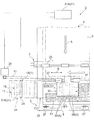
図示の液体噴射装置2は、記録装置の一例であるインクジェットプリンター2(液体噴射装置と同一の符号を使用する)である。このインクジェットプリンター2は、被液体噴射材(以下、「用紙」ともいう)Pの被液体噴射面9上に、第1の液C1である反応液を噴射して第1の液層51Aとなるプレコート層11を形成し、該プレコート層11上に第2の液C2である被反応液を噴射することで前記プレコート層11上で前記第1の液C1と第2の液C2を反応させて凝集物を得て画像13を形成することができるインクジェットプリンターである。
The illustrated
具体的には、用紙Pを搬送方向A(図2)に向けて搬送する搬送手段3と、第1の液C1を吐出する第1のノズル列5Aと、第2の液C2を吐出する第2のノズル列5Bとが前記搬送方向Aと交差する走査方向Bに並設された状態で同一のノズル形成面8に設けられている液体噴射ヘッド15と、前記液体噴射ヘッド15を搭載して前記走査方向Bに往復移動するキャリッジ17と、前記第1のノズル列5Aと第2のノズル列5Bを構成している各ノズル7の払拭処理時に使用される払拭装置1と、を備えることによって図示のインクジェットプリンター2は基本的に構成されている。
Specifically, the transport means 3 that transports the paper P in the transport direction A (FIG. 2), the
図2に示すように、搬送手段3は液体噴射実行領域23及び液体噴射ヘッドの回復処理領域(以下「払拭処理領域」とも言う)24の上流位置に設けられる一対のニップローラーによって構成されている搬送用ローラー25と、前記液体噴射実行領域23及び払拭処理領域24の下流位置に設けられる同じく一対のニップローラーによって構成されている排出用ローラー27と、を備えることによって一例として構成されている。
尚、前記払拭処理領域24は、後述する払拭装置1によって実行される液体吐出ノズル7の払拭処理時に使用される領域で、前記液体噴射実行領域23の側方に位置するキャリッジ17のホームポジションないしリターンポジションの領域に設けられている。
As shown in FIG. 2, the
The
前記液体噴射ヘッド15には、プレコート層11を形成するための第1の液C1を噴射する第1のノズル列5Aと、画像13を形成するための第2の液C2を噴射する第2のノズル列5Bとが走査方向Bに並ぶように同一のノズル形成面8上に並設されている。
一例として、図1、図2に示すように、図示の液体噴射ヘッド15にあっては、中間部6を挟んで向って左側に第1のノズル列5A、そして向って右側に第2のノズル列5Bがそれぞれ配設されている。
The
As an example, as shown in FIGS. 1 and 2, in the illustrated
また、前記第1のノズル列5Aと第2のノズル列5Bの境界の幅を持った領域を本明細書において中間部6と定義しており、該中間部6を始点として後述するように第1のノズル列5A側の払拭と、第2のノズル列5B側の払拭とが、工程を分けて実施されるように構成されている。
In addition, an area having a boundary width between the
キャリッジ17は、走査方向Bに延びるキャリッジガイド軸37に沿って走査方向Bに往復移動する前記液体噴射ヘッド15の往復搬送手段である。
そして、該キャリッジ17を往復移動させるための動力は、正逆転可能で単位ステップ毎の精密な送り制御が可能なモーター39から受けており、該モーター39の回転が歯付きベルト41を介して前記キャリッジ17に伝達されるようになっている。
The
The power for reciprocating the
また、このようにして構成される液体噴射装置2に対して適用される本発明における払拭装置1は、払拭動作時に前記ノズル形成面8に当接する上昇位置Hに移動し、払拭非動作時に前記ノズル形成面8から離間する下降位置Lに移動して退避する昇降可能なワイパー29と、前記ワイパー29と前記液体噴射ヘッド15の走査方向Bの相対位置を制御し、前記ノズル形成面8に備えられている第1のノズル列5Aと第2のノズル列5Bとの中間部6の存する位置を払拭開始位置Sとして、最初に前記ワイパー29を該払拭開始位置Sに当接させてからワイパー29の走査方向Bの左方ないし右方に相対移動させる制御部21と、を備えることによって基本的に構成されている。
Further, the
[実施例1](図1〜図6参照)
また、実施例1に係る払拭装置1Aにあっては、前記ワイパー29と前記液体噴射ヘッド15の走査方向Bの相対移動が前記ワイパー29の払拭開始位置Sを通る前記液体噴射ヘッド15の走査方向Bへの移動によって行われている。
前記ワイパー29は、直接液体噴射ヘッド15のノズル形成面8に当接して該ノズル形成面8に付着している第1の液C1と第2の液C2を拭き取る払拭動作を実行する部材である。そして、該ワイパー29は、その先端部31が静止状態の前記ノズル形成面8に当接したときに、走査方向Bの前記左右の両方向に一様な接触状態となる撓み変形をするように構成されている。その具体的な一例として、ワイパー29は撓み変形が可能な合成樹脂材料等によって形成されており、その先端部31の、上面が平らで走査方向Bの左右に幅が広い正面視略T字形状の先端部31Aによって一例として構成されている。
因みに、前記先端部31Aの正面視略T字形状は、ワイパー29が上昇して前記ノズル形成面8に当接した時、走査方向Bの前記左右の両方向に一様な接触状態となる撓み変形を実現する。
[Example 1] (See FIGS. 1 to 6)
In the
The
Incidentally, the front-view substantially T-shape of the
また、前記ワイパー29の先端部31は、形状の違う種々のタイプが採用でき、前述した正面視略T字形状の図3(A)に示す先端部31Aの他、図3(B)に示すようにワイパー29の他の部位の厚みと同じ厚さの板状の先端部31Bであってもよいし、図3(C)に示すように払拭動作時に拭き取った第1の液C1ないし第2の液C2の一部を受ける凹部33が形成された先端部31Cとすることも可能である。
また、前記図3(C)に示す凹部33の底部にワイパー29の一例として走査方向B側の一方の面につながる排液(インク)用の連通路35を更に設けた図3(D)に示すような構造の先端部31Dを採用することも可能である。
The
3D further includes a drainage (ink)
本実施例の制御部21Aは、ワイパー29の上下方向への移動の制御と、液体噴射ヘッド15の走査方向Bへの移動の制御を行っている。
具体的には、図5に示す模式図及び図6に示すフローチャートに示す動作の流れで本実施例に係る払拭装置1Aによるノズル7の回復処理(払拭処理)が実行されている。尚、具体的な制御の流れについては、次に述べる本発明に係る液体噴射ヘッドのノズル形成面の払拭方法の説明の中で併せて説明する。
The
Specifically, the recovery process (wiping process) of the
そして、このような構成の本実施例に係る払拭装置1Aを使用することによって実行される本発明に係るノズル形成面の払拭方法は、(1)第1移動工程と、(2)第1ワイパー当接工程と、(3)第1払拭工程と、(4)第1ワイパー退避工程と、(5)第2移動工程と、(6)第2ワイパー当接工程と、(7)第2払拭工程と、(8)第2ワイパー退避工程と、を備えることによって基本的に構成されている。 And the wiping method of the nozzle formation surface which concerns on this invention performed by using 1 A of wiping apparatuses which concern on a present Example of such a structure is (1) 1st movement process, (2) 1st wiper A contact process; (3) a first wiping process; (4) a first wiper retracting process; (5) a second moving process; (6) a second wiper contacting process; and (7) a second wiping process. The method basically includes a step and (8) a second wiper retracting step.
(1)第1移動工程(図5(A)(B)、図6参照)
第1移動工程は、液体噴射ヘッド15のノズル形成面8に備えられている第1のノズル列5Aと第2のノズル列5Bの中間部6が存する位置がワイパー29の払拭開始位置Sに来るように液体噴射ヘッド15を走査方向Bに移動させる工程である。
即ち、払拭装置1によるノズル7の払拭処理の実行が指令されると、制御部21から液体噴射ヘッド15を移動させるモーター39に信号が送られて図6中のステップS1で液体噴射実行領域23に存していた液体噴射ヘッド15が払拭開始位置Sに向けて左方に移動する(図5(A)(B)参照)。
(1) 1st movement process (refer to Drawing 5 (A) (B) and Drawing 6)
In the first movement step, the position where the
That is, when execution of the wiping process of the
(2)第1ワイパー当接工程(図5(C)、図6参照)
第1ワイパー当接工程は、前記払拭開始位置Sに来た液体噴射ヘッド15のノズル形成面8に向けて、下降位置Lで退避していたワイパー29を上昇させてワイパー29の先端部31を前記ノズル形成面8の中間部6の存する前記払拭開始位置Sに当接させる工程である、
即ち、液体噴射ヘッド15が前記払拭開始位置Sに至ると、図6中のステップS2に移行してワイパー29を上昇位置Hに移動させる(図5(C)参照)。
(2) 1st wiper contact process (refer to Drawing 5 (C) and Drawing 6)
In the first wiper contact step, the
That is, when the
(3)第1払拭工程(図5(D)(E)、図6参照)
第1払拭工程は、前記液体噴射ヘッド15を、走査方向Bの左方ないし右方に移動させて第2のノズル列5Bの存する側のノズル形成面8を拭き取る工程である。
即ち、ワイパー29が上昇位置Hに達すると、図6中のステップS3に移行して、液体噴射ヘッド15を第2のノズル列5Bを拭き取る方向(本実施例の場合には左方)に移動させる(図5(D)参照)。次に、図6中のステップS4で第2のノズル列5Bの拭き取りが終了したかどうかの判断が行われて終了していない場合には、前記ステップS3に戻って液体噴射ヘッド15の移動が継続される。
一方、第2のノズル列5Bの拭き取りが終了している場合には、ステップS5に移行して液体噴射ヘッド15を回復処理領域24の左端位置で停止させる(図5(E)参照)。
(3) 1st wiping process (refer to Drawing 5 (D) (E) and Drawing 6)
The first wiping step is a step of wiping the
That is, when the
On the other hand, when the wiping of the
(4)第1ワイパー退避工程(図5(F)、図6参照)
第1ワイパー退避工程は、前記第2のノズル列5Bの拭き取りに伴って上昇位置Hに移動していたワイパー29を下降させて下降位置Lに退避させる工程である。
即ち、液体噴射ヘッド15が回復処理領域24の左端位置で停止したら、図6中のステップS6に移行してワイパー29を下降させて下降位置Lに退避させる(図5(F)参照)。
(4) First wiper retracting step (see FIGS. 5F and 6)
The first wiper retracting step is a step of lowering the
That is, when the
(5)第2移動工程(図5(G)、図6参照)
第2移動工程は、前記中間部6が存する位置がワイパー29の払拭開始位置Sに来るように液体噴射ヘッド15を移動させる工程である。
即ち、前記ワイパー29が下降位置Lに至ると、図6中のステップS7に移行して液体噴射ヘッド15を回復処理領域24の左端位置から払拭開始位置Sに向けて右方に移動させる(図5(G)参照)。
(5) Second moving step (see FIGS. 5G and 6)
The second moving step is a step of moving the
That is, when the
(6)第2ワイパー当接工程(図5(H)、図6参照)
第2ワイパー当接工程は、前記払拭開始位置Sに来た液体噴射ヘッド15のノズル形成面8に向けて、下降位置Lで退避していたワイパー29を上昇させてワイパー29の先端部31を前記ノズル形成面8の中間部6の存する位置に当接させる工程である。
即ち、液体噴射ヘッド15が前記払拭開始位置Sに至ると、図6中のステップ8に移行してワイパー29を上昇位置Hに移動させる(図5(H)参照)。
(6) Second wiper contact process (see FIGS. 5H and 6)
In the second wiper contact step, the
That is, when the
(7)第2払拭工程(図5(I)(J)、図6参照)
第2払拭工程は、前記液体噴射ヘッド15を、走査方向Bの右方ないし左方に移動させて第1のノズル列5Aの存する側のノズル形成面8を拭き取る工程である。
即ち、ワイパー29が上昇位置Hに達すると、図6中のステップS9に移行して液体噴射ヘッド15を第1のノズル列5Aを拭き取る方向(本実施例の場合には右方)に移動させる(図5(I)参照)。次に、図6中のステップ10で第1のノズル列5Aの拭き取りが終了したかどうかの判断が行われて終了していない場合には、前記ステップS9に戻って液体噴射ヘッド15の移動が継続される。
一方、第1のノズル列5Aの拭き取りが終了している場合には、ステップS11に移行して液体噴射ヘッド15を回復処理領域24の右端位置で停止させる(図5(J)参照)。
(7) 2nd wiping process (refer FIG. 5 (I) (J) and FIG. 6)
The second wiping step is a step of wiping the
That is, when the
On the other hand, when the wiping of the
(8)第2ワイパー退避工程(図5(K)、図6参照)
第2ワイパー退避工程は、前記第1のノズル列5Aの拭き取りに伴って上昇位置に移動していたワイパー29を下降させて下降位置で退避させる工程である。
即ち、液体噴射ヘッド15が回復処理領域24の右端位置で停止したら、図6中のステップS12に移行してワイパー29を下降させて下降位置Lに退避させてノズル7の次の払拭処理に備える。また、液体噴射ヘッド15は、回復処理領域24から液体噴射実行領域23に移動して、液体噴射実行動作を再開する(図5(K)参照)。
(8) Second wiper retracting step (see FIGS. 5K and 6)
The second wiper retracting step is a step of lowering and retracting the
That is, when the
この他、前記(3)の第1払拭工程の後と、前記(7)の第2払拭工程の後に払拭動作後のワイパー29を洗浄して次の使用に備える洗浄工程を設けることも可能である。
この場合、前記洗浄工程では、図4(A)(B)に示すような洗浄機構53が一例として適用できる。このうち図4(A)に示す洗浄機構53Aは、ワイパー29の下降位置Lにワイパー29の先端部31における先端面31aに作用する舌片部57と、前記先端部31の側周面31bに作用する筒状部59と、を一体に備える吸液性を有する拭き取り部材55を配置し、更に、前記拭き取り部材55の周囲に洗浄液61が入った液槽63を配設することによって構成されている。
In addition, after the first wiping step (3) and after the second wiping step (7), it is possible to provide a cleaning step for cleaning the
In this case, a
即ち、当該図4(A)に示す洗浄機構53Aの場合には、ワイパー29が上昇ないし下降する際にワイパー29の先端部31における先端面31aと側周面31bが前記拭き取り部材55の舌片部57と筒上部59に摺接することによって、ワイパー29の先端部31に付着している第1の液C1ないし第2の液C2の拭き取りが実行される。
また、前記拭き取り部材55の下部は図示のように洗浄液61に浸っているため、該洗浄液61が吸い上げられて拭き取り部材55の全体に行き渡っているから洗浄液61による洗浄作用も期待できる。
That is, in the case of the
Further, since the lower part of the wiping
一方、図4(B)に示す洗浄機構53Bは、液体噴射ヘッド15の走査経路上に同じく走査方向Bに往復移動可能な洗浄ヘッド65を設け、該洗浄ヘッド65に対して洗浄液61を吐出する洗浄液ノズル67と、エア69を噴射するエアノズル71とを配設した構造をとっている。
即ち、当該図4(B)に示す洗浄機構53Bの場合には、ワイパー29の存する払拭開始位置Sに液体噴射ヘッド15が位置していないタイミングで前記洗浄ヘッド65を前記払拭開始位置Sに移動させる。そして、前記洗浄液ノズル67から吐出される洗浄液61によってワイパー29を洗浄し、前記エアノズル71から噴射されるエア69によって洗浄したワイパー29の表面を乾かしたり、ワイパー29に付着している異物を吹き落とすようになっている。
On the other hand, the
That is, in the case of the
そして、このようにして構成される実施例1に係る払拭装置1A及び該払拭装置1Aを使用することによって実行される本発明に係るノズル形成面の払拭方法によれば、前記第1の液C1と第2の液C2が同一のノズル形成面8上で混ざることによって生成される凝集物の発生を効果的に防止してノズルの動作回復を図ることができる。従って、液体噴射ヘッド15の性能を良好に保って液体噴射実行品質を高めることが可能になる。
And according to the
[実施例2](図7、図8参照)
実施例2に係る払拭装置1Bは、前記実施例1に係る払拭装置1Aと同様の構造を有しており、前記ワイパー29と前記液体噴射ヘッド15の走査方向Bの相対移動が前記ワイパー29に払拭開始位置Sを通る前記液体噴射ヘッド15の走査方向Bへの移動によって行われている点でも前記実施例と同様の構成を有している。
[Example 2] (See FIGS. 7 and 8)
The
但し、ワイパー29が図3(B)の構造のものであること、及びワイパー29と液体噴射ヘッド15の制御の仕方が幾分、前記実施例1のものと異なっている。即ち、本実施例では前記ワイパー29の下降位置Lから上昇位置Hへの移動に合わせて前記ワイパー29と前記液体噴射ヘッド15の前記ワイパー29の払拭開始位置Sへの相対移動を実行し、前記ワイパー29に前記ノズル形成面8が当接した時の前記液体噴射ヘッド15の移動方向によって、前記ノズル形成面8に当接した時のワイパー29における先端部31の撓み姿勢、即ち先端部31が曲がる方向を制御している。
However, the
具体的には、図8中のステップS1で液体噴射ヘッド15を払拭開始位置Sへ向けて左方に移動させると同時にワイパー29を上昇位置Hに移動させる(図7(A)(B)、図8参照)。この場合、ワイパー29の先端部31がノズル形成面8に当接したときに、前記液体噴射ヘッド15の左方への移動によってワイパー29の先端部31には図示のように該先端部31が左方に曲がる撓み姿勢が付与される(図7(B)参照)。
次に、図6中のステップS3〜S6と同様の図8中のステップS2〜S5が実行されて(図7(C)(D)(E)参照)、図8中のステップS6に移行する。
Specifically, in step S1 in FIG. 8, the
Next, steps S2 to S5 in FIG. 8 similar to steps S3 to S6 in FIG. 6 are executed (see FIGS. 7C, 7D, and 7E), and the process proceeds to step S6 in FIG. .
図8中のステップS6では、液体噴射ヘッド15を払拭開始位置Sに向けて右方に移動させると同時にワイパー29を上昇位置Hに移動させる(図7(F)参照)。この場合、ワイパー29の先端部31がノズル形成面8に当接したときに、前記液体噴射ヘッド15の右方への移動によってワイパー29の先端部31には図示のように該先端部31が右方に曲がる前記図7(B)と逆の撓み姿勢が付与される(図7(F)参照)。
次に、図6中のステップS9〜S12と同様の図8中のステップS7〜S10が実行されて(図7(G)(H)(I))、一連のノズル7の払拭処理は終了する。
In step S6 in FIG. 8, the
Next, steps S7 to S10 in FIG. 8 similar to steps S9 to S12 in FIG. 6 are executed (FIGS. 7G, 7H, and 7I), and a series of wiping processes for the
そして、このような制御を行う実施例2に係る払拭装置1Bによっても、前記実施例1と同様の作用、効果が発揮され、更に本実施例の特有の作用、効果としてワイパー29の上昇と液体噴射ヘッド15の走査方向Bへの移動をタイミングを合わせて同時に実行することによって工程の短縮と、ワイパー29の先端部31の形状に因らないワイパー29の先端部31における撓み姿勢の制御(曲がり方向の制御)とが可能になる。
The
[実施例3](図9、図10参照)
実施例3に係る払拭装置1Cは、前記実施例1に係る払拭装置1Aと同様の構造を有している。但し、前記ワイパー29と前記液体噴射ヘッド15の走査方向Bの相対移動が前記ワイパー29の払拭開始位置Sを通る前記ワイパー29の走査方向Bへの移動によって行われている点で前記実施例1と相違している。
[Example 3] (See FIGS. 9 and 10)
The
即ち、本実施例では、前記実施例1が前記液体噴射ヘッド15を走査方向Bに移動させることでノズル列5A、5Bの個別の払拭動作を行っていたのに代えて前記ワイパー29を走査方向Bに移動させることで同様のノズル列5A、5Bの個別の払拭動作を行っている。
That is, in this embodiment, the
具体的には、図10中のステップS1で液体噴射ヘッド15を払拭開始位置Sへ向けて左方に移動させると同時にワイパー29を払拭開始位置Sに移動させる(図9(A)(B)参照)。
次に、図10中のステップS2に移行してワイパー29を上昇位置Hに移動させてワイパー29をノズル形成面8の払拭開始位置Sに接触させる(図9(C)参照)。
Specifically, in step S1 in FIG. 10, the
Next, the process proceeds to step S2 in FIG. 10, and the
次に、図10中のステップS3に移行してワイパー29を第2のノズル列5Bを拭き取る方向である右方に移動させる(図9(D)参照)。
Next, the process proceeds to step S3 in FIG. 10, and the
次に、図10中のステップS4に移行して第2のノズル列5Bの拭き取りが終了したかどうかの判断が行われ、終了していない場合には、図10中のステップS4に戻り、終了している場合には、図10中のステップS5に移行してワイパー29を回復処理領域24の右端位置で停止させる(図9(E)参照)。
次に、図10中のステップS6に移行して、ワイパー29を下降位置Lに退避させて(図9(F)参照)、更に、図10中のステップS7に移行して、ワイパー29を回復処理領域24の右端位置から払拭開始位置Sのある左方に移動させる(図9(G)参照)。
Next, the process proceeds to step S4 in FIG. 10 to determine whether or not the wiping of the
Next, the process proceeds to step S6 in FIG. 10, the
次に、図10中のステップS8に移行してワイパー29を上昇位置Hに移動させて払拭開始位置Sに接触させる(図9(H)参照)。更に、図10中のステップS9に移行して、ワイパー29を第1のノズル列5Aを拭き取る方向である左方に移動させる(図9(I)参照)。
次に、図10中のステップS10に移行して第1のノズル列5Aの拭き取りが終了したかどうかの判断が行われ、終了していないと判断された場合には図10中のステップS9に戻り、終了していると判断された場合には図10中のステップS11に移行してワイパー29を回収処理領域24の左端位置で停止させる(図9(J)参照)。
更に、図10のステップS12に移行し、ワイパー29を下降位置Lに退避させる(図9(K)参照)。
Next, the process proceeds to step S8 in FIG. 10, and the
Next, the process proceeds to step S10 in FIG. 10 to determine whether or not the wiping of the
Further, the process proceeds to step S12 in FIG. 10, and the
そして、このような制御を行う実施例3に係る払拭装置1Cによっても、前記実施例1と同様の作用、効果が発揮され、更に本実施例の特有の作用、効果として既存の液体噴射ヘッド15の移動態様を変更することなく、払拭動作を実行することが可能になる。
The
[実施例4](図11、図12参照)
実施例4に係る払拭装置1Dは、前記実施例1に係る払拭装置1Aと同様の構造を有している。但し、ワイパー29が図3(B)の構造のものであること、及び前記ワイパー29と前記液体噴射ヘッド15の走査方向Bの相対移動が前記実施例3に係る払拭装置1Cと同様、前記ワイパー29の走査方向Bへの移動によって行われている点で前記実施例1と相違している。
[Example 4] (See FIGS. 11 and 12)
The
また、ワイパー29と液体噴射ヘッド15の制御の仕方が幾分、前記実施例3のものと異なっており、前記実施例2に係る払拭装置1Bと同様、ワイパー29の上昇位置Hへの移動に合わせてワイパー29と液体噴射ヘッド15の払拭開始位置Sへの相対移動を実行し、ワイパー29がノズル形成面8に当接した時のワイパー29の移動方向によって、ノズル形成面8に当接した時のワイパー29の先端部31における撓み姿勢(曲がり方向)を制御している。
Further, the control method of the
具体的には、図12中のステップS1で液体噴射ヘッド15を払拭開始位置Sのある左方に移動させると同時にワイパー29を払拭開始位置Sのある右方に移動させながら上昇位置Hに移動させる(図11(A)(B)参照)。この場合、ワイパー29の先端部31がノズル形成面8に当接したときに、前記ワイパー29の右方への移動及び液体噴射ヘッド15の左方向への移動のいずれか一方又は双方によって該ワイパー29の先端部31には図示のように該先端部31が左方に曲がる撓み姿勢が付与される(図11(B)参照)。
次に、図10中のステップS3〜S6と同様の図12中のステップS2〜S5が実行されて(図11(C)(D)(E)参照)、図12中のステップS6に移行する。
Specifically, in step S1 in FIG. 12, the
Next, steps S2 to S5 in FIG. 12 similar to steps S3 to S6 in FIG. 10 are executed (see FIGS. 11C, 11D, and 11E), and the process proceeds to step S6 in FIG. .
図12中のステップS6では、ワイパー29を回復処理領域24の右端位置から払拭開始位置Sのある左方に移動させながら上昇位置Hに移動させる(図11(F)参照)。この場合、ワイパー29の先端部31がノズル形成面8に当接したときに、前記ワイパー29の左方への移動によって該ワイパー29の先端部31には図示のように該先端部31が右方に曲がる前記図11(B)と逆の撓み姿勢が付与される(図11(F)参照)。
次に、図10中のステップS9〜S12と同様の図12中のステップS7〜S10が実行されて(図11(G)(H)(I))、一連のノズル7の払拭処理は終了する。
In step S6 in FIG. 12, the
Next, steps S7 to S10 in FIG. 12 similar to steps S9 to S12 in FIG. 10 are executed (FIGS. 11G, 11H, and 11), and the series of
そして、このような制御を行う実施例4に係る払拭装置1Dによっても、前記実施例1と同様の作用、効果が発揮され、更に本実施例の特有の作用、効果としてワイパー29の上昇及び走査方向Bへの移動をタイミングを合わせて同時に実行することによって工程の短縮と、ワイパー29の先端部31の形状に因らないワイパー29の先端部31における撓み姿勢(曲がり方向)の制御とが可能になる。
The wiping
[実施例5](図13、図14参照)
実施例5に係る払拭装置1Eは、前記実施例1に係る払拭装置1Aと同様の構造を有している。但し、前記ワイパー29と前記液体噴射ヘッド15の走査方向Bの相対移動がこれら双方の移動によって行われている点で前記実施例1と相違している。
[Example 5] (See FIGS. 13 and 14)
The
これに伴って、ワイパー29と液体噴射ヘッド15の制御の仕方が幾分、前記実施例4のものと異なっている。
Accordingly, the control method of the
具体的には、図14中のステップS1で液体噴射ヘッド15を払拭開始位置Sのある左方に移動させると同時にワイパー29を上昇位置Hに移動させる(図13(A)(B)参照)。この場合も前記実施例2と同様、ワイパー29の先端部31には図示のように該先端部31が左方に曲がる撓み姿勢が付与される(図13(B)参照)。
次に、図12中のステップS2〜S6と同様の図14中のステップS2〜S6が実行されて(図13(C)(D)(E)(F)参照)、図14中のステップS7に移行する。
Specifically, in step S1 in FIG. 14, the
Next, steps S2 to S6 in FIG. 14 similar to steps S2 to S6 in FIG. 12 are executed (see FIGS. 13C, 13D, 13E, and 13F), and step S7 in FIG. Migrate to
また、図14中のステップS7では、液体噴射ヘッド15を第1のノズル列5Aを拭き取る方向である右方に移動させる(図13(G)参照)。次に、図14中のステップS8に移行して第1のノズル列5Aの拭き取りが終了したかどうかの判断が行われて、終了していない場合には、図14中のステップS7に戻り、終了している場合には図14中のステップS9に移行して液体噴射ヘッド15を回復処理領域24の右端位置で停止させる(図13(H)参照)。
更に、図14中のステップS10に移行して、ワイパー29を下降させて下降位置Lに退避させ、次のノズル7の払拭処理を待つ。
Further, in step S7 in FIG. 14, the
Further, the process proceeds to step S10 in FIG. 14, the
そして、このような制御を行う実施例5に係る払拭装置1Eによっても、前記実施例1と同様の作用、効果が発揮され、更に本実施例の場合には、前記第4の実施例のワイパー29における走査方向Bの移動ストロークが短くなるから、ノズル7の払拭処理がより円滑になって、効率の良いノズル7の払拭処理が実行できるようになる。
The
[他の実施例]
本発明に係る払拭装置1、該払拭装置1を適用した液体噴射装置2及び前記払拭装置1を使用することによって実行されるノズル回復方法は、以上述べたような構成を有することを基本とするものであるが、本願発明の要旨を逸脱しない範囲内の部分的構成の変更や省略等を行うことも勿論可能である。
[Other embodiments]
The
例えば、前記ワイパー29は、1種類のみ設ける他、前記第1のノズル列5Aが備えられているノズル形成面8を拭き取る第1のワイパーと、前記第2のノズル列5Bが備えられているノズル形成面8を拭き取る第2のワイパーとが、互いに前記相対移動の方向に離間して別に設けられる構成であってもよい。
この構成にすると、第1のノズル列5A部分には第1のワイパーだけが接触し、第2のノズル列5B部分には第2のワイパーだけが接触するので、払拭の際に第1の液と第2の液がノズル形成面で混ざる虞が無いという効果が得られる。
For example, in addition to providing only one type of
With this configuration, only the first wiper is in contact with the
また、前記実施例1の説明の中で述べた図3に示すワイパー29の種々の先端部31を実施例2〜実施例5に適用することも可能であり、同じく前記実施例1の説明の中で述べた図4に示す洗浄機構53を実施例2〜実施例5に適用することも可能である。
また、前記ワイパー29の先端部31は、図3に示すものに限らず、同様の作用、効果を奏する他の形状ないし構造の先端部31であってもよい。同様に洗浄機構53としても図4に示すものに限らず、同様の作用、効果を奏する他の機構を採用することが可能である。
Also,
Further, the
この他、本発明の払拭装置1が適用される液体噴射装置2は、前述したようなインクジェットプリンター2に限らず、反応する2液を吐出するノズル列5が走査方向Bに並設されている種々のタイプの液体噴射装置2に適用可能である。
In addition, the
1 払拭装置、2 インクジェットプリンター(液体噴射装置)、3 搬送手段、
5 ノズル列、6 中間部、7 ノズル、8 ノズル形成面、9 被液体噴射面、
11 プレコート層、13 画像、15 液体噴射ヘッド、17 キャリッジ、
21 制御部、23 液体噴射実行領域、24 回復処理領域(払拭処理領域)、
25 搬送用ローラー、27 排出用ローラー、29 ワイパー、31 先端部、
31a 先端面、31b 側周面、33 凹部、35 連通路、
37 キャリッジガイド軸、39 モーター、41 歯付きベルト、
51 液(インク)層、53 洗浄機構、55 拭き取り部材、57 舌片部、
59 筒状部、61 洗浄液、63 液槽、65 洗浄ヘッド、67 洗浄液ノズル、
69 エア、71 エアノズル、 P 用紙(被液体噴射材)、A 搬送方向、
B 走査方向、C 液(インク)、H 上昇位置、L 下降位置、
S 払拭開始位置
1 wiping device, 2 ink jet printer (liquid ejecting device), 3 transport means,
5 nozzle row, 6 middle part, 7 nozzle, 8 nozzle forming surface, 9 liquid ejection surface,
11 Precoat layer, 13 images, 15 Liquid jet head, 17 Carriage,
21 control unit, 23 liquid ejection execution area, 24 recovery process area (wiping process area),
25 Transport roller, 27 Discharge roller, 29 Wiper, 31 Tip,
31a tip surface, 31b side peripheral surface, 33 recess, 35 communication path,
37 Carriage guide shaft, 39 Motor, 41 Toothed belt,
51 liquid (ink) layer, 53 cleaning mechanism, 55 wiping member, 57 tongue piece,
59 cylindrical part, 61 cleaning liquid, 63 liquid tank, 65 cleaning head, 67 cleaning liquid nozzle,
69 air, 71 air nozzle, P paper (liquid jetting material), A transport direction,
B scanning direction, C liquid (ink), H ascending position, L descending position,
S Wiping start position
Claims (6)
前記ノズル形成面に対して接触可能に設けられ、前記ノズル形成面を払拭するワイパーと、
前記液体噴射ヘッドが被液体噴射材に前記液を噴射する液体噴射実行領域の側方に位置する回復処理領域において、前記ワイパーの接触動作と、該ワイパーと前記液体噴射ヘッドの前記ノズル列と交差する方向における相対移動動作とを組み合せて実行される払拭動作を制御する制御部と、を備える液体噴射装置であって、
前記制御部は、前記ワイパーが前記第1のノズル列と第2のノズル列との間の位置を払拭開始位置として該払拭開始位置に前記ワイパーを接触させ、前記相対移動の一方向への移動によって該ワイパーが前記ノズル形成面の該払拭開始位置より前記液体噴射実行領域に近い領域に移動する一方向の払拭を実行し、次いで前記ワイパーを前記払拭開始位置に再度接触させ、前記相対移動の他方向への移動によって該ワイパーが前記ノズル形成面の該払拭開始位置より前記液体噴射実行領域から離れた領域に移動する他方向の払拭を実行するように構成されていることを特徴とする液体噴射装置。 A liquid ejecting head in which a first nozzle row for discharging a first liquid and a second nozzle row for discharging a second liquid are arranged in parallel on a nozzle forming surface;
A wiper provided so as to be able to contact the nozzle forming surface and wiping the nozzle forming surface;
In the recovery processing region located on the side of the liquid ejection execution region in which the liquid ejecting head ejects the liquid onto the liquid ejecting material, the wiper contact operation and the wiper intersect the nozzle row of the liquid ejecting head. A control unit that controls a wiping operation that is executed in combination with a relative movement operation in a direction to perform,
The control unit causes the wiper to contact the wiper at a wiping start position with a position between the first nozzle row and the second nozzle row as a wiping start position, and moves in one direction of the relative movement. The wiper performs unidirectional wiping in which the wiper moves from the wiping start position on the nozzle forming surface to a region closer to the liquid ejection execution region, and then the wiper is brought into contact with the wiping start position again to perform the relative movement. A liquid configured to execute wiping in the other direction in which the wiper moves to a region away from the liquid jetting execution region from the wiping start position on the nozzle forming surface by moving in the other direction. Injection device.
前記制御部は、前記ワイパーの非接触位置から接触位置への移動に合わせて、前記ワイパーと前記液体噴射ヘッドの前記ワイパーの払拭開始位置への相対移動を実行し、前記ワイパーが前記ノズル形成面に当接した時の前記相対移動の移動方向によって前記ノズル形成面に当接した時のワイパー先端部の撓み姿勢を制御するように構成されていることを特徴とする液体噴射装置。 The liquid ejecting apparatus according to claim 1,
The control unit performs relative movement of the wiper and the liquid ejecting head to the wiping start position of the wiper in accordance with the movement of the wiper from the non-contact position to the contact position, and the wiper moves the nozzle forming surface. A liquid ejecting apparatus configured to control a bending posture of a wiper tip when abutting against the nozzle forming surface according to a moving direction of the relative movement when abutting against a nozzle.
前記相対移動方向において、前記ワイパーの先端部の前記ノズル形成面に当接する上面の幅は、該先端部以外の部分より前記相対移動方向の両方向に広く、前記第1のノズル列と第2のノズル列との間の距離より狭いことを特徴とする液体噴射装置。 The liquid ejecting apparatus according to claim 1 or 2,
In the relative movement direction, the width of the top surface of contact with the nozzle forming surface of the distal end portion of the wiper is wider in both directions of the relative movement direction than the portion other than the tip portion, the first nozzle row and the second A liquid ejecting apparatus characterized in that it is narrower than the distance between the nozzle row .
前記相対移動方向において、前記ワイパーの先端部の幅は、前記第1のノズル列と第2のノズル列との間の距離より狭く、該先端部の前記ノズル形成面と対向する部位に凹部が形成されていることを特徴とする液体噴射装置。 In the liquid ejecting apparatus according to any one of claims 1 to 3,
In the relative movement direction, the width of the tip of the wiper is narrower than the distance between the first nozzle row and the second nozzle row, and a recess is formed at a portion of the tip facing the nozzle formation surface. A liquid ejecting apparatus which is formed.
前記払拭動作後のワイパーの退避位置に前記払拭動作後のワイパーに摺接する拭き取り部材と、前記拭き取り部材に洗浄液を供給可能な液槽と、を有し、該ワイパーを洗浄する洗浄機構が設けられていることを特徴とする液体噴射装置。 In the liquid ejecting apparatus according to any one of claims 1 to 4,
A wiping member that slides on the wiper after the wiping operation and a liquid tank capable of supplying a cleaning liquid to the wiping member are provided at a retracted position of the wiper after the wiping operation , and a cleaning mechanism for cleaning the wiper is provided. A liquid ejecting apparatus.
前記ノズル形成面の前記払拭開始位置に向けて前記ワイパーの先端部を前記払拭開始位置に当接させる第1ワイパー当接工程と、
前記液体噴射ヘッドを相対移動方向における一方向に移動させて第1のノズル列の存する側のノズル形成面を接触している前記ワイパーで払拭する第1払拭工程と、
前記第1払拭工程後に前記ワイパーを退避させる第1ワイパー退避工程であって、該ワイパーを退避させる際に洗浄する洗浄工程を含む第1ワイパー退避工程と、
前記ノズル形成面の前記払拭開始位置に退避状態の前記ワイパーが位置するように該液体噴射ヘッドを相対移動させる第2移動工程と、
前記ノズル形成面の前記払拭開始位置に向けて前記ワイパーの先端部を前記払拭開始位置に当接させる第2ワイパー当接工程と、
前記液体噴射ヘッドを相対移動方向における他方向に移動させて第2のノズル列の存する側のノズル形成面を接触している前記ワイパーで払拭する第2払拭工程と、
前記第2払拭工程後に前記ワイパーを退避させる第2ワイパー退避工程であって、該ワイパーを退避させる際に洗浄する洗浄工程を含む第2ワイパー退避工程と、を備えていることを特徴とする液体噴射ヘッドのノズル形成面の払拭方法。 The liquid ejecting head is relatively moved such that the wiper in the retracted state is positioned at the wiping start position located between the first nozzle row and the second nozzle row provided on the nozzle forming surface of the liquid ejecting head. 1 moving process,
A first wiper contact step of bringing the tip of the wiper into contact with the wiping start position toward the wiping start position of the nozzle forming surface;
A first wiping step in which the liquid ejecting head is moved in one direction in the relative movement direction and wiped with the wiper contacting the nozzle forming surface on the side where the first nozzle row exists;
A first wiper retracting step of retracting the wiper after the first wiping step, the first wiper retracting step including a cleaning step of cleaning when the wiper is retracted ;
A second moving step of relatively moving the liquid jet head as the wiper of the saving state to the wiping start position of the nozzle formation surface is positioned,
A second wiper contact step of bringing the tip of the wiper into contact with the wiping start position toward the wiping start position of the nozzle forming surface;
A second wiping step of moving the liquid ejecting head in the other direction of the relative movement direction and wiping with the wiper contacting the nozzle forming surface on the side where the second nozzle row exists;
A liquid comprising: a second wiper retracting process for retracting the wiper after the second wiping process, and a second wiper retracting process including a cleaning process for cleaning when the wiper is retracted. A method of wiping the nozzle forming surface of the ejection head.
Priority Applications (1)
| Application Number | Priority Date | Filing Date | Title |
|---|---|---|---|
| JP2010258159A JP5668918B2 (en) | 2010-11-18 | 2010-11-18 | Liquid ejecting apparatus and method for wiping nozzle forming surface of liquid ejecting head |
Applications Claiming Priority (1)
| Application Number | Priority Date | Filing Date | Title |
|---|---|---|---|
| JP2010258159A JP5668918B2 (en) | 2010-11-18 | 2010-11-18 | Liquid ejecting apparatus and method for wiping nozzle forming surface of liquid ejecting head |
Publications (3)
| Publication Number | Publication Date |
|---|---|
| JP2012106442A JP2012106442A (en) | 2012-06-07 |
| JP2012106442A5 JP2012106442A5 (en) | 2013-10-24 |
| JP5668918B2 true JP5668918B2 (en) | 2015-02-12 |
Family
ID=46492621
Family Applications (1)
| Application Number | Title | Priority Date | Filing Date |
|---|---|---|---|
| JP2010258159A Active JP5668918B2 (en) | 2010-11-18 | 2010-11-18 | Liquid ejecting apparatus and method for wiping nozzle forming surface of liquid ejecting head |
Country Status (1)
| Country | Link |
|---|---|
| JP (1) | JP5668918B2 (en) |
Families Citing this family (2)
| Publication number | Priority date | Publication date | Assignee | Title |
|---|---|---|---|---|
| JP6111479B2 (en) * | 2012-10-31 | 2017-04-12 | 株式会社ミマキエンジニアリング | Inkjet recording device |
| JP7275819B2 (en) | 2019-05-07 | 2023-05-18 | セイコーエプソン株式会社 | LIQUID EJECTING DEVICE, MAINTENANCE METHOD OF LIQUID EJECTING DEVICE |
Family Cites Families (9)
| Publication number | Priority date | Publication date | Assignee | Title |
|---|---|---|---|---|
| US5396277A (en) * | 1992-09-25 | 1995-03-07 | Hewlett-Packard Company | Synchronized carriage and wiper motion method and apparatus for ink-jet printers |
| JPH06270420A (en) * | 1993-03-19 | 1994-09-27 | Fuji Xerox Co Ltd | Maintenance device of ink jet recording apparatus |
| JPH07314700A (en) * | 1994-05-27 | 1995-12-05 | Canon Inc | Ink-jet recording device |
| JPH09150521A (en) * | 1995-11-29 | 1997-06-10 | Funai Electric Co Ltd | Wiper for cleaning print head |
| JP3137256B2 (en) * | 1995-11-29 | 2001-02-19 | 船井電機株式会社 | Print head maintenance mechanism |
| JP3768633B2 (en) * | 1997-02-14 | 2006-04-19 | キヤノン株式会社 | Inkjet cartridge and printing apparatus |
| JP4666946B2 (en) * | 2004-04-28 | 2011-04-06 | キヤノン株式会社 | Discharge port surface cleaning method, liquid discharge apparatus, and probe carrier manufacturing apparatus |
| EP2353869A1 (en) * | 2008-05-29 | 2011-08-10 | Eastman Kodak Company | Multicolor printhead maintenance station |
| JP2010046838A (en) * | 2008-08-20 | 2010-03-04 | Brother Ind Ltd | Image recording device |
-
2010
- 2010-11-18 JP JP2010258159A patent/JP5668918B2/en active Active
Also Published As
| Publication number | Publication date |
|---|---|
| JP2012106442A (en) | 2012-06-07 |
Similar Documents
| Publication | Publication Date | Title |
|---|---|---|
| JP4565637B2 (en) | Inkjet recording device | |
| JP6379480B2 (en) | Liquid ejector | |
| US20120299996A1 (en) | Ink jet printing apparatus | |
| US20190030899A1 (en) | Ink jet printer | |
| JP6157131B2 (en) | Recording apparatus and cleaning method thereof | |
| JP5927989B2 (en) | Image forming apparatus | |
| JP5668918B2 (en) | Liquid ejecting apparatus and method for wiping nozzle forming surface of liquid ejecting head | |
| US20050248613A1 (en) | Head maintenance device and ink jet printer incorporating the same | |
| US9457578B2 (en) | Inkjet recording apparatus | |
| JP5824956B2 (en) | Image forming apparatus | |
| JP5892099B2 (en) | Liquid ejection device | |
| JP6150537B2 (en) | Ink jet recording apparatus and recording head wiping method | |
| JP2007176008A (en) | Liquid injection apparatus and wiping method of liquid injection apparatus | |
| JP2010188583A5 (en) | ||
| JP6432264B2 (en) | Liquid ejection device | |
| US9022523B2 (en) | Inkjet recording apparatus having a first and second cover | |
| JP2014043026A (en) | Recording device | |
| JP2010208268A (en) | Inkjet recording device | |
| JP2013202892A (en) | Inkjet recording apparatus | |
| JP6451188B2 (en) | Liquid ejection device | |
| JP6602020B2 (en) | Liquid ejection device | |
| CN107972360B (en) | Printing apparatus and control method | |
| JP2006240168A (en) | Ink-jet recording device, device for recovering ink-jet recording device, and method of recovering ink-jet recording device | |
| JP6319146B2 (en) | Inkjet recording device | |
| JP6308154B2 (en) | Inkjet recording device |
Legal Events
| Date | Code | Title | Description |
|---|---|---|---|
| A521 | Written amendment |
Free format text: JAPANESE INTERMEDIATE CODE: A523 Effective date: 20130906 |
|
| A621 | Written request for application examination |
Free format text: JAPANESE INTERMEDIATE CODE: A621 Effective date: 20130906 |
|
| A977 | Report on retrieval |
Free format text: JAPANESE INTERMEDIATE CODE: A971007 Effective date: 20140207 |
|
| A131 | Notification of reasons for refusal |
Free format text: JAPANESE INTERMEDIATE CODE: A131 Effective date: 20140219 |
|
| A977 | Report on retrieval |
Free format text: JAPANESE INTERMEDIATE CODE: A971007 Effective date: 20140327 |
|
| A521 | Written amendment |
Free format text: JAPANESE INTERMEDIATE CODE: A523 Effective date: 20140418 |
|
| TRDD | Decision of grant or rejection written | ||
| A01 | Written decision to grant a patent or to grant a registration (utility model) |
Free format text: JAPANESE INTERMEDIATE CODE: A01 Effective date: 20141119 |
|
| A61 | First payment of annual fees (during grant procedure) |
Free format text: JAPANESE INTERMEDIATE CODE: A61 Effective date: 20141202 |
|
| R150 | Certificate of patent or registration of utility model |
Ref document number: 5668918 Country of ref document: JP Free format text: JAPANESE INTERMEDIATE CODE: R150 |
|
| S531 | Written request for registration of change of domicile |
Free format text: JAPANESE INTERMEDIATE CODE: R313531 |
|
| R350 | Written notification of registration of transfer |
Free format text: JAPANESE INTERMEDIATE CODE: R350 |