EP2352894B9 - Vent - Google Patents
Vent Download PDFInfo
- Publication number
- EP2352894B9 EP2352894B9 EP09740694.6A EP09740694A EP2352894B9 EP 2352894 B9 EP2352894 B9 EP 2352894B9 EP 09740694 A EP09740694 A EP 09740694A EP 2352894 B9 EP2352894 B9 EP 2352894B9
- Authority
- EP
- European Patent Office
- Prior art keywords
- vent
- rear face
- aperture
- valve
- plate
- Prior art date
- Legal status (The legal status is an assumption and is not a legal conclusion. Google has not performed a legal analysis and makes no representation as to the accuracy of the status listed.)
- Active
Links
- XLYOFNOQVPJJNP-UHFFFAOYSA-N water Substances O XLYOFNOQVPJJNP-UHFFFAOYSA-N 0.000 claims description 18
- 241000238631 Hexapoda Species 0.000 claims description 6
- 238000007789 sealing Methods 0.000 claims description 5
- 239000011449 brick Substances 0.000 description 8
- 239000000463 material Substances 0.000 description 7
- 239000012530 fluid Substances 0.000 description 6
- 239000003643 water by type Substances 0.000 description 5
- 239000000243 solution Substances 0.000 description 4
- 238000010276 construction Methods 0.000 description 3
- 239000004743 Polypropylene Substances 0.000 description 2
- 239000000853 adhesive Substances 0.000 description 2
- 230000001070 adhesive effect Effects 0.000 description 2
- 230000005484 gravity Effects 0.000 description 2
- 238000010348 incorporation Methods 0.000 description 2
- -1 polypropylene Polymers 0.000 description 2
- 229920001155 polypropylene Polymers 0.000 description 2
- 229920002943 EPDM rubber Polymers 0.000 description 1
- 239000004952 Polyamide Substances 0.000 description 1
- 238000004873 anchoring Methods 0.000 description 1
- 230000004888 barrier function Effects 0.000 description 1
- 238000007664 blowing Methods 0.000 description 1
- 239000004568 cement Substances 0.000 description 1
- 238000001035 drying Methods 0.000 description 1
- 230000000694 effects Effects 0.000 description 1
- 239000013536 elastomeric material Substances 0.000 description 1
- 238000007667 floating Methods 0.000 description 1
- 238000009408 flooring Methods 0.000 description 1
- 229920001903 high density polyethylene Polymers 0.000 description 1
- 239000004700 high-density polyethylene Substances 0.000 description 1
- 238000001746 injection moulding Methods 0.000 description 1
- 238000003780 insertion Methods 0.000 description 1
- 230000037431 insertion Effects 0.000 description 1
- 238000004519 manufacturing process Methods 0.000 description 1
- 239000013521 mastic Substances 0.000 description 1
- 229910052751 metal Inorganic materials 0.000 description 1
- 239000002184 metal Substances 0.000 description 1
- 150000002739 metals Chemical class 0.000 description 1
- 239000004570 mortar (masonry) Substances 0.000 description 1
- 238000000465 moulding Methods 0.000 description 1
- 239000004033 plastic Substances 0.000 description 1
- 229920003023 plastic Polymers 0.000 description 1
- 229920002647 polyamide Polymers 0.000 description 1
- 230000002265 prevention Effects 0.000 description 1
- 230000001681 protective effect Effects 0.000 description 1
- 230000003014 reinforcing effect Effects 0.000 description 1
- 230000000717 retained effect Effects 0.000 description 1
- 239000004576 sand Substances 0.000 description 1
- 239000002689 soil Substances 0.000 description 1
- 238000005728 strengthening Methods 0.000 description 1
Images


Classifications
-
- E—FIXED CONSTRUCTIONS
- E06—DOORS, WINDOWS, SHUTTERS, OR ROLLER BLINDS IN GENERAL; LADDERS
- E06B—FIXED OR MOVABLE CLOSURES FOR OPENINGS IN BUILDINGS, VEHICLES, FENCES OR LIKE ENCLOSURES IN GENERAL, e.g. DOORS, WINDOWS, BLINDS, GATES
- E06B9/00—Screening or protective devices for wall or similar openings, with or without operating or securing mechanisms; Closures of similar construction
-
- E—FIXED CONSTRUCTIONS
- E04—BUILDING
- E04B—GENERAL BUILDING CONSTRUCTIONS; WALLS, e.g. PARTITIONS; ROOFS; FLOORS; CEILINGS; INSULATION OR OTHER PROTECTION OF BUILDINGS
- E04B1/00—Constructions in general; Structures which are not restricted either to walls, e.g. partitions, or floors or ceilings or roofs
- E04B1/62—Insulation or other protection; Elements or use of specified material therefor
- E04B1/70—Drying or keeping dry, e.g. by air vents
- E04B1/7069—Drying or keeping dry, e.g. by air vents by ventilating
- E04B1/7076—Air vents for walls
-
- E—FIXED CONSTRUCTIONS
- E04—BUILDING
- E04C—STRUCTURAL ELEMENTS; BUILDING MATERIALS
- E04C1/00—Building elements of block or other shape for the construction of parts of buildings
- E04C1/39—Building elements of block or other shape for the construction of parts of buildings characterised by special adaptations, e.g. serving for locating conduits, for forming soffits, cornices, or shelves, for fixing wall-plates or door-frames, for claustra
- E04C1/392—Building elements of block or other shape for the construction of parts of buildings characterised by special adaptations, e.g. serving for locating conduits, for forming soffits, cornices, or shelves, for fixing wall-plates or door-frames, for claustra for ventilating, heating or cooling
-
- F—MECHANICAL ENGINEERING; LIGHTING; HEATING; WEAPONS; BLASTING
- F24—HEATING; RANGES; VENTILATING
- F24F—AIR-CONDITIONING; AIR-HUMIDIFICATION; VENTILATION; USE OF AIR CURRENTS FOR SCREENING
- F24F13/00—Details common to, or for air-conditioning, air-humidification, ventilation or use of air currents for screening
- F24F13/08—Air-flow control members, e.g. louvres, grilles, flaps or guide plates
- F24F13/082—Grilles, registers or guards
-
- F—MECHANICAL ENGINEERING; LIGHTING; HEATING; WEAPONS; BLASTING
- F24—HEATING; RANGES; VENTILATING
- F24F—AIR-CONDITIONING; AIR-HUMIDIFICATION; VENTILATION; USE OF AIR CURRENTS FOR SCREENING
- F24F13/00—Details common to, or for air-conditioning, air-humidification, ventilation or use of air currents for screening
- F24F13/20—Casings or covers
-
- F—MECHANICAL ENGINEERING; LIGHTING; HEATING; WEAPONS; BLASTING
- F24—HEATING; RANGES; VENTILATING
- F24F—AIR-CONDITIONING; AIR-HUMIDIFICATION; VENTILATION; USE OF AIR CURRENTS FOR SCREENING
- F24F7/00—Ventilation
- F24F2007/0025—Ventilation using vent ports in a wall
-
- F—MECHANICAL ENGINEERING; LIGHTING; HEATING; WEAPONS; BLASTING
- F24—HEATING; RANGES; VENTILATING
- F24F—AIR-CONDITIONING; AIR-HUMIDIFICATION; VENTILATION; USE OF AIR CURRENTS FOR SCREENING
- F24F2221/00—Details or features not otherwise provided for
- F24F2221/52—Weather protecting means, e.g. against wind, rain or snow
Definitions
- Another solution is to fit a periscope-like device to an air-brick so as to raise the level of the air inlet point.
- this solution requires adequate prior warning of approaching flood waters in order to fit the device and, once again, the device must be removed after the flood waters have receded.
- GB-A-2 379 592 It is known from GB-A-2 379 592 to provide a vent which resembles an air-brick in that it has an apertured front face, but is provided internally with a float-controlled valve in the form of a floating ball which closes the valve automatically in the event of a flood and opens again as the flood waters recede.
- a disadvantage of such a vent is that it is made of numerous different components, especially for mounting the float valves, which all require to be manufactured separately and then assembled to form the vent. The large number of components, and the labour involved in assembling them, all add to the cost of the vent and it is therefore desirable to provide a vent which is more simple and economical to manufacture.
- the edges of the projecting closure(s) may be chamfered.
- a plurality of apertures may be provided along a lower edge region of the flap valve to allow excess water to escape.
- the present invention provides a vent which can be made from a small number of components and which substantially prevents the ingress of water into a building in the event of a flood.
- the planar face of the plate 15 or the rear face of the body 1 may be formed with a gasket (not shown) for sealing between the rear face and the plate 15.
- the valve member 13 is pivotably mounted in the lower side walls of the body 1 by means of laterally-extending pins 17 which extend from a lower edge of the plate 15 into a recess 19 provided in each side wall.
- the vent In use of the vent, the vent is incorporated into a wall of a building in the same manner as a conventional air-brick, with the apertured panel 7 to the outside of the building. In normal conditions, air can pass between the outside and inside of the building through the apertured panel and the aperture(s) 3 formed in the rear face of the body 1 as indicated by the arrows in Figure 2 . This is because, in the absence of water, the valve member 13 pivots downwardly to rest on the base of the body 1.
- the vent according to the present invention and shown in Figures 5 to 7 is similar to that shown in the previous figures and comprises a body 1 having a rear face 2 formed with two elongate apertures 3 which allow the passage of air into a building.
- the edges of the apertures may be chamfered for receiving closures as will be described in detail hereinafter.
- the rear face 2 is inclined at an angle of about 22.5 degrees to the vertical, with the top edge of the rear face being closer to the front of the body than the bottom thereof.
- the body 1 is a cuboid having a substantially rectangular cross section and presents front and rear edges which are covered with a mesh 5 to prevent insects or the like entering the body 1.
- the mesh may be a woven polyamide monofilament which is heat set and has about 14 threads per centimeter so as to offer protection against the passage of small insects while allowing good fluid flow.
Landscapes
- Engineering & Computer Science (AREA)
- Architecture (AREA)
- Structural Engineering (AREA)
- Mechanical Engineering (AREA)
- Civil Engineering (AREA)
- Chemical & Material Sciences (AREA)
- Combustion & Propulsion (AREA)
- General Engineering & Computer Science (AREA)
- Physics & Mathematics (AREA)
- Electromagnetism (AREA)
- Self-Closing Valves And Venting Or Aerating Valves (AREA)
- Building Environments (AREA)
Description
- This invention relates to a vent, for example to replace an air-brick.
- It is well known in the construction industry to use air-bricks in buildings, for example in cavity walls, to allow air to circulate, for example under internal flooring. However, if the area around the building is flooded, water can enter the building through the air-bricks and the building can become flooded.
- One solution to this problem is to erect a barrier, for example of sandbags, before the flood waters arrive so as to prevent the water reaching any openings, such as air-bricks, doors or other openings. However, such a solution is time consuming and labour intensive and requires the availability of sand and bags or pre-filled sandbags, as well as the construction of a protective wall from the sandbags. Moreover, further labour is required to remove the sandbags after the flood waters have receded.
- Another solution is to fit a periscope-like device to an air-brick so as to raise the level of the air inlet point. However, as with sandbags, this solution requires adequate prior warning of approaching flood waters in order to fit the device and, once again, the device must be removed after the flood waters have receded.
- It is known from
GB-A-2 379 592 -
WO0208533 - It is an object of the present invention to provide a vent which overcomes, or at least ameliorates, the disadvantages of known vents.
- According to the present invention there is provided a vent comprising: a vent body; at least one air flow channel through the body between a front face and a rear face of the body, the at least one air flow channel including at least one aperture provided in the rear face of the body; and at least one flap valve pivotably mounted within the body along a lower edge thereof, the or each valve having a first, normal position in which air is permitted to flow through an airflow channel and a second position in which the valve pivots in the presence of water to seal the air flow channel, wherein the valve is mounted adjacent the rear face of the body and includes a plate having a substantially planar face for engaging with the rear face of the body, wherein the valve is float controlled and wherein the plate is provided with one or more aperture closures projecting from the planar surface of the plate into the at least one aperture in the rear face in the second position of the valve, the one or more aperture closures being dimensioned to fit closely within the at least one aperture.
- The at least one flow channel may include one or more apertures provided in the front face of the body.
- The edges of the aperture(s) may be chamfered.
- The body may have an apertured plate covering the front and/or rear face thereof.
- The or each aperture may be covered with a mesh to prevent insects and the like entering the body.
- The edges of the projecting closure(s) may be chamfered.
- A gasket may be provided for sealing between the flap valve and the rear face of the body.
- The flap valve may include at least one float member. The at least one float member may be provided on that face of the flap valve remote from a sealing face thereof.
- A plurality of apertures may be provided along a lower edge region of the flap valve to allow excess water to escape.
- The rear face of the body may be inclined to the vertical such that the top of the rear face is closer to the front of the body than the bottom thereof. The rear face may be inclined at an angle in the range from about 20 degrees to about 30 degrees to the vertical. Preferably, the rear face is inclined at an angle of substantially 22.5 degrees to the vertical.
- Thus, the present invention provides a vent which can be made from a small number of components and which substantially prevents the ingress of water into a building in the event of a flood.
- For a better understanding of the present invention and to show more clearly how it may be carried into effect reference will now be made, by way of example, to the accompanying drawings in which:
-
Figure 1 is an exploded perspective view of one embodiment of a vent not forming part of the present invention; -
Figure 2 is a sectional view showing the vent ofFigure 1 in its normal configuration; -
Figure 3 is a sectional view corresponding to that ofFigure 2 , but showing the vent in a configuration during a flood; -
Figure 4 is a sectional view of another embodiment of a vent not forming part of the present invention; -
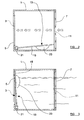
Figure 5 is an exploded perspective view of an embodiment of a vent according to the present invention; -
Figure 6 is a perspective view in more detail of a valve member forming part of the vent shown inFigure 5 ; -
Figure 7 is a perspective view of a float member forming part of the valve member shown inFigure 6 ; and -
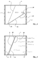
Figures 8 and 9 show the vent ofFigures 5 to 7 in use. - The vent shown in
Figures 1 to 3 comprises abody 1 having dimensions substantially corresponding to those of an air-brick. The body may be made, for example, of polypropylene, and may be made by injection moulding. A rear face of the body is formed with one ormore apertures 3, two rectangular apertures are shown inFigure 1 , which allow the passage of air into a building. The or eachaperture 3 is covered, ideally internally of the body, with amesh 5 to prevent insects or the like entering thebody 1 through the aperture(s) 3. The mesh may comprise, for example, extruded high-density polyethylene or polypropylene mesh having a mesh size of about 2 mm so as to offer protection against small insects while allowing good fluid flow. As an alternative, the mesh may be made of other materials, such as suitable plastics or non-corroding metals. The mesh may be incorporated into the body during moulding of the body, or may be attached subsequently, for example by means of threaded fasteners or an adhesive. - A front face of the
body 1 is substantially open and is covered with an aperturedpanel 7 which is secured to side walls of thebody 1 by means of suitable fasteners 9, such as threaded fasteners. Afurther mesh 11, essentially the same as themesh 5, is mounted between theapertured panel 7 and thebody 1, retained in position by the fasteners 9. The apertured panel may be made of the same material as thebody 1. - A
valve member 13, effectively in the form of a float controlled flap valve, is mounted within thebody 1 adjacent to the rear face of the body and comprises aplate 15 which has a substantially planar face for engaging with the rear face of the body so as to close the aperture(s) 3 in the rear face. If desired, the planar face of theplate 15 or the rear face of thebody 1 may be formed with a gasket (not shown) for sealing between the rear face and theplate 15. Thevalve member 13 is pivotably mounted in the lower side walls of thebody 1 by means of laterally-extendingpins 17 which extend from a lower edge of theplate 15 into arecess 19 provided in each side wall. Thepins 17 may form the ends of a substantiallycylindrical member 21 which extends along the lower edge of theplate 15 so as to strengthen the plate. Alternatively, theplate 15 may be provided with alternative strengthening means, such as reinforcing ribs provided on that side of the plate opposite to the planar face. Thevalve member 13 also includes afloat member 23 formed on that face of the plate opposite to the planar face. Thefloat member 23 reduces the specific gravity of thevalve member 13 to a value less than that of water, such that thevalve member 13 tends to rise when immersed in water, although in practice this is confined to pivoting movement due to the engagement between thevalve member 13 and thebody 1. Thevalve member 23 may be made of the same material as thebody 1, while the float member may be an air space or a foamed material provided within the material of theplate 15, for example as a bubble on that face of the plate remote from the planar face. - In use of the vent, the vent is incorporated into a wall of a building in the same manner as a conventional air-brick, with the
apertured panel 7 to the outside of the building. In normal conditions, air can pass between the outside and inside of the building through the apertured panel and the aperture(s) 3 formed in the rear face of thebody 1 as indicated by the arrows inFigure 2 . This is because, in the absence of water, thevalve member 13 pivots downwardly to rest on the base of thebody 1. However, in the event of flooding, ingress of water into thebody 1 causes thefloat member 23 to rise which results in pivoting of thevalve member 13 such that the planar face of theplate 15 bears against the rear face of thebody 1 to seal the aperture(s) 3 and prevent the flow of water through the body and into the building. In addition the pressure of the flood water against the plate of thevalve member 13 contributes to urging the plate against the rear face of the body and improves the seal between the plate and the body. - When the vent is intended for incorporation in a building during its construction, it may be preferred to provide at least some of the outer surfaces of the
body 1 with external grooves, ribs, lands, or other surface features which will assist in anchoring the vent in the cement, mortar or mastic used to hold it in place. On the other hand, when the vent is intended for incorporation in an existing building, it may be preferable to provide thebody 1 with substantially smooth outer surfaces so as to minimise the size of the opening required for insertion of the vent into the existing brickwork. - In the event of a flood, water may percolate through the soil beneath a building and cause dampness in any space below the ground floor. By temporarily removing the
apertured panel 7 andmesh 11, a larger aperture is available to assist in drying out such dampness, for example by inserting air hoses into the body. Once the dampness has been reduced to acceptable levels, for example by blowing in the air, the mesh and apertured panel can be replaced. - The vent shown in
Figure 4 is similar to that shown inFigures 1 to 3 and the same references are used to denote the same or similar components. For convenience, some components, such as the meshes are not shown inFigure 4 . In the embodiment ofFigure 4 the rear face of thebody 1 is inclined at an angle to the vertical such that the top of the rear face is closer to the front of the body than is the bottom thereof. The rear face may be inclined at an angle in the range from about 20 degrees to about 30 degrees, ideally substantially 22.5 degrees, to the vertical. The inclination of the rear face improves the seal between thebody 1 and theplate 15. - The vent according to the present invention and shown in
Figures 5 to 7 is similar to that shown in the previous figures and comprises abody 1 having arear face 2 formed with twoelongate apertures 3 which allow the passage of air into a building. The edges of the apertures may be chamfered for receiving closures as will be described in detail hereinafter. Therear face 2 is inclined at an angle of about 22.5 degrees to the vertical, with the top edge of the rear face being closer to the front of the body than the bottom thereof. Thebody 1 is a cuboid having a substantially rectangular cross section and presents front and rear edges which are covered with amesh 5 to prevent insects or the like entering thebody 1. The mesh may be a woven polyamide monofilament which is heat set and has about 14 threads per centimeter so as to offer protection against the passage of small insects while allowing good fluid flow. - The front and rear regions of the body are open and are each covered with an
apertured panel 7 which is secured to walls of thebody 1 by providing a stepped surface such that an inner region of thepanel 7 projects beyond an outer region, the step engaging with thebody 1. Themesh 5 is secured to the apertured panel by means of pins 9 which extend from the inner face of eachpanel 7 and pass through the mesh. - A
valve member 13, effectively in the form of a float controlled flap valve, is mounted within thebody 1 adjacent to the inclinedrear face 2 of the body and on that side thereof facing the front of the body. Thevalve member 13 comprises aplate 15 which has a substantially planar face for engaging against the inclined rear face of the body and to cover theapertures 3 in the rear face. Thevalve member 13 is pivotably mounted in the lower side walls of thebody 1 by means of laterally-extendingpins 17 which extend from the lower edge of theplate 15 into arecess 19 formed in each side wall. The pins may form the ends of a substantiallycylindrical member 21 which extends along the lower edge of theplate 15 so as to strengthen the plate. Theplate 15 is also provided with a pair ofaperture closures 25 which extend from the surface of theplate 15 and are dimensioned to fit closely within theapertures 3, theclosures 25 having chamfered edges such that the cross-sectional area of each closure increases towards the plate and the projections provide an increasingly tight fit with theapertures 3 as theplate 15 moves in use towards the rear face of the body. Theclosures 25 may be of the same material as the remainder of the plate or may be of an elastomeric material such as EPDM rubber. A plurality ofsmall apertures 27 are provided along the lower edge region of theplate 15 which allow any excess water between theplate 15 and the rear face of the body to escape as theplate 15 contacts therear face 2. - The
valve member 13 also includes a pair offloat members 23, for example positioned on the opposite side of theplate 15 and in substantially the same location as theclosures 25. Thefloat members 23 are made separately and are secured to theplate 15 in an air tight manner with a waterproof adhesive. The float members may be made of the same material as theplate 15. Thefloat members 23 reduce the specific gravity of thevalve member 13 to a value less than that of water, such that thevalve member 13 tends to rise when immersed in water, although in practice this is confined to pivoting movement due to engagement between thevalve member 13 and thebody 1. - Use of the vent of
Figures 5 to 7 is shown inFigures 8 and 9 and is essentially the same as the vent shown inFigures 1 to 3 .Figure 8 shows the vent in air and open, whileFigure 9 shows the vent in water and closed.
Claims (13)
- A vent comprising: a vent body (1); at least one air flow channel through the body between a front face and a rear face (2) of the body, the at least one air flow channel including at least one aperture (3) provided in the rear face of the body; and at least one flap valve (13) pivotably mounted within the body along a lower edge thereof, the or each valve having a first, normal position in which air is permitted to flow through an airflow channel and a second position in which the valve pivots in the presence of water to seal the air flow channel, wherein the valve (13) is mounted adjacent the rear face (2) of the body (1) and includes a plate (15) having a substantially planarface for engaging with the rear face (2) of the body (1), characterised in that the valve (13) is float controlled and in that the plate is provided with one or more aperture closures (25) projecting from the planar surface of the plate into the at least one aperture (3) in the rear face (2) in the second position of the valve, the one or more aperture closures being dimensioned to fit closely within the at least one aperture (3).
- A vent as claimed in claim 1, wherein the at least one flow channel includes one or more apertures (3) provided in the front face of the body (1).
- A vent as claimed in claim 2, wherein the edges of the aperture(s) (3) are chamfered.
- A vent as claimed in any preceding claim, wherein the body (1) has an apertured plate (7) covering the front and/or rear face (2) thereof.
- A vent as claimed in claim 2, 3 or 4, wherein the or each aperture (3) is covered with a mesh (5, 11) to prevent insects and the like entering the body (1).
- A vent as claimed in any preceding claim, wherein the edges of the projecting closure(s) (25) are chamfered.
- A vent as claimed in any preceding claim, wherein a gasket is provided for sealing between the flap valve (13) and the rear face (2) of the body (1).
- A vent as claimed in any preceding claim, wherein the flap valve (13) includes at least one float member (23).
- A vent as claimed in claim 8, wherein the at least one float member is provided on that face of the flap valve (13) remote from a sealing face thereof.
- A vent as claimed in any preceding claim, wherein a plurality of apertures (27) are provided along a lower edge region of the flap valve (13) to allow excess water to escape.
- A vent as claimed in any preceding claim, wherein the rearface (2) of the body (1) is inclined to the vertical such that the top of the rear face is closer to the front of the body than the bottom thereof.
- A vent as claimed in claim 11, wherein the rearface is inclined at an angle in the range from about 20 degrees to about 30 degrees to the vertical.
- A vent as claimed in claim 12, wherein the rearface is inclined at an angle of substantially 22.5 degrees to the vertical.
Applications Claiming Priority (3)
| Application Number | Priority Date | Filing Date | Title |
|---|---|---|---|
| GB0820069A GB0820069D0 (en) | 2008-11-01 | 2008-11-01 | Vent |
| GB0911934A GB0911934D0 (en) | 2009-07-09 | 2009-07-09 | Vent |
| PCT/EP2009/064062 WO2010060705A2 (en) | 2008-11-01 | 2009-10-26 | Vent |
Publications (3)
| Publication Number | Publication Date |
|---|---|
| EP2352894A2 EP2352894A2 (en) | 2011-08-10 |
| EP2352894B1 EP2352894B1 (en) | 2017-08-09 |
| EP2352894B9 true EP2352894B9 (en) | 2018-02-21 |
Family
ID=42226160
Family Applications (1)
| Application Number | Title | Priority Date | Filing Date |
|---|---|---|---|
| EP09740694.6A Active EP2352894B9 (en) | 2008-11-01 | 2009-10-26 | Vent |
Country Status (6)
| Country | Link |
|---|---|
| US (2) | US10301870B2 (en) |
| EP (1) | EP2352894B9 (en) |
| AU (1) | AU2009319240B2 (en) |
| CA (1) | CA2741924C (en) |
| ES (1) | ES2646116T3 (en) |
| WO (1) | WO2010060705A2 (en) |
Families Citing this family (21)
| Publication number | Priority date | Publication date | Assignee | Title |
|---|---|---|---|---|
| GB0919555D0 (en) * | 2009-11-09 | 2009-12-23 | Kelly John | Closable throughflow member |
| GB2479781A (en) * | 2010-04-23 | 2011-10-26 | Timloc Building Products Ltd | An air brick including an automatic flood seal |
| GB2480105B (en) * | 2010-05-07 | 2012-11-21 | Einstein Ip Ltd | Flood protection device |
| JP5792022B2 (en) * | 2011-10-19 | 2015-10-07 | 日立造船株式会社 | Wall-mounted flap gate waterproof panel |
| US8584411B2 (en) * | 2011-11-16 | 2013-11-19 | Alcoa Inc. | Floating flapper valve |
| EP2994577B1 (en) * | 2013-05-09 | 2020-07-08 | Floodbreak, LLC | Self-actuating flood guard |
| JP6227477B2 (en) * | 2014-05-16 | 2017-11-08 | 日立造船株式会社 | Pipe stop device |
| US20150362209A1 (en) | 2014-06-13 | 2015-12-17 | John T. Dolan | Insect barriers for inlets and vents |
| US9376803B1 (en) | 2015-04-08 | 2016-06-28 | Smart Vent Products, Inc. | Flood vent trigger systems |
| US9624637B2 (en) * | 2015-04-08 | 2017-04-18 | Smart Vent Products, Inc. | Flood vent |
| US10113309B2 (en) * | 2015-04-08 | 2018-10-30 | Smart Vent Products, Inc. | Flood vent barrier systems |
| GB201508712D0 (en) * | 2015-05-21 | 2015-07-01 | Univ Durham | Liquid movement and/or collection apparatus and method |
| US20160341442A1 (en) * | 2015-05-21 | 2016-11-24 | Brandon Murray | Multi-tap integrated duct assembly apparatus and method |
| GB2538718B (en) * | 2015-05-26 | 2017-08-16 | Vartanian Markar | A device for preventing the ingress of liquid |
| US10827652B2 (en) * | 2017-02-23 | 2020-11-03 | Cisco Technology, Inc. | Expandable rack mountable computing device |
| JP2019094750A (en) * | 2017-11-24 | 2019-06-20 | 田中 伸一 | Ventilation hole flooding prevention device |
| KR102003547B1 (en) * | 2018-05-03 | 2019-07-24 | 강승호 | Emergency Escape Apparatus of Ship |
| GB2584367B (en) * | 2019-05-28 | 2021-10-06 | Intumescent Systems Ltd | Cavity brick vent |
| CN111188451A (en) * | 2020-02-26 | 2020-05-22 | 水母(苏州)科技有限公司 | Intelligent hollow brick |
| JP7448434B2 (en) | 2020-07-16 | 2024-03-12 | 新日本空調株式会社 | Vertical water stop damper |
| CN113701331B (en) * | 2021-09-02 | 2024-09-06 | 珠海格力电器股份有限公司 | Air outlet frame of cabinet air conditioner and cabinet air conditioner with same |
Family Cites Families (14)
| Publication number | Priority date | Publication date | Assignee | Title |
|---|---|---|---|---|
| US2754747A (en) * | 1953-03-20 | 1956-07-17 | Herman G Bertling | Air register or louver |
| US5586934A (en) * | 1995-01-20 | 1996-12-24 | Dombrowski; Larry A. | Wall safe |
| US6485231B2 (en) * | 1997-07-10 | 2002-11-26 | Smart Vent, Inc. | Foundation flood gate with ventilation |
| US5916023A (en) * | 1997-07-18 | 1999-06-29 | Deflecto Corporation | Hooded exhaust vent |
| GB0018217D0 (en) * | 2000-07-26 | 2000-09-13 | Douglas George C | Apparatus for flooding protection |
| US6431980B1 (en) * | 2000-12-21 | 2002-08-13 | John J. Achen | Combustion air security vent |
| GB0301780D0 (en) | 2003-01-25 | 2003-02-26 | Taylor Andrew C | Vent |
| GB2410973A (en) * | 2004-02-14 | 2005-08-17 | Jack Tovey | Automatic flood barrier for a building vent |
| US7128643B2 (en) * | 2004-06-01 | 2006-10-31 | Aci Air Technologies, Llc | Removable vent having a filter for use in a building foundation |
| US8033900B2 (en) * | 2007-09-21 | 2011-10-11 | P-Tec Products, Inc. | Low profile animal restricting vent for fluid discharge conduits |
| GB0802544D0 (en) * | 2008-02-12 | 2008-03-19 | Mcnee John | Flood defender |
| AU2008100183A4 (en) | 2008-02-27 | 2008-05-08 | Kelly, Frank Mr | Smart Airbrick |
| GB2461754A (en) * | 2008-07-17 | 2010-01-20 | Frank Kelly | Air vent for use as an air brick with a float valve and insect mesh |
| US7926539B1 (en) * | 2008-10-31 | 2011-04-19 | Hurst Steven L | Flood vent access door assembly |
-
2009
- 2009-10-26 WO PCT/EP2009/064062 patent/WO2010060705A2/en active Application Filing
- 2009-10-26 CA CA2741924A patent/CA2741924C/en active Active
- 2009-10-26 EP EP09740694.6A patent/EP2352894B9/en active Active
- 2009-10-26 US US12/998,500 patent/US10301870B2/en active Active
- 2009-10-26 ES ES09740694.6T patent/ES2646116T3/en active Active
- 2009-10-26 AU AU2009319240A patent/AU2009319240B2/en active Active
-
2018
- 2018-12-14 US US16/221,310 patent/US10787857B2/en active Active
Also Published As
| Publication number | Publication date |
|---|---|
| US20120028564A1 (en) | 2012-02-02 |
| CA2741924C (en) | 2017-04-18 |
| EP2352894B1 (en) | 2017-08-09 |
| US10787857B2 (en) | 2020-09-29 |
| CA2741924A1 (en) | 2010-06-03 |
| WO2010060705A2 (en) | 2010-06-03 |
| ES2646116T3 (en) | 2017-12-12 |
| EP2352894A2 (en) | 2011-08-10 |
| WO2010060705A3 (en) | 2011-06-30 |
| US20190119975A1 (en) | 2019-04-25 |
| US10301870B2 (en) | 2019-05-28 |
| AU2009319240B2 (en) | 2016-04-28 |
| AU2009319240A1 (en) | 2010-06-03 |
Similar Documents
| Publication | Publication Date | Title |
|---|---|---|
| US10787857B2 (en) | Vent | |
| GB2461754A (en) | Air vent for use as an air brick with a float valve and insect mesh | |
| EP2499306B1 (en) | Closable throughflow member | |
| US6485231B2 (en) | Foundation flood gate with ventilation | |
| US6692187B2 (en) | Flood gate for door | |
| US7270498B1 (en) | Flood vent | |
| US9376803B1 (en) | Flood vent trigger systems | |
| AU2011249593B2 (en) | Flood protection device | |
| CA2775167A1 (en) | Door sill assembly for exterior doors | |
| AU2008230751A1 (en) | Ventilation sleeve for concrete foundation walls | |
| JP2011220048A (en) | Structure for preventing flood below floor level | |
| GB2397592A (en) | Air vent for use as an air brick | |
| GB2361733A (en) | Flexible curved flood barrier | |
| US10156072B2 (en) | Flood protection device | |
| US20120174501A1 (en) | Flood vent | |
| JP4511391B2 (en) | Aluminum joinery windproof device | |
| WO2002008533A1 (en) | Apparatus for flood prevention | |
| JP7260143B2 (en) | Underfloor ventilation structure | |
| JP4260644B2 (en) | Water stop structure at the joint of extruded cement board | |
| CN207513443U (en) | A kind of rainwater-proof windowsill component | |
| JP7300301B2 (en) | Underfloor ventilation system and house equipped with this underfloor ventilation system |
Legal Events
| Date | Code | Title | Description |
|---|---|---|---|
| PUAI | Public reference made under article 153(3) epc to a published international application that has entered the european phase |
Free format text: ORIGINAL CODE: 0009012 |
|
| 17P | Request for examination filed |
Effective date: 20110520 |
|
| AK | Designated contracting states |
Kind code of ref document: A2 Designated state(s): AT BE BG CH CY CZ DE DK EE ES FI FR GB GR HR HU IE IS IT LI LT LU LV MC MK MT NL NO PL PT RO SE SI SK SM TR |
|
| RIN1 | Information on inventor provided before grant (corrected) |
Inventor name: KELLY, FRANK |
|
| RAP1 | Party data changed (applicant data changed or rights of an application transferred) |
Owner name: KELMAR LIMITED |
|
| DAX | Request for extension of the european patent (deleted) | ||
| RAP1 | Party data changed (applicant data changed or rights of an application transferred) |
Owner name: BLUEWATER DESIGN ASSOCIATES LIMITED |
|
| 17Q | First examination report despatched |
Effective date: 20160610 |
|
| REG | Reference to a national code |
Ref country code: DE Ref legal event code: R079 Ref document number: 602009047638 Country of ref document: DE Free format text: PREVIOUS MAIN CLASS: E06B0009000000 Ipc: F24F0013080000 |
|
| GRAP | Despatch of communication of intention to grant a patent |
Free format text: ORIGINAL CODE: EPIDOSNIGR1 |
|
| RIC1 | Information provided on ipc code assigned before grant |
Ipc: F24F 13/20 20060101ALI20170131BHEP Ipc: F24F 13/08 20060101AFI20170131BHEP Ipc: F24F 7/00 20060101ALI20170131BHEP |
|
| INTG | Intention to grant announced |
Effective date: 20170307 |
|
| GRAS | Grant fee paid |
Free format text: ORIGINAL CODE: EPIDOSNIGR3 |
|
| GRAA | (expected) grant |
Free format text: ORIGINAL CODE: 0009210 |
|
| AK | Designated contracting states |
Kind code of ref document: B1 Designated state(s): AT BE BG CH CY CZ DE DK EE ES FI FR GB GR HR HU IE IS IT LI LT LU LV MC MK MT NL NO PL PT RO SE SI SK SM TR |
|
| REG | Reference to a national code |
Ref country code: GB Ref legal event code: FG4D |
|
| REG | Reference to a national code |
Ref country code: CH Ref legal event code: EP Ref country code: AT Ref legal event code: REF Ref document number: 917280 Country of ref document: AT Kind code of ref document: T Effective date: 20170815 |
|
| REG | Reference to a national code |
Ref country code: IE Ref legal event code: FG4D |
|
| REG | Reference to a national code |
Ref country code: DE Ref legal event code: R096 Ref document number: 602009047638 Country of ref document: DE |
|
| REG | Reference to a national code |
Ref country code: FR Ref legal event code: PLFP Year of fee payment: 9 |
|
| REG | Reference to a national code |
Ref country code: ES Ref legal event code: FG2A Ref document number: 2646116 Country of ref document: ES Kind code of ref document: T3 Effective date: 20171212 |
|
| REG | Reference to a national code |
Ref country code: NL Ref legal event code: MP Effective date: 20170809 |
|
| REG | Reference to a national code |
Ref country code: LT Ref legal event code: MG4D |
|
| REG | Reference to a national code |
Ref country code: AT Ref legal event code: MK05 Ref document number: 917280 Country of ref document: AT Kind code of ref document: T Effective date: 20170809 |
|
| PG25 | Lapsed in a contracting state [announced via postgrant information from national office to epo] |
Ref country code: HR Free format text: LAPSE BECAUSE OF FAILURE TO SUBMIT A TRANSLATION OF THE DESCRIPTION OR TO PAY THE FEE WITHIN THE PRESCRIBED TIME-LIMIT Effective date: 20170809 Ref country code: AT Free format text: LAPSE BECAUSE OF FAILURE TO SUBMIT A TRANSLATION OF THE DESCRIPTION OR TO PAY THE FEE WITHIN THE PRESCRIBED TIME-LIMIT Effective date: 20170809 Ref country code: SE Free format text: LAPSE BECAUSE OF FAILURE TO SUBMIT A TRANSLATION OF THE DESCRIPTION OR TO PAY THE FEE WITHIN THE PRESCRIBED TIME-LIMIT Effective date: 20170809 Ref country code: FI Free format text: LAPSE BECAUSE OF FAILURE TO SUBMIT A TRANSLATION OF THE DESCRIPTION OR TO PAY THE FEE WITHIN THE PRESCRIBED TIME-LIMIT Effective date: 20170809 Ref country code: LT Free format text: LAPSE BECAUSE OF FAILURE TO SUBMIT A TRANSLATION OF THE DESCRIPTION OR TO PAY THE FEE WITHIN THE PRESCRIBED TIME-LIMIT Effective date: 20170809 Ref country code: NO Free format text: LAPSE BECAUSE OF FAILURE TO SUBMIT A TRANSLATION OF THE DESCRIPTION OR TO PAY THE FEE WITHIN THE PRESCRIBED TIME-LIMIT Effective date: 20171109 Ref country code: NL Free format text: LAPSE BECAUSE OF FAILURE TO SUBMIT A TRANSLATION OF THE DESCRIPTION OR TO PAY THE FEE WITHIN THE PRESCRIBED TIME-LIMIT Effective date: 20170809 |
|
| PG25 | Lapsed in a contracting state [announced via postgrant information from national office to epo] |
Ref country code: BG Free format text: LAPSE BECAUSE OF FAILURE TO SUBMIT A TRANSLATION OF THE DESCRIPTION OR TO PAY THE FEE WITHIN THE PRESCRIBED TIME-LIMIT Effective date: 20171109 Ref country code: GR Free format text: LAPSE BECAUSE OF FAILURE TO SUBMIT A TRANSLATION OF THE DESCRIPTION OR TO PAY THE FEE WITHIN THE PRESCRIBED TIME-LIMIT Effective date: 20171110 Ref country code: LV Free format text: LAPSE BECAUSE OF FAILURE TO SUBMIT A TRANSLATION OF THE DESCRIPTION OR TO PAY THE FEE WITHIN THE PRESCRIBED TIME-LIMIT Effective date: 20170809 Ref country code: PL Free format text: LAPSE BECAUSE OF FAILURE TO SUBMIT A TRANSLATION OF THE DESCRIPTION OR TO PAY THE FEE WITHIN THE PRESCRIBED TIME-LIMIT Effective date: 20170809 Ref country code: IS Free format text: LAPSE BECAUSE OF FAILURE TO SUBMIT A TRANSLATION OF THE DESCRIPTION OR TO PAY THE FEE WITHIN THE PRESCRIBED TIME-LIMIT Effective date: 20171209 |
|
| PG25 | Lapsed in a contracting state [announced via postgrant information from national office to epo] |
Ref country code: DK Free format text: LAPSE BECAUSE OF FAILURE TO SUBMIT A TRANSLATION OF THE DESCRIPTION OR TO PAY THE FEE WITHIN THE PRESCRIBED TIME-LIMIT Effective date: 20170809 Ref country code: CZ Free format text: LAPSE BECAUSE OF FAILURE TO SUBMIT A TRANSLATION OF THE DESCRIPTION OR TO PAY THE FEE WITHIN THE PRESCRIBED TIME-LIMIT Effective date: 20170809 Ref country code: RO Free format text: LAPSE BECAUSE OF FAILURE TO SUBMIT A TRANSLATION OF THE DESCRIPTION OR TO PAY THE FEE WITHIN THE PRESCRIBED TIME-LIMIT Effective date: 20170809 |
|
| REG | Reference to a national code |
Ref country code: DE Ref legal event code: R097 Ref document number: 602009047638 Country of ref document: DE |
|
| PG25 | Lapsed in a contracting state [announced via postgrant information from national office to epo] |
Ref country code: SK Free format text: LAPSE BECAUSE OF FAILURE TO SUBMIT A TRANSLATION OF THE DESCRIPTION OR TO PAY THE FEE WITHIN THE PRESCRIBED TIME-LIMIT Effective date: 20170809 Ref country code: EE Free format text: LAPSE BECAUSE OF FAILURE TO SUBMIT A TRANSLATION OF THE DESCRIPTION OR TO PAY THE FEE WITHIN THE PRESCRIBED TIME-LIMIT Effective date: 20170809 Ref country code: IT Free format text: LAPSE BECAUSE OF FAILURE TO SUBMIT A TRANSLATION OF THE DESCRIPTION OR TO PAY THE FEE WITHIN THE PRESCRIBED TIME-LIMIT Effective date: 20170809 Ref country code: SM Free format text: LAPSE BECAUSE OF FAILURE TO SUBMIT A TRANSLATION OF THE DESCRIPTION OR TO PAY THE FEE WITHIN THE PRESCRIBED TIME-LIMIT Effective date: 20170809 Ref country code: MC Free format text: LAPSE BECAUSE OF FAILURE TO SUBMIT A TRANSLATION OF THE DESCRIPTION OR TO PAY THE FEE WITHIN THE PRESCRIBED TIME-LIMIT Effective date: 20170809 |
|
| REG | Reference to a national code |
Ref country code: CH Ref legal event code: PL |
|
| PLBE | No opposition filed within time limit |
Free format text: ORIGINAL CODE: 0009261 |
|
| STAA | Information on the status of an ep patent application or granted ep patent |
Free format text: STATUS: NO OPPOSITION FILED WITHIN TIME LIMIT |
|
| REG | Reference to a national code |
Ref country code: DE Ref legal event code: R081 Ref document number: 602009047638 Country of ref document: DE Owner name: M3 FLOODTEC HOLDINGS LTD., DROITWICH, GB Free format text: FORMER OWNER: BLUEWATER DESIGN ASSOCIATES LTD., RASHWOOD DROITWICH, WORCESTERSHIRE, GB Ref country code: DE Ref legal event code: R081 Ref document number: 602009047638 Country of ref document: DE Owner name: M3 GLOBAL FLOOD TECHNOLOGIES LTD., HORSHAM, GB Free format text: FORMER OWNER: BLUEWATER DESIGN ASSOCIATES LTD., RASHWOOD DROITWICH, WORCESTERSHIRE, GB Ref country code: DE Ref legal event code: R082 Ref document number: 602009047638 Country of ref document: DE Representative=s name: LUEDCKE, JOACHIM MORITZ, DIPL.-ING., DE Ref country code: DE Ref legal event code: R081 Ref document number: 602009047638 Country of ref document: DE Owner name: DRINAGH DESIGN LTD., BLACKROCK, IE Free format text: FORMER OWNER: BLUEWATER DESIGN ASSOCIATES LTD., RASHWOOD DROITWICH, WORCESTERSHIRE, GB |
|
| 26N | No opposition filed |
Effective date: 20180511 |
|
| REG | Reference to a national code |
Ref country code: DE Ref legal event code: R081 Ref document number: 602009047638 Country of ref document: DE Owner name: M3 FLOODTEC HOLDINGS LTD., DROITWICH, GB Free format text: FORMER OWNER: DRINAGH DESIGN LTD., DUBLIN, IE Ref country code: DE Ref legal event code: R081 Ref document number: 602009047638 Country of ref document: DE Owner name: M3 GLOBAL FLOOD TECHNOLOGIES LTD., HORSHAM, GB Free format text: FORMER OWNER: DRINAGH DESIGN LTD., DUBLIN, IE Ref country code: DE Ref legal event code: R082 Ref document number: 602009047638 Country of ref document: DE Representative=s name: LUEDCKE, JOACHIM MORITZ, DIPL.-ING., DE Ref country code: DE Ref legal event code: R081 Ref document number: 602009047638 Country of ref document: DE Owner name: DRINAGH DESIGN LTD., BLACKROCK, IE Free format text: FORMER OWNER: DRINAGH DESIGN LTD., DUBLIN, IE |
|
| PG25 | Lapsed in a contracting state [announced via postgrant information from national office to epo] |
Ref country code: LU Free format text: LAPSE BECAUSE OF NON-PAYMENT OF DUE FEES Effective date: 20171026 Ref country code: CH Free format text: LAPSE BECAUSE OF NON-PAYMENT OF DUE FEES Effective date: 20171031 Ref country code: LI Free format text: LAPSE BECAUSE OF NON-PAYMENT OF DUE FEES Effective date: 20171031 |
|
| REG | Reference to a national code |
Ref country code: GB Ref legal event code: 732E Free format text: REGISTERED BETWEEN 20180709 AND 20180711 |
|
| REG | Reference to a national code |
Ref country code: FR Ref legal event code: TP Owner name: DRINAGH DESIGN LIMITED, IE Effective date: 20180711 |
|
| REG | Reference to a national code |
Ref country code: BE Ref legal event code: MM Effective date: 20171031 |
|
| PG25 | Lapsed in a contracting state [announced via postgrant information from national office to epo] |
Ref country code: BE Free format text: LAPSE BECAUSE OF NON-PAYMENT OF DUE FEES Effective date: 20171031 Ref country code: SI Free format text: LAPSE BECAUSE OF FAILURE TO SUBMIT A TRANSLATION OF THE DESCRIPTION OR TO PAY THE FEE WITHIN THE PRESCRIBED TIME-LIMIT Effective date: 20170809 |
|
| REG | Reference to a national code |
Ref country code: ES Ref legal event code: PC2A Owner name: DRINAGH DESING LIMITED Effective date: 20180918 |
|
| PG25 | Lapsed in a contracting state [announced via postgrant information from national office to epo] |
Ref country code: MT Free format text: LAPSE BECAUSE OF NON-PAYMENT OF DUE FEES Effective date: 20171026 |
|
| REG | Reference to a national code |
Ref country code: FR Ref legal event code: PLFP Year of fee payment: 10 |
|
| REG | Reference to a national code |
Ref country code: ES Ref legal event code: PC2A Owner name: M3 GLOBAL FLOOD TECHNOLOGIES LIMITED Effective date: 20190402 |
|
| REG | Reference to a national code |
Ref country code: GB Ref legal event code: 732E Free format text: REGISTERED BETWEEN 20190314 AND 20190320 |
|
| REG | Reference to a national code |
Ref country code: DE Ref legal event code: R081 Ref document number: 602009047638 Country of ref document: DE Owner name: M3 FLOODTEC HOLDINGS LTD., DROITWICH, GB Free format text: FORMER OWNER: DRINAGH DESIGN LTD., BLACKROCK, COUNTY DUBLIN, IE Ref country code: DE Ref legal event code: R082 Ref document number: 602009047638 Country of ref document: DE Representative=s name: LUEDCKE, JOACHIM MORITZ, DIPL.-ING., DE Ref country code: DE Ref legal event code: R081 Ref document number: 602009047638 Country of ref document: DE Owner name: M3 GLOBAL FLOOD TECHNOLOGIES LTD., HORSHAM, GB Free format text: FORMER OWNER: DRINAGH DESIGN LTD., BLACKROCK, COUNTY DUBLIN, IE |
|
| PG25 | Lapsed in a contracting state [announced via postgrant information from national office to epo] |
Ref country code: HU Free format text: LAPSE BECAUSE OF FAILURE TO SUBMIT A TRANSLATION OF THE DESCRIPTION OR TO PAY THE FEE WITHIN THE PRESCRIBED TIME-LIMIT; INVALID AB INITIO Effective date: 20091026 |
|
| PG25 | Lapsed in a contracting state [announced via postgrant information from national office to epo] |
Ref country code: CY Free format text: LAPSE BECAUSE OF NON-PAYMENT OF DUE FEES Effective date: 20170809 |
|
| PG25 | Lapsed in a contracting state [announced via postgrant information from national office to epo] |
Ref country code: MK Free format text: LAPSE BECAUSE OF FAILURE TO SUBMIT A TRANSLATION OF THE DESCRIPTION OR TO PAY THE FEE WITHIN THE PRESCRIBED TIME-LIMIT Effective date: 20170809 |
|
| PG25 | Lapsed in a contracting state [announced via postgrant information from national office to epo] |
Ref country code: TR Free format text: LAPSE BECAUSE OF FAILURE TO SUBMIT A TRANSLATION OF THE DESCRIPTION OR TO PAY THE FEE WITHIN THE PRESCRIBED TIME-LIMIT Effective date: 20170809 |
|
| PG25 | Lapsed in a contracting state [announced via postgrant information from national office to epo] |
Ref country code: PT Free format text: LAPSE BECAUSE OF FAILURE TO SUBMIT A TRANSLATION OF THE DESCRIPTION OR TO PAY THE FEE WITHIN THE PRESCRIBED TIME-LIMIT Effective date: 20170809 |
|
| REG | Reference to a national code |
Ref country code: GB Ref legal event code: 732E Free format text: REGISTERED BETWEEN 20220915 AND 20220921 |
|
| REG | Reference to a national code |
Ref country code: ES Ref legal event code: PC2A Owner name: M3 FLOODTEC HOLDINGS LIMITED Effective date: 20221010 |
|
| REG | Reference to a national code |
Ref country code: DE Ref legal event code: R081 Ref document number: 602009047638 Country of ref document: DE Owner name: M3 FLOODTEC HOLDINGS LTD., DROITWICH, GB Free format text: FORMER OWNER: M3 GLOBAL FLOOD TECHNOLOGIES LTD., HORSHAM, WEST SUSSEX, GB |
|
| PGFP | Annual fee paid to national office [announced via postgrant information from national office to epo] |
Ref country code: IE Payment date: 20230822 Year of fee payment: 15 |
|
| PGFP | Annual fee paid to national office [announced via postgrant information from national office to epo] |
Ref country code: GB Payment date: 20231004 Year of fee payment: 15 |
|
| PGFP | Annual fee paid to national office [announced via postgrant information from national office to epo] |
Ref country code: ES Payment date: 20231102 Year of fee payment: 15 |
|
| PGFP | Annual fee paid to national office [announced via postgrant information from national office to epo] |
Ref country code: FR Payment date: 20231024 Year of fee payment: 15 Ref country code: DE Payment date: 20230824 Year of fee payment: 15 |