EP2352432B1 - Cone beam z-axis coverage - Google Patents
Cone beam z-axis coverage Download PDFInfo
- Publication number
- EP2352432B1 EP2352432B1 EP09760600.8A EP09760600A EP2352432B1 EP 2352432 B1 EP2352432 B1 EP 2352432B1 EP 09760600 A EP09760600 A EP 09760600A EP 2352432 B1 EP2352432 B1 EP 2352432B1
- Authority
- EP
- European Patent Office
- Prior art keywords
- cone angle
- anode
- angle
- focal spot
- radiation
- Prior art date
- Legal status (The legal status is an assumption and is not a legal conclusion. Google has not performed a legal analysis and makes no representation as to the accuracy of the status listed.)
- Active
Links
- 230000005855 radiation Effects 0.000 claims description 57
- 230000000694 effects Effects 0.000 claims description 20
- 238000002591 computed tomography Methods 0.000 claims description 16
- 238000003384 imaging method Methods 0.000 claims description 12
- 238000000034 method Methods 0.000 claims description 7
- 230000002238 attenuated effect Effects 0.000 claims description 5
- 230000035945 sensitivity Effects 0.000 claims description 3
- 230000000670 limiting effect Effects 0.000 description 9
- 210000000056 organ Anatomy 0.000 description 8
- 230000002829 reductive effect Effects 0.000 description 4
- 238000007408 cone-beam computed tomography Methods 0.000 description 2
- 230000003247 decreasing effect Effects 0.000 description 2
- 238000004088 simulation Methods 0.000 description 2
- 230000003068 static effect Effects 0.000 description 2
- 229920003266 Leaf® Polymers 0.000 description 1
- 230000000747 cardiac effect Effects 0.000 description 1
- 239000002131 composite material Substances 0.000 description 1
- 239000002872 contrast media Substances 0.000 description 1
- 238000001514 detection method Methods 0.000 description 1
- 238000010894 electron beam technology Methods 0.000 description 1
- 230000004907 flux Effects 0.000 description 1
- 238000010438 heat treatment Methods 0.000 description 1
- 208000014674 injury Diseases 0.000 description 1
- 230000003993 interaction Effects 0.000 description 1
- 230000001678 irradiating effect Effects 0.000 description 1
- 230000001788 irregular Effects 0.000 description 1
- 230000010412 perfusion Effects 0.000 description 1
- 239000007787 solid Substances 0.000 description 1
- 230000008733 trauma Effects 0.000 description 1
Images

Classifications
-
- A—HUMAN NECESSITIES
- A61—MEDICAL OR VETERINARY SCIENCE; HYGIENE
- A61B—DIAGNOSIS; SURGERY; IDENTIFICATION
- A61B6/00—Apparatus for radiation diagnosis, e.g. combined with radiation therapy equipment
- A61B6/02—Devices for diagnosis sequentially in different planes; Stereoscopic radiation diagnosis
- A61B6/03—Computerised tomographs
- A61B6/032—Transmission computed tomography [CT]
-
- A—HUMAN NECESSITIES
- A61—MEDICAL OR VETERINARY SCIENCE; HYGIENE
- A61B—DIAGNOSIS; SURGERY; IDENTIFICATION
- A61B6/00—Apparatus for radiation diagnosis, e.g. combined with radiation therapy equipment
- A61B6/40—Apparatus for radiation diagnosis, e.g. combined with radiation therapy equipment with arrangements for generating radiation specially adapted for radiation diagnosis
- A61B6/4064—Apparatus for radiation diagnosis, e.g. combined with radiation therapy equipment with arrangements for generating radiation specially adapted for radiation diagnosis specially adapted for producing a particular type of beam
- A61B6/4085—Cone-beams
-
- A—HUMAN NECESSITIES
- A61—MEDICAL OR VETERINARY SCIENCE; HYGIENE
- A61B—DIAGNOSIS; SURGERY; IDENTIFICATION
- A61B6/00—Apparatus for radiation diagnosis, e.g. combined with radiation therapy equipment
- A61B6/52—Devices using data or image processing specially adapted for radiation diagnosis
- A61B6/5258—Devices using data or image processing specially adapted for radiation diagnosis involving detection or reduction of artifacts or noise
-
- A—HUMAN NECESSITIES
- A61—MEDICAL OR VETERINARY SCIENCE; HYGIENE
- A61B—DIAGNOSIS; SURGERY; IDENTIFICATION
- A61B6/00—Apparatus for radiation diagnosis, e.g. combined with radiation therapy equipment
- A61B6/40—Apparatus for radiation diagnosis, e.g. combined with radiation therapy equipment with arrangements for generating radiation specially adapted for radiation diagnosis
- A61B6/4021—Apparatus for radiation diagnosis, e.g. combined with radiation therapy equipment with arrangements for generating radiation specially adapted for radiation diagnosis involving movement of the focal spot
-
- A—HUMAN NECESSITIES
- A61—MEDICAL OR VETERINARY SCIENCE; HYGIENE
- A61B—DIAGNOSIS; SURGERY; IDENTIFICATION
- A61B6/00—Apparatus for radiation diagnosis, e.g. combined with radiation therapy equipment
- A61B6/52—Devices using data or image processing specially adapted for radiation diagnosis
- A61B6/5258—Devices using data or image processing specially adapted for radiation diagnosis involving detection or reduction of artifacts or noise
- A61B6/5282—Devices using data or image processing specially adapted for radiation diagnosis involving detection or reduction of artifacts or noise due to scatter
Definitions
- CT cone beam computed tomography
- a cone-beam computed tomography (CT) scanner generally includes an x-ray tube and a two-dimensional detector array, which are affixed on a rotor on opposite sides of an examination region.
- the rotor is rotatably supported by a stationary frame and rotates about a longitudinal or z-axis around the examination region, thereby rotating the x-ray tube and the detector array about the longitudinal axis and around the examination region.
- the x-ray tube emits radiation, from a focal spot on an anode of the tube, that traverses the examination region and illuminates the detector array.
- a source collimator collimates the emitted radiation so that a generally cone-shaped radiation beam traverses the examination region.
- a patient support supports an object or subject in the examination region
- the angle of the cone beam along the longitudinal axis defines a z-axis width or scan coverage and has been referred to as the cone angle.
- the extent of the cone angle is limited by the heel effect, which is a function of the anode angle (e.g., typically eight degrees (8°)).
- Rays emanating from the side of the beam closer to the anode, with respect to a center ray of the beam, are attenuated and hardened relative to rays emanating from the side of beam closer to the cathode.
- the intensities of the rays on the anode side are less than the intensities of the rays on the cathode side, with the hardening and drop in intensity and an increase in the mean energy increasing as the angle increase in the direction of the anode.
- the anode angle generally defines an effective maximum cone angle in that the intensity and energy of rays for larger angles generally are not suitable for CT applications.
- the anode angle defines an effective maximum volume or z-axis coverage that can be scanned at any moment in time.
- this volume may not be enough for certain scans, such as scans covering an entire organ such as the entire heart without having to translate the radiation beam or the patient in the z-axis direction.
- scan time may be increased and the resulting data for a whole organ scan may include motion artifact.
- an x-ray tube with a larger anode angle e.g., twelve degrees (12°) has been used to increase the effective maximum volume or z-axis coverage.
- increasing the anode angle also may reduce the focal spot size on the anode, the power rating of the x-ray tube and imaging resolution and increases cone beam artifact.
- the z-axis scan coverage may still not be enough to cover an entire organ without having to translate the radiation beam or the patient in the z-axis direction.
- WO 2004/075118 A1 discloses a multislice computed tomography scanner for imaging a patient.
- the multislice computed tomography scanner comprises an x-ray source that generates a cone beam of x-rays radiated from a focal spot of the x-ray source, wherein the x-ray source is movable in a rotation plane so as to rotate the focal spot about an axial direction, along which the patient is moved to position the patient in a field of view of the scanner.
- the multislice computed tomography scanner further comprises a detector array with a plurality of rows of x-ray detectors that generate signals responsive to x-rays in the cone beam, which signals are used to generate an image of the patient.
- the cone beam is asymmetric with respect to the rotation plane.
- US 2008/0123816 A1 discloses a heel effect compensation filter configured to have a thickness distribution that uniforms an x-ray intensity angular distribution that is nonuniform in a body axis direction of a subject in an x-ray flux irradiated space.
- US 6,330,299 B1 discloses semi-transparent beam filters like shutter leafs with tapered thickness and irregular width shapes that vary in position and angle with user selection and x-ray tube heel effect. The article " An improved analytical model for CT dose simulation with a new look at the theory of CT dose" by R.
- the rotating gantry 104 supports a radiation source 110, such as an x-ray tube.
- the radiation source 110 includes an eight degree (8°) anode (not visible) and emits radiation from a focal spot (not visible) thereon.
- the emitted radiation traverses the examination region 106 and any object or subject dispose therein.
- the focal spot emits radiation while the rotating gantry 104, and hence the radiation source 110 and the focal spot, rotate around the z-axis 108 during a helical or axial scan or are at a static position for a pilot or scout scan.
- the focal spot can translate along the z-axis physically, for example, by translating the radiation source 110 along the z-axis, and/or electronically.
- the focal spot translates in coordination with motion of an object such as an organ like the heart disposed within the examination region 106 or a flow of a contrast agent or the like through an object disposed within the examination region 106.
- Such coordination can be in connection with fly-by scanning in which the radiation source 110 physically translates along the z-axis 108. Examples of such scanning are discussed at least in patent application serial no. PCT/US07/78130, filed September 11, 2007 , and entitled “Fly-By Scanning," and published as WO2008/042564 .
- a source collimator 112 translates in coordination with the radiation source 110 and collimates the emitted radiation in the z-axis direction to produce a generally conical shaped radiation beam that traverses the examination region 106.
- the collimator 112 includes at least one collimator blade 114 configured to translate in the z-axis direction, relative to the radiation source 110.
- the illustrated scanner 100 includes N collimator blades 114, wherein N is two (2). In other embodiments, N can be more or less than two (2).
- the source collimator 112 is employed to produce a cone beam, which has a cone angle along the z-axis that defines the z-axis width or scan coverage.
- the source collimator 112 increases the effective maximum cone-beam angle in both directions along the z-axis. This may include symmetrically or asymmetrically increasing the cone beam angle in both directions along the z-axis about an imaginary axis that extends perpendicularly from the focal spot through a center region of the examination region 106 through the z-axis 108.
- the z-axis coverage can be expanded while maintaining the same radiation source power, relative to a configuration where the cone beam angle is not increased beyond the effective maximum cone-beam angle, which generally is defined by the angle of the anode (not visible) of the radiation source 110.
- a controller 115 controls the source collimator 112 based on a scan protocol, including, but not limited to, a fly by scan or other scan protocol, and/or otherwise.
- the rotating gantry 104 also supports a radiation sensitive detector array 116, which is disposed about the rotating gantry portion 104 and subtends an angular arc opposite the radiation source 110.
- the detector array 116 includes a multi-slice detector having a plurality of detector elements extending in the axial and transverse directions. Each detector element detects radiation emitted by the radiation source 110 that traverses the examination region 106 for at least one hundred and eighty degrees (180°) plus a fan angle of data, and generates a corresponding output signal or projection data indicative of the detected radiation.
- a non-limiting example of a suitable detector includes a tile detector as are described in US patent 6,510,195 B1 to Chappo et al., filed July 18, 2001 , and entitled "Solid State X-Radiation Detector Modules and Mosaics Thereof, and an Imaging Method and Apparatus Employing the Same".
- a one or two dimensional anti-scatter grid may be employed in connection with the detector array 116 to mitigate or reduce detection of scatter radiation.
- the projection data generated by the detector array 116 are conveyed to a reconstructor 118, which reconstructs the projections and generates volumetric image data.
- the image data can be processed by an image processor to generate one or more images of the scanned region of interest or a subset thereof.
- a data corrector 120 can be used to correct the data for reconstruction. In one instance, this includes applying a correction that reduces the heel effect by providing a correction for increased attenuation and/or beam hardening. Such a correction may be used when the employed cone beam angle exceeds the effective maximum cone beam angle, as defined by the anode angle. As the heel effect varies along the z-axis, the correction may vary along the z-axis, with the largest correction generally being applied to the end ray(s) on the heel side of the cone beam.
- An operator console 122 facilitates user interaction with the imaging system 100.
- Software applications executed by the operator console 122 allow the user to configure and/or control operation of the imaging system 100. For instance, the user can interact with the operator console 122 to select a fly-by or other scan protocol, and initiate, pause and/or terminate a scan, etc.
- a couch or patient support 124 supports an object or subject such as a human or animal within the examination region 106.
- the support 124 can be movable, which enables an operator or the system to suitably position the object or subject within the examination region 106 before, during and/or after scanning.
- the above system 100 can be employed for various applications.
- the system 100 is suited for whole organ scanning, such as scanning the entire heart or a substantial portion thereof in a single heart beat, if desired.
- a scan may be a fly-by or other scan performed with a radiation source having an eight degree (8°) or other angle anode, using full radiation source power for coverage between eight (8) to forty (40) centimeters (cm), such as 8 cm, 9 cm, 10 cm, 11 cm, 12 cm, etc. scans with minimal to substantially no motion artifacts and minimal to substantially no cone beam artifacts.
- a fly-by scan sufficient coverage can be obtained without sacrificing power and image quality.
- the illustrated radiation source 110 can include an eight degree (8°) anode.
- FIGURE 2 illustrates such an anode 202 in connection with collimator blades 114 1 and 114 2 .
- the collimator blades 114 1 and 114 2 are opened to form a cone angle of eight degrees (8°), with a magnitude of four (4) degrees on each side of an axis 204, which extends perpendicularly from a focal spot 206 through the z-axis 108.
- the detector array 116 includes one hundred and twenty eight (128) rows of detector pixels along the z-axis 108, where each pixel is about 0.625 mm. Of course, more or less rows and/or other size pixels can be used in other embodiments.
- the anode angle defines an effective maximum cone angle of a cone beam 208 that is symmetric about the axis 204, as the heel effect attenuates and hardens beam rays emanating from the focal spot 206 on the anode side of the axis 204 when the cone angle is greater than the effective maximum cone angle.
- the intensity of the rays substantially falls off and the rays are substantially attenuated such that the intensity and energy of the rays generally are not effective for CT applications.
- Such data does not render diagnostic data while still irradiating the patient.
- this angle is about eight degrees (8°), or four degrees (4°) on each side of the axis 204.
- the collimator blades 114 can be positioned to substantially or completely collimate rays emanating from the focal spot 206 at an angle greater than the effective maximum cone angle.
- the radiation source 110 can be operated at full power, with local heating from an electron beam 210 spread about the anode 202 as the anode 202 rotates and spread radially along the anode 202 slope.
- the effective focal spot size, as seen at the detector array 116 is small enough so as to maintain a suitable resolution along the z-axis, while providing suitable z-axis coverage and maximizing radiation source power.
- the collimator blades 114 1 and 114 2 of the system 100 can be symmetrically opened to allow for a larger angle cone beam.
- the collimator blades 114 1 and 114 2 are opened to increase the cone angle from eight degrees (8°), as shown in FIGURE 2 , to about ten degrees (10°), with five degrees (5°) on each side of the axis 204.
- a resulting beam 302 has an expanded width along the z-axis, allowing for more rows of detector pixels, such as, for example, one hundred and sixty (160) rows of detector pixels, where each pixel is about 0.625 mm.
- helical cone beam scans with extended z-axis coverage for example, up to ten centimeters (10 cm) can be performed while maintaining radiation source power, without introducing significantly greater cone beam artifacts and/or decreasing resolution.
- scan time and/or motion artifacts can be reduced.
- more or less rows and/or other size pixels can be used in other embodiments.
- the coverage is smaller, and with a system with a larger anode angle so as to achieve 10 cm of coverage, tube power must reduced, which may reduce image quality.
- the collimator blades 114 1 and 114 2 are asymmetrically opened to allow for a larger angle cone beam.
- the collimator blades 114 1 and 114 2 are asymmetrically opened to increase the cone angle from eight degrees (8°), as shown in FIGURE 2 , to twelve degrees (12°), with five degrees (5°) on the heel side of the axis 204 and seven degrees (7°) on the other side of the axis 204.
- a resulting beam 402 has an expanded width along the z-axis, allowing for more rows of detector pixels, such as, for example, one hundred and ninety-two (192) rows of detector pixels, where each pixel is about 0.625 mm.
- helical cone beam scans with extended z-axis coverage can be performed while maintaining radiation source power, without significantly increasing cone beam artifacts and/or decreasing resolution, and possibly reducing scan time and/or motion artifacts.
- the extended cone beam provides fifty percent (50%) more coverage for the same radiation source power used in connection with the embodiment of FIGURE 2 .
- more or less rows and/or other size pixels can be used in other embodiments.
- the coverage is smaller, and with a system with a larger anode angle so as to achieve 12 cm of coverage, tube power must reduced, which may reduce image quality.
- only the collimator blade 114 1 on the anode 202 side is opened to increase the cone beam angel larger then the effective maximum cone beam angle as determined by the heel effect and anode angle.
- the collimator blade 114 1 may be opened from one (1) to three (3) centimeters. Again, relative to the configuration shown in FIGURE 2 , the resulting beam has an expanded width along the z-axis. Furthermore, a beam hardening or heel correction is applied to compensate for beam hardening artifact.
- the above system 100 can be employed for various applications.
- the system 100 is suited for whole organ scanning, such as scanning the entire heart or a substantial portion thereof in a single heart beat, if desired.
- a scan may be a fly-by or other scan performed with a radiation source having an eight degree (8°) or other angle anode, using full radiation source power for coverage between eight centimeters (8 cm) to forty centimeters (40 cm), such as 8 cm, 9 cm, 10 cm, 11 cm, 12 cm, etc. centimeters scans with minimal to substantially no motion artifacts and minimal to substantially no cone beam artifacts.
- a fly-by scan sufficient coverage can be obtained without sacrificing power and image quality.
- radiation sources with larger or smaller anode angles and/or cone beams with larger or smaller symmetric or asymmetric cone angles are contemplated.
- suitable anode angles range from seven (7) to twelve (12) degree angles correspond to suitable extended cone beam angles up to ten (10) to twenty (20) degree angles, etc.
- the imaging system 100 can be used for various applications, including helical and/or axial scans.
- cone beam artifacts are smaller (e.g., less than twenty percent (20%)) for helical scans relative to axial scans, and for some helical scans, the cone beam artifacts are minimal.
- FIGURE 5 shows a cone beam 502 at a first position 504 and a second position 506, which is one hundred and eighty (180) degrees offset from the first position 504.
- the anode angle is eight degrees (8°) and the collimator blades 114 are positioned so that the cone beam has a twelve degree (12°) angle, as shown in connection with FIGURE 4 above.
- the pitch factor is one and three quarters (1.75).
- a distance 508 between a ray 510 extending perpendicularly from a focal spot through the z-axis 108 at the positions 504, 506 is about ten and a half centimeters (10.5 cm), and a relative angle 512 between the beam 502 at the two positions 504, 506 is less than one and eight tenths degrees (1.8°).
- Slice sensitivity is also generally more uniform for helical scans relative to axial scans. That is, for a given voxel in a helical reconstruction, the z-axis response will vary from about sixty percent (60%) of a nominal size to about one hundred and eighty-eight percent (188%) of the nominal size when the collimator blades 114 are positioned for a cone beam with an extended cone angle of twelve degrees (12°), as illustrated in FIGURE 4 .
- the size of a given voxel at the center of the cone will be about half a millimeter (0.5 mm), whereas the size of the voxel on the heel side of the axis 204 will be about three tenths of a millimeter (0.3 mm) and the size of the voxel on the other side of the axis will be about nine tenths of a millimeter (0.9 mm).
- the nominal size of the voxel will be the composite of the foregoing responses. As such, all voxels may have about the same nominal slice width sensitivity.
- the collimator blades 114 can be positioned to increase z-axis coverage without reducing or sacrificing radiation source power or resolution or significantly increasing cone beam artifacts, noting that a heel effect correction may be performed on the data to correct for both increased attenuation and beam hardening, relative to an embodiment in which the collimator blades 114 are positioned based on the effective maximum cone angle defined by the anode angle, which assumes a maximum heel angle of 4 degrees for an 8 degree anode.
- Example operation of the system 100 is discussed in connection with FIGURE 6 . It is to be appreciated that the order of the following acts is not limiting and may otherwise occur. In addition, more or less, including similar or different acts may be employed in other embodiments.
- a cone beam having an extended cone angle along the z-axis and thus an extended z-axis scan coverage is produced.
- this may include symmetrically or asymmetrically opening the collimator blades 114 about the central ray axis 204 so as to produce a cone beam with a cone angle that is larger than the effective maximum cone angle determined by the anode angle.
- a scan is performed with the cone beam.
- a scan may be a helical scan such as a fly by or other scan, an axial scan, and/or another scan.
- the scan can involve scanning an entire organ, such as a static or moving organ, without having to move or substantially move the radiation source 110 and/or the object or subject being scanned.
- the radiation source power is maintained at a power level such as full power as if the cone beam angle is not extended, but equal to the effective maximum cone beam angle. In one instance, this may be defined by 2( ⁇ -4).
- an optional heel effect correction is applied.
- Such a correction can be applied to the raw data, the reconstructed volumetric image data, and/or one or more images generated as part of the reconstructed volumetric image data.
- the above may be implemented by way of computer readable instructions, which when executed by a computer processor(s), cause the processor(s) to carry out the foregoing.
- the instructions are stored in a computer readable storage medium associated with or otherwise accessible to a relevant computer, such as a dedicated workstation, a home computer, a distributed computing system, the console, and/or other computer.
- a relevant computer such as a dedicated workstation, a home computer, a distributed computing system, the console, and/or other computer.
- the acts need not be performed concurrently with data acquisition.
- the above may be used in various applications including applications where it may be desirable to achieve relatively large coverage in a relatively short period of time without moving the patient support such as for cardiac, trauma, perfusion and/or other applications.
Description
- The following generally relates to cone beam computed tomography (CT).
- A cone-beam computed tomography (CT) scanner generally includes an x-ray tube and a two-dimensional detector array, which are affixed on a rotor on opposite sides of an examination region. The rotor is rotatably supported by a stationary frame and rotates about a longitudinal or z-axis around the examination region, thereby rotating the x-ray tube and the detector array about the longitudinal axis and around the examination region. The x-ray tube emits radiation, from a focal spot on an anode of the tube, that traverses the examination region and illuminates the detector array. A source collimator collimates the emitted radiation so that a generally cone-shaped radiation beam traverses the examination region. A patient support supports an object or subject in the examination region
- The angle of the cone beam along the longitudinal axis defines a z-axis width or scan coverage and has been referred to as the cone angle. Generally, the extent of the cone angle is limited by the heel effect, which is a function of the anode angle (e.g., typically eight degrees (8°)). Rays emanating from the side of the beam closer to the anode, with respect to a center ray of the beam, are attenuated and hardened relative to rays emanating from the side of beam closer to the cathode. As a consequence, the intensities of the rays on the anode side are less than the intensities of the rays on the cathode side, with the hardening and drop in intensity and an increase in the mean energy increasing as the angle increase in the direction of the anode. As a result, the anode angle generally defines an effective maximum cone angle in that the intensity and energy of rays for larger angles generally are not suitable for CT applications.
- As such, the anode angle defines an effective maximum volume or z-axis coverage that can be scanned at any moment in time. Unfortunately, this volume may not be enough for certain scans, such as scans covering an entire organ such as the entire heart without having to translate the radiation beam or the patient in the z-axis direction. As a consequence, scan time may be increased and the resulting data for a whole organ scan may include motion artifact. With one CT scanner, an x-ray tube with a larger anode angle (e.g., twelve degrees (12°)) has been used to increase the effective maximum volume or z-axis coverage. However, increasing the anode angle also may reduce the focal spot size on the anode, the power rating of the x-ray tube and imaging resolution and increases cone beam artifact. Moreover, the z-axis scan coverage may still not be enough to cover an entire organ without having to translate the radiation beam or the patient in the z-axis direction.
-
WO 2004/075118 A1 discloses a multislice computed tomography scanner for imaging a patient. The multislice computed tomography scanner comprises an x-ray source that generates a cone beam of x-rays radiated from a focal spot of the x-ray source, wherein the x-ray source is movable in a rotation plane so as to rotate the focal spot about an axial direction, along which the patient is moved to position the patient in a field of view of the scanner. The multislice computed tomography scanner further comprises a detector array with a plurality of rows of x-ray detectors that generate signals responsive to x-rays in the cone beam, which signals are used to generate an image of the patient. The cone beam is asymmetric with respect to the rotation plane. -
US 2008/0123816 A1 discloses a heel effect compensation filter configured to have a thickness distribution that uniforms an x-ray intensity angular distribution that is nonuniform in a body axis direction of a subject in an x-ray flux irradiated space.US 6,330,299 B1 discloses semi-transparent beam filters like shutter leafs with tapered thickness and irregular width shapes that vary in position and angle with user selection and x-ray tube heel effect. The article "An improved analytical model for CT dose simulation with a new look at the theory of CT dose" by R. Dixon et al., Medical Physics, volume 32, issue 12, pages 3712 to 3728 (2005) discloses an analytical model for computed tomography dose simulation, which considers the heel effect, and discloses the preamble ofclaim 1 and claim 8 and the corresponding features of claim 11. Aspects of the present application address the above-referenced matters and others. - Aspects of the invention are defined by
claims 1, 8 and 11. - The disclosure may take form in various components and arrangements of components, and in various steps and arrangements of steps. The drawings are only for purposes of illustrating the preferred embodiments and are not to be construed as limiting the invention.
-
FIGURE 1 illustrates an example imaging system. -
FIGURE 2 illustrates a symmetric cone beam having an effective maximum cone angle based on the anode angle. -
FIGURE 3 illustrates an expanded symmetric cone beam having a cone angle that is larger than the effective maximum angle while maintaining the same tube power. -
FIGURE 4 illustrates an expanded asymmetric cone beam having a cone angle that is larger than the effective maximum angle while maintaining the same tube power. -
FIGURE 5 illustrates the angle between opposing cone beam for an example helical scan. -
FIGURE 6 illustrates an example method. -
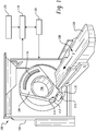
FIGURE 1 illustrates animaging system 100 such as a computed tomography scanner. Theimaging system 100 includes astationary gantry 102, which remains generally stationary during scanning, although it can be configured to tilt and/or otherwise be moved. Thesystem 100 also includes arotating gantry 104, which is rotatably supported by the - The rotating
gantry 104 supports aradiation source 110, such as an x-ray tube. In the illustrated embodiment, theradiation source 110 includes an eight degree (8°) anode (not visible) and emits radiation from a focal spot (not visible) thereon. The emitted radiation traverses theexamination region 106 and any object or subject dispose therein. The focal spot emits radiation while therotating gantry 104, and hence theradiation source 110 and the focal spot, rotate around the z-axis 108 during a helical or axial scan or are at a static position for a pilot or scout scan. - In the illustrated embodiment, the focal spot can translate along the z-axis physically, for example, by translating the
radiation source 110 along the z-axis, and/or electronically. In one non-limiting instance, the focal spot translates in coordination with motion of an object such as an organ like the heart disposed within theexamination region 106 or a flow of a contrast agent or the like through an object disposed within theexamination region 106. Such coordination can be in connection with fly-by scanning in which theradiation source 110 physically translates along the z-axis 108. Examples of such scanning are discussed at least in patent application serial no.PCT/US07/78130, filed September 11, 2007 , and entitled "Fly-By Scanning," and published asWO2008/042564 . - A
source collimator 112 translates in coordination with theradiation source 110 and collimates the emitted radiation in the z-axis direction to produce a generally conical shaped radiation beam that traverses theexamination region 106. Thecollimator 112 includes at least onecollimator blade 114 configured to translate in the z-axis direction, relative to theradiation source 110. The illustratedscanner 100 includesN collimator blades 114, wherein N is two (2). In other embodiments, N can be more or less than two (2). - In the illustrated embodiment, the
source collimator 112 is employed to produce a cone beam, which has a cone angle along the z-axis that defines the z-axis width or scan coverage. As described in greater detail below, in one instance thesource collimator 112 increases the effective maximum cone-beam angle in both directions along the z-axis. This may include symmetrically or asymmetrically increasing the cone beam angle in both directions along the z-axis about an imaginary axis that extends perpendicularly from the focal spot through a center region of theexamination region 106 through the z-axis 108. It is to be appreciated that by increasing the cone beam angle as such, the z-axis coverage can be expanded while maintaining the same radiation source power, relative to a configuration where the cone beam angle is not increased beyond the effective maximum cone-beam angle, which generally is defined by the angle of the anode (not visible) of theradiation source 110. - A
controller 115 controls thesource collimator 112 based on a scan protocol, including, but not limited to, a fly by scan or other scan protocol, and/or otherwise. - The rotating
gantry 104 also supports a radiationsensitive detector array 116, which is disposed about the rotatinggantry portion 104 and subtends an angular arc opposite theradiation source 110. Thedetector array 116 includes a multi-slice detector having a plurality of detector elements extending in the axial and transverse directions. Each detector element detects radiation emitted by theradiation source 110 that traverses theexamination region 106 for at least one hundred and eighty degrees (180°) plus a fan angle of data, and generates a corresponding output signal or projection data indicative of the detected radiation. A non-limiting example of a suitable detector includes a tile detector as are described inUS patent 6,510,195 B1 to Chappo et al., filed July 18, 2001 , and entitled "Solid State X-Radiation Detector Modules and Mosaics Thereof, and an Imaging Method and Apparatus Employing the Same". - A one or two dimensional anti-scatter grid may be employed in connection with the
detector array 116 to mitigate or reduce detection of scatter radiation. - The projection data generated by the
detector array 116 are conveyed to areconstructor 118, which reconstructs the projections and generates volumetric image data. The image data can be processed by an image processor to generate one or more images of the scanned region of interest or a subset thereof. - A
data corrector 120 can be used to correct the data for reconstruction. In one instance, this includes applying a correction that reduces the heel effect by providing a correction for increased attenuation and/or beam hardening. Such a correction may be used when the employed cone beam angle exceeds the effective maximum cone beam angle, as defined by the anode angle. As the heel effect varies along the z-axis, the correction may vary along the z-axis, with the largest correction generally being applied to the end ray(s) on the heel side of the cone beam. - An
operator console 122 facilitates user interaction with theimaging system 100. Software applications executed by theoperator console 122 allow the user to configure and/or control operation of theimaging system 100. For instance, the user can interact with theoperator console 122 to select a fly-by or other scan protocol, and initiate, pause and/or terminate a scan, etc. - A couch or
patient support 124 supports an object or subject such as a human or animal within theexamination region 106. Thesupport 124 can be movable, which enables an operator or the system to suitably position the object or subject within theexamination region 106 before, during and/or after scanning. - The
above system 100 can be employed for various applications. By way of non-limiting example, thesystem 100 is suited for whole organ scanning, such as scanning the entire heart or a substantial portion thereof in a single heart beat, if desired. Such a scan may be a fly-by or other scan performed with a radiation source having an eight degree (8°) or other angle anode, using full radiation source power for coverage between eight (8) to forty (40) centimeters (cm), such as 8 cm, 9 cm, 10 cm, 11 cm, 12 cm, etc. scans with minimal to substantially no motion artifacts and minimal to substantially no cone beam artifacts. With a fly-by scan, sufficient coverage can be obtained without sacrificing power and image quality. - As briefly discussed above, the illustrated
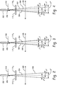
radiation source 110 can include an eight degree (8°) anode.FIGURE 2 illustrates such ananode 202 in connection withcollimator blades collimator blades axis 204, which extends perpendicularly from afocal spot 206 through the z-axis 108. With such a configuration, in one non-limiting example, thedetector array 116 includes one hundred and twenty eight (128) rows of detector pixels along the z-axis 108, where each pixel is about 0.625 mm. Of course, more or less rows and/or other size pixels can be used in other embodiments. - Generally, the anode angle defines an effective maximum cone angle of a
cone beam 208 that is symmetric about theaxis 204, as the heel effect attenuates and hardens beam rays emanating from thefocal spot 206 on the anode side of theaxis 204 when the cone angle is greater than the effective maximum cone angle. As the cone angle increases beyond the effective maximum cone angle, the intensity of the rays substantially falls off and the rays are substantially attenuated such that the intensity and energy of the rays generally are not effective for CT applications. Such data does not render diagnostic data while still irradiating the patient. For an eight (8) degree anode angle, this angle is about eight degrees (8°), or four degrees (4°) on each side of theaxis 204. - As shown in
FIGURE 2 , thecollimator blades 114 can be positioned to substantially or completely collimate rays emanating from thefocal spot 206 at an angle greater than the effective maximum cone angle. With theanode 202 having an eight degree (8°) anode angle, theradiation source 110 can be operated at full power, with local heating from anelectron beam 210 spread about theanode 202 as theanode 202 rotates and spread radially along theanode 202 slope. With this configuration, the effective focal spot size, as seen at thedetector array 116, is small enough so as to maintain a suitable resolution along the z-axis, while providing suitable z-axis coverage and maximizing radiation source power. - As shown in
FIGURE 3 , thecollimator blades system 100 can be symmetrically opened to allow for a larger angle cone beam. In this example, thecollimator blades FIGURE 2 , to about ten degrees (10°), with five degrees (5°) on each side of theaxis 204. Relative to the configuration shown inFIGURE 2 , a resultingbeam 302 has an expanded width along the z-axis, allowing for more rows of detector pixels, such as, for example, one hundred and sixty (160) rows of detector pixels, where each pixel is about 0.625 mm. - Note that the beam gets harder on the heel side and that a heel correction is applied to compensate for this hardening. As such, helical cone beam scans with extended z-axis coverage, for example, up to ten centimeters (10 cm), can be performed while maintaining radiation source power, without introducing significantly greater cone beam artifacts and/or decreasing resolution. Moreover, scan time and/or motion artifacts can be reduced. Similarly, more or less rows and/or other size pixels can be used in other embodiments. With the system of
FIGURE 2 , the coverage is smaller, and with a system with a larger anode angle so as to achieve 10 cm of coverage, tube power must reduced, which may reduce image quality. - As shown in
FIGURE 4 , thecollimator blades collimator blades FIGURE 2 , to twelve degrees (12°), with five degrees (5°) on the heel side of theaxis 204 and seven degrees (7°) on the other side of theaxis 204. Again, relative to the configuration shown inFIGURE 2 , a resultingbeam 402 has an expanded width along the z-axis, allowing for more rows of detector pixels, such as, for example, one hundred and ninety-two (192) rows of detector pixels, where each pixel is about 0.625 mm. - As such, helical cone beam scans with extended z-axis coverage, for example, up to twelve centimeters (12 cm), can be performed while maintaining radiation source power, without significantly increasing cone beam artifacts and/or decreasing resolution, and possibly reducing scan time and/or motion artifacts. Note that with this configuration, the extended cone beam provides fifty percent (50%) more coverage for the same radiation source power used in connection with the embodiment of
FIGURE 2 . Again, more or less rows and/or other size pixels can be used in other embodiments. In addition, with the system ofFIGURE 2 , the coverage is smaller, and with a system with a larger anode angle so as to achieve 12 cm of coverage, tube power must reduced, which may reduce image quality. - In another embodiment, only the
collimator blade 1141 on theanode 202 side is opened to increase the cone beam angel larger then the effective maximum cone beam angle as determined by the heel effect and anode angle. Thecollimator blade 1141 may be opened from one (1) to three (3) centimeters. Again, relative to the configuration shown inFIGURE 2 , the resulting beam has an expanded width along the z-axis. Furthermore, a beam hardening or heel correction is applied to compensate for beam hardening artifact. - The
above system 100 can be employed for various applications. By way of non-limiting example, thesystem 100 is suited for whole organ scanning, such as scanning the entire heart or a substantial portion thereof in a single heart beat, if desired. Such a scan may be a fly-by or other scan performed with a radiation source having an eight degree (8°) or other angle anode, using full radiation source power for coverage between eight centimeters (8 cm) to forty centimeters (40 cm), such as 8 cm, 9 cm, 10 cm, 11 cm, 12 cm, etc. centimeters scans with minimal to substantially no motion artifacts and minimal to substantially no cone beam artifacts. With a fly-by scan, sufficient coverage can be obtained without sacrificing power and image quality. - They expanded coverage discussed above can be used with a fly-by scan. In such an instance, motion can be reduced relative to a configuration in which the cone beam angle is at most equal to the effective maximum cone angle as determined by the anode angle.
- The above examples are provided for explanatory purposes and are not limiting. In other embodiments, radiation sources with larger or smaller anode angles and/or cone beams with larger or smaller symmetric or asymmetric cone angles are contemplated. For example, suitable anode angles range from seven (7) to twelve (12) degree angles correspond to suitable extended cone beam angles up to ten (10) to twenty (20) degree angles, etc.
- The
imaging system 100 can be used for various applications, including helical and/or axial scans. Generally, cone beam artifacts are smaller (e.g., less than twenty percent (20%)) for helical scans relative to axial scans, and for some helical scans, the cone beam artifacts are minimal. This is shown in connection withFIGURE 5 , which shows acone beam 502 at afirst position 504 and asecond position 506, which is one hundred and eighty (180) degrees offset from thefirst position 504. The anode angle is eight degrees (8°) and thecollimator blades 114 are positioned so that the cone beam has a twelve degree (12°) angle, as shown in connection withFIGURE 4 above. The pitch factor is one and three quarters (1.75). With these parameters, adistance 508 between aray 510 extending perpendicularly from a focal spot through the z-axis 108 at thepositions relative angle 512 between thebeam 502 at the twopositions - Slice sensitivity is also generally more uniform for helical scans relative to axial scans. That is, for a given voxel in a helical reconstruction, the z-axis response will vary from about sixty percent (60%) of a nominal size to about one hundred and eighty-eight percent (188%) of the nominal size when the
collimator blades 114 are positioned for a cone beam with an extended cone angle of twelve degrees (12°), as illustrated inFIGURE 4 . By way of example, with such a configuration, the size of a given voxel at the center of the cone will be about half a millimeter (0.5 mm), whereas the size of the voxel on the heel side of theaxis 204 will be about three tenths of a millimeter (0.3 mm) and the size of the voxel on the other side of the axis will be about nine tenths of a millimeter (0.9 mm). The nominal size of the voxel will be the composite of the foregoing responses. As such, all voxels may have about the same nominal slice width sensitivity. - As noted herein, in one embodiment the
collimator blades 114 can be positioned to increase z-axis coverage without reducing or sacrificing radiation source power or resolution or significantly increasing cone beam artifacts, noting that a heel effect correction may be performed on the data to correct for both increased attenuation and beam hardening, relative to an embodiment in which thecollimator blades 114 are positioned based on the effective maximum cone angle defined by the anode angle, which assumes a maximum heel angle of 4 degrees for an 8 degree anode. A non-limiting suitable heel affect correction can be found in patent applicationWO/2005/059592 ,PCT/IB2002/052673, filed on December 6, 2004 - Example operation of the
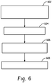
system 100 is discussed in connection withFIGURE 6 . It is to be appreciated that the order of the following acts is not limiting and may otherwise occur. In addition, more or less, including similar or different acts may be employed in other embodiments. - At 602, a cone beam having an extended cone angle along the z-axis and thus an extended z-axis scan coverage is produced. As discussed above, this may include symmetrically or asymmetrically opening the
collimator blades 114 about thecentral ray axis 204 so as to produce a cone beam with a cone angle that is larger than the effective maximum cone angle determined by the anode angle. - At 604, a scan is performed with the cone beam. Such a scan may be a helical scan such as a fly by or other scan, an axial scan, and/or another scan. In addition, the scan can involve scanning an entire organ, such as a static or moving organ, without having to move or substantially move the
radiation source 110 and/or the object or subject being scanned. - At 606, while performing the scan, the radiation source power is maintained at a power level such as full power as if the cone beam angle is not extended, but equal to the effective maximum cone beam angle. In one instance, this may be defined by 2(α-4).
- At 608, an optional heel effect correction is applied. Such a correction can be applied to the raw data, the reconstructed volumetric image data, and/or one or more images generated as part of the reconstructed volumetric image data.
- The above may be implemented by way of computer readable instructions, which when executed by a computer processor(s), cause the processor(s) to carry out the foregoing. In such a case, the instructions are stored in a computer readable storage medium associated with or otherwise accessible to a relevant computer, such as a dedicated workstation, a home computer, a distributed computing system, the console, and/or other computer. The acts need not be performed concurrently with data acquisition.
- The above may be used in various applications including applications where it may be desirable to achieve relatively large coverage in a relatively short period of time without moving the patient support such as for cardiac, trauma, perfusion and/or other applications.
Claims (11)
- An imaging system, wherein the imaging system is a medical computed tomography scanner comprising:a radiation source (110), including an anode (202), that is adapted to rotate around an examination region (106) about a longitudinal axis (108) and adapted to emit radiation from a focal spot (206) on the anode (202);said anode having an anode angle characterised by a source collimator (112) that is adapted to collimate the emitted radiation to produce a conically shaped radiation beam that traverses the examination region, wherein the conically shaped radiation beam has an extended cone angle along the longitudinal axis that is greater than an effective maximum cone angle defined by a limitation of the cone angle by the heel effect, wherein, as the cone angle increases beyond the effective maximum cone angle, the intensity of rays falls off and the rays are attenuated due to the heel effect, which attenuates and hardens the rays emanating from the focal spot (206) on the anode side of an axis (204, 510) which extends perpendicularly from the focal spot through the longitudinal axis, wherein the collimator is positioned to collimate the emitted radiation emanating from the focal spot such that said extended cone angle on the heel side is greater than the anode angle;a detector array (116) that is adapted to detect radiation that traverses the examination region and generate signals indicative thereof; anda reconstructor (118) that is adapted to reconstruct the signals to generate volumetric image data indicative of the examination region; whereinthe medical computed tomography scanner further comprises a data corrector (120) that is adapted to correct the signal for the heel effect, wherein the data corrector is adapted to correct for both increased attenuation and beam hardening.
- The system of claim 1, wherein the extended cone angle is symmetrically extended in both directions along the longitudinal axis.
- The system of claim 1, wherein the extended cone angle is asymmetrically extended in both directions along the longitudinal axis.
- The system of any of claims 1 to 3, wherein the radiation source (110) is adapted to translate physically along the longitudinal axis (108) during a fly-by scan.
- The system of any of claims 1 to 4, wherein the effective maximum cone angle is about eight degrees and the extended cone angle is about ten to about twelve degrees.
- The system of claim 5, wherein the extended cone angle is extended in the direction of the anode by about one degree and in the direction of the cathode by about one to about three degrees.
- The system of any of claims 1 to 6, wherein the system is adapted to perform a helical scan and at least two voxels have the same nominal slice width sensitivity.
- A method, wherein the method is a method for acquiring projection data to be used for reconstructing volumetric medical computed tomography image data indicative of an examination region, the method characterised by comprising:collimating a radiation beam emitted from a focal spot (206) on an anode (202), said anode having an anode angle, of a radiation source (110) of an imaging system (100) to produce a conically shaped radiation beam having an extended cone angle along a longitudinal axis that is greater than an effective maximum cone angle, wherein the effective maximum cone angle is defined by a limitation of the cone angle by the heel effect, wherein, as the cone angle increases beyond the effective maximum cone angle, the intensity of rays falls off and the rays are attenuated due to the heel effect, which attenuates and hardens the rays emanating from the focal spot (206) on the anode side of an axis (204) which extends perpendicularly from the focal spot through the longitudinal axis, wherein the collimator is positioned to collimate the emitted radiation emanating from the focal spot such that said extended cone angle on the heel side is greater than the anode angle; andacquiring projection data indicative of the radiation that traverses an examination region (106) and illuminates a detector array (116);wherein a data corrector corrects the projection data for the heel effect, wherein the data corrector is adapted to correct for both increased attenuation and beam hardening.
- The method of claim 8, , further including symmetrically extending the cone angle in both directions along the longitudinal axis.
- The method of claim 8, further including asymmetrically extending the cone angle in both directions along the longitudinal axis.
- A computer readable medium characterized in that the computer readable medium is encoded with computer readable instructions, which, when executed by a computer processor(s), cause the processor(s) to:provide a control signal to position collimator blades (114) of a collimator (112) to collimate a radiation beam emitted from a focal spot (206) on an anode (202) of a radiation source (110) of a medical computed tomography scanner (100), said anode having an anode angle, to selectively produce a conically shaped radiation beam alternatively having a symmetrically or asymmetrically extended cone angle along a longitudinal axis that is greater than an effective maximum cone angle defined by a limitation of the cone angle by the heel effect, wherein, as the cone angle increases beyond the effective maximum cone angle, the intensity of rays falls off and the rays are attenuated due to the heel effect, which attenuates and hardens the rays emanating from the focal spot (206) on the anode side of an axis (204) which extends perpendicularly from the focal spot through the longitudinal axis, wherein the collimator is positioned to collimate the emitted radiation emanating from the focal spot such that said extended cone angle on the heel side is greater than the anode angle, wherein projection data, which are indicative of the radiation that traverses an examination region and illuminates a detector array, are corrected for the heel effect, wherein the projection data are corrected for both increased attenuation and beam hardening.
Applications Claiming Priority (2)
| Application Number | Priority Date | Filing Date | Title |
|---|---|---|---|
| US11229108P | 2008-11-07 | 2008-11-07 | |
| PCT/IB2009/054790 WO2010052614A1 (en) | 2008-11-07 | 2009-10-28 | Cone beam z-axis coverage |
Publications (2)
| Publication Number | Publication Date |
|---|---|
| EP2352432A1 EP2352432A1 (en) | 2011-08-10 |
| EP2352432B1 true EP2352432B1 (en) | 2017-02-22 |
Family
ID=41571371
Family Applications (1)
| Application Number | Title | Priority Date | Filing Date |
|---|---|---|---|
| EP09760600.8A Active EP2352432B1 (en) | 2008-11-07 | 2009-10-28 | Cone beam z-axis coverage |
Country Status (4)
| Country | Link |
|---|---|
| US (1) | US8467494B2 (en) |
| EP (1) | EP2352432B1 (en) |
| CN (1) | CN102202578B (en) |
| WO (1) | WO2010052614A1 (en) |
Families Citing this family (6)
| Publication number | Priority date | Publication date | Assignee | Title |
|---|---|---|---|---|
| US8897413B2 (en) * | 2008-05-21 | 2014-11-25 | Koninklijke Philips N.V. | Dynamic adjustable source collimation during fly-by scanning |
| US8566619B2 (en) * | 2009-12-30 | 2013-10-22 | International Business Machines Corporation | Cooling appliance rating aware data placement |
| RU2014105575A (en) * | 2011-07-15 | 2015-08-27 | Конинклейке Филипс Н.В. | DYNAMIC COLLIMATION |
| JP6615439B2 (en) * | 2014-08-01 | 2019-12-04 | キヤノンメディカルシステムズ株式会社 | X-ray CT system |
| EP3632325A1 (en) * | 2018-10-04 | 2020-04-08 | Koninklijke Philips N.V. | System for providing a spectral image |
| CN110368018A (en) * | 2019-08-22 | 2019-10-25 | 南京安科医疗科技有限公司 | A kind of CT system scanning dynamic regulating method |
Citations (2)
| Publication number | Priority date | Publication date | Assignee | Title |
|---|---|---|---|---|
| US20050123100A1 (en) * | 2003-12-05 | 2005-06-09 | Jiang Hsieh | Method and system for target angle heel effect compensation |
| WO2005059592A1 (en) * | 2003-12-16 | 2005-06-30 | Philips Intellectual Property & Standards Gmbh | Correction of artifacts caused by the heel effect |
Family Cites Families (7)
| Publication number | Priority date | Publication date | Assignee | Title |
|---|---|---|---|---|
| US6330299B1 (en) * | 2000-06-10 | 2001-12-11 | Ge Medical Systems Global Technology Company, Llc | System and method for determining dose area product in an X-ray imaging system |
| US6510195B1 (en) * | 2001-07-18 | 2003-01-21 | Koninklijke Philips Electronics, N.V. | Solid state x-radiation detector modules and mosaics thereof, and an imaging method and apparatus employing the same |
| JP4310269B2 (en) * | 2002-05-06 | 2009-08-05 | コーニンクレッカ フィリップス エレクトロニクス エヌ ヴィ | High resolution CT scanner |
| CN100492411C (en) * | 2003-02-20 | 2009-05-27 | 皇家飞利浦电子股份有限公司 | Asymmetric cone beam |
| WO2005092195A1 (en) * | 2004-03-29 | 2005-10-06 | National Institute Of Radiological Sciences | Heel effect correction filter, x-ray irradiator, x-ray ct apparatus, and x-ray ct imaging method |
| GB2422759B (en) | 2004-08-05 | 2008-07-16 | Elekta Ab | Rotatable X-ray scan apparatus with cone beam offset |
| EP2073710B1 (en) | 2006-09-29 | 2016-05-04 | Koninklijke Philips N.V. | Fly-by scanning for computed tomography |
-
2009
- 2009-10-28 CN CN200980144121.0A patent/CN102202578B/en active Active
- 2009-10-28 US US13/127,241 patent/US8467494B2/en active Active
- 2009-10-28 WO PCT/IB2009/054790 patent/WO2010052614A1/en active Application Filing
- 2009-10-28 EP EP09760600.8A patent/EP2352432B1/en active Active
Patent Citations (2)
| Publication number | Priority date | Publication date | Assignee | Title |
|---|---|---|---|---|
| US20050123100A1 (en) * | 2003-12-05 | 2005-06-09 | Jiang Hsieh | Method and system for target angle heel effect compensation |
| WO2005059592A1 (en) * | 2003-12-16 | 2005-06-30 | Philips Intellectual Property & Standards Gmbh | Correction of artifacts caused by the heel effect |
Non-Patent Citations (1)
| Title |
|---|
| MALTZ J S ET AL: "Algorithm for X-ray Scatter, Beam-Hardening, and Beam Profile Correction in Diagnostic (Kilovoltage) and Treatment (Megavoltage) Cone Beam CT", IEEE TRANSACTIONS ON MEDICAL IMAGING, IEEE SERVICE CENTER, PISCATAWAY, NJ, US, vol. 27, no. 12, 1 December 2008 (2008-12-01), pages 1791 - 1810, XP011232055, ISSN: 0278-0062, DOI: 10.1109/TMI.2008.928922 * |
Also Published As
| Publication number | Publication date |
|---|---|
| EP2352432A1 (en) | 2011-08-10 |
| WO2010052614A1 (en) | 2010-05-14 |
| US8467494B2 (en) | 2013-06-18 |
| CN102202578A (en) | 2011-09-28 |
| US20110211664A1 (en) | 2011-09-01 |
| CN102202578B (en) | 2014-08-06 |
Similar Documents
| Publication | Publication Date | Title |
|---|---|---|
| US7515678B2 (en) | Method and system for performing CT image reconstruction with motion artifact correction | |
| US6373920B1 (en) | Method and apparatus for acquiring CT perfusion images | |
| EP2234541B1 (en) | Stereo tube attenuation filter | |
| US8031828B1 (en) | Method and apparatus for computed tomography | |
| JP6014323B2 (en) | X-ray system | |
| US6421411B1 (en) | Methods and apparatus for helical image artifact reduction | |
| US7532702B2 (en) | Method and system for performing CT image reconstruction with motion artifact correction | |
| US6421412B1 (en) | Dual cardiac CT scanner | |
| JP5905694B2 (en) | A computed tomography scanner with a dynamic collimator for cardiac CT imaging with wide coverage and low dose | |
| US20080279328A1 (en) | Systems and Methods Using X-Ray Tube Spectra For Computed Tomography Applications | |
| US6385278B1 (en) | Method and apparatus for region of interest multislice CT scan | |
| US7782999B2 (en) | Systems and methods for scanning and data acquisition in computed tomography (CT) applications | |
| US6061419A (en) | Methods and apparatus for noise compensation in an imaging system | |
| US20100308229A1 (en) | Movable wedge for improved image quality in 3d x-ray imaging | |
| EP2352432B1 (en) | Cone beam z-axis coverage | |
| US20060193430A1 (en) | Computerized tomographic imaging system | |
| US9042514B2 (en) | Dose reduction via dynamic collimation adjustment for targeted field of view and/or digital tilt CT | |
| JP2003502130A (en) | Local CT image reconstruction with limited X-ray exposure | |
| IL137107A (en) | Methods and apparatus for noise compensation in imaging systems | |
| JP2008012206A (en) | X-ray tomographic apparatus | |
| Grasruck et al. | Evaluation of image quality and dose on a flat-panel CT-scanner | |
| WO2008075267A2 (en) | Device and method for imaging an object | |
| US20060243914A1 (en) | Attenuation map generation from pet scans |
Legal Events
| Date | Code | Title | Description |
|---|---|---|---|
| PUAI | Public reference made under article 153(3) epc to a published international application that has entered the european phase |
Free format text: ORIGINAL CODE: 0009012 |
|
| 17P | Request for examination filed |
Effective date: 20110607 |
|
| AK | Designated contracting states |
Kind code of ref document: A1 Designated state(s): AT BE BG CH CY CZ DE DK EE ES FI FR GB GR HR HU IE IS IT LI LT LU LV MC MK MT NL NO PL PT RO SE SI SK SM TR |
|
| DAX | Request for extension of the european patent (deleted) | ||
| 17Q | First examination report despatched |
Effective date: 20120321 |
|
| RAP1 | Party data changed (applicant data changed or rights of an application transferred) |
Owner name: KONINKLIJKE PHILIPS N.V. |
|
| GRAJ | Information related to disapproval of communication of intention to grant by the applicant or resumption of examination proceedings by the epo deleted |
Free format text: ORIGINAL CODE: EPIDOSDIGR1 |
|
| GRAP | Despatch of communication of intention to grant a patent |
Free format text: ORIGINAL CODE: EPIDOSNIGR1 |
|
| GRAP | Despatch of communication of intention to grant a patent |
Free format text: ORIGINAL CODE: EPIDOSNIGR1 |
|
| INTG | Intention to grant announced |
Effective date: 20160909 |
|
| GRAS | Grant fee paid |
Free format text: ORIGINAL CODE: EPIDOSNIGR3 |
|
| GRAA | (expected) grant |
Free format text: ORIGINAL CODE: 0009210 |
|
| AK | Designated contracting states |
Kind code of ref document: B1 Designated state(s): AT BE BG CH CY CZ DE DK EE ES FI FR GB GR HR HU IE IS IT LI LT LU LV MC MK MT NL NO PL PT RO SE SI SK SM TR |
|
| REG | Reference to a national code |
Ref country code: GB Ref legal event code: FG4D |
|
| REG | Reference to a national code |
Ref country code: CH Ref legal event code: EP |
|
| REG | Reference to a national code |
Ref country code: AT Ref legal event code: REF Ref document number: 868652 Country of ref document: AT Kind code of ref document: T Effective date: 20170315 |
|
| REG | Reference to a national code |
Ref country code: IE Ref legal event code: FG4D |
|
| REG | Reference to a national code |
Ref country code: DE Ref legal event code: R096 Ref document number: 602009044335 Country of ref document: DE |
|
| REG | Reference to a national code |
Ref country code: DE Ref legal event code: R084 Ref document number: 602009044335 Country of ref document: DE |
|
| REG | Reference to a national code |
Ref country code: LT Ref legal event code: MG4D |
|
| REG | Reference to a national code |
Ref country code: NL Ref legal event code: MP Effective date: 20170222 |
|
| REG | Reference to a national code |
Ref country code: AT Ref legal event code: MK05 Ref document number: 868652 Country of ref document: AT Kind code of ref document: T Effective date: 20170222 |
|
| PG25 | Lapsed in a contracting state [announced via postgrant information from national office to epo] |
Ref country code: HR Free format text: LAPSE BECAUSE OF FAILURE TO SUBMIT A TRANSLATION OF THE DESCRIPTION OR TO PAY THE FEE WITHIN THE PRESCRIBED TIME-LIMIT Effective date: 20170222 Ref country code: LT Free format text: LAPSE BECAUSE OF FAILURE TO SUBMIT A TRANSLATION OF THE DESCRIPTION OR TO PAY THE FEE WITHIN THE PRESCRIBED TIME-LIMIT Effective date: 20170222 Ref country code: FI Free format text: LAPSE BECAUSE OF FAILURE TO SUBMIT A TRANSLATION OF THE DESCRIPTION OR TO PAY THE FEE WITHIN THE PRESCRIBED TIME-LIMIT Effective date: 20170222 Ref country code: NO Free format text: LAPSE BECAUSE OF FAILURE TO SUBMIT A TRANSLATION OF THE DESCRIPTION OR TO PAY THE FEE WITHIN THE PRESCRIBED TIME-LIMIT Effective date: 20170522 Ref country code: GR Free format text: LAPSE BECAUSE OF FAILURE TO SUBMIT A TRANSLATION OF THE DESCRIPTION OR TO PAY THE FEE WITHIN THE PRESCRIBED TIME-LIMIT Effective date: 20170523 |
|
| PG25 | Lapsed in a contracting state [announced via postgrant information from national office to epo] |
Ref country code: AT Free format text: LAPSE BECAUSE OF FAILURE TO SUBMIT A TRANSLATION OF THE DESCRIPTION OR TO PAY THE FEE WITHIN THE PRESCRIBED TIME-LIMIT Effective date: 20170222 Ref country code: BG Free format text: LAPSE BECAUSE OF FAILURE TO SUBMIT A TRANSLATION OF THE DESCRIPTION OR TO PAY THE FEE WITHIN THE PRESCRIBED TIME-LIMIT Effective date: 20170522 Ref country code: SE Free format text: LAPSE BECAUSE OF FAILURE TO SUBMIT A TRANSLATION OF THE DESCRIPTION OR TO PAY THE FEE WITHIN THE PRESCRIBED TIME-LIMIT Effective date: 20170222 Ref country code: NL Free format text: LAPSE BECAUSE OF FAILURE TO SUBMIT A TRANSLATION OF THE DESCRIPTION OR TO PAY THE FEE WITHIN THE PRESCRIBED TIME-LIMIT Effective date: 20170222 Ref country code: LV Free format text: LAPSE BECAUSE OF FAILURE TO SUBMIT A TRANSLATION OF THE DESCRIPTION OR TO PAY THE FEE WITHIN THE PRESCRIBED TIME-LIMIT Effective date: 20170222 Ref country code: PT Free format text: LAPSE BECAUSE OF FAILURE TO SUBMIT A TRANSLATION OF THE DESCRIPTION OR TO PAY THE FEE WITHIN THE PRESCRIBED TIME-LIMIT Effective date: 20170622 Ref country code: ES Free format text: LAPSE BECAUSE OF FAILURE TO SUBMIT A TRANSLATION OF THE DESCRIPTION OR TO PAY THE FEE WITHIN THE PRESCRIBED TIME-LIMIT Effective date: 20170222 |
|
| PG25 | Lapsed in a contracting state [announced via postgrant information from national office to epo] |
Ref country code: EE Free format text: LAPSE BECAUSE OF FAILURE TO SUBMIT A TRANSLATION OF THE DESCRIPTION OR TO PAY THE FEE WITHIN THE PRESCRIBED TIME-LIMIT Effective date: 20170222 Ref country code: IT Free format text: LAPSE BECAUSE OF FAILURE TO SUBMIT A TRANSLATION OF THE DESCRIPTION OR TO PAY THE FEE WITHIN THE PRESCRIBED TIME-LIMIT Effective date: 20170222 Ref country code: RO Free format text: LAPSE BECAUSE OF FAILURE TO SUBMIT A TRANSLATION OF THE DESCRIPTION OR TO PAY THE FEE WITHIN THE PRESCRIBED TIME-LIMIT Effective date: 20170222 Ref country code: CZ Free format text: LAPSE BECAUSE OF FAILURE TO SUBMIT A TRANSLATION OF THE DESCRIPTION OR TO PAY THE FEE WITHIN THE PRESCRIBED TIME-LIMIT Effective date: 20170222 Ref country code: SK Free format text: LAPSE BECAUSE OF FAILURE TO SUBMIT A TRANSLATION OF THE DESCRIPTION OR TO PAY THE FEE WITHIN THE PRESCRIBED TIME-LIMIT Effective date: 20170222 |
|
| REG | Reference to a national code |
Ref country code: FR Ref legal event code: PLFP Year of fee payment: 9 |
|
| REG | Reference to a national code |
Ref country code: DE Ref legal event code: R097 Ref document number: 602009044335 Country of ref document: DE |
|
| PG25 | Lapsed in a contracting state [announced via postgrant information from national office to epo] |
Ref country code: PL Free format text: LAPSE BECAUSE OF FAILURE TO SUBMIT A TRANSLATION OF THE DESCRIPTION OR TO PAY THE FEE WITHIN THE PRESCRIBED TIME-LIMIT Effective date: 20170222 Ref country code: SM Free format text: LAPSE BECAUSE OF FAILURE TO SUBMIT A TRANSLATION OF THE DESCRIPTION OR TO PAY THE FEE WITHIN THE PRESCRIBED TIME-LIMIT Effective date: 20170222 Ref country code: DK Free format text: LAPSE BECAUSE OF FAILURE TO SUBMIT A TRANSLATION OF THE DESCRIPTION OR TO PAY THE FEE WITHIN THE PRESCRIBED TIME-LIMIT Effective date: 20170222 |
|
| PLBE | No opposition filed within time limit |
Free format text: ORIGINAL CODE: 0009261 |
|
| STAA | Information on the status of an ep patent application or granted ep patent |
Free format text: STATUS: NO OPPOSITION FILED WITHIN TIME LIMIT |
|
| 26N | No opposition filed |
Effective date: 20171123 |
|
| PG25 | Lapsed in a contracting state [announced via postgrant information from national office to epo] |
Ref country code: SI Free format text: LAPSE BECAUSE OF FAILURE TO SUBMIT A TRANSLATION OF THE DESCRIPTION OR TO PAY THE FEE WITHIN THE PRESCRIBED TIME-LIMIT Effective date: 20170222 |
|
| PG25 | Lapsed in a contracting state [announced via postgrant information from national office to epo] |
Ref country code: MC Free format text: LAPSE BECAUSE OF FAILURE TO SUBMIT A TRANSLATION OF THE DESCRIPTION OR TO PAY THE FEE WITHIN THE PRESCRIBED TIME-LIMIT Effective date: 20170222 |
|
| REG | Reference to a national code |
Ref country code: CH Ref legal event code: PL |
|
| GBPC | Gb: european patent ceased through non-payment of renewal fee |
Effective date: 20171028 |
|
| REG | Reference to a national code |
Ref country code: IE Ref legal event code: MM4A |
|
| PG25 | Lapsed in a contracting state [announced via postgrant information from national office to epo] |
Ref country code: CH Free format text: LAPSE BECAUSE OF NON-PAYMENT OF DUE FEES Effective date: 20171031 Ref country code: LI Free format text: LAPSE BECAUSE OF NON-PAYMENT OF DUE FEES Effective date: 20171031 Ref country code: LU Free format text: LAPSE BECAUSE OF NON-PAYMENT OF DUE FEES Effective date: 20171028 Ref country code: GB Free format text: LAPSE BECAUSE OF NON-PAYMENT OF DUE FEES Effective date: 20171028 |
|
| REG | Reference to a national code |
Ref country code: BE Ref legal event code: MM Effective date: 20171031 |
|
| PG25 | Lapsed in a contracting state [announced via postgrant information from national office to epo] |
Ref country code: BE Free format text: LAPSE BECAUSE OF NON-PAYMENT OF DUE FEES Effective date: 20171031 |
|
| PG25 | Lapsed in a contracting state [announced via postgrant information from national office to epo] |
Ref country code: MT Free format text: LAPSE BECAUSE OF NON-PAYMENT OF DUE FEES Effective date: 20171028 |
|
| REG | Reference to a national code |
Ref country code: FR Ref legal event code: PLFP Year of fee payment: 10 |
|
| PG25 | Lapsed in a contracting state [announced via postgrant information from national office to epo] |
Ref country code: IE Free format text: LAPSE BECAUSE OF NON-PAYMENT OF DUE FEES Effective date: 20171028 |
|
| PG25 | Lapsed in a contracting state [announced via postgrant information from national office to epo] |
Ref country code: HU Free format text: LAPSE BECAUSE OF FAILURE TO SUBMIT A TRANSLATION OF THE DESCRIPTION OR TO PAY THE FEE WITHIN THE PRESCRIBED TIME-LIMIT; INVALID AB INITIO Effective date: 20091028 |
|
| PG25 | Lapsed in a contracting state [announced via postgrant information from national office to epo] |
Ref country code: CY Free format text: LAPSE BECAUSE OF NON-PAYMENT OF DUE FEES Effective date: 20170222 |
|
| PG25 | Lapsed in a contracting state [announced via postgrant information from national office to epo] |
Ref country code: MK Free format text: LAPSE BECAUSE OF FAILURE TO SUBMIT A TRANSLATION OF THE DESCRIPTION OR TO PAY THE FEE WITHIN THE PRESCRIBED TIME-LIMIT Effective date: 20170222 |
|
| PG25 | Lapsed in a contracting state [announced via postgrant information from national office to epo] |
Ref country code: TR Free format text: LAPSE BECAUSE OF FAILURE TO SUBMIT A TRANSLATION OF THE DESCRIPTION OR TO PAY THE FEE WITHIN THE PRESCRIBED TIME-LIMIT Effective date: 20170222 |
|
| PG25 | Lapsed in a contracting state [announced via postgrant information from national office to epo] |
Ref country code: IS Free format text: LAPSE BECAUSE OF FAILURE TO SUBMIT A TRANSLATION OF THE DESCRIPTION OR TO PAY THE FEE WITHIN THE PRESCRIBED TIME-LIMIT Effective date: 20170622 |
|
| PGFP | Annual fee paid to national office [announced via postgrant information from national office to epo] |
Ref country code: FR Payment date: 20231026 Year of fee payment: 15 Ref country code: DE Payment date: 20231027 Year of fee payment: 15 |