EP2352218A2 - Spannungsausgleichsschaltkreis für eine stromspeichervorrichtung - Google Patents
Spannungsausgleichsschaltkreis für eine stromspeichervorrichtung Download PDFInfo
- Publication number
- EP2352218A2 EP2352218A2 EP20090836276 EP09836276A EP2352218A2 EP 2352218 A2 EP2352218 A2 EP 2352218A2 EP 20090836276 EP20090836276 EP 20090836276 EP 09836276 A EP09836276 A EP 09836276A EP 2352218 A2 EP2352218 A2 EP 2352218A2
- Authority
- EP
- European Patent Office
- Prior art keywords
- voltage equalization
- voltage
- cell
- electric energy
- energy storage
- Prior art date
- Legal status (The legal status is an assumption and is not a legal conclusion. Google has not performed a legal analysis and makes no representation as to the accuracy of the status listed.)
- Withdrawn
Links
Images


Classifications
-
- H—ELECTRICITY
- H02—GENERATION; CONVERSION OR DISTRIBUTION OF ELECTRIC POWER
- H02J—ELECTRIC POWER NETWORKS; CIRCUIT ARRANGEMENTS OR SYSTEMS FOR SUPPLYING OR DISTRIBUTING ELECTRIC POWER; SYSTEMS FOR STORING ELECTRIC ENERGY
- H02J7/00—Circuit arrangements for charging or discharging batteries or for supplying loads from batteries
- H02J7/50—Circuit arrangements for charging or discharging batteries or for supplying loads from batteries acting upon multiple batteries simultaneously or sequentially
- H02J7/52—Circuit arrangements for charging or discharging batteries or for supplying loads from batteries acting upon multiple batteries simultaneously or sequentially for charge balancing, e.g. equalisation of charge between batteries
- H02J7/56—Active balancing, e.g. using capacitor-based, inductor-based or DC-DC converters
-
- H—ELECTRICITY
- H02—GENERATION; CONVERSION OR DISTRIBUTION OF ELECTRIC POWER
- H02J—ELECTRIC POWER NETWORKS; CIRCUIT ARRANGEMENTS OR SYSTEMS FOR SUPPLYING OR DISTRIBUTING ELECTRIC POWER; SYSTEMS FOR STORING ELECTRIC ENERGY
- H02J7/00—Circuit arrangements for charging or discharging batteries or for supplying loads from batteries
- H02J7/50—Circuit arrangements for charging or discharging batteries or for supplying loads from batteries acting upon multiple batteries simultaneously or sequentially
- H02J7/52—Circuit arrangements for charging or discharging batteries or for supplying loads from batteries acting upon multiple batteries simultaneously or sequentially for charge balancing, e.g. equalisation of charge between batteries
- H02J7/54—Passive balancing, e.g. using resistors or parallel MOSFETs
-
- G—PHYSICS
- G01—MEASURING; TESTING
- G01R—MEASURING ELECTRIC VARIABLES; MEASURING MAGNETIC VARIABLES
- G01R19/00—Arrangements for measuring currents or voltages or for indicating presence or sign thereof
- G01R19/165—Indicating that current or voltage is either above or below a predetermined value or within or outside a predetermined range of values
- G01R19/16533—Indicating that current or voltage is either above or below a predetermined value or within or outside a predetermined range of values characterised by the application
- G01R19/16538—Indicating that current or voltage is either above or below a predetermined value or within or outside a predetermined range of values characterised by the application in AC or DC supplies
- G01R19/16542—Indicating that current or voltage is either above or below a predetermined value or within or outside a predetermined range of values characterised by the application in AC or DC supplies for batteries
-
- G—PHYSICS
- G01—MEASURING; TESTING
- G01R—MEASURING ELECTRIC VARIABLES; MEASURING MAGNETIC VARIABLES
- G01R31/00—Arrangements for testing electric properties; Arrangements for locating electric faults; Arrangements for electrical testing characterised by what is being tested not provided for elsewhere
- G01R31/36—Arrangements for testing, measuring or monitoring the electrical condition of accumulators or electric batteries, e.g. capacity or state of charge [SoC]
- G01R31/382—Arrangements for monitoring battery or accumulator variables, e.g. SoC
- G01R31/3835—Arrangements for monitoring battery or accumulator variables, e.g. SoC involving only voltage measurements
-
- H—ELECTRICITY
- H02—GENERATION; CONVERSION OR DISTRIBUTION OF ELECTRIC POWER
- H02J—ELECTRIC POWER NETWORKS; CIRCUIT ARRANGEMENTS OR SYSTEMS FOR SUPPLYING OR DISTRIBUTING ELECTRIC POWER; SYSTEMS FOR STORING ELECTRIC ENERGY
- H02J7/00—Circuit arrangements for charging or discharging batteries or for supplying loads from batteries
- H02J7/34—Parallel operation in networks using both storage and other DC sources, e.g. providing buffering
- H02J7/345—Parallel operation in networks using both storage and other DC sources, e.g. providing buffering using capacitors as storage or buffering devices
-
- H—ELECTRICITY
- H02—GENERATION; CONVERSION OR DISTRIBUTION OF ELECTRIC POWER
- H02J—ELECTRIC POWER NETWORKS; CIRCUIT ARRANGEMENTS OR SYSTEMS FOR SUPPLYING OR DISTRIBUTING ELECTRIC POWER; SYSTEMS FOR STORING ELECTRIC ENERGY
- H02J7/00—Circuit arrangements for charging or discharging batteries or for supplying loads from batteries
- H02J7/60—Circuit arrangements for charging or discharging batteries or for supplying loads from batteries including safety or protection arrangements
-
- H—ELECTRICITY
- H01—ELECTRIC ELEMENTS
- H01M—PROCESSES OR MEANS, e.g. BATTERIES, FOR THE DIRECT CONVERSION OF CHEMICAL ENERGY INTO ELECTRICAL ENERGY
- H01M10/00—Secondary cells; Manufacture thereof
- H01M10/42—Methods or arrangements for servicing or maintenance of secondary cells or secondary half-cells
- H01M10/425—Structural combination with electronic components, e.g. electronic circuits integrated to the outside of the casing
- H01M2010/4271—Battery management systems including electronic circuits, e.g. control of current or voltage to keep battery in healthy state, cell balancing
-
- H—ELECTRICITY
- H02—GENERATION; CONVERSION OR DISTRIBUTION OF ELECTRIC POWER
- H02J—ELECTRIC POWER NETWORKS; CIRCUIT ARRANGEMENTS OR SYSTEMS FOR SUPPLYING OR DISTRIBUTING ELECTRIC POWER; SYSTEMS FOR STORING ELECTRIC ENERGY
- H02J2207/00—Details of circuit arrangements for charging or discharging batteries or supplying loads from batteries
- H02J2207/50—Charging of capacitors, supercapacitors, ultra-capacitors or double layer capacitors
Definitions
- the present invention relates to a voltage equalization apparatus of an electrical energy storage apparatus, and more particularly, to a voltage equalization apparatus capable of rapidly performing voltage equalization between electrical energy storage cells in the electric energy storage device configured by connecting electrical storage cells in series.
- an electric energy storage cell such as a battery or an ultracapacitor has only several Volts but requires several tens of volts to several hundreds of volts in most applications. As a result, several hundreds of electric energy storage cells such as a battery, an ultracapacitor are connected in series to configure an electric energy storage device.
- an ultracapacitor charging and discharging are performed within a normal operating voltage region.
- the electric energy storage cell is operated in the region out of the normal operating voltage region, for example, when the electric energy storage cell is operated in the under-voltage or over-voltage state, the lifespan of the electric energy storage cell is sharply shortened or accidents such as explosion or fire may occur.
- each electric energy storage cell has the same characteristics. That is, a manufacturer, a model, capacity, leakage current, or the like, are the same. Even the same manufacturing date and the same lot number are required.
- the characteristics of the electric energy storage cell such as a battery or an ultracapacitor may be changed according to temperature.
- the electric energy storage device in which the electric energy storage cells are connected in series has temperature deviations or aging deviations between the electric energy storage cells according to the position of the storage cell, it is very difficult to continuously maintain the voltage equalization between the electric energy storage cells by using only the electric energy storage cells.
- the related art there is a method of entirely equally maintaining the voltage between batteries and reducing electric energy loss by repeating an operation that connects a capacitor to each battery or a group of batteries through a switch in parallel and cuts the switch to connect to adjacent batteries in parallel so as to transfer the electric energy of a battery having high voltage to a battery having low voltage.
- the method has a disadvantage in causing the price increase due to a large number of parts.
- the price of the voltage equalization circuit has a disadvantage in occupying a large portion in the whole price.
- the method may structurally increase the voltage equalization rate and has a complicated structure, thereby greatly increasing the manufacturing costs.
- the present invention proposes to solve the above-mentioned problems.
- the object of the present invention is to provide a voltage equalization circuit capable of rapidly and effectively performing voltage equalization on a unit cell of an electric energy storage device.
- An exemplary embodiment of the present invention provides a voltage equalization circuit, including: an electric energy storage cell serial string in which a plurality of electric energy storage cells are connected in series; at least one voltage equalization cell string that includes at least one voltage equalization cell; a plurality of first switching units that connects the electric energy storage cell with the voltage equalization cell in parallel; at least one second switching unit that connects the electric energy storage cell serial string with the voltage equalization cell string in parallel; and a controller that controls the first switching unit and the second switching unit and performs a control so that the first switching unit and the second switching unit are not simultaneously in an ON state.
- the exemplary embodiments of the present invention repeats the operation that connects the voltage equalization cell to the electric energy storage cell in parallel by the switching unit for the defined time by the controller and again connects the voltage equalization cell string to the serial string in parallel for the defined time by the controller in order to transfer the electric energy between the electric energy storage cells, thereby equalizing the voltage between the electric energy storage cells and reducing the electric energy loss and increasing the voltage equalization rate during the process of the voltage equalization operation, as compared with the related art.
- the exemplary embodiments of the present invention have the simple structure, thereby reducing the manufacturing costs.
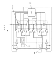
- FIG. 1 is a circuit diagram showing a voltage equalization circuit of an electric energy storage device according to a first exemplary embodiment of the present invention.
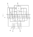
- FIG. 2 is a circuit diagram showing the voltage equalization circuit using a plurality of voltage equalization cells according to an exemplary embodiment of the present invention.
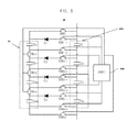
- FIG. 3 is a circuit diagram of a voltage equalization circuit divided into a module according to the exemplary embodiment of the present invention when the electric energy storage device is divided into two modules.
- FIG. 4 is a circuit diagram of the voltage equalization circuit according to the exemplary embodiment of the present invention using a voltage buffer cell.
- FIG. 5 is a circuit diagram of the voltage equalization circuit increasing an electric energy transfer rate according to the exemplary embodiment of the present invention.
- FIG. 6 is a circuit diagram of a circuit setting a current direction in FIG. 5 .
- FIG. 7 is a circuit diagram of the voltage equalization circuit that may prevent a delay during the voltage equalization process.
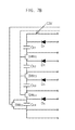
- FIG. 8 is a circuit diagram of the voltage equalization circuit that may increase the voltage equalization rate by differentiating the voltage equalization for each unit cell according to the exemplary embodiment of the present invention.
- FIG. 9 is a graph showing a potential difference during the charging/discharging process of unit cells having different capacities that are connected in series.
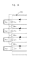
- FIG. 10 is a circuit diagram of the voltage equalization circuit having an over-voltage preventing function according to the exemplary embodiment of the present invention.
- FIG. 1 is a circuit diagram showing a voltage equalization circuit of an electric energy storage device according to a first exemplary embodiment of the present invention.
- a voltage equalization circuit 10 is configured to include an electric energy storage cell serial string (hereinafter, referred to 'unit cell serial string') CS 110 in which four electric energy storage cells (hereinafter, referred to as 'unit cell') C 1 , C 2 , C 3 , and C 4 are connected in series, a single voltage equalization cell C E , 120, switches SW 1-1 , SW 1-2 , SW 2-1 , SW 2-2 , SW 3-1 , SW 3-2 , SW 4-1 , and SW 4-2 that connect the voltage equalization cell 120 with the unit cells C 1 , C 2 , C 3 , and C 4 in parallel, switches SW E-1 and SW E-2 that connect the serial string 110 with the voltage equalization cell 120 in parallel, and a controller SWC 130 that controls the switches.
- a controller SWC 130 that controls the switches.
- the switches SW 1-1 and SW 1-2 connected with the first unit cell maintain an ON state according to a controller 130. Thereafter, the switches SW 1-1 and SW 1-2 are in an OFF state by the controller 130 and the switches SW E-1 and SW E-2 are turned-on by the controller 130 so that the voltage equalization cell 120 is connected to the serial string 110 in parallel for a predetermined time. After the switches SW E-1 and SW E-2 are again turned-off by the controller 130, the switches SW 2-1 and SW 2-2 are turned-on by the controller 130 so that the voltage equalization cell 120 is connected with the second unit cell C 2 in parallel for a predetermined time.
- the switches SW 2-1 and SW 2-2 are again turned-off by the controller 130, the switches SW E-1 and SW E-2 are turned-on by the controller 130 so that the voltage equalization cell 120 is connected to the serial string 110 in parallel for a predetermined time. Thereafter, the operation of sequentially connecting the above-mentioned unit cell with the serial string in parallel is sequentially repeated even for the number 3 unit cell and the number 4 unit cell.
- the electric energy of the serial string 110 may transferred to each unit cell C 1 , C 2 , C 3 , and C 4 of the serial string 110 using the voltage equalization cell 120, by connecting the sequentially repeated voltage equalization cell 120 with each unit cell or the voltage equalization cell 120 with the serial string in parallel.
- the voltage equalization of the serial string 110 is not made, the lower the unit cell, the higher the voltage difference with the serial string 110 becomes. As a result, the higher electric energy is transferred to the unit cell having low voltage, such that the voltage equalization is made.
- each charging voltage of the electric double layer capacitor unit cell forming the serial string is 2.4V, 2.4V, 2.8V, or 2.4V will be described below.
- the voltage of the voltage equalization cell 120 and the unit cell becomes 2.4075V when the voltage equalization cell 120 and the unit cell having voltage of 2.4V are connected in parallel, but the voltage of the voltage equalization cell 120 and the unit cell becomes 2.80719V when the voltage equalization cell 120 and the unit cell having voltage of 2.8V are connected in parallel. That is, in the case in which the voltage equalization cell 120 is connected with the unit cell having voltage of 2.4V in parallel, the increase amount in voltage is 0.0004V larger than the case in which the voltage equalization cell 120 is connected with the unit cell having voltage of 2.8V in parallel. In this case, when the capacity of the voltage equalization cell 120 is increased, the increase amount in voltage is increased.
- the unit cell having low voltage has a larger increase amount of voltage during the process in which the voltage equalization cell 120 is connected with the unit cell having low voltage in parallel , while each unit cell forming the serial string 110 drops to the same magnitude in voltage regardless of the voltage of the unit cell during the process in which the voltage equalization cell is charged by connecting the voltage equalization cell 120 with the serial string 110 in parallel.
- the unit cell in which the voltage of the serial string 110 is low is repeatedly subjected to the same voltage drop process as the voltage increase process higher than the unit cell having high voltage, such that each unit cell of the serial string 110 may achieve the voltage equalization.
- the exemplary embodiment of the present invention uses the voltage equalization cell to transfer the electric energy between the unit cell and the serial string at the one-time operation, such that the voltage equalization rate may be increased.
- a plurality of voltage equalization cells may be used.
- the exemplary embodiment including the plurality of voltage equalization cells will be described in detail with reference to FIG. 2 .
- FIG. 2 is a circuit diagram showing the voltage equalization circuit using the plurality of voltage equalization circuits according to an exemplary embodiment of the present invention.
- a voltage equalization circuit 20 is configured to include a serial string CS 210 in which four electric double layer capacitor unit cells C 1 , C 2 , C 3 , and C 4 are connected in series, two voltage equalization cells C E1 221 and C E2 222 that are connected to the serial strings, respectively, in parallel, switches SW 1-1 , SW 1-2 , SW 2-1 , SW 2-2 , SW 3-1 , SW 3-2 , SW 4-1 , and SW 4-2 that connect the voltage equalization cell 221 and 222 with each unit cell C 1 , C 2 , C 3 , and C 4 of the serial string in parallel, switches SW E1-1 , SW E1-2 , SW E2-1 , and SW E2-2 that connect the serial string 210 with the voltage equalization cells 221 and 222 in parallel, and the controller SWC 130 that controls the switches.
- the first voltage equalization cell C E1 221 is connected with the first unit cell C 1 or the second unit cell C 2 of the serial string in parallel and the second voltage equalization cell C E2 222 may be connected with the number 3 unit cell C 3 or the number 4 unit cell C 4 of the serial string.
- the controller 230 performs a control so that the switches SW E1-1 , SW E1-2 , SW E2-1 , and SW E2-2 connecting the C E1 221 and the C E2 222 with the serial string 210 in parallel are turned-off and then controls each switch SW 1-1 , SW 1-2 , SW 2-1 , SW 2-2 , SW 3-1 , SW 3-2 , SW 4-1 , or SW 4-2 so that first voltage equation cell C E1 221 is connected with the first unit cell C 1 or the second unit cell C 2 in parallel and the second voltage equalization cell C E2 222 is connected with the number 3 unit cell C 3 or the number 4 unit cell C 4 in parallel for a predetermined time.
- the controller 230 performs a control so that the switches SW 1-1 , SW 1-2 , SW 2-1 , SW 2-2 , SW 3-1 , SW 3-2, SW 4-1 , and SW 4-2 are in an OFF state in order to release the parallel connection of the voltage equation cells 221 and 222 with the unit cells and then, performs a control so that the switches SW E1-1 to SW E2-2 are in an ON state in order to connect the voltage equalization cells 221 and 222 with the serial string 210 in parallel for a predetermined time.
- the voltage equalization may be made between the unit cells C 1 , C 2 , C 3 , and C 4 within the serial string by repeating the process in which the voltage equalization cells 221 and 222 are connected with the unit cells C 1 , C 2 , C 3 , and C 4 in parallel and the voltage equalization cells 221 and 222 are then connected with the serial string 210 in parallel for a predetermined time.
- the parallel connection between voltage equalization cells 221 and 222 and the unit cells C 1 , C 2 , C 3 , and C 4 may be sequentially made.
- the parallel connection for the specific unit cell may be intensively performed according to the result of the voltage detection of each unit cell C 1 , C 2 , C 3 , and C 4 .
- switches SW E1-1 and SW E1-2 connected with the first voltage equalization cell and the switches SW E2-1 and SW E2-2 connected with the second voltage equalization cell may be independently operated from each other without synchronizing the switching operation of the first voltage equalization cell and the switching operation of the second voltage equalization cell.
- the above-mentioned exemplary embodiment is practiced using two voltage equalization cells 221 and 222, but is provided only for convenience of explanation and does not limit the present invention. Therefore, the exemplary embodiment of the present invention may be configured by increasing the number of voltage equalization cells. In this case, since the frequency of the parallel connection per hour between the unit cell and the voltage equalization cell may be increased and thus, the voltage equalization rate may be increased. As described above, increasing the number of voltage equalization cells is an effective method of preventing the voltage equalization rate from reducing in even when the number of serially connected unit cells of the series string is increased.
- the electric energy storage device When the electric energy storage device is configured by making the electric double layer capacitor or the secondary battery into the unit cell and connecting them in series, as the number of unit cells connected in series is increased, the weight and volume of the electric energy storage device is increased. Therefore, when the number of unit cells connected in series is increased, the electric energy storage device may be divided into several modules. As described above, even when the electric energy storage device is configured by again connecting several modules in series, it is efficient to use the plurality of voltage equalization cells as described above.
- FIG. 3 is a circuit diagram of the voltage equalization circuit divided into the module according to the exemplary embodiment of the present invention when the electric energy storage device is divided into two modules.
- the entire serial string CS 310 is configured by connecting 8 electric double layer capacitor unit cells C 1 to C 8 in series.
- a first module M 1 301 is configured to include a first serial string CS M1 311 in which four electric double layer capacitor unit cells C 1 , C 2 , C 3 , and C 4 are connected in series, a first voltage equalization cell C E1 321 connected with the entire serial string CS 310 in parallel, switches SW E1-1 and SW E1-2 that turn-on/off the parallel connection between the entire serial string CS 310 with the first voltage equalization cell C E1 321, switches SW 1-1 to SW 4-2 that turn-on/off the parallel connection between the first voltage equalization cell C E1 321 with the unit cells C 1 , C 2 , C 3 , and C 4 of the first serial string CS M1 311, and a first module switch controller SWC M1 331 and a first module backup switch SW M1 that control the switches included in the first module M 1 301.
- a second module M 2 302 is configured to include a second serial string CS M2 312 in which four electric double layer capacitor unit cells C 5 , C 6 , C 7 , and C 8 are connected in series, a second voltage equalization cell C E2 322 connected with the entire serial string CS 310 in parallel, switches SW E2-1 and SW E2-2 that turn-on/off the parallel connection between the entire serial string CS 310 with the second voltage equalization cell C E2 322, switches SW 5-1 to SW 8-2 that turn-on/off the parallel connection between the second voltage equalization cell C E2 321 with the unit cells C 5 , C 6 , C 7 , and C 8 of the second serial string CS M2 312, and a second module switch controller SWC M2 332 and a second module backup switch SW M2 that control the switches included in the second module M 2 302.
- the electric energy storage device is configured by connecting the first module M 1 301 and the second module M 2 302 in series and the entire serial string CS is configured by connecting the first serial string CS M1 311 with the second serial string CS M2 312 in series.
- the operation of the voltage equalization circuit 30 shown in FIG. 3 is operated as a principle equivalent to the operation of the above-mentioned voltage equalization circuit 20 with reference to FIG. 2 , but the voltage equalization circuit 20 of FIG. 2 operates all the switches by using a single controller, while the voltage equalization circuit 30 of FIG. 3 is a difference in having the switch controller SWC M1 331 and SWC M2 332 independent from each module. Further, the fact that the voltage equalization circuit 30 shown in FIG. 3 may perform the switching operation independently from each voltage equalization cell without synchronizing the switching operation of all the switches is beforehand described.
- the exemplary embodiments may be configured to be used by connecting synchronizing signal lines in order to share the synchronization signal between each module so that the voltage equalization circuit 30 may be operated by synchronizing the switches SW E1-1 to SW E2-2 used in all the modules.
- the first module backup switch SW M1 and the second module backup switch SW M2 cause the problem in the parallel connection between the voltage equalization cells 321 and 322 and the entire serial string 310 of each module, such that they are turned-on when the normal voltage equalization operation is not made, thereby performing the voltage equalization for the serial strings CS M1 311 and CS M2 312 of each module. In this case, when an alarm signal is generated, it is more effective. Therefore, the first module backup switch SW M1 and the second module backup switch SW M2 are in an OFF state while the voltage equalization is normally performed.
- each module is configured by dividing the serial string into several modules and the voltage equalization may be easily performed by using the above-mentioned voltage equalization circuit 30 for each module with reference to FIG. 3 .
- the voltage equalization operation operating by being directly connecting the voltage equalization cell with the serial string is described.
- the difference in voltage between the unit cell of the serial string and the serial string may be increased and thus, the instantaneous large current may repeatedly flow in the voltage equalization cell alternately connected between the unit cell and the serial string in parallel and the switch due to the large voltage difference.
- the large current may generate heat to cause the temperature increase, the lifespan of the device may be shortened, the price increase of the switch may be caused, and the energy efficiency of the voltage equalization circuit may be reduced and therefore, the voltage equalization circuit configured by connecting the voltage equalization cell for preventing the large current in series will be described below.
- FIG. 4 is a circuit diagram of the voltage equalization circuit using a voltage buffer cell serially connected with the voltage equalization cell according to the exemplary embodiment of the present invention.
- a voltage equalization circuit 40 is configured to include a unit cell serial string CS 410 in which four electric double layer capacitor unit cells C 1 , C 2 , C 3 , and C 4 are connected in series, a voltage equalization cell C E 421, a voltage buffer cell C VP 422, a voltage equalization cell serial string CS E 420 configured by connecting the voltage equalization cell 421 with the voltage buffer cell 422 in series, switches SW 1-1 to SW 4-2 that turn-on/off the parallel connection between the voltage equalization cell CE 421 and the unit cells C 1 , C 2 , C 3 , and C 4 of the serial string, switches SW E-1 andSW E-2 that turn-on/off the parallel connection between the serial string 410 and the voltage equalization cell string 420, and a controller SWC 430 for controlling the switches SW 1-1 to SW 4-2 , and the switchesSW E-1 and SW E-2 .
- the voltage equalization circuit 40 shown in FIG. 4 is connected the voltage equalization cell C E of the above-mentioned voltage equalization circuit 10 in series with reference to FIG. 1 , further including the voltage buffer cell C VP . That is, the basic operation of the voltage equalization circuit 40 shown in FIG. 4 is the same as the operation of the voltage equalization circuit 10 shown in FIG. 1 .
- the controller SWC 430 controls the switches SW 1-1 to SW 4-2 so that the switches SW 1-1 to SW 4-2 are again in an OFF state after the voltage equalization cell C E 421 is connected to the unit cell in parallel according to the defined order for the predetermined time. Thereafter, the controller SWC 430 controls the switches SW E-1 and SW E-2 to connect the voltage equalization cell serial string CS E 420 with the unit cell serial string 410 in parallel. As described above, when the voltage equalization cell C E 421 is connected to the unit cell in parallel, the voltage of the voltage equalization serial string CS E 420 is changed by the voltage difference between the voltage of the voltage equalization cell C E 421 and the voltage of the unit cell before being connected in parallel.
- the voltage difference corresponds to the deviations in the voltage distribution of each unit cell C 1 , C 2 , C 3 , and C 4 configuring the serial string CS 410. Therefore, when the parallel connection switches SW 1-1 to SW 4-2 between the voltage equalization cell C E 421 and the unit cell are turned-off by the controller SWC 430 and then, the parallel connection switches SW E-1 and SW E-2 between the voltage equalization cell serial string CS E 420 and the unit cell serial string CS 410 are in an ON state, the voltage difference between two serial strings is not large, such that current flowing may be greatly reduced during the process of connecting two serial strings 410 and 420 in parallel.
- the serial string CS 410 achieves the voltage equalization, there is no change in voltage even though the voltage equalization cell C E 421 is connected with the unit cell in parallel according to the defined order, such that the voltage of the voltage equalization cell serial string CS E 420 is not also changed. Therefore, the voltages of the voltage equalization cell serial string CS E 420 and the unit cell serial string CS 410 are the same and therefore, current does not flow even though two serial strings 410 and 420 are connected in parallel.
- the voltage buffer cell C VP 422 is maintained by the difference between the difference of the serial string CS 410 and the voltage of the unit cell during the voltage equalization process.
- the capacity ratio of the voltage equalization cell C E 421 and the voltage buffer cell C VP 422 of the voltage equalization cell serial string CS E 420 may be variously set, but the capacity of the voltage equalization cell C E 421 may be set to be larger than the capacity of the voltage buffer cell C VP 422.
- the electric double layer capacitor that is a capacitance of 100F and a rated voltage of the serial string CS 410 of 10V is used as each unit cell C 1 , C 2 , C 3 , and C 4
- the aluminum electrolytic capacitor that is a capacitance of 2200 ⁇ F and a rated voltage of 6.3V is used as the voltage equalization cell C E 421
- the aluminum electrolytic capacitor that is a capacitance of 680 ⁇ F and a rated voltage of 16V is used as the voltage buffer cell C VP 422
- the voltage equalization of the serial string CS 410 is performed, the voltage of the unit cells C 1 , C 2 , C 3 , and C 4 becomes 2.5V, the voltage of the voltage equalization cell C E 421 becomes 2.5V, like the voltage of the unit cells C 1 , C 2 , C 3 , and C 4 , and the voltage of the voltage buffer cell C VP 422 becomes 7.5V
- the capacitance is small when the rated voltage is increased. Therefore, when the voltage buffer cell C VP 422 is set to be same as the capacity of the voltage equalization cell C E 421, the volume and prices of the voltage buffer cell C VP 422 are increased, such that the voltage buffer cell C VP 422 may be set to have the smaller capacitance than the voltage equalization cell C E 421.
- reverse voltage may be applied to the cell having small capacitance.
- the exemplary embodiment may be configured to bypass current.
- the voltage equalization cell C E 421 and the voltage buffer cell C VP 422 may be used using different types of cells.
- the aluminum electrolytic capacitor may be used as the voltage buffer cell C VP 422 and the electric double layer capacitor or the tantalum electrolytic capacitor may be used as the voltage equalization cell C E 421.
- the voltage equalization circuit capable of increasing the electric energy transfer rate will be described below with reference to FIG. 5 .
- FIG. 5 shows a circuit diagram of the voltage equalization circuit increasing an electric energy transfer rate according to the exemplary embodiment of the present invention.
- a voltage equalization circuit 50 is configured to include a unit cell serial string CS 510 in which four electric double layer capacitor unit cells C 1 , C 2 , C 3 , and C 4 are connected in series, voltage equalization cells C E1 , C E2 , C E3 , and C E4 having the same capacitance corresponding to each unit cell C 1 , C 2 , C 3 , and C 4 of the unit cell serial string, a voltage equalization cell serial string CS E 520 configured by connecting the voltage equalization cells in series, switches SW 1-1 to SW 4-2 that turn-on/off the parallel connection between each voltage equalization cell C E1 , C E2 ,C E3 , and C E4 and each unit cell C 1 , C 2 , C 3 , and C 4 , diodes D 1 , D 2 , D 3 , and D 4 that are connected with the switches SW 1-1 ,SW 2-1 ,SW 3-1 , and SW 4-1 between the voltage equalization cells C E1
- the diodes D 1 , D 2 , D 3 , and D 4 serve to provide the flowing of current in the direction of the voltage equalization cell from the unit cell but to prevent the flowing of current in the reverse direction. That is, the unit cell performs the discharge to the voltage equalization cell but is not charged by the voltage equalization cell. That is, the diodes serve as a current direction setting unit.
- the voltage equalization cells C E1 , C E2 , C E3 , and C E4 of the voltage equalization cell serial string 520 are connected to each other in series by turning-on the switches SW E1 to SW E5 by the controller 530 for the predetermined time. Further, the voltage equalization cell serial string 520 is connected with the unit cell serial string 510 in parallel. Thereafter, the serial connection between the voltage equalization cells C E1 , C E2 , C E3 , and C E4 within the voltage equalization cell serial string 520 and the parallel connection of the voltage equalization cell serial string 520 and the unit cell serial string 510 are released, by turning-off the switches SW E1 to SW E5 by the controller 530.
- Each of the voltage equalization cells C E1 , C E2 , C E3 , and C E4 is again connected to the unit cells C 1 , C 2 , C 3 , and C 4 corresponding thereto in parallel by turning-on the switches SW 1-1 to SW 4-2 by the controller 530 for the predetermined time.
- the unit cell having high voltage among the unit cells is discharged to the corresponding voltage equalization cell during the parallel connection with the voltage equalization cell. Therefore, the voltage equalization of the unit cell serial string 510 is not performed, since the voltage of the voltage equalization cell serial string 520 rises and the voltage of the unit cell serial string 510 drops when the each unit cell C 1 , C 2 , C 3 , and C 4 corresponding to the voltage equalization cells C E1 , C E2 , C E3 , and C E4 are connected in parallel, such that current flows from the voltage equalization cell serial string 520 to the unit cell serial string 510.
- the voltage increase amount of the unit cells C 1 , C 2 , C 3 , and C 4 configuring the unit cell serial string 510 during this process is the same regardless of the voltage. Therefore, the electric energy of the unit cell having the high voltage uniformly is distributed to the unit cells C 1 , C 2 , C 3 , and C 4 of the unit cell serial string 510.
- the voltage equalization of the unit cell serial string 510 is performed by the repeated operation.
- the diodes D 1 , D 2 , D 3 , and D 4 in the above-mentioned voltage equalization circuit 50 is installed to provide the flowing of current only in the direction of the voltage equalization cells C E1 , C E2 , C E3 , and C E4 from the unit cells C 1 , C 2 , C 3 , and C 4 , but may reversely change the direction of the diode D 1 , D 2 , D 3 , and D 4 .
- the voltage equalization of the unit cell serial string 510 when the voltage equalization of the unit cell serial string 510 is not performed, the voltage of each unit cell is lower than the voltage of the corresponding voltage equalization cell while the parallel connection with the unit cells C 1 , C 2 , C 3 , and C 4 corresponding to each of the voltage equalization cells C E1 , C E2 , C E3 , and C E4 is performed, the unit cell is charged by the voltage equalization cell and the voltage of the voltage equalization cell serial string 520 is lower and the voltage of the unit cell serial string 510 rises by the operation, such that the unit cell serial string 510 charges the voltage equalization serial string 520.
- Each unit cell C 1 , C 2 , C 3 , and C 4 configuring the unit cell serial string 510 during this charging process is discharged by the same amount regardless of the voltage. Therefore, the voltage equalization is performed by transferring the electric energy of the unit cell serial string 510 from the unit cell serial string 510 to the unit cell having low voltage using the voltage equalization cells C E1 , C E2 , C E3 , and C E4 as a medium.
- the diodes D 1 , D 2 , D 3 , and D 4 are connected with the switch in series, but other current direction setting unit may be used in order to perform the role.
- FIG. 6 shows a circuit diagram of a circuit setting the current direction according to the exemplary embodiment of the present invention.
- FIG. 6 shows a current direction control circuit 60 that serves as the diode D 1 connected to the parallel connection switches SW 1-1 and SW 1-2 between the first voltage equalization cell C E1 and the first unit cell C 1 of FIG. 5 in series.
- the current direction control circuit 60 is configured to include the unit cell C 1 in which the electric energy is stored, the voltage equation cell C E1 , the switches SW 1-1 and SW 1-2 connecting the unit cell C 1 and the voltage equation cell C E1 in parallel, a voltage comparator VC measuring the potential difference between the unit cell C 1 and the voltage equalization cell C E1 , and the controller SWC controlling the switches SW 1-1 and SW 1-2 .
- the current direction may be controlled by measuring the potential difference between the voltage equalization cell C E1 and the unit cell C 1 by the voltage comparator VC and controlling the switches SW 1-1 and SW 1-2 by the controller SWC.
- the controller SWC performs a control so as not to turn-on the switches SW 1-1 and SW 1-2 when the voltage of the unit cell C 1 is lower than the voltage of the voltage equalization cell C E1 based on the potential difference between the voltage equalization cell C E1 and the unit cell C 1 measured by the voltage comparator VC during the operation of connecting the voltage equalization cell C E1 and the unit cell C 1 in parallel.
- the controller SWC may perform a control so as to turn-on the switches SW 1-1 and SW 1-2 when the voltage of the unit cell C 1 is higher than the voltage of the voltage equalization cell C E1 .
- current may be set to flow only in one direction between the voltage equalization cell C E1 and the unit cell C 1 .
- the current direction control circuit 60 may be used instead of the diode in the above-mentioned voltage equalization circuit.
- the voltage equalization cell serial string and the unit cell serial string performs the voltage equalization operation with respect to each other, such that the voltage equalization is also performed between the voltage equalization cells.
- the voltage equalization circuit capable of preventing the delay of the voltage equalization process will be described with reference to FIG. 7 .
- the circuit shown in FIG. 7A is a circuit in which resistors R E1 , R E2 , R E3 , and R E4 having a predetermined resistance value are each connected to the voltage equalization cells C E1 , C E2 , C E3 , and C E4 in parallel in the voltage equalization circuit 50 shown in FIG. 5 .
- the voltage equalization according to the circuit of FIG. 7A is one of the simplest methods among the voltage equalization methods but may generate the self discharge as the voltage equalization rate is increased.
- the resistance value is small. Since the voltage equalization cell has the smaller capacity than the unit cell, the resistor having the larger resistance value may be used, such that the amount discharged by the unit cell of the unit cell serial string is not large by the resistors R E1 , R E2 , R E3 , and R E4 connected to the voltage equalization cells in parallel.
- the circuit shown in FIG. 7B shows a circuit in which one voltage equalization cell C E4 of the voltage equalization cells C E1 , C E2 , C E3 , and C E4 connects to the switch SW E6 in parallel in the voltage equalization circuit 50 shown in FIG. 5 .
- the voltage equalization according to the circuit of FIG. 7B turns-on the switch SW E6 by the controller to discharge only one voltage equalization cell, such that the voltage of the unit cell serial string is equal to that of the voltage equalization serial string, thereby solving the delay conditions where the voltage equalization operation is not made.
- the voltage equalization rate of the voltage equalization circuit is affected by the number of voltage equalization cells, the capacity of voltage equalization cells, the parallel connection frequency per hour between the voltage equalization cells and the unit cell in the voltage equalization circuit, or the like, but the voltage equalization rate may be substantially increased by concentrating the voltage equalization to the unit cell requiring the voltage equalization.
- the voltage equalization circuit increasing the voltage equalization rate by concentrating the voltage equalization to the unit cell requiring the voltage equalization will be described with reference to FIG. 8 .
- FIG. 8 shows a circuit diagram of the voltage equalization circuit that may increase the voltage equalization rate by differentiating the voltage equalization for each unit cell according to the exemplary embodiment of the present invention.
- a voltage equalization circuit 80 is configured to include a serial string CS 810 in which four electric double layer capacitor unit cells C 1 , C 2 , C 3 , and C 4 are connected in series, a single voltage equalization cell C E 820, switches SW 1 to SW 5 in which the voltage equalization cell 820 is connected to the unit cells C 1 , C 2 , C 3 , and C 4 of the serial string in parallel, switches SW E1-1 and SW E1-2 in which the serial string 810 is connected with the voltage equalization cell 820 in parallel, switches SW P1-1 , SW P1-2 , SW P2-1 , and SW P2-2 of a polarity inversion circuit PIC 850 used for the parallel connection of the unit cell and the voltage equalization cell 820, a controller SWC 830 that controls the switches, and a unit cell voltage detector VM 840 that detects the voltage of each unit cell.
- a serial string CS 810 in which four electric double layer capacitor unit cells C 1 , C 2 , C 3 , and C 4 are connected in
- the voltage equalization circuit 80 shown in FIG. 8 is configured to further include the voltage detector 540 in the configuration of the voltage equalization circuit 10 shown in FIG. 1 and may drastically reduce the number of switches by using the polarity inversion circuit 850 when the number of serially connected unit cells of the serial string is increased.
- the voltage equalization circuit 80 shown in FIG. 8 may perform the same voltage equalization operation as the voltage equalization circuit 10 shown in FIG. 1 . Further, the voltage equalization circuit 80 may calculate the average voltage of each unit cell by using the added voltage detector 840 and detect the unit cell having the highest voltage and the lowest voltage among the unit cells. Therefore, the voltage equalization circuit 80 may perform the parallel connection on the necessary unit cells without performing the sequentially and repeatedly parallel connection during the process of performing the parallel connection between the voltage equalization cell 820 and the unit cells C 1 , C 2 , C 3 , and C 4 or the parallel connection between the voltage equalization cell 820 and the serial string 810.
- the voltage equalization circuit 80 may omit the parallel connection process between the voltage equalization cell 820 and the unit cell. Therefore, the voltage change amount of the unit cell may be increased and the parallel connection frequency per time between the voltage equalization cell 820 and each unit cell C 1 , C 2 , C 3 , and C 4 may be increased and the voltage equalization rate may be increased.
- the parallel connection between the unit cell having the lowest voltage and the voltage equalization cell 820 and the parallel between the voltage equalization cell 820 and the serial string 810 may be repeatedly and intensively performed.
- the voltage equalization capacitor repeats the parallel connection operation between the unit cell having low voltage and the remaining three unit cells by receiving the electric energy from the remaining three unit cells, respectively, other than the unit cell having low voltage for the voltage equalization.
- the exemplary embodiment of the present invention may perform the repeated parallel connection operation between the voltage equalization cell 820 and the unit cell having low voltage and the voltage equalization cell 820 and the serial string 810 in the same conditions, thereby increasing the voltage equalization rate of each unit cell according to the more intensive voltage equalization.
- the voltage equalization circuit 80 senses it to turn-off the switches connecting the voltage equalization cell 820 and the serial string 810 in parallel to prevent the reverse voltage from being applied to the voltage equalization cell 820, which may configure the exemplary embodiment in order to generate the alarm signal to the electric energy storage device operating stop signal and notify it. That is, during the process of mounting the electric energy storage device, when polarity is changed (in particular, the secondary battery is distributed and installed in the charged state), it is possible to prevent accidents due to the application of reverse polarity (in particular, the case of using the aluminum electrolytic capacitor or the tantalum electrolytic capacitor, or the like, as the voltage equalization cell) and thus, it is very effective.
- an additional function generating the alarm signal such as a logic signal may be added to the voltage detector 840 or the controller 830.
- the ultracapacitor or the secondary battery such as the electric double layer capacitor as the unit cell in order to configure the serial string it is possible to lower the unit cell capacity deviation at the time of the manufacturing but it may be inevitably cause the aging deviation due to the aging of the unit cell. That is, some degree of capacity deviations between the unit cells of the serial string according to the usage may be present. In this case, the charging and discharging behavior according to the voltage equalization method of the serial string may be changed.
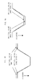
- FIG. 9 shows a graph of a potential difference during the charging/discharging process of unit cells having different capacities that are connected in series.
- FIG. 9A shows a case in which the voltage of the serial string is equalized at the charging voltage
- FIG. 9B shows a case in which the voltage of the serial string is equalized at the discharging voltage
- FIG. 9C shows a case in which the voltage equalization operation of the serial string is made overall the voltage region.
- the voltage deviations may be dispersed as the charging voltage and the discharge voltagedue to the capacity deviations between the unit cells.
- the over-voltage exceeding the rated voltage has a fatal effect on the lifespan of the cell, but the low voltage does not have a large effect on the lifespan of the cell unless the excessively reverse voltage is applied. Therefore, enhancing the voltage equalization operation is more effective in the charging voltage region that is a region having the high voltage.
- the parallel connection switching frequency is reduced at the voltage equalization circuit to increase and reduce the parallel connection frequency per time to more effectively reduce and increase the voltage equalization rate for each voltage of the serial string.
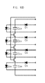
- FIG. 10 is a circuit diagram of the voltage equalization circuit having the over-voltage preventing function according to the exemplary embodiment of the present invention.
- the voltage equalization circuit shown in FIG. 10A connects the voltage equalization cell C E 120 to the switches SW S and serially connects the resistor R S to the switch for limiting current.
- the voltage equalization cell C E is connected to the unit cell in parallel, the voltage of the unit cell exceeds the set value and thus, the switch SW S is turned-on, such that the unit cell is operated to be discharged.
- the voltage equalization circuit shown in FIG. 10B connects the voltage equalization cell C E 120 to the switches SW S in parallel and serially connects the resistor R S to the zener diode D Z for limiting current.
- the switch SW 8 is turned-on and the voltage of the unit cell exceeds the set breakdown voltage of the zener diode D Z such that the unit cell is operated to perform the discharging due to the zener diode D Z .
- the voltage equalization circuit shown in FIG. 10C connects the zener diode D Z to the voltage equalization cell C E 421 in parallel.
- the voltage equalization cell C E is connected to the unit cell in parallel, the voltage of the unit cell exceeds the set breakdown voltage of the zener diode D Z such that the unit cell is operated to perform the discharging due to the zener diode D Z .
- the voltage equalization circuit shown in FIG. 10D connects the zener diodes D Z1 , D Z2 , D Z3 , and D Z4 to the voltage equalization cells C E1 , C E2 , C E3 , and C E4 in parallel.
- the voltage equalization cell is connected to the unit cell in parallel, the voltage of the unit cell exceeds the set breakdown voltage of the zener diode, such that the unit cell is operated to perform the discharging due to the zener diode.
- the voltage equalization circuit shown in FIGS. 10A to 10D may use a switching element such as a shunt resistor to provide the flowing of current when exceeding the defined voltage such as the zener diode by substituting the zener diode.
- a switching element such as a shunt resistor to provide the flowing of current when exceeding the defined voltage such as the zener diode by substituting the zener diode.
- the voltage equalization cell may have the excellent durability and the relatively large capacitance. Therefore, according to the requirements, the electric double layer capacitor, the aluminum electrolytic capacitor, the tantalum electrolytic capacitor, or the like, may be used as the voltage equalization cell.
- the description of the above-mentioned exemplary embodiment of the present invention describes the case in which the electric double layer capacitor as the electric energy storage cell, this is only for convenience of explanation and the exemplary embodiment of the present invention is not limited the object of the electric energy storage cell to the electric double layer capacity.
- the ultracapacitor such as the electric double layer capacitor according to the exemplary embodiment of the present invention
- the case in which the electric energy storage cells such as the secondary battery or the electrolytic condenser are connected in series may be used.
- the exemplary embodiment of the present invention uses the case in which four unit cells are connected in series, the present invention does not specifically limit the serial number.
- the exemplary embodiment of the present invention provides the voltage equalization method between the electric energy storage cells in the electric energy storage devices in which the electric energy storage cells are connected in series.
- An example of the electric energy storage cells may include an ultracapacitor such as an electric double layer capacitor, a lead acid battery, an NiMH battery, an NiCd battery, a lithium ion battery, an aluminum electrolytic capacitor, or the like.
Landscapes
- Engineering & Computer Science (AREA)
- Power Engineering (AREA)
- Physics & Mathematics (AREA)
- General Physics & Mathematics (AREA)
- Charge And Discharge Circuits For Batteries Or The Like (AREA)
Applications Claiming Priority (2)
| Application Number | Priority Date | Filing Date | Title |
|---|---|---|---|
| KR1020080105387A KR101011235B1 (ko) | 2008-10-27 | 2008-10-27 | 전기에너지 저장장치의 전압균등화회로 |
| PCT/KR2009/006016 WO2010076955A2 (ko) | 2008-10-27 | 2009-10-19 | 전기에너지 저장장치의 전압균등화회로 |
Publications (1)
| Publication Number | Publication Date |
|---|---|
| EP2352218A2 true EP2352218A2 (de) | 2011-08-03 |
Family
ID=42273769
Family Applications (1)
| Application Number | Title | Priority Date | Filing Date |
|---|---|---|---|
| EP20090836276 Withdrawn EP2352218A2 (de) | 2008-10-27 | 2009-10-19 | Spannungsausgleichsschaltkreis für eine stromspeichervorrichtung |
Country Status (4)
| Country | Link |
|---|---|
| US (1) | US20110204722A1 (de) |
| EP (1) | EP2352218A2 (de) |
| KR (1) | KR101011235B1 (de) |
| WO (1) | WO2010076955A2 (de) |
Cited By (7)
| Publication number | Priority date | Publication date | Assignee | Title |
|---|---|---|---|---|
| WO2012143396A1 (en) * | 2011-04-19 | 2012-10-26 | 4Esys | A system and method for balancing energy storage devices |
| EP2584685A1 (de) * | 2011-10-20 | 2013-04-24 | Siemens Aktiengesellschaft | Symmetrierungsschaltung für in Reihe geschalteten Zwischenkreiskondensatoren, und Verfahren zu deren Betrieb |
| EP2562907A3 (de) * | 2011-08-22 | 2014-09-17 | Seiko Instruments Inc. | Zellausgleichsvorrichtung und Batteriesystem |
| US9577442B2 (en) | 2010-12-06 | 2017-02-21 | Sii Semiconductor Corporation | Cell balance device and battery system |
| EP2548281B1 (de) * | 2010-03-13 | 2017-08-16 | Continental Automotive GmbH | Verfahren zum ladungsausgleich in einem batteriesystem und batteriesystem mit einer ladungsausgleichsschaltung |
| US10587126B2 (en) | 2013-09-26 | 2020-03-10 | Murata Manufacturing Co., Ltd. | Power storage device, power storage control device, and power storage control method |
| WO2021152627A1 (en) | 2020-01-31 | 2021-08-05 | Exicom Tele-Systems Limited | System for balancing plurality of cells within battery pack and method thereof |
Families Citing this family (23)
| Publication number | Priority date | Publication date | Assignee | Title |
|---|---|---|---|---|
| KR101140244B1 (ko) * | 2010-06-03 | 2012-05-02 | 주식회사 이랜텍 | 축전지 팩 모듈 |
| KR101750055B1 (ko) * | 2010-09-13 | 2017-06-22 | 삼성전자주식회사 | 보조 전원 장치, 그것을 포함하는 메모리 시스템, 및 그것의 셀 균형 방법 |
| US9496724B2 (en) | 2010-09-23 | 2016-11-15 | Stmicroelectronics Application Gmbh | Active battery balancing circuit and method of balancing an electric charge in a plurality of cells of a battery |
| US8957624B2 (en) | 2011-01-20 | 2015-02-17 | Valence Technology, Inc. | Rechargeable battery systems and rechargeable battery system operational methods |
| US8773068B2 (en) | 2011-01-20 | 2014-07-08 | Valence Technology, Inc. | Rechargeable battery systems and rechargeable battery system operational methods |
| KR101246145B1 (ko) | 2011-02-22 | 2013-04-05 | 킴스테크날리지 주식회사 | 전기에너지 저장장치의 전압균등화회로 |
| JP5641006B2 (ja) * | 2011-08-31 | 2014-12-17 | ソニー株式会社 | 蓄電装置 |
| JP6034602B2 (ja) * | 2012-07-02 | 2016-11-30 | ローム株式会社 | 制御回路、キャパシタモジュール、電池モジュール、電源回路、それらを用いた家庭用蓄電池および車両 |
| KR101865969B1 (ko) * | 2012-12-17 | 2018-06-11 | 현대자동차주식회사 | 배터리전압 밸런싱장치 및 방법 |
| KR101462385B1 (ko) * | 2013-04-19 | 2014-11-19 | 나라셀텍(주) | 전력저장장치의 전압검출회로 |
| EP3026750A1 (de) * | 2014-11-28 | 2016-06-01 | Siemens Aktiengesellschaft | Verfahren zum Symmetrieren eines Energiespeichersystems |
| US10931123B2 (en) | 2015-03-04 | 2021-02-23 | Maxwell Technologies, Inc. | Systems and methods for improving cell balancing and cell failure detection |
| DE102016218232B4 (de) | 2016-09-22 | 2024-02-15 | Volkswagen Aktiengesellschaft | Positionsbestimmungssystem für eine mobile Einheit, Fahrzeug und Verfahren zum Betreiben eines Positionsbestimmungssystems |
| US10574076B2 (en) * | 2016-12-20 | 2020-02-25 | Maxwell Technologies, Inc. | Systems and methods for improving cell balancing and cell failure detection |
| JP7116068B2 (ja) * | 2017-01-25 | 2022-08-09 | ユーキャップ パワー インコーポレイテッド | キャパシタモジュールバランシング及びメンテナンスのためのシステム及び方法 |
| CN106910746B (zh) | 2017-03-08 | 2018-06-19 | 长江存储科技有限责任公司 | 一种3d nand存储器件及其制造方法、封装方法 |
| CN108988469B (zh) * | 2017-05-31 | 2021-08-13 | 常州市派腾电子技术服务有限公司 | 一种电池电路、电池装置、电子烟和供电控制方法 |
| DE102017009007A1 (de) * | 2017-09-26 | 2019-03-28 | Borgward Trademark Holdings Gmbh | Verfahren zum Ausgleichen einer Antriebsbatterie, zugehörige Einrichtung und Fahrzeug |
| CN115735313A (zh) * | 2020-06-30 | 2023-03-03 | 京瓷Avx元器件公司 | 用于平衡多个超级电容器的系统和方法 |
| CN112688374B (zh) * | 2020-12-03 | 2022-09-20 | 华南理工大学 | 基于超级电容储能转移的锂电池组主动均衡系统 |
| US12136837B1 (en) * | 2020-12-08 | 2024-11-05 | Bobbie Wilson | Charge balancing of parallel strings with zener diode and light emitting diode between cell terminal of the battery strings |
| KR102690705B1 (ko) | 2022-10-11 | 2024-08-05 | (주)투비시스템 | 다중 센서 융합형 IoT 디바이스 기반 제조 설비 네트워크의 예지 보전 및 보안 관리 시스템 |
| US20250239869A1 (en) * | 2024-01-19 | 2025-07-24 | Caterpillar Inc. | Active inter-cell balancing method |
Family Cites Families (13)
| Publication number | Priority date | Publication date | Assignee | Title |
|---|---|---|---|---|
| US5666041A (en) * | 1996-08-27 | 1997-09-09 | The University Of Toledo | Battery equalization circuit with ramp converter |
| TW502900U (en) * | 1998-11-30 | 2002-09-11 | Ind Tech Res Inst | Battery charging equalizing device |
| US6150795A (en) * | 1999-11-05 | 2000-11-21 | Power Designers, Llc | Modular battery charge equalizers and method of control |
| JP2001178008A (ja) * | 1999-12-20 | 2001-06-29 | Nec Corp | セルバランス調整回路、セル電圧異常検出回路、セルバランス調整方法およびセル電圧異常検出方法 |
| JP2001289886A (ja) * | 2000-04-03 | 2001-10-19 | Sanyo Electric Co Ltd | 電池電圧測定装置 |
| DE10101542A1 (de) * | 2000-09-25 | 2002-04-11 | Amita Technologies Inc Ltd | Vorrichtung zum Spannungsabgleich an einer in Reihe geschalteten Akkumulatoranordnung und Verfahren dafür |
| US7288919B2 (en) * | 2001-10-01 | 2007-10-30 | Sanken Electric Co., Ltd. | Voltage balance circuit, voltage detective circuit, voltage balancing method, and voltage detecting method |
| US7245108B2 (en) * | 2002-11-25 | 2007-07-17 | Tiax Llc | System and method for balancing state of charge among series-connected electrical energy storage units |
| DE10346325A1 (de) * | 2003-10-06 | 2005-05-04 | Siemens Ag | Schaltvorrichtung zum bidirektionalen Ladungsausgleich zwischen Energiespeichern |
| JP3795499B2 (ja) * | 2003-12-26 | 2006-07-12 | 富士重工業株式会社 | 蓄電素子の電圧均等化装置 |
| KR20060085463A (ko) * | 2005-01-24 | 2006-07-27 | 주식회사 네스캡 | 전기에너지 저장장치의 전압 균등화 방법 및 전기 에너지저장장치 |
| KR100831160B1 (ko) * | 2005-04-15 | 2008-05-20 | 주식회사 엘지화학 | 배터리 셀의 밸런싱을 위한 스위칭 회로 |
| JP2007020368A (ja) * | 2005-07-11 | 2007-01-25 | Komatsu Ltd | 蓄電素子の電圧均等化装置および方法 |
-
2008
- 2008-10-27 KR KR1020080105387A patent/KR101011235B1/ko not_active Expired - Fee Related
-
2009
- 2009-10-19 EP EP20090836276 patent/EP2352218A2/de not_active Withdrawn
- 2009-10-19 WO PCT/KR2009/006016 patent/WO2010076955A2/ko not_active Ceased
- 2009-10-19 US US13/126,458 patent/US20110204722A1/en not_active Abandoned
Non-Patent Citations (1)
| Title |
|---|
| See references of WO2010076955A2 * |
Cited By (12)
| Publication number | Priority date | Publication date | Assignee | Title |
|---|---|---|---|---|
| EP2548281B1 (de) * | 2010-03-13 | 2017-08-16 | Continental Automotive GmbH | Verfahren zum ladungsausgleich in einem batteriesystem und batteriesystem mit einer ladungsausgleichsschaltung |
| US9577442B2 (en) | 2010-12-06 | 2017-02-21 | Sii Semiconductor Corporation | Cell balance device and battery system |
| WO2012143396A1 (en) * | 2011-04-19 | 2012-10-26 | 4Esys | A system and method for balancing energy storage devices |
| EP2562907A3 (de) * | 2011-08-22 | 2014-09-17 | Seiko Instruments Inc. | Zellausgleichsvorrichtung und Batteriesystem |
| US9000726B2 (en) | 2011-08-22 | 2015-04-07 | Seiko Instruments Inc. | Cell balance device and battery system |
| EP2584685A1 (de) * | 2011-10-20 | 2013-04-24 | Siemens Aktiengesellschaft | Symmetrierungsschaltung für in Reihe geschalteten Zwischenkreiskondensatoren, und Verfahren zu deren Betrieb |
| US10587126B2 (en) | 2013-09-26 | 2020-03-10 | Murata Manufacturing Co., Ltd. | Power storage device, power storage control device, and power storage control method |
| EP3051661B1 (de) * | 2013-09-26 | 2021-02-24 | Murata Manufacturing Co., Ltd. | Stromspeicherungsvorrichtung und stromspeicherungssteuerungsverfahren |
| WO2021152627A1 (en) | 2020-01-31 | 2021-08-05 | Exicom Tele-Systems Limited | System for balancing plurality of cells within battery pack and method thereof |
| CN115039316A (zh) * | 2020-01-31 | 2022-09-09 | 爱克斯康电子系统有限公司 | 用于平衡电池组内的多个电池单元的系统及其方法 |
| EP3984115A4 (de) * | 2020-01-31 | 2023-07-05 | Exicom Tele-Systems Limited | System zum auswuchten mehrerer zellen innerhalb eines akkusatzes und verfahren dafür |
| CN115039316B (zh) * | 2020-01-31 | 2025-11-25 | 爱克斯康电子系统有限公司 | 用于平衡电池组内的多个电池单元的系统及其方法 |
Also Published As
| Publication number | Publication date |
|---|---|
| KR20100046522A (ko) | 2010-05-07 |
| KR101011235B1 (ko) | 2011-01-26 |
| WO2010076955A3 (ko) | 2010-08-19 |
| US20110204722A1 (en) | 2011-08-25 |
| WO2010076955A2 (ko) | 2010-07-08 |
Similar Documents
| Publication | Publication Date | Title |
|---|---|---|
| EP2352218A2 (de) | Spannungsausgleichsschaltkreis für eine stromspeichervorrichtung | |
| EP3809553B1 (de) | Batteriesystem | |
| EP3540900B1 (de) | Vorrichtung und verfahren zur batteriemodulentzerrung | |
| JP6813614B2 (ja) | インテリジェント電池の直流充電 | |
| JP6840525B2 (ja) | バッテリ制御方法、バッテリ制御装置、及びバッテリパック | |
| ES2394629T3 (es) | Dispositivo de almacenamiento de carga que usa condensadores y su método de control | |
| EP2590296B1 (de) | Energiespeichersystem | |
| CN107251354B (zh) | 电动车辆配电系统 | |
| EP2826128A1 (de) | Verfahren und system zum ausgleich von zellen mit variablem umleitungsstrom | |
| US11158888B2 (en) | Management device and power storage system | |
| EP2315336A1 (de) | Elektrizitätsspeichersystem | |
| US20150349551A1 (en) | Bottom Based Balancing in Lithium Ion System | |
| TWI433425B (zh) | Battery charge and discharge balance of the circuit | |
| US11588185B2 (en) | Management device and power supply system | |
| KR102151652B1 (ko) | 척컨버터 토폴로지를 이용한 리튬이온 전지 셀밸런싱 장치 | |
| JP2013078242A (ja) | 電源装置 | |
| US9948117B2 (en) | Battery balancing apparatus and battery balancing method thereof | |
| US9337670B2 (en) | Circuit and method for battery equalization | |
| US20170244259A1 (en) | Voltage detecting device | |
| JP2016119839A (ja) | 蓄電池装置、蓄電池装置の制御方法及び制御プログラム | |
| CN107004514B (zh) | 用于均衡能量存储器系统的方法 | |
| JP6356518B2 (ja) | バッテリ管理システムおよび方法 | |
| JP7097456B2 (ja) | 蓄電システムおよび充電制御方法 | |
| KR20180047461A (ko) | 배터리 셀 밸런싱 장치 | |
| US12155257B2 (en) | Battery module, battery unit, and converter device |
Legal Events
| Date | Code | Title | Description |
|---|---|---|---|
| PUAI | Public reference made under article 153(3) epc to a published international application that has entered the european phase |
Free format text: ORIGINAL CODE: 0009012 |
|
| 17P | Request for examination filed |
Effective date: 20110520 |
|
| AK | Designated contracting states |
Kind code of ref document: A2 Designated state(s): AT BE BG CH CY CZ DE DK EE ES FI FR GB GR HR HU IE IS IT LI LT LU LV MC MK MT NL NO PL PT RO SE SI SK SM TR |
|
| DAX | Request for extension of the european patent (deleted) | ||
| STAA | Information on the status of an ep patent application or granted ep patent |
Free format text: STATUS: THE APPLICATION IS DEEMED TO BE WITHDRAWN |
|
| 18D | Application deemed to be withdrawn |
Effective date: 20140501 |