EP2352136A1 - System for monitoring the area around a vehicle - Google Patents
System for monitoring the area around a vehicle Download PDFInfo
- Publication number
- EP2352136A1 EP2352136A1 EP09823207A EP09823207A EP2352136A1 EP 2352136 A1 EP2352136 A1 EP 2352136A1 EP 09823207 A EP09823207 A EP 09823207A EP 09823207 A EP09823207 A EP 09823207A EP 2352136 A1 EP2352136 A1 EP 2352136A1
- Authority
- EP
- European Patent Office
- Prior art keywords
- vehicle
- notification
- monitoring
- difference
- area around
- Prior art date
- Legal status (The legal status is an assumption and is not a legal conclusion. Google has not performed a legal analysis and makes no representation as to the accuracy of the status listed.)
- Granted
Links
Images


Classifications
-
- B—PERFORMING OPERATIONS; TRANSPORTING
- B60—VEHICLES IN GENERAL
- B60R—VEHICLES, VEHICLE FITTINGS, OR VEHICLE PARTS, NOT OTHERWISE PROVIDED FOR
- B60R1/00—Optical viewing arrangements; Real-time viewing arrangements for drivers or passengers using optical image capturing systems, e.g. cameras or video systems specially adapted for use in or on vehicles
- B60R1/20—Real-time viewing arrangements for drivers or passengers using optical image capturing systems, e.g. cameras or video systems specially adapted for use in or on vehicles
- B60R1/22—Real-time viewing arrangements for drivers or passengers using optical image capturing systems, e.g. cameras or video systems specially adapted for use in or on vehicles for viewing an area outside the vehicle, e.g. the exterior of the vehicle
- B60R1/23—Real-time viewing arrangements for drivers or passengers using optical image capturing systems, e.g. cameras or video systems specially adapted for use in or on vehicles for viewing an area outside the vehicle, e.g. the exterior of the vehicle with a predetermined field of view
- B60R1/24—Real-time viewing arrangements for drivers or passengers using optical image capturing systems, e.g. cameras or video systems specially adapted for use in or on vehicles for viewing an area outside the vehicle, e.g. the exterior of the vehicle with a predetermined field of view in front of the vehicle
-
- B—PERFORMING OPERATIONS; TRANSPORTING
- B60—VEHICLES IN GENERAL
- B60R—VEHICLES, VEHICLE FITTINGS, OR VEHICLE PARTS, NOT OTHERWISE PROVIDED FOR
- B60R1/00—Optical viewing arrangements; Real-time viewing arrangements for drivers or passengers using optical image capturing systems, e.g. cameras or video systems specially adapted for use in or on vehicles
- B60R1/20—Real-time viewing arrangements for drivers or passengers using optical image capturing systems, e.g. cameras or video systems specially adapted for use in or on vehicles
- B60R1/30—Real-time viewing arrangements for drivers or passengers using optical image capturing systems, e.g. cameras or video systems specially adapted for use in or on vehicles providing vision in the non-visible spectrum, e.g. night or infrared vision
-
- G—PHYSICS
- G06—COMPUTING OR CALCULATING; COUNTING
- G06V—IMAGE OR VIDEO RECOGNITION OR UNDERSTANDING
- G06V20/00—Scenes; Scene-specific elements
- G06V20/50—Context or environment of the image
- G06V20/56—Context or environment of the image exterior to a vehicle by using sensors mounted on the vehicle
- G06V20/58—Recognition of moving objects or obstacles, e.g. vehicles or pedestrians; Recognition of traffic objects, e.g. traffic signs, traffic lights or roads
-
- B—PERFORMING OPERATIONS; TRANSPORTING
- B60—VEHICLES IN GENERAL
- B60R—VEHICLES, VEHICLE FITTINGS, OR VEHICLE PARTS, NOT OTHERWISE PROVIDED FOR
- B60R2300/00—Details of viewing arrangements using cameras and displays, specially adapted for use in a vehicle
- B60R2300/10—Details of viewing arrangements using cameras and displays, specially adapted for use in a vehicle characterised by the type of camera system used
- B60R2300/103—Details of viewing arrangements using cameras and displays, specially adapted for use in a vehicle characterised by the type of camera system used using camera systems provided with artificial illumination device, e.g. IR light source
-
- B—PERFORMING OPERATIONS; TRANSPORTING
- B60—VEHICLES IN GENERAL
- B60R—VEHICLES, VEHICLE FITTINGS, OR VEHICLE PARTS, NOT OTHERWISE PROVIDED FOR
- B60R2300/00—Details of viewing arrangements using cameras and displays, specially adapted for use in a vehicle
- B60R2300/10—Details of viewing arrangements using cameras and displays, specially adapted for use in a vehicle characterised by the type of camera system used
- B60R2300/105—Details of viewing arrangements using cameras and displays, specially adapted for use in a vehicle characterised by the type of camera system used using multiple cameras
-
- B—PERFORMING OPERATIONS; TRANSPORTING
- B60—VEHICLES IN GENERAL
- B60R—VEHICLES, VEHICLE FITTINGS, OR VEHICLE PARTS, NOT OTHERWISE PROVIDED FOR
- B60R2300/00—Details of viewing arrangements using cameras and displays, specially adapted for use in a vehicle
- B60R2300/20—Details of viewing arrangements using cameras and displays, specially adapted for use in a vehicle characterised by the type of display used
- B60R2300/205—Details of viewing arrangements using cameras and displays, specially adapted for use in a vehicle characterised by the type of display used using a head-up display
-
- B—PERFORMING OPERATIONS; TRANSPORTING
- B60—VEHICLES IN GENERAL
- B60R—VEHICLES, VEHICLE FITTINGS, OR VEHICLE PARTS, NOT OTHERWISE PROVIDED FOR
- B60R2300/00—Details of viewing arrangements using cameras and displays, specially adapted for use in a vehicle
- B60R2300/30—Details of viewing arrangements using cameras and displays, specially adapted for use in a vehicle characterised by the type of image processing
- B60R2300/301—Details of viewing arrangements using cameras and displays, specially adapted for use in a vehicle characterised by the type of image processing combining image information with other obstacle sensor information, e.g. using RADAR/LIDAR/SONAR sensors for estimating risk of collision
-
- B—PERFORMING OPERATIONS; TRANSPORTING
- B60—VEHICLES IN GENERAL
- B60R—VEHICLES, VEHICLE FITTINGS, OR VEHICLE PARTS, NOT OTHERWISE PROVIDED FOR
- B60R2300/00—Details of viewing arrangements using cameras and displays, specially adapted for use in a vehicle
- B60R2300/30—Details of viewing arrangements using cameras and displays, specially adapted for use in a vehicle characterised by the type of image processing
- B60R2300/304—Details of viewing arrangements using cameras and displays, specially adapted for use in a vehicle characterised by the type of image processing using merged images, e.g. merging camera image with stored images
- B60R2300/305—Details of viewing arrangements using cameras and displays, specially adapted for use in a vehicle characterised by the type of image processing using merged images, e.g. merging camera image with stored images merging camera image with lines or icons
-
- B—PERFORMING OPERATIONS; TRANSPORTING
- B60—VEHICLES IN GENERAL
- B60R—VEHICLES, VEHICLE FITTINGS, OR VEHICLE PARTS, NOT OTHERWISE PROVIDED FOR
- B60R2300/00—Details of viewing arrangements using cameras and displays, specially adapted for use in a vehicle
- B60R2300/30—Details of viewing arrangements using cameras and displays, specially adapted for use in a vehicle characterised by the type of image processing
- B60R2300/307—Details of viewing arrangements using cameras and displays, specially adapted for use in a vehicle characterised by the type of image processing virtually distinguishing relevant parts of a scene from the background of the scene
-
- B—PERFORMING OPERATIONS; TRANSPORTING
- B60—VEHICLES IN GENERAL
- B60R—VEHICLES, VEHICLE FITTINGS, OR VEHICLE PARTS, NOT OTHERWISE PROVIDED FOR
- B60R2300/00—Details of viewing arrangements using cameras and displays, specially adapted for use in a vehicle
- B60R2300/80—Details of viewing arrangements using cameras and displays, specially adapted for use in a vehicle characterised by the intended use of the viewing arrangement
- B60R2300/8093—Details of viewing arrangements using cameras and displays, specially adapted for use in a vehicle characterised by the intended use of the viewing arrangement for obstacle warning
Definitions
- the image processing unit 1 is connected to a speaker (corresponding to "the sound output device” of the present invention) 6 for use in outputting auditory notification information with a sound or the like and a HUD (head-up display, corresponding to "the image display device” of the present invention) 7, which is placed in the vicinity of the front window in order to display captured images taken by the infrared cameras 2R and 2L and visual notification information.
- a speaker corresponding to "the sound output device” of the present invention
- HUD head-up display, corresponding to "the image display device” of the present invention
- the infrared image signals of the infrared cameras 2R and 2L are input to the image processing unit 1, the infrared image signals are AD-converted, gray-scale images are generated on the basis of the AD-converted infrared image signals, and a reference gray-scale image (right image) is binarized. Thereafter, the area where the object exists in the binary image is extracted as an object area S (STEP 002 of Fig. 3 ).
- the object is decided not to be a human (NO in STEP 014 of Fig. 3 )
- the object is a human or a four-footed animal on the basis of the shape or size of the object area S or a feature quantity such as a luminance distribution on the gray scale image.
Landscapes
- Engineering & Computer Science (AREA)
- Multimedia (AREA)
- Mechanical Engineering (AREA)
- Physics & Mathematics (AREA)
- General Physics & Mathematics (AREA)
- Theoretical Computer Science (AREA)
- Traffic Control Systems (AREA)
- Image Analysis (AREA)
- Image Processing (AREA)
Abstract


Description
- The present invention relates to a system for monitoring the area around a vehicle, which uses a captured image taken by an imaging device mounted on the vehicle, so that a notifying device notifies a passenger in the vehicle of the presence of an object in the case of high contacting possibility between the vehicle and the object.
- There has been suggested a system for monitoring the area around a vehicle, which calculates a motion vector in the real space of an object on the basis of time-series positional data of the object such as an animal existing in the area around the vehicle, decides whether the contacting possibility between the vehicle and the object is high or low on the basis of the motion vector, and notifies the driver that the contacting possibility is high if decided so (Refer to Japanese Patent Application Laid-Open No.
2001-006096 - Meanwhile, although the kind of an object is useful information for the driver of a vehicle when the driver recognizes that the object is a human, such as a pedestrian or a passenger on a bicycle, or a four-footed animal such as a deer or a dog, the driver is not able to recognize the kind of the object only with simple notification.
- Therefore, it is an object of the present invention to provide a system for monitoring the area around a vehicle capable of notifying the passenger in the vehicle of the presence of an object so that the passenger is able to recognize the kind of the object.
- To solve the above problem, the present invention provides a system for monitoring the area around a vehicle, which uses a captured image taken by an imaging device mounted on the vehicle, so that a notification device notifies a passenger in the vehicle of the presence of an object in the case of high contacting possibility between the vehicle and the object, the system including: an object extracting unit, which extracts an image area corresponding to the object as an object area from the captured image; an object kind deciding unit, which decides the kind of the object on the basis of the shape or the shape and size of the object area extracted by the object extracting unit; and an notification control unit, which causes the notification device to give notification on the presence of the object in a different mode according to a difference in the kind of the object decided by the object kind deciding unit.
- According to the system for monitoring the area around a vehicle of the present invention, the passenger in the vehicle is able to recognize not only the presence but also the kind of the object according to a difference in the mode of notification indicating the presence of the object. Here, the "captured image" is a concept including not only a captured original image itself but also a processed image obtained by processing the original image.
- The system for monitoring the area around a vehicle of the present invention may include an image display device, which displays images around the vehicle, as the notification device, so that the image display device displays the presence of the object in a different mode according to a difference in the kind of the object decided by the object kind deciding unit.
- According to the system for monitoring the area around a vehicle having the configuration, the passenger in the vehicle is able to be visually notified of not only the presence but also the kind of the object in images around the vehicle, according to a difference in the display mode of the presence of the object.
- The system for monitoring the area around a vehicle of the present invention may include a sound output device, which outputs a sound indicating the presence of the object, as the notification device, so that the sound output device outputs the sound indicating the presence of the object in a different mode according to a difference in the kind of the object decided by the object kind deciding unit.
- According to the system for monitoring the area around a vehicle having the configuration, the passenger in the vehicle is able to aurally recognize not only the presence but also the kind of the object according to a difference in the output mode of a sound indicating the presence of the object.
- The system for monitoring the area around a vehicle of the present invention may include a distance measuring unit, which measures a distance between the vehicle and the object, so that the notification control unit causes the notification device to give notification on the presence of the object in a different mode according to a difference in the kind of the object with a requirement that the distance measured by the distance measuring unit is a reference distance or less.
- According to the system for monitoring the area around a vehicle having the configuration, in view of the fact that the farther the object is from the vehicle, the lower the decision accuracy of the kind of the object is, the driver of the vehicle is notified of the presence of the object in a different mode according to a difference in the kind of the object only in a state where the decision accuracy is high to some extent. This prevents a situation where an erroneous decision on the kind of the object obtained by the system for monitoring the area around a vehicle causes the driver to be notified of the presence of the obj ect in a wrong mode.
- The system for monitoring the area around a vehicle according to the present invention may include a distance measuring unit, which measures a distance between the vehicle and the object, so that the notification control unit causes the notification device to give notification on the presence of the object in a different mode according to not only a difference in the kind of the object decided by the object kind deciding unit but also the degree of the distance measured by the distance measuring unit.
- According to the system for monitoring the area around a vehicle having the configuration, the passenger in the vehicle is able to recognize not only the presence and kind of the object but also the degree of the distance between the vehicle and the object according to a difference in the mode of the notification indicating the presence of the obj ect.
- The system for monitoring the area around a vehicle of the present invention may include a vehicle speed measuring unit, which measures the speed of the vehicle, so that the notification control unit causes the notification device to give notification on the presence of the object in a different mode according to not only a difference in the kind of the object decided by the object kind deciding unit but also the level of the speed of the vehicle measured by the vehicle speed measuring unit.
- According to the system for monitoring the area around a vehicle having the configuration, the passenger in the vehicle is able to recognize not only the presence and kind of the object but also the level of the speed of the vehicle according to a difference in the mode of the notification indicating the presence of the object.
-
-
Fig. 1 is a configuration explanatory diagram of a system for monitoring the area around a vehicle according to the present invention; -
Fig. 2 is an explanatory diagram of the vehicle mounted with the system for monitoring the area around a vehicle; -
Fig. 3 is a flowchart illustrating the functions of the system for monitoring the area around a vehicle; and -
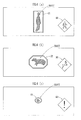
Fig. 4 is an explanatory diagram of different notification processes. - Preferred embodiments of a system for monitoring the area around a vehicle of the present invention will be described below.
- First, the configuration of the system for monitoring the area around a vehicle of this embodiment will be described. The system for monitoring the area around a vehicle includes an
image processing unit 1 illustrated inFig. 1 andFig. 2 . Theimage processing unit 1 is connected to a pair of right and leftinfrared cameras vehicle 10, and theimage processing unit 1 is connected to, as a sensor detecting the running condition of thevehicle 10, ayaw rate sensor 3 which detects the yaw rate of thevehicle 10, a vehicle speed sensor 4 which detects the running speed of the vehicle 10 (vehicle speed), and a brake sensor 5 which detects whether a brake operation of thevehicle 10 is performed. - Moreover, the
image processing unit 1 is connected to a speaker (corresponding to "the sound output device" of the present invention) 6 for use in outputting auditory notification information with a sound or the like and a HUD (head-up display, corresponding to "the image display device" of the present invention) 7, which is placed in the vicinity of the front window in order to display captured images taken by theinfrared cameras - If a distance from the object is measured by a radar, only one infrared camera may be mounted on the
vehicle 10. Instead of or in addition to the HUD, a display that displays the running condition including the vehicle speed of thevehicle 10 or a display of the in-vehicle navigation device may be used as the image display device. - The
image processing unit 1 is made of an ECU (electronic control unit) including an A-D converter, the CPU, memories such as a RAM and a ROM, I/O circuits, a bus for connecting these parts together. The image processing unit 1 (more specifically, the CPU, which performs arithmetic processing based on a program stored in a memory or a storage device) constitute "the object extracting unit", "the object kind deciding unit", and "the notification control unit" of the present invention. - The AD converter circuit digitizes analog signals output from the
infrared cameras yaw rate sensor 3, the vehicle speed sensor 4, and the brake sensor 5. Based on the digitized data, the CPU detects an object such as a human (a pedestrian or a passenger on a bicycle or on a two-wheel motor vehicle) or a four-footed animal (a deer, a horse, a dog, or the like) and notifies the driver of the presence of the object or the level of contacting possibility between thevehicle 10 and the object through thespeaker 6 or theHUD 7 if the detected object satisfies a predetermined notification requirement. - As illustrated in
Fig. 2 , theinfrared cameras Fig. 2 ) of thevehicle 10 to take images of the front of thevehicle 10. The rightinfrared camera 2R is placed to the right from the center in the vehicle width direction of thevehicle 10, and the leftinfrared camera 2L is placed to the left from the center in the vehicle width direction of thevehicle 10. Their positions are symmetrical to the center in the vehicle width direction of thevehicles 10. Theinfrared cameras vehicle 10 in parallel to each other and the optical axes have the same height from the road surface. Theinfrared cameras infrared cameras - The following describes the functions of the system for monitoring the area around a vehicle having the above configuration. The image processing is disclosed in detail in Japanese Patent Application Laid-Open No.
2001-006096 2007-310705 - First, the infrared image signals of the
infrared cameras image processing unit 1, the infrared image signals are AD-converted, gray-scale images are generated on the basis of the AD-converted infrared image signals, and a reference gray-scale image (right image) is binarized. Thereafter, the area where the object exists in the binary image is extracted as an object area S (STEP 002 ofFig. 3 ). - Specifically, pixels constituting a high-luminance area of the binary image are converted to run length data, a label (an identifier) is attached to each of the lines having overlapping in the vertical direction of the reference image, and each of the lines is extracted as the object area S. This enables an extraction of the high-luminance area, which is made of a group of high-luminance pixels (pixels having a pixel value of 1) as illustrated with diagonal lines in
Fig. 4(a) to 4(c) , as the object area S. - Subsequently, a calculation is made on the center-of-gravity position (the position on the reference image), the planar dimensions, and the aspect ratio of a circumscribed quadrangle of each object. Further, the object is tracked at time intervals to decide the identity of the object over the respective arithmetic processing cycles of the
image processing unit 1. Moreover, outputs from the vehicle speed sensor 4 and the yaw rate sensor 5 (the detected value of the vehicle speed and the detected value of the yaw rate) are read. - Further, in parallel with the calculation of the aspect ratio of the circumscribed quadrangle and the tracking of the object at time intervals, the area corresponding to each object (for example, the area of the circumscribed quadrangle of the object) is extracted as a search image from the reference image. Moreover, the correlation operation is performed to search for and extract the image corresponding to the search image (the corresponding image) from the left image.
- Further, a real space distance (a distance in the front-rear direction of the vehicle 10) z from the
vehicle 10 to the object is calculated (STEP 004 ofFig. 3 ). Moreover, the real space position (a relative position to the vehicle 10) of each object is calculated. Furthermore, the X component of the real space position (X, Y, Z) (SeeFig. 2 ) of the obj ect is corrected according to the time-series data of a heading angle. Further, the relative motion vector of the object to thevehicle 10 is calculated (STEP 006 ofFig. 3 ). - Further, the level of contacting possibility between the
vehicle 10 and the object is decided (STEP 008 ofFig. 3 ). This decision method is also disclosed in Japanese Patent Application Laid-Open No.2001-006096 2007-310705 - First, it is decided whether the real space distance z of the object is not greater than a multiplication value between a relative speed Vs and an allowance time T. If the real space distance z is decided to be not greater than the value, it is then decided whether the object exists in a closing object decision area (a first contact decision process).
- The closing object decision area spreads symmetrically in the right-left direction of the
vehicle 10 ahead thereof, having a width obtained by adding an offset value to the width of thevehicle 10. If the decision result of the first contact decision process is affirmative, it is decided that the object is likely to come in contact with thevehicle 10. - Meanwhile, if the decision result of the first contact decision process is negative, it is further decided whether the object exists in an approaching object decision area that is outside the closing object decision area and the relative motion vector of the object is directed to the closing object decision area (a second contact decision process). If the decision result of the second contact decision process is affirmative, it is decided that the object is likely to come in contact with the
vehicle 10. - If it is decided that the contacting possibility between the
vehicle 10 and the object is high (if the decision result of the first or second contact decision process is affirmative) (YES in STEP 008 ofFig. 3 ), it is decided whether the object is a thing that is low in necessity for notifying the driver of the presence of the thing such as an artificial structure and the like (STEP 010 ofFig. 3 ). For example, if an external feature indicating that the object can be neither a pedestrian nor a four-footed animal is detected in the object, the object is decided to be an artificial structure. - If it is decided that the contacting possibility between the
vehicle 10 and the object is low (if the decision results of the first and second contact decision processes are negative) (NO in STEP 008 ofFig. 3 ) or if it is decided that the object is not a target of notifying the driver (NO in STEP 010 ofFig. 3 ), processes subsequent to the extraction of the object area S are repeated without performing notification process described later (See STEP 002 and the like ofFig. 3 ). - If it is decided that the object is not an artificial structure (YES in STEP 010 of
Fig. 3 ), it is decided whether the real space distance z of the object is not greater than a threshold zth (STEP 012 ofFig. 3 ). The threshold zth is set in the light of the level of the decision accuracy of the kind of the object. If the real space distance z of the object is decided to be not greater than the threshold zth (YES in STEP 012 ofFig. 3 ), it is decided whether the object is a human such as a pedestrian or a passenger on a bicycle (STEP 014 ofFig. 3 ). - If the object is decided not to be a human (NO in STEP 014 of
Fig. 3 ), it is decided whether the object is a four-footed animal such as a deer, a horse, or a dog (STEP 016 ofFig. 3 ). Specifically, it is decided whether the object is a human or a four-footed animal on the basis of the shape or size of the object area S or a feature quantity such as a luminance distribution on the gray scale image. - If the object is decided to be a human (YES in STEP 014 of
Fig. 3 ), a "first notification process" is performed (STEP 022 ofFig. 3 ). Thereby, three short sounds like "pi-pi-pi" are continuously output from thespeaker 6. Moreover, as illustrated inFig. 4(a) , a first frame F1 that has a rectangular shape enclosing the object and a first mark M1 indicating that the object is a human are displayed on theHUD 7. - Further, if the object is decided to be a four-footed animal (YES in STEP 016 of
Fig. 3 ), a "second notification process" is performed (STEP 024 ofFig. 3 ). Thereby, two short sounds like "pi-pi" are continuously output from thespeaker 6. Moreover, as illustrated inFig. 4(b) , a second frame F2 that has an octagonal shape enclosing the object and a second mark M2 indicating that the object is a four-footed animal are displayed on theHUD 7. - Still further, if it is decided that the real space distance z of the object exceeds the threshold zth (NO in STEP 012 of
Fig. 3 ), a "third notification process" is performed (STEP 026 ofFig. 3 ). Thereby, only one short sound like "pi" is output from thespeaker 6. Moreover, as illustrated inFig. 4(c) , a third frame F3 that has a circular shape enclosing the object and a third mark M3 indicating that the object is a thing such as a human or a four-footed animal having high contacting possibility with thevehicle 10 are displayed on theHUD 7. - The first frame F1 to the third frame F3 have different designs (the design means the shape, color, pattern, or the combination thereof) from each other. Also, the first mark M1 to the third mark M3 have different designs from each other. The sounds output in the notification processes are different from each other, too. In each notification process, only one of the mark and the frame may be displayed and only one of the image and the sound may be output instead of both thereof.
- According to the system for monitoring the area around a vehicle having the above functions, the passenger in the
vehicle 10 is able to recognize not only the presence but also the kind of the object according to a difference in the mode of the notification indicating the presence of the object (see STEP 022 and STEP 024 ofFig. 3 ). Thus, the passenger in the vehicle is able to aurally recognize not only the presence but also the kind of the obj ect according to a difference in the output mode of a sound indicating the presence of the object output from thespeaker 6. - For example, the driver of the
vehicle 10 is able to recognize which of a human or a four-footed animal the object belongs to according to a difference in the sound output from thespeaker 6. Moreover, the passenger in thevehicle 10 is able to be visually notified of not only the presence but also the kind of the object in images around the vehicle displayed on theHUD 7, according to a difference in the display mode of the presence of the object. For example, it is possible to cause the driver of thevehicle 10 to recognize which of a human or a four-footed animal the object belongs to, according to a difference in the design between the first mark M1 and the second mark M2 or a difference in the design between the first frame F1 and the second frame F2 displayed on the HUD 7 (SeeFig. 4(a) and Fig. 4(b) ). - Further, in view of the fact that the farther the obj ect is from the
vehicle 10, the lower the decision accuracy of the kind of the object is, the driver of thevehicle 10 is notified of the presence of the object in a different mode according to a difference in the kind of the object only in a state where the decision accuracy is high to some extent, that is, only in a case where the real space distance z of the object is not greater than the threshold zth (See STEP 012 ofFig. 3 andFig 4(a) to Fig. 4(c) ). - This prevents a situation where an erroneous decision on the kind of the object obtained by the
system 1 for monitoring the area around a vehicle causes the driver to be notified of the presence of the object in a wrong mode. Note, however, that, also when the real space distance z of the object exceeds the threshold zth, the driver is notified of the presence of the object (See STEP 026 ofFig. 3 andFig. 4(c) ) and therefore the driver's attention can be called to the object. - Moreover, the driver may be notified of the presence of the object in a different mode according to not only a difference in the kind of the object but also the degree of the real space distance z. Also when the real space distance z of the object exceeds the threshold zth, the decision may be made on the kind of the object.
- Instead of using the threshold zth, the decision may be made on the degree of a distance from the
vehicle 10 to the object according to whether the real space distance z is not greater than a second threshold that is smaller than the threshold zth. For example, while it is decided that the object is a human (See STEP 014 ofFig. 3 ), theHUD 7 may display marks different in design between the cases of a short real space distance z of the object and a long real space distance z of the object. According to the configuration, it is possible to cause the driver to recognize not only the presence and kind of the object but also the degree of the distance between thevehicle 10 and the object according to a difference in the mode of the notification indicating the presence of the object. - Further, the driver may be notified of the presence of the object in a different mode according to a difference in the kind of the object on condition that the size of the object in the captured image exceeds a predetermined threshold, instead of using the distance to the object.
- Moreover, the driver may be notified of the presence of the object in a different mode according to not only a difference in the kind of the object but also the level of the speed of the
vehicle 10 measured with an output signal from the vehicle speed sensor 4. According to the configuration, it is possible to cause the driver to recognize not only the presence and kind of the object but also the level of the speed of thevehicle 10 according to a difference in the mode of the notification indicating the presence of the object.
Claims (6)
- A system for monitoring the area around a vehicle, which uses a captured image taken by an imaging device mounted on the vehicle, so that a notification device notifies a passenger in the vehicle of the presence of an object in the case of high contacting possibility between the vehicle and the object, the system comprising:an object extracting unit, which extracts an image area corresponding to the object as an object area from the captured image;an object kind deciding unit, which decides the kind of the object on the basis of the shape or the shape and size of the object area extracted by the object extracting unit; anda notification control unit, which causes the notification device to give notification on the presence of the object in a different mode according to a difference in the kind of the object decided by the object kind deciding unit.
- The system for monitoring the area around a vehicle according to claim 1, further comprising an image display device, which displays images around the vehicle, as the notification device, wherein the image display device displays the presence of the object in a different mode according to a difference in the kind of the object decided by the object kind deciding unit.
- The system for monitoring the area around a vehicle according to claim 1, further comprising a sound output device, which outputs a sound indicating the presence of the object, as the notification device, wherein the sound output device outputs the sound indicating the presence of the object in a different mode according to a difference in the kind of the object decided by the object kind deciding unit.
- The system for monitoring the area around a vehicle according to claim 1, further comprising a distance measuring unit, which measures a distance between the vehicle and the object, wherein the notification control unit causes the notification device to give notification on the presence of the object in a different mode according to a difference in the kind of the object with a requirement that the distance measured by the distance measuring unit is a reference distance or less.
- The system for monitoring the area around a vehicle according to claim 1, further comprising a distance measuring unit, which measures a distance between the vehicle and the object, wherein the notification control unit causes the notification device to give notification on the presence of the object in a different mode according to not only a difference in the kind of the object decided by the object kind deciding unit but also the degree of the distance measured by the distance measuring unit.
- The system for monitoring the area around a vehicle according to claim 1, further comprising a vehicle speed measuring unit, which measures the speed of the vehicle, wherein the notification control unit causes the notification device to give notification on the presence of the object in a different mode according to not only a difference in the kind of the object decided by the object kind deciding unit but also the level of the speed of the vehicle measured by the vehicle speed measuring unit.
Applications Claiming Priority (2)
| Application Number | Priority Date | Filing Date | Title |
|---|---|---|---|
| JP2008279879A JP2010108264A (en) | 2008-10-30 | 2008-10-30 | Vehicle periphery monitoring device |
| PCT/JP2009/002898 WO2010050090A1 (en) | 2008-10-30 | 2009-06-24 | System for monitoring the area around a vehicle |
Publications (3)
| Publication Number | Publication Date |
|---|---|
| EP2352136A1 true EP2352136A1 (en) | 2011-08-03 |
| EP2352136A4 EP2352136A4 (en) | 2011-12-28 |
| EP2352136B1 EP2352136B1 (en) | 2012-10-31 |
Family
ID=42128464
Family Applications (1)
| Application Number | Title | Priority Date | Filing Date |
|---|---|---|---|
| EP09823207A Not-in-force EP2352136B1 (en) | 2008-10-30 | 2009-06-24 | System for monitoring the area around a vehicle |
Country Status (5)
| Country | Link |
|---|---|
| US (1) | US8766816B2 (en) |
| EP (1) | EP2352136B1 (en) |
| JP (1) | JP2010108264A (en) |
| CN (1) | CN102203837B (en) |
| WO (1) | WO2010050090A1 (en) |
Families Citing this family (34)
| Publication number | Priority date | Publication date | Assignee | Title |
|---|---|---|---|---|
| US8989920B2 (en) | 2000-09-08 | 2015-03-24 | Intelligent Technologies International, Inc. | Travel information sensing and communication system |
| US9558663B2 (en) | 2000-10-04 | 2017-01-31 | Intelligent Technologies International, Inc. | Animal detecting and notification method and system |
| US9997068B2 (en) | 2008-01-28 | 2018-06-12 | Intelligent Technologies International, Inc. | Method for conveying driving conditions for vehicular control |
| US9292735B2 (en) * | 2011-09-28 | 2016-03-22 | Honda Motor Co., Ltd. | Living body recognizing device |
| JP5639282B2 (en) * | 2011-10-18 | 2014-12-10 | 本田技研工業株式会社 | Vehicle periphery monitoring device |
| ES2635739T3 (en) * | 2012-10-17 | 2017-10-04 | Iveco Magirus Ag | Utility vehicle with monitoring system to monitor the position of the stabilizers |
| JP5991647B2 (en) * | 2013-03-28 | 2016-09-14 | 株式会社デンソー | Perimeter monitoring and control device for vehicles |
| US10214208B2 (en) * | 2013-05-31 | 2019-02-26 | Toyota Jidosha Kabushiki Kaisha | Drive assist apparatus of vehicle and onboard computer |
| JP6232759B2 (en) * | 2013-06-07 | 2017-11-22 | ソニー株式会社 | Information processing apparatus, approaching object notification method, and program |
| KR101482171B1 (en) * | 2013-09-05 | 2015-01-13 | 현대모비스(주) | Control method for around view stop mode |
| JP5929870B2 (en) * | 2013-10-17 | 2016-06-08 | 株式会社デンソー | Target detection device |
| US20150151681A1 (en) * | 2013-11-25 | 2015-06-04 | Carl Randolph | Animal Aware |
| JP6264037B2 (en) * | 2013-12-27 | 2018-01-24 | トヨタ自動車株式会社 | Vehicle information display device and vehicle information display method |
| JP6318810B2 (en) * | 2014-04-21 | 2018-05-09 | 日本精機株式会社 | Vehicle display device |
| CN106470877B (en) * | 2014-07-01 | 2019-12-27 | 日产自动车株式会社 | Vehicle display device and vehicle display method |
| CN106660495B (en) * | 2014-07-01 | 2020-02-18 | 日产自动车株式会社 | Vehicle display device and vehicle display method |
| CN104192065A (en) * | 2014-08-20 | 2014-12-10 | 刘健萍 | Automobile periphery monitoring device capable of distinguishing monitored objects |
| JP6520668B2 (en) * | 2015-02-09 | 2019-05-29 | 株式会社デンソー | Display control device for vehicle and display unit for vehicle |
| US9588340B2 (en) | 2015-03-03 | 2017-03-07 | Honda Motor Co., Ltd. | Pedestrian intersection alert system and method thereof |
| JP2016170663A (en) * | 2015-03-13 | 2016-09-23 | 株式会社Jvcケンウッド | Vehicle monitoring device, vehicle monitoring method, and vehicle monitoring program |
| EP3303088B1 (en) * | 2015-05-30 | 2020-06-24 | LEIA Inc. | Vehicle monitoring system |
| JP2017021546A (en) * | 2015-07-10 | 2017-01-26 | 田山 修一 | Image display system and method for vehicle |
| JP6589991B2 (en) * | 2015-10-05 | 2019-10-16 | 株式会社村田製作所 | Human interface |
| JP6401141B2 (en) * | 2015-10-15 | 2018-10-03 | 日立建機株式会社 | Vehicle obstacle detection device |
| JP6580982B2 (en) * | 2015-12-25 | 2019-09-25 | 日立建機株式会社 | Off-road dump truck and obstacle discrimination device |
| CN108001388B (en) * | 2016-10-28 | 2021-07-27 | 奥迪股份公司 | Energy supplement auxiliary system and method |
| JP6465318B2 (en) * | 2017-03-10 | 2019-02-06 | 株式会社Subaru | Image display device |
| KR20180112336A (en) * | 2017-04-03 | 2018-10-12 | 삼성전자주식회사 | Electronic device and method for recognizing object by using a plurality of senses |
| JP6514736B2 (en) * | 2017-05-17 | 2019-05-15 | 株式会社Subaru | Outside environment recognition device |
| JP7183549B2 (en) * | 2018-03-14 | 2022-12-06 | 株式会社リコー | DRIVING ASSIST DEVICE, VEHICLE, SYSTEM AND METHOD |
| EP3666594B1 (en) * | 2018-12-12 | 2022-08-10 | Ningbo Geely Automobile Research & Development Co. Ltd. | System and method for warning a driver of a vehicle of an object in a proximity of the vehicle |
| JP2020187762A (en) * | 2020-07-02 | 2020-11-19 | レイア、インコーポレイテッドLeia Inc. | Vehicle monitoring system |
| JP2023028536A (en) * | 2021-08-19 | 2023-03-03 | トヨタ自動車株式会社 | Vehicle |
| EP4342735A1 (en) * | 2022-09-23 | 2024-03-27 | Volvo Truck Corporation | Auxiliary safety device for vehicles, and vehicle comprising such auxiliary safety device |
Family Cites Families (21)
| Publication number | Priority date | Publication date | Assignee | Title |
|---|---|---|---|---|
| KR960032262A (en) * | 1995-02-09 | 1996-09-17 | 배순훈 | Vehicle safety system |
| US6388580B1 (en) * | 1998-07-23 | 2002-05-14 | Rudolph Graham | Automobile unsafe following distance warning system |
| JP3515926B2 (en) | 1999-06-23 | 2004-04-05 | 本田技研工業株式会社 | Vehicle periphery monitoring device |
| JP2002248963A (en) * | 2001-02-23 | 2002-09-03 | Tokai Rika Co Ltd | Transmission control device for vehicle |
| US8082101B2 (en) * | 2004-04-08 | 2011-12-20 | Mobileye Technologies Ltd. | Collision warning system |
| JP4428208B2 (en) * | 2004-11-16 | 2010-03-10 | 株式会社デンソー | Vehicle object recognition device |
| JP4410138B2 (en) * | 2005-03-31 | 2010-02-03 | 株式会社デンソー | Vehicle collision object discrimination device |
| CN100429101C (en) * | 2005-09-09 | 2008-10-29 | 中国科学院自动化研究所 | Safety monitoring system for running car and monitoring method |
| JP4970926B2 (en) * | 2006-01-16 | 2012-07-11 | 本田技研工業株式会社 | Vehicle periphery monitoring device |
| JP2007188417A (en) | 2006-01-16 | 2007-07-26 | Fujitsu Ten Ltd | Image recognition device, image recognition method, and image recognition program |
| JP4497125B2 (en) * | 2006-04-11 | 2010-07-07 | 株式会社デンソー | Collision detection device |
| JP4173901B2 (en) | 2006-05-19 | 2008-10-29 | 本田技研工業株式会社 | Vehicle periphery monitoring device |
| JP4797794B2 (en) * | 2006-05-24 | 2011-10-19 | 日産自動車株式会社 | Pedestrian detection device and pedestrian detection method |
| JP2007328603A (en) | 2006-06-08 | 2007-12-20 | Toyota Motor Corp | Warning device for vehicle |
| JP4211809B2 (en) * | 2006-06-30 | 2009-01-21 | トヨタ自動車株式会社 | Object detection device |
| JP2008021035A (en) * | 2006-07-11 | 2008-01-31 | Fujitsu Ten Ltd | Image recognition device, image recognition method, and vehicle control device |
| JP4743037B2 (en) * | 2006-07-28 | 2011-08-10 | 株式会社デンソー | Vehicle detection device |
| JP2008071058A (en) | 2006-09-13 | 2008-03-27 | Sony Corp | Audio playback device, audio playback method, and program |
| JP2008254710A (en) * | 2007-04-09 | 2008-10-23 | Fujitsu Ten Ltd | Obstacle detection device |
| JP4979445B2 (en) | 2007-04-18 | 2012-07-18 | キヤノン株式会社 | Document reading apparatus and data transfer method thereof |
| JP2009031053A (en) * | 2007-07-25 | 2009-02-12 | Fujitsu Ten Ltd | Device for detecting forward obstacle |
-
2008
- 2008-10-30 JP JP2008279879A patent/JP2010108264A/en active Pending
-
2009
- 2009-06-24 CN CN200980143447.1A patent/CN102203837B/en not_active Expired - Fee Related
- 2009-06-24 US US13/124,253 patent/US8766816B2/en active Active
- 2009-06-24 EP EP09823207A patent/EP2352136B1/en not_active Not-in-force
- 2009-06-24 WO PCT/JP2009/002898 patent/WO2010050090A1/en not_active Ceased
Non-Patent Citations (2)
| Title |
|---|
| No further relevant documents disclosed * |
| See also references of WO2010050090A1 * |
Also Published As
| Publication number | Publication date |
|---|---|
| EP2352136A4 (en) | 2011-12-28 |
| CN102203837B (en) | 2014-07-09 |
| JP2010108264A (en) | 2010-05-13 |
| US20110199197A1 (en) | 2011-08-18 |
| US8766816B2 (en) | 2014-07-01 |
| EP2352136B1 (en) | 2012-10-31 |
| CN102203837A (en) | 2011-09-28 |
| WO2010050090A1 (en) | 2010-05-06 |
Similar Documents
| Publication | Publication Date | Title |
|---|---|---|
| US8766816B2 (en) | System for monitoring the area around a vehicle | |
| JP4173901B2 (en) | Vehicle periphery monitoring device | |
| JP5198346B2 (en) | Vehicle periphery monitoring device | |
| US8189868B2 (en) | Vehicle periphery monitoring device | |
| US9165197B2 (en) | Vehicle surroundings monitoring apparatus | |
| JP4521642B2 (en) | Vehicle periphery monitoring device, vehicle, vehicle periphery monitoring program | |
| JP4173902B2 (en) | Vehicle periphery monitoring device | |
| JP4644273B2 (en) | Vehicle periphery monitoring device | |
| JP4171501B2 (en) | Vehicle periphery monitoring device | |
| JP4528283B2 (en) | Vehicle periphery monitoring device | |
| JP5172482B2 (en) | Vehicle periphery monitoring device | |
| JP4615061B2 (en) | Vehicle periphery monitoring device | |
| JP5903003B2 (en) | Vehicle periphery monitoring device | |
| JP4823753B2 (en) | Vehicle periphery monitoring device | |
| JP5026398B2 (en) | Vehicle periphery monitoring device | |
| JP4972073B2 (en) | Environment recognition device | |
| JP5907849B2 (en) | Vehicle periphery monitoring device | |
| JP4590654B2 (en) | Vehicle periphery monitoring device, vehicle, vehicle periphery monitoring program | |
| CN104192065A (en) | Automobile periphery monitoring device capable of distinguishing monitored objects |
Legal Events
| Date | Code | Title | Description |
|---|---|---|---|
| PUAI | Public reference made under article 153(3) epc to a published international application that has entered the european phase |
Free format text: ORIGINAL CODE: 0009012 |
|
| 17P | Request for examination filed |
Effective date: 20110510 |
|
| AK | Designated contracting states |
Kind code of ref document: A1 Designated state(s): AT BE BG CH CY CZ DE DK EE ES FI FR GB GR HR HU IE IS IT LI LT LU LV MC MK MT NL NO PL PT RO SE SI SK TR |
|
| A4 | Supplementary search report drawn up and despatched |
Effective date: 20111130 |
|
| RIC1 | Information provided on ipc code assigned before grant |
Ipc: B60R 21/00 20060101ALI20111124BHEP Ipc: B60R 1/00 20060101ALI20111124BHEP Ipc: G08G 1/16 20060101AFI20111124BHEP Ipc: G06T 1/00 20060101ALI20111124BHEP |
|
| 17Q | First examination report despatched |
Effective date: 20111229 |
|
| DAX | Request for extension of the european patent (deleted) | ||
| GRAP | Despatch of communication of intention to grant a patent |
Free format text: ORIGINAL CODE: EPIDOSNIGR1 |
|
| GRAS | Grant fee paid |
Free format text: ORIGINAL CODE: EPIDOSNIGR3 |
|
| GRAA | (expected) grant |
Free format text: ORIGINAL CODE: 0009210 |
|
| AK | Designated contracting states |
Kind code of ref document: B1 Designated state(s): AT BE BG CH CY CZ DE DK EE ES FI FR GB GR HR HU IE IS IT LI LT LU LV MC MK MT NL NO PL PT RO SE SI SK TR |
|
| REG | Reference to a national code |
Ref country code: CH Ref legal event code: EP Ref country code: GB Ref legal event code: FG4D |
|
| REG | Reference to a national code |
Ref country code: AT Ref legal event code: REF Ref document number: 582379 Country of ref document: AT Kind code of ref document: T Effective date: 20121115 |
|
| REG | Reference to a national code |
Ref country code: IE Ref legal event code: FG4D |
|
| REG | Reference to a national code |
Ref country code: DE Ref legal event code: R096 Ref document number: 602009010944 Country of ref document: DE Effective date: 20121227 |
|
| REG | Reference to a national code |
Ref country code: AT Ref legal event code: MK05 Ref document number: 582379 Country of ref document: AT Kind code of ref document: T Effective date: 20121031 |
|
| REG | Reference to a national code |
Ref country code: LT Ref legal event code: MG4D |
|
| REG | Reference to a national code |
Ref country code: NL Ref legal event code: VDEP Effective date: 20121031 |
|
| PG25 | Lapsed in a contracting state [announced via postgrant information from national office to epo] |
Ref country code: IS Free format text: LAPSE BECAUSE OF FAILURE TO SUBMIT A TRANSLATION OF THE DESCRIPTION OR TO PAY THE FEE WITHIN THE PRESCRIBED TIME-LIMIT Effective date: 20130228 Ref country code: HR Free format text: LAPSE BECAUSE OF FAILURE TO SUBMIT A TRANSLATION OF THE DESCRIPTION OR TO PAY THE FEE WITHIN THE PRESCRIBED TIME-LIMIT Effective date: 20121031 Ref country code: SE Free format text: LAPSE BECAUSE OF FAILURE TO SUBMIT A TRANSLATION OF THE DESCRIPTION OR TO PAY THE FEE WITHIN THE PRESCRIBED TIME-LIMIT Effective date: 20121031 Ref country code: NO Free format text: LAPSE BECAUSE OF FAILURE TO SUBMIT A TRANSLATION OF THE DESCRIPTION OR TO PAY THE FEE WITHIN THE PRESCRIBED TIME-LIMIT Effective date: 20130131 Ref country code: FI Free format text: LAPSE BECAUSE OF FAILURE TO SUBMIT A TRANSLATION OF THE DESCRIPTION OR TO PAY THE FEE WITHIN THE PRESCRIBED TIME-LIMIT Effective date: 20121031 Ref country code: LT Free format text: LAPSE BECAUSE OF FAILURE TO SUBMIT A TRANSLATION OF THE DESCRIPTION OR TO PAY THE FEE WITHIN THE PRESCRIBED TIME-LIMIT Effective date: 20121031 Ref country code: NL Free format text: LAPSE BECAUSE OF FAILURE TO SUBMIT A TRANSLATION OF THE DESCRIPTION OR TO PAY THE FEE WITHIN THE PRESCRIBED TIME-LIMIT Effective date: 20121031 |
|
| PG25 | Lapsed in a contracting state [announced via postgrant information from national office to epo] |
Ref country code: GR Free format text: LAPSE BECAUSE OF FAILURE TO SUBMIT A TRANSLATION OF THE DESCRIPTION OR TO PAY THE FEE WITHIN THE PRESCRIBED TIME-LIMIT Effective date: 20130201 Ref country code: BE Free format text: LAPSE BECAUSE OF FAILURE TO SUBMIT A TRANSLATION OF THE DESCRIPTION OR TO PAY THE FEE WITHIN THE PRESCRIBED TIME-LIMIT Effective date: 20121031 Ref country code: PT Free format text: LAPSE BECAUSE OF FAILURE TO SUBMIT A TRANSLATION OF THE DESCRIPTION OR TO PAY THE FEE WITHIN THE PRESCRIBED TIME-LIMIT Effective date: 20130228 Ref country code: PL Free format text: LAPSE BECAUSE OF FAILURE TO SUBMIT A TRANSLATION OF THE DESCRIPTION OR TO PAY THE FEE WITHIN THE PRESCRIBED TIME-LIMIT Effective date: 20121031 Ref country code: LV Free format text: LAPSE BECAUSE OF FAILURE TO SUBMIT A TRANSLATION OF THE DESCRIPTION OR TO PAY THE FEE WITHIN THE PRESCRIBED TIME-LIMIT Effective date: 20121031 Ref country code: SI Free format text: LAPSE BECAUSE OF FAILURE TO SUBMIT A TRANSLATION OF THE DESCRIPTION OR TO PAY THE FEE WITHIN THE PRESCRIBED TIME-LIMIT Effective date: 20121031 |
|
| PG25 | Lapsed in a contracting state [announced via postgrant information from national office to epo] |
Ref country code: AT Free format text: LAPSE BECAUSE OF FAILURE TO SUBMIT A TRANSLATION OF THE DESCRIPTION OR TO PAY THE FEE WITHIN THE PRESCRIBED TIME-LIMIT Effective date: 20121031 |
|
| PG25 | Lapsed in a contracting state [announced via postgrant information from national office to epo] |
Ref country code: CZ Free format text: LAPSE BECAUSE OF FAILURE TO SUBMIT A TRANSLATION OF THE DESCRIPTION OR TO PAY THE FEE WITHIN THE PRESCRIBED TIME-LIMIT Effective date: 20121031 Ref country code: EE Free format text: LAPSE BECAUSE OF FAILURE TO SUBMIT A TRANSLATION OF THE DESCRIPTION OR TO PAY THE FEE WITHIN THE PRESCRIBED TIME-LIMIT Effective date: 20121031 Ref country code: BG Free format text: LAPSE BECAUSE OF FAILURE TO SUBMIT A TRANSLATION OF THE DESCRIPTION OR TO PAY THE FEE WITHIN THE PRESCRIBED TIME-LIMIT Effective date: 20130131 Ref country code: SK Free format text: LAPSE BECAUSE OF FAILURE TO SUBMIT A TRANSLATION OF THE DESCRIPTION OR TO PAY THE FEE WITHIN THE PRESCRIBED TIME-LIMIT Effective date: 20121031 Ref country code: DK Free format text: LAPSE BECAUSE OF FAILURE TO SUBMIT A TRANSLATION OF THE DESCRIPTION OR TO PAY THE FEE WITHIN THE PRESCRIBED TIME-LIMIT Effective date: 20121031 |
|
| PG25 | Lapsed in a contracting state [announced via postgrant information from national office to epo] |
Ref country code: RO Free format text: LAPSE BECAUSE OF FAILURE TO SUBMIT A TRANSLATION OF THE DESCRIPTION OR TO PAY THE FEE WITHIN THE PRESCRIBED TIME-LIMIT Effective date: 20121031 Ref country code: IT Free format text: LAPSE BECAUSE OF FAILURE TO SUBMIT A TRANSLATION OF THE DESCRIPTION OR TO PAY THE FEE WITHIN THE PRESCRIBED TIME-LIMIT Effective date: 20121031 |
|
| PLBE | No opposition filed within time limit |
Free format text: ORIGINAL CODE: 0009261 |
|
| STAA | Information on the status of an ep patent application or granted ep patent |
Free format text: STATUS: NO OPPOSITION FILED WITHIN TIME LIMIT |
|
| 26N | No opposition filed |
Effective date: 20130801 |
|
| PG25 | Lapsed in a contracting state [announced via postgrant information from national office to epo] |
Ref country code: ES Free format text: LAPSE BECAUSE OF FAILURE TO SUBMIT A TRANSLATION OF THE DESCRIPTION OR TO PAY THE FEE WITHIN THE PRESCRIBED TIME-LIMIT Effective date: 20130211 |
|
| REG | Reference to a national code |
Ref country code: DE Ref legal event code: R097 Ref document number: 602009010944 Country of ref document: DE Effective date: 20130801 |
|
| PG25 | Lapsed in a contracting state [announced via postgrant information from national office to epo] |
Ref country code: CY Free format text: LAPSE BECAUSE OF FAILURE TO SUBMIT A TRANSLATION OF THE DESCRIPTION OR TO PAY THE FEE WITHIN THE PRESCRIBED TIME-LIMIT Effective date: 20121031 |
|
| PG25 | Lapsed in a contracting state [announced via postgrant information from national office to epo] |
Ref country code: MC Free format text: LAPSE BECAUSE OF FAILURE TO SUBMIT A TRANSLATION OF THE DESCRIPTION OR TO PAY THE FEE WITHIN THE PRESCRIBED TIME-LIMIT Effective date: 20121031 |
|
| REG | Reference to a national code |
Ref country code: CH Ref legal event code: PL |
|
| REG | Reference to a national code |
Ref country code: GB Ref legal event code: 746 Effective date: 20140128 |
|
| REG | Reference to a national code |
Ref country code: DE Ref legal event code: R084 Ref document number: 602009010944 Country of ref document: DE Effective date: 20140204 |
|
| REG | Reference to a national code |
Ref country code: IE Ref legal event code: MM4A |
|
| PG25 | Lapsed in a contracting state [announced via postgrant information from national office to epo] |
Ref country code: LI Free format text: LAPSE BECAUSE OF NON-PAYMENT OF DUE FEES Effective date: 20130630 Ref country code: IE Free format text: LAPSE BECAUSE OF NON-PAYMENT OF DUE FEES Effective date: 20130624 Ref country code: CH Free format text: LAPSE BECAUSE OF NON-PAYMENT OF DUE FEES Effective date: 20130630 |
|
| PGFP | Annual fee paid to national office [announced via postgrant information from national office to epo] |
Ref country code: GB Payment date: 20140618 Year of fee payment: 6 |
|
| PGFP | Annual fee paid to national office [announced via postgrant information from national office to epo] |
Ref country code: FR Payment date: 20140609 Year of fee payment: 6 |
|
| PG25 | Lapsed in a contracting state [announced via postgrant information from national office to epo] |
Ref country code: MT Free format text: LAPSE BECAUSE OF FAILURE TO SUBMIT A TRANSLATION OF THE DESCRIPTION OR TO PAY THE FEE WITHIN THE PRESCRIBED TIME-LIMIT Effective date: 20121031 |
|
| PG25 | Lapsed in a contracting state [announced via postgrant information from national office to epo] |
Ref country code: TR Free format text: LAPSE BECAUSE OF FAILURE TO SUBMIT A TRANSLATION OF THE DESCRIPTION OR TO PAY THE FEE WITHIN THE PRESCRIBED TIME-LIMIT Effective date: 20121031 |
|
| PG25 | Lapsed in a contracting state [announced via postgrant information from national office to epo] |
Ref country code: LU Free format text: LAPSE BECAUSE OF NON-PAYMENT OF DUE FEES Effective date: 20130624 Ref country code: HU Free format text: LAPSE BECAUSE OF FAILURE TO SUBMIT A TRANSLATION OF THE DESCRIPTION OR TO PAY THE FEE WITHIN THE PRESCRIBED TIME-LIMIT; INVALID AB INITIO Effective date: 20090624 Ref country code: MK Free format text: LAPSE BECAUSE OF FAILURE TO SUBMIT A TRANSLATION OF THE DESCRIPTION OR TO PAY THE FEE WITHIN THE PRESCRIBED TIME-LIMIT Effective date: 20121031 |
|
| GBPC | Gb: european patent ceased through non-payment of renewal fee |
Effective date: 20150624 |
|
| REG | Reference to a national code |
Ref country code: FR Ref legal event code: ST Effective date: 20160229 |
|
| PG25 | Lapsed in a contracting state [announced via postgrant information from national office to epo] |
Ref country code: GB Free format text: LAPSE BECAUSE OF NON-PAYMENT OF DUE FEES Effective date: 20150624 |
|
| PG25 | Lapsed in a contracting state [announced via postgrant information from national office to epo] |
Ref country code: FR Free format text: LAPSE BECAUSE OF NON-PAYMENT OF DUE FEES Effective date: 20150630 |
|
| REG | Reference to a national code |
Ref country code: DE Ref legal event code: R081 Ref document number: 602009010944 Country of ref document: DE Owner name: QUALCOMM AUTO LTD., GB Free format text: FORMER OWNER: HONDA MOTOR CO., LTD., TOKYO, JP Ref country code: DE Ref legal event code: R081 Ref document number: 602009010944 Country of ref document: DE Owner name: ARRIVER SOFTWARE AB, SE Free format text: FORMER OWNER: HONDA MOTOR CO., LTD., TOKYO, JP Ref country code: DE Ref legal event code: R082 Ref document number: 602009010944 Country of ref document: DE Representative=s name: BARDEHLE PAGENBERG PARTNERSCHAFT MBB PATENTANW, DE Ref country code: DE Ref legal event code: R082 Ref document number: 602009010944 Country of ref document: DE Representative=s name: MUELLER VERWEYEN PATENTANWAELTE PARTNERSCHAFT , DE Ref country code: DE Ref legal event code: R081 Ref document number: 602009010944 Country of ref document: DE Owner name: VEONEER SWEDEN AB, SE Free format text: FORMER OWNER: HONDA MOTOR CO., LTD., TOKYO, JP |
|
| REG | Reference to a national code |
Ref country code: DE Ref legal event code: R085 Ref document number: 602009010944 Country of ref document: DE |
|
| REG | Reference to a national code |
Ref country code: DE Ref legal event code: R082 Ref document number: 602009010944 Country of ref document: DE Representative=s name: BARDEHLE PAGENBERG PARTNERSCHAFT MBB PATENTANW, DE |
|
| REG | Reference to a national code |
Ref country code: DE Ref legal event code: R081 Ref document number: 602009010944 Country of ref document: DE Owner name: ARRIVER SOFTWARE AB, SE Free format text: FORMER OWNER: VEONEER SWEDEN AB, VARGARDA, SE Ref country code: DE Ref legal event code: R081 Ref document number: 602009010944 Country of ref document: DE Owner name: QUALCOMM AUTO LTD., GB Free format text: FORMER OWNER: VEONEER SWEDEN AB, VARGARDA, SE |
|
| PGFP | Annual fee paid to national office [announced via postgrant information from national office to epo] |
Ref country code: DE Payment date: 20240509 Year of fee payment: 16 |
|
| REG | Reference to a national code |
Ref country code: DE Ref legal event code: R081 Ref document number: 602009010944 Country of ref document: DE Owner name: QUALCOMM AUTO LTD., GB Free format text: FORMER OWNER: ARRIVER SOFTWARE AB, LINKOEPING, SE |
|
| REG | Reference to a national code |
Ref country code: DE Ref legal event code: R119 Ref document number: 602009010944 Country of ref document: DE |
|
| PG25 | Lapsed in a contracting state [announced via postgrant information from national office to epo] |
Ref country code: DE Free format text: LAPSE BECAUSE OF NON-PAYMENT OF DUE FEES Effective date: 20260101 |