EP2351998A2 - Vorrichtung und Verfahren zur Überwachung rotierender Maschinenelemente - Google Patents
Vorrichtung und Verfahren zur Überwachung rotierender Maschinenelemente Download PDFInfo
- Publication number
- EP2351998A2 EP2351998A2 EP11152459A EP11152459A EP2351998A2 EP 2351998 A2 EP2351998 A2 EP 2351998A2 EP 11152459 A EP11152459 A EP 11152459A EP 11152459 A EP11152459 A EP 11152459A EP 2351998 A2 EP2351998 A2 EP 2351998A2
- Authority
- EP
- European Patent Office
- Prior art keywords
- sensor
- accordance
- coupling
- electronic unit
- ore
- Prior art date
- Legal status (The legal status is an assumption and is not a legal conclusion. Google has not performed a legal analysis and makes no representation as to the accuracy of the status listed.)
- Withdrawn
Links
Images

Classifications
-
- G—PHYSICS
- G01—MEASURING; TESTING
- G01H—MEASUREMENT OF MECHANICAL VIBRATIONS OR ULTRASONIC, SONIC OR INFRASONIC WAVES
- G01H1/00—Measuring characteristics of vibrations in solids by using direct conduction to the detector
- G01H1/003—Measuring characteristics of vibrations in solids by using direct conduction to the detector of rotating machines
-
- F—MECHANICAL ENGINEERING; LIGHTING; HEATING; WEAPONS; BLASTING
- F16—ENGINEERING ELEMENTS AND UNITS; GENERAL MEASURES FOR PRODUCING AND MAINTAINING EFFECTIVE FUNCTIONING OF MACHINES OR INSTALLATIONS; THERMAL INSULATION IN GENERAL
- F16D—COUPLINGS FOR TRANSMITTING ROTATION; CLUTCHES; BRAKES
- F16D3/00—Yielding couplings, i.e. with means permitting movement between the connected parts during the drive
- F16D3/16—Universal joints in which flexibility is produced by means of pivots or sliding or rolling connecting parts
- F16D3/18—Universal joints in which flexibility is produced by means of pivots or sliding or rolling connecting parts the coupling parts (1) having slidably-interengaging teeth
- F16D3/185—Universal joints in which flexibility is produced by means of pivots or sliding or rolling connecting parts the coupling parts (1) having slidably-interengaging teeth radial teeth connecting concentric inner and outer coupling parts
-
- G—PHYSICS
- G01—MEASURING; TESTING
- G01M—TESTING STATIC OR DYNAMIC BALANCE OF MACHINES OR STRUCTURES; TESTING OF STRUCTURES OR APPARATUS, NOT OTHERWISE PROVIDED FOR
- G01M13/00—Testing of machine parts
- G01M13/04—Bearings
- G01M13/045—Acoustic or vibration analysis
-
- F—MECHANICAL ENGINEERING; LIGHTING; HEATING; WEAPONS; BLASTING
- F16—ENGINEERING ELEMENTS AND UNITS; GENERAL MEASURES FOR PRODUCING AND MAINTAINING EFFECTIVE FUNCTIONING OF MACHINES OR INSTALLATIONS; THERMAL INSULATION IN GENERAL
- F16D—COUPLINGS FOR TRANSMITTING ROTATION; CLUTCHES; BRAKES
- F16D2300/00—Special features for couplings or clutches
- F16D2300/18—Sensors; Details or arrangements thereof
Definitions
- the invention relates to a device and method for monitoring of rotating machine elements.
- U.S. Patent Application Publication 2004/024499 describes how the coupling of a drive shaft of a VTOL aircraft is monitored using magnetostrictive sensors.
- the sensors are attached to a rigid sleeve.
- a magnetic target for example, a permanent magnet
- the target can also be formed of components of the coupling. This target is detected by way of sensors in the rigid sleeve.
- the rigid sleeve is advantageously arranged without any mechanical contact to one of the two coupling halves.
- a primary object of this invention is to improve existing devices by being able to measure the behavior of the rotating machine element and to evaluate and pre-compute it in a microprocessor.
- This object is achieved by a device and method by which displacements of a rotating element are determined by means of co-rotating sensors for measuring radial and/or axial forces or by means of co-rotating sensors for measuring the direction of gravitation and wherein the signals of the sensors are detected by a likewise co-rotating electronic unit.
- radially acting sensors for measurement of radial forces or accelerations or for measurement of the direction of gravity are mounted in the radial direction in different angular positions on rotating machine elements, for example, coupling elements.
- the sensors are inclinometers or strain gauges, the strain gauges being especially fiber optic strain gauges, for example, according to the FBG principle.
- rotating machine elements are a shaft, bearing ring, or a coupling, for example, in a mill.
- engines or a drive output shaft and the driven shaft therefore, in the example, the mill shaft, are connected to one another by way of a double tooth coupling, which is generally made as a curved tooth coupling.
- This double tooth coupling is formed essentially of three parts.
- a spur gear in which the tooth flanks are arched as a curved tooth coupling, is attached, for example, to a coupling flange.
- These two gears are interconnected via a sleeve, the teeth attached to the inside of the sleeve engaging the teeth of the spur gears.
- This coupling can equalize offsets and couple unbalances. These offsets can be both horizontal and vertical displacements of the axes of the two connected shafts relative to one another and also a different angular alignment of the axes of the two shafts.
- Coupling elements monitored with the invention can be components of a double tooth coupling, such as the gears connected to the shafts and/or the coupling sleeve, and also coupling halves when it is, for example, a coupling of simpler design in which two disks are connected to one another.
- This makes it possible for the rotating machine element or the coupling to be provided with its own intelligence, and thus, for it to be able to determine its own state and meaningful characteristics itself and to transmit them to a higher-order computer network or other data processing systems or communications facilities and to trigger alarms.
- a machine element equipped in accordance with the invention such as a coupling, can determine information about the presumed development of its state and meaningful characteristics from the time behavior of measured values and the characteristics derived from them, therefore, from historical data.
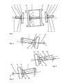
- Figure 1 shows a coupling in cross section with Figures 1a-1c showing components of the Figure 1 coupling
- Figure 2 shows a view of a shaft in the direction looking along the shaft at a coupling element.
- a double tooth coupling is shown by way of example in Figures 1 and 2 .
- the three parts of the double tooth coupling with the end of the first shaft ( Figure 1a ), the middle of the coupling sleeve ( Figure 1b ) on the side to the first shaft and the end of the second shaft ( Figure 1 c) are shown enlarged for better illustration in the three component figures, Figs. 1a, 1b, & 1c .
- the invention is not limited to double tooth couplings, it also be applicable to other rotating machine elements, such as shafts or bearing rings and on couplings with only two or more than three major assemblies.
- a co-rotating disk 21 which is made as a spur gear in a double tooth coupling is mounted on one shaft 1. It is shown that during operation a vertical offset 5 and an angular offset 7 can arise relative to a line of ideal alignment 10.
- an internally toothed region 23 is attached to an end surface of the cylinder so that the teeth of the spur gear 21 engage the teeth of the region 23.
- On the other end surface of the cylinder there is a corresponding internally toothed region 24, the teeth of which engage a co-rotating disk 22 which is mounted on a second shaft 2 and which is likewise made as a spur gear.
- the coupling sleeve 3 can likewise be offset in operation, a parallel offset 4 and an angular offset 9 being shown.
- the axis 28 of the coupling sleeve 3 and its radially running center line 29 are shown in Figure 1 b.
- the second shaft 2 has parallel and angular offsets 6, 8 as shown in Figure 1c .
- the first shaft 1 can be, for example, an engine shaft
- the second shaft 2 can be the shaft of a mill driven by the engine shaft.
- the double tooth coupling is designed to compensate for these offsets and coupling imbalance. Therefore, for curved tooth couplings, the spur gears 21, 22 are equipped with teeth which are provided with a curvature. Thus, movements relative to one another of the spur gears and the shafts connected in this way are enabled.
- At least one sensor which is suitable for recording forces in the radial direction or for recording inclination is mounted on one or more of the three coupling elements, i.e., spur gear 21, spur gear 22 and coupling sleeve 3.
- the three coupling elements i.e., spur gear 21, spur gear 22 and coupling sleeve 3.
- At least two of these sensors are attached on each of these three elements in two differently running radial directions.
- the behavior of each of the three important coupling elements and the behavior of the coupling as a whole can be especially accurately monitored.
- a conclusion can be drawn about the number of damaged teeth and their relative position. Determination of delays in start-up, torque values and/or loading values also becomes possible. Peaks in the signal value or a characteristic, such as torque, can be detected in this way with reference to the respective coupling element.
- the sensors 11, 17 are mounted on the spur gear 21, and in the example of Figures 1 & 2 , the angle enclosed by the measurement directions of the sensors is 90°.
- a third sensor 25, which measures forces in the axial direction or which measures inclination with an axial reference direction in the sensor can also be attached.
- an electronic unit 14 on the respective coupling element which contains, for example, a microprocessor and which monitors one or more of the following functions: supply of electricity to the sensors 11, 17, 25 storage of measured data of the sensors 11, 17, 25 computation of offsets from measured data of the sensors 11, 17, 25 storage of reference data such as, for example, alarm thresholds for forces or offsets computation of orbits from the measured data computation of vibration data from the offsets determination of the state characteristic of the coupling from forces, offsets, orbits, vibration data and operating parameters wireless or wired communication with an electronic unit 15, 16 attached to another coupling element or a higher-order computer or computer network.
- a microprocessor which monitors one or more of the following functions: supply of electricity to the sensors 11, 17, 25 storage of measured data of the sensors 11, 17, 25 computation of offsets from measured data of the sensors 11, 17, 25 storage of reference data such as, for example, alarm thresholds for forces or offsets computation of orbits from the measured data computation of vibration data from the offsets determination of the state characteristic of the coupling from forces, offsets, orbits, vibration data
- the sensors and the electronic unit are supplied with electricity, preferably, via a generator.
- This generator produces electrical energy for example, from the rotary motion of the rotating shaft or from thermal gradients.
- batteries, rechargeable batteries or fuel cells can also be used to provide the required electrical energy.
- a computer device such as a microprocessor in the electronic unit 14, can also be supplied with this electrical energy.
- This computer device in a preferred configuration of the invention, has a memory in which measured values or characteristics computed from the measured values can be stored. This computer device computes the offsets or displacements of the shaft ends from the measurement data of the sensors. It is advantageous that vibration data of the shaft ends or other characteristics are computed from these offsets.
- the sensors 11, 17, 25 in accordance with the invention are designed as sensors for force or acceleration or sensors for sensing gravitation direction.
- an inclinometer is used as a sensor for detecting the direction of the force of gravity.
- MEMS Micro Electromechanical Systems
- the sensors can be radially running accelerometers, for example, piezoelectric or MEMS-based accelerometers.
- accelerometers or strain gauges are used as sensors 11, 17, 25, it is useful to additionally provide at least one inclinometer in order to determine the current rotational position of the respective element 21, 22, 3 or of the respective shaft 1, 2.
- this set of sensors with the associated electronic unit is attached to each of the three elements 21, 22, 3 shown in the figures or to the shafts 1, 2 which bear the spur gears 21, 22.
- this set of sensors with the associated electronic unit is attached to each of the three elements 21, 22, 3 shown in the figures or to the shafts 1, 2 which bear the spur gears 21, 22.
- each of the electronic units 14, 15, 16 exchanges the data determined by it, either with another electronic unit on the same coupling and/or with a higher-order computer or computer network.
- the offset data for each coupling element individually with reference to an ideal line 10, and from them, the state quantities for the coupling as a whole and to make predictions about the service life of the coupling and the expected development of the characteristics which have been determined from the offset data.
- the invention makes it possible to interrogate the current state of the coupling as well as stored data from the past via an operating network, such as a WLAN, or by way of other communications links, such as Bluetooth or self-organizing networks.
- an operating network such as a WLAN
- other communications links such as Bluetooth or self-organizing networks.
- wireless communications paths can be used, but also wired routes, which dictate, for example, the connection of a data collector with a plug-and-socket connection via a communications cable to the electronic unit.
- the module integrated into the coupling automatically communicates that the alarm thresholds or other reference values stored in the electronic unit have been exceeded by way of an existing wireless network or other communications means.
- the measurement data of the sensors are evaluated either in the electronic units or in a computer network supplied with data from these electronic units.
- These measurement data are then stored as a reference. Over time, other measurement data arise which are filed and stored together with the time of the measurement. Instead of measurement data, characteristics determined from these measurement data can also be stored.
- these measurement data and the state characteristics which have been determined from them can then be assigned to the respective operating states of the machine. These operating states include run-up, coasting, continuous operation, the respective operating load and extraordinary loads, such as, for example, exceeding the nominal rpm.
- a suitable method for reducing these amounts of data is use of the rainflow counting method (see, e.g., Downing, S. D., Socie, D. F. (1982). "Simple rainflow counting algorithms”. International Journal of Fatigue, Volume 4, Issue 1, January, 31-40 .).
- other methods can also be used, such as determining average values, envelope curves, cepstra or other characteristics which represent a measure of the operating or load state.
- the invention can be used not only on couplings of slow-running installations, such as mills or rotary tube furnaces, but also on shafts themselves in order to detect their displacements in the sense of torsion and bending.
- slow-running installations such as mills or rotary tube furnaces
- shafts themselves in order to detect their displacements in the sense of torsion and bending.
- the use of the invention is not limited to comparatively slow-running machines, such as the aforementioned mills, but the invention can also be used on faster running or very fast running elements of machines, such as turbines or turbomachinery.
Landscapes
- Physics & Mathematics (AREA)
- Engineering & Computer Science (AREA)
- General Engineering & Computer Science (AREA)
- General Physics & Mathematics (AREA)
- Mechanical Engineering (AREA)
- Acoustics & Sound (AREA)
- Arrangements For Transmission Of Measured Signals (AREA)
Applications Claiming Priority (1)
| Application Number | Priority Date | Filing Date | Title |
|---|---|---|---|
| DE201010006254 DE102010006254A1 (de) | 2010-01-28 | 2010-01-28 | Vorrichtung und Verfahren zum Überwachen rotierender Maschinenelemente |
Publications (2)
| Publication Number | Publication Date |
|---|---|
| EP2351998A2 true EP2351998A2 (de) | 2011-08-03 |
| EP2351998A3 EP2351998A3 (de) | 2014-07-23 |
Family
ID=43989852
Family Applications (1)
| Application Number | Title | Priority Date | Filing Date |
|---|---|---|---|
| EP11152459.1A Withdrawn EP2351998A3 (de) | 2010-01-28 | 2011-01-28 | Vorrichtung und Verfahren zur Überwachung rotierender Maschinenelemente |
Country Status (2)
| Country | Link |
|---|---|
| EP (1) | EP2351998A3 (de) |
| DE (1) | DE102010006254A1 (de) |
Cited By (3)
| Publication number | Priority date | Publication date | Assignee | Title |
|---|---|---|---|---|
| CN108051201A (zh) * | 2018-02-09 | 2018-05-18 | 安徽省特种设备检测院 | 一种防坠安全器检测仪 |
| IT201900006485A1 (it) * | 2019-05-02 | 2020-11-02 | Bondioli & Pavesi S P A | Sistema di verifica delle condizioni d’impiego di un albero cardanico per un attrezzo collegato ad una motrice, e albero cardanico equipaggiato di tale sistema |
| CN117240010A (zh) * | 2023-09-21 | 2023-12-15 | 上海大学 | 一种具有主轴在线监测功能的轴向磁通永磁同步电机 |
Families Citing this family (2)
| Publication number | Priority date | Publication date | Assignee | Title |
|---|---|---|---|---|
| DE102012023201A1 (de) | 2012-11-28 | 2014-05-28 | Prüftechnik Dieter Busch AG | Kupplungsvorrichtung und Verfahren zum Bestimmen der Fehlausrichtung von zwei Wellen |
| EP4030160A1 (de) * | 2021-01-15 | 2022-07-20 | Siemens Aktiengesellschaft | Vorrichtung zur überwachung einer eine erste welle und eine zweite welle kuppelnden wellenkupplung |
Citations (4)
| Publication number | Priority date | Publication date | Assignee | Title |
|---|---|---|---|---|
| DE19506471A1 (de) | 1995-02-24 | 1996-08-29 | Roland Schuehle | Verfahren und Vorrichtung zur elektronischen Bestimmung und Kontrolle der Güte der Ausrichtung aneinandergekuppelter Wellen |
| US5659195A (en) * | 1995-06-08 | 1997-08-19 | The Regents Of The University Of California | CMOS integrated microsensor with a precision measurement circuit |
| US20040024499A1 (en) | 2002-04-23 | 2004-02-05 | Lord Corporation | Aircraft vehicular propulsion system monitoring device and method |
| WO2009011638A1 (en) | 2007-07-18 | 2009-01-22 | A.P. Fixturlaser Ab | System and method for measuring alignment errors of axles |
Family Cites Families (14)
| Publication number | Priority date | Publication date | Assignee | Title |
|---|---|---|---|---|
| GB667217A (en) * | 1949-07-26 | 1952-02-27 | Wilhelm Gustav Stoeckicht | An improved toothed coupling |
| DE1199518B (de) * | 1961-09-21 | 1965-08-26 | Schenck Gmbh Carl | Vorrichtung zum Messen der Unwucht von Rotoren |
| DE2928561A1 (de) * | 1979-07-14 | 1981-01-29 | Rolf Hatlapa | Unwuchtanzeigevorrichtung |
| GB9218068D0 (en) * | 1992-08-25 | 1992-10-14 | Euroflex Transmissions Ltd | Automatic balancing system |
| DE69525629T2 (de) * | 1994-08-31 | 2002-08-29 | Honeywell, Inc. | Selbstversorgte fernstrukturüberwachung |
| US5893892A (en) * | 1994-12-29 | 1999-04-13 | Dana Corporation | Vibration sensing and diagnostic system for vehicle drive train components |
| US5980094A (en) * | 1997-03-28 | 1999-11-09 | Csi Technology, Inc. | Analysis of alignment data |
| US6321602B1 (en) * | 1999-09-28 | 2001-11-27 | Rockwell Science Center, Llc | Condition based monitoring by vibrational analysis |
| US6412345B1 (en) * | 2000-09-29 | 2002-07-02 | Ge Medical Systems Global Technology Company, Llc | Balancing of rotational components of CT imaging equipment |
| DE10304719B4 (de) * | 2003-02-06 | 2005-12-01 | Ifa-Technologies Gmbh | Auswuchteinrichtung für eine einen Hohlraum aufweisende hochzylindrische Kraftfahrzeugantriebswelle und Verfahren zum Betreiben derselben |
| US7398186B2 (en) * | 2005-08-17 | 2008-07-08 | Xtek, Inc. | Data acquisition system for system monitoring |
| DE102008023109A1 (de) * | 2007-09-14 | 2009-03-19 | Prüftechnik Dieter Busch AG | Windenergieanlage und Verfahren zum Betreiben einer Windenergieanlage |
| DE102007058054A1 (de) * | 2007-11-30 | 2009-06-04 | Innovative Windpower Ag | Verfahren zur Regelung der elektrischen Last einer Windenergieanlage |
| WO2009070066A1 (en) * | 2007-11-30 | 2009-06-04 | Volvo Lastvagnar Ab | Method of identifying positions of wheel modules |
-
2010
- 2010-01-28 DE DE201010006254 patent/DE102010006254A1/de not_active Ceased
-
2011
- 2011-01-28 EP EP11152459.1A patent/EP2351998A3/de not_active Withdrawn
Patent Citations (4)
| Publication number | Priority date | Publication date | Assignee | Title |
|---|---|---|---|---|
| DE19506471A1 (de) | 1995-02-24 | 1996-08-29 | Roland Schuehle | Verfahren und Vorrichtung zur elektronischen Bestimmung und Kontrolle der Güte der Ausrichtung aneinandergekuppelter Wellen |
| US5659195A (en) * | 1995-06-08 | 1997-08-19 | The Regents Of The University Of California | CMOS integrated microsensor with a precision measurement circuit |
| US20040024499A1 (en) | 2002-04-23 | 2004-02-05 | Lord Corporation | Aircraft vehicular propulsion system monitoring device and method |
| WO2009011638A1 (en) | 2007-07-18 | 2009-01-22 | A.P. Fixturlaser Ab | System and method for measuring alignment errors of axles |
Non-Patent Citations (1)
| Title |
|---|
| DOWNING, S. D.; SOCIE, D. F.: "Simple rainflow counting algorithms", JOURNAL OF FATIGUE, vol. 4, no. 1, 1982, pages 31 - 40 |
Cited By (8)
| Publication number | Priority date | Publication date | Assignee | Title |
|---|---|---|---|---|
| CN108051201A (zh) * | 2018-02-09 | 2018-05-18 | 安徽省特种设备检测院 | 一种防坠安全器检测仪 |
| IT201900006485A1 (it) * | 2019-05-02 | 2020-11-02 | Bondioli & Pavesi S P A | Sistema di verifica delle condizioni d’impiego di un albero cardanico per un attrezzo collegato ad una motrice, e albero cardanico equipaggiato di tale sistema |
| WO2020222210A1 (en) * | 2019-05-02 | 2020-11-05 | Bondioli & Pavesi S.P.A. | System for checking the conditions of use of a cardan shaft for a tool which is connected to a motor and a cardan shaft provided with such a system |
| CN113785142A (zh) * | 2019-05-02 | 2021-12-10 | 邦迪奥利及帕维西股份公司 | 用于检查连接到马达的工具的万向轴的使用状况的系统和设有这种系统的万向轴 |
| EP4428383A1 (de) * | 2019-05-02 | 2024-09-11 | Bondioli & Pavesi S.p.A. | System zur überprüfung der einsatzbedingungen einer kardanwelle für ein mit einem motor verbundenes werkzeug und kardanwelle mit solch einem system |
| US12123748B2 (en) | 2019-05-02 | 2024-10-22 | Bondioli & Pavesi S.P.A. | System for checking the conditions of use of a cardan shaft for a tool which is connected to a motor and cardan shaft provided with such a system |
| CN117240010A (zh) * | 2023-09-21 | 2023-12-15 | 上海大学 | 一种具有主轴在线监测功能的轴向磁通永磁同步电机 |
| CN117240010B (zh) * | 2023-09-21 | 2024-03-12 | 上海大学 | 一种具有主轴在线监测功能的轴向磁通永磁同步电机 |
Also Published As
| Publication number | Publication date |
|---|---|
| DE102010006254A1 (de) | 2011-08-18 |
| EP2351998A3 (de) | 2014-07-23 |
Similar Documents
| Publication | Publication Date | Title |
|---|---|---|
| US8578772B2 (en) | Device and method for monitoring of rotating machine elements | |
| CN103430004B (zh) | 发电站中的齿轮箱的磨损监控 | |
| EP1760311B1 (de) | Verfahren und Vorrichtung zur betriebsabhängigen Überwachung der Unterteilen einer Windenergieanlage | |
| EP2546518B1 (de) | Abrieberkennungsvorrichtung, damit ausgestatteter windkraftgenerator und abrieberkennungsverfahren | |
| US10298100B2 (en) | Shaft-mounted monitor for monitoring rotating machinery | |
| CN101213436B (zh) | 用于计算轴承寿命的电机接口模块设备 | |
| US9995349B2 (en) | Rotation transmission device and wind power generation device equipped with the same | |
| EP3808971B1 (de) | System zur berührungslosen verschiebungsmessung eines schaufelfusses einer windturbine | |
| JP7027782B2 (ja) | 転がり軸受の異常診断装置 | |
| CN107429818B (zh) | 用于检测行星传动机构的行星架上的变量的测量系统和测量方法 | |
| EP3168463A1 (de) | Verfahren und vorrichtung zur überwachung eines antriebs einer windturbine mit elastischer kupplung | |
| WO2017150190A1 (ja) | トルク計測装置、歯車箱及びトルク計測方法 | |
| EP4428383A1 (de) | System zur überprüfung der einsatzbedingungen einer kardanwelle für ein mit einem motor verbundenes werkzeug und kardanwelle mit solch einem system | |
| US20140318226A1 (en) | Method and calculator unit for determining total damage to at least one rotating component of a drive train | |
| CN216381720U (zh) | 变形评估设备和风力发电机组 | |
| DE102010006254A1 (de) | Vorrichtung und Verfahren zum Überwachen rotierender Maschinenelemente | |
| JP2013087732A (ja) | 風力発電装置の状態監視システム | |
| RU109858U1 (ru) | Стенд определения кпд компенсирующих муфт | |
| JP6561720B2 (ja) | 軸受評価装置 | |
| KR101478078B1 (ko) | 발전소에 있는 기어박스의 마모-모니터링 | |
| CN122041718A (zh) | 一种联轴器对中状态监测装置及监测方法 |
Legal Events
| Date | Code | Title | Description |
|---|---|---|---|
| PUAI | Public reference made under article 153(3) epc to a published international application that has entered the european phase |
Free format text: ORIGINAL CODE: 0009012 |
|
| AK | Designated contracting states |
Kind code of ref document: A2 Designated state(s): AL AT BE BG CH CY CZ DE DK EE ES FI FR GB GR HR HU IE IS IT LI LT LU LV MC MK MT NL NO PL PT RO RS SE SI SK SM TR |
|
| AX | Request for extension of the european patent |
Extension state: BA ME |
|
| PUAL | Search report despatched |
Free format text: ORIGINAL CODE: 0009013 |
|
| AK | Designated contracting states |
Kind code of ref document: A3 Designated state(s): AL AT BE BG CH CY CZ DE DK EE ES FI FR GB GR HR HU IE IS IT LI LT LU LV MC MK MT NL NO PL PT RO RS SE SI SK SM TR |
|
| AX | Request for extension of the european patent |
Extension state: BA ME |
|
| RIC1 | Information provided on ipc code assigned before grant |
Ipc: G01M 13/04 20060101ALI20140619BHEP Ipc: G01M 13/02 20060101ALI20140619BHEP Ipc: F16D 3/18 20060101ALI20140619BHEP Ipc: G01H 1/00 20060101AFI20140619BHEP |
|
| 17P | Request for examination filed |
Effective date: 20141024 |
|
| RBV | Designated contracting states (corrected) |
Designated state(s): AL AT BE BG CH CY CZ DE DK EE ES FI FR GB GR HR HU IE IS IT LI LT LU LV MC MK MT NL NO PL PT RO RS SE SI SK SM TR |
|
| 17Q | First examination report despatched |
Effective date: 20180504 |
|
| STAA | Information on the status of an ep patent application or granted ep patent |
Free format text: STATUS: THE APPLICATION IS DEEMED TO BE WITHDRAWN |
|
| 18D | Application deemed to be withdrawn |
Effective date: 20180915 |