EP2351945A1 - Spring structure - Google Patents
Spring structure Download PDFInfo
- Publication number
- EP2351945A1 EP2351945A1 EP09829196A EP09829196A EP2351945A1 EP 2351945 A1 EP2351945 A1 EP 2351945A1 EP 09829196 A EP09829196 A EP 09829196A EP 09829196 A EP09829196 A EP 09829196A EP 2351945 A1 EP2351945 A1 EP 2351945A1
- Authority
- EP
- European Patent Office
- Prior art keywords
- spring
- compression coil
- coil springs
- spring seat
- end portions
- Prior art date
- Legal status (The legal status is an assumption and is not a legal conclusion. Google has not performed a legal analysis and makes no representation as to the accuracy of the status listed.)
- Withdrawn
Links
- 238000004804 winding Methods 0.000 claims abstract description 49
- 230000006835 compression Effects 0.000 claims description 131
- 238000007906 compression Methods 0.000 claims description 131
- 230000002093 peripheral effect Effects 0.000 claims description 25
- 238000006073 displacement reaction Methods 0.000 claims description 14
- 238000005520 cutting process Methods 0.000 claims description 7
- 238000003780 insertion Methods 0.000 claims description 4
- 230000037431 insertion Effects 0.000 claims description 4
- 239000000725 suspension Substances 0.000 description 22
- 230000000694 effects Effects 0.000 description 12
- 238000000034 method Methods 0.000 description 5
- 230000008569 process Effects 0.000 description 5
- 230000004323 axial length Effects 0.000 description 4
- 239000000853 adhesive Substances 0.000 description 3
- 230000001070 adhesive effect Effects 0.000 description 3
- 230000008878 coupling Effects 0.000 description 3
- 238000010168 coupling process Methods 0.000 description 3
- 238000005859 coupling reaction Methods 0.000 description 3
- 238000010586 diagram Methods 0.000 description 3
- 230000000052 comparative effect Effects 0.000 description 2
- 238000013016 damping Methods 0.000 description 2
- 238000002474 experimental method Methods 0.000 description 2
- 239000000463 material Substances 0.000 description 2
- 230000007246 mechanism Effects 0.000 description 2
- 229910000838 Al alloy Inorganic materials 0.000 description 1
- 230000009471 action Effects 0.000 description 1
- 229910052782 aluminium Inorganic materials 0.000 description 1
- XAGFODPZIPBFFR-UHFFFAOYSA-N aluminium Chemical compound [Al] XAGFODPZIPBFFR-UHFFFAOYSA-N 0.000 description 1
- 238000006243 chemical reaction Methods 0.000 description 1
- 238000004519 manufacturing process Methods 0.000 description 1
- 229910052751 metal Inorganic materials 0.000 description 1
- 239000002184 metal Substances 0.000 description 1
- 239000007769 metal material Substances 0.000 description 1
- 238000003825 pressing Methods 0.000 description 1
- 239000011347 resin Substances 0.000 description 1
- 229920005989 resin Polymers 0.000 description 1
Images















Classifications
-
- F—MECHANICAL ENGINEERING; LIGHTING; HEATING; WEAPONS; BLASTING
- F16—ENGINEERING ELEMENTS AND UNITS; GENERAL MEASURES FOR PRODUCING AND MAINTAINING EFFECTIVE FUNCTIONING OF MACHINES OR INSTALLATIONS; THERMAL INSULATION IN GENERAL
- F16F—SPRINGS; SHOCK-ABSORBERS; MEANS FOR DAMPING VIBRATION
- F16F3/00—Spring units consisting of several springs, e.g. for obtaining a desired spring characteristic
- F16F3/02—Spring units consisting of several springs, e.g. for obtaining a desired spring characteristic with springs made of steel or of other material having low internal friction
- F16F3/04—Spring units consisting of several springs, e.g. for obtaining a desired spring characteristic with springs made of steel or of other material having low internal friction composed only of wound springs
-
- B—PERFORMING OPERATIONS; TRANSPORTING
- B60—VEHICLES IN GENERAL
- B60G—VEHICLE SUSPENSION ARRANGEMENTS
- B60G11/00—Resilient suspensions characterised by arrangement, location or kind of springs
- B60G11/14—Resilient suspensions characterised by arrangement, location or kind of springs having helical, spiral or coil springs only
-
- B—PERFORMING OPERATIONS; TRANSPORTING
- B60—VEHICLES IN GENERAL
- B60G—VEHICLE SUSPENSION ARRANGEMENTS
- B60G15/00—Resilient suspensions characterised by arrangement, location or type of combined spring and vibration damper, e.g. telescopic type
- B60G15/02—Resilient suspensions characterised by arrangement, location or type of combined spring and vibration damper, e.g. telescopic type having mechanical spring
- B60G15/06—Resilient suspensions characterised by arrangement, location or type of combined spring and vibration damper, e.g. telescopic type having mechanical spring and fluid damper
- B60G15/062—Resilient suspensions characterised by arrangement, location or type of combined spring and vibration damper, e.g. telescopic type having mechanical spring and fluid damper the spring being arranged around the damper
- B60G15/065—Resilient suspensions characterised by arrangement, location or type of combined spring and vibration damper, e.g. telescopic type having mechanical spring and fluid damper the spring being arranged around the damper characterised by the use of a combination of springs
-
- F—MECHANICAL ENGINEERING; LIGHTING; HEATING; WEAPONS; BLASTING
- F16—ENGINEERING ELEMENTS AND UNITS; GENERAL MEASURES FOR PRODUCING AND MAINTAINING EFFECTIVE FUNCTIONING OF MACHINES OR INSTALLATIONS; THERMAL INSULATION IN GENERAL
- F16F—SPRINGS; SHOCK-ABSORBERS; MEANS FOR DAMPING VIBRATION
- F16F1/00—Springs
- F16F1/02—Springs made of steel or other material having low internal friction; Wound, torsion, leaf, cup, ring or the like springs, the material of the spring not being relevant
- F16F1/04—Wound springs
- F16F1/12—Attachments or mountings
-
- B—PERFORMING OPERATIONS; TRANSPORTING
- B60—VEHICLES IN GENERAL
- B60G—VEHICLE SUSPENSION ARRANGEMENTS
- B60G2202/00—Indexing codes relating to the type of spring, damper or actuator
- B60G2202/10—Type of spring
- B60G2202/12—Wound spring
-
- B—PERFORMING OPERATIONS; TRANSPORTING
- B60—VEHICLES IN GENERAL
- B60G—VEHICLE SUSPENSION ARRANGEMENTS
- B60G2204/00—Indexing codes related to suspensions per se or to auxiliary parts
- B60G2204/10—Mounting of suspension elements
- B60G2204/12—Mounting of springs or dampers
- B60G2204/124—Mounting of coil springs
-
- B—PERFORMING OPERATIONS; TRANSPORTING
- B60—VEHICLES IN GENERAL
- B60G—VEHICLE SUSPENSION ARRANGEMENTS
- B60G2206/00—Indexing codes related to the manufacturing of suspensions: constructional features, the materials used, procedures or tools
- B60G2206/01—Constructional features of suspension elements, e.g. arms, dampers, springs
- B60G2206/40—Constructional features of dampers and/or springs
- B60G2206/42—Springs
Definitions
- the present invention relates to a spring structure for various use, such as a suspension spring of an automobile, and a spring to be assembled to an intake valve or an exhaust valve of an engine.
- an automobile, a motorcycle, etc. includes a suspension for rockably coupling a wheel and a vehicle body together through an arm, a link, a rod, or the like.
- the suspension prevents impact and vibration of the wheel from being transmitted to the vehicle body by a damper provided with a spring structure.
- a suspension spring spring structure
- JP 10-26166 A two compression coil springs having the same winding direction are arranged in series, and end portions of the compression coil springs, which face to each other, are threadably fixed to and overlap each other.
- the suspension spring is placed between a body-side tube supported on the vehicle body and an axle-side tube for supporting an axle.
- the suspension spring is provided with a spring constant adjuster capable of changing an overlapping length of the compression coil springs.
- both ends of the suspension spring are displaced in a twisting direction and receive a torsional force. Consequently, an excess frictional force may be generated at a contacting portion between the one end of the suspension spring and the vehicle body or a contacting portion between the other end of the suspension spring and the wheel side, or the torsional force may act on the suspension, which may have an influence on performance of the damper and the suspension.
- springs for various use other than for the suspension spring have similar problems.
- the present invention has been made to solve the above-mentioned problems, and has an object to provide a spring structure, which prevents the discrepancy in the twisting direction and the torsional force from occurring at the ends of the compression coil spring along with expansion and shrinkage, and solves a new problem involved with the countermeasures therefor, to thereby improve performance.
- a spring structure according to the present invention has the following structural characteristic.
- the spring structure which is mounted between a base and a moving section which advances to/retreats from the base, includes two compression coil springs different in winding directions, in which one end portions of the two compression coil springs are respectively supported on the base and the moving section directly or through a predetermined member, the other end portions of the two compression coil springs are respectively abutted on front and back surfaces of a spring seat interposed between the other end portions in a state where the other end portions are shifted, with reference to start points of effective windings of the two compression coil springs or end portions of element wires of the two compression coil springs, from each other in position in a circumferential direction around an axis of the two compression coil springs, the two compression coil springs are coaxially arranged through the spring seat, and the spring seat is movable in an axial direction of the two compression coil springs and in the circumferential direction around the axis
- the two compression coil springs different in the winding directions are arranged in series through the spring seat so as to be coaxially positioned.
- the spring seat is movable in the axial direction and in the circumferential direction around the axis of the two compression coil springs, and hence the spring seat freely moves on reception of a force from the two compression coil springs.
- the two compression coil springs have the different winding directions, and hence, at the time of expansion and shrinkage, the end portions toward the spring seat of the two compression coil springs are turned (rotated) in the same direction, to thereby turn the spring seat in the circumferential direction around the axis of the compression coil springs.
- the other end portions of the two compression coil springs which face to each other through the spring seat, are shifted from each other in position in the circumferential direction around the axis of the two compression coil springs with reference to the start points of the effective windings of the two compression coil springs or the end portions of the element wires of the two compression coil springs.
- an auxiliary spring, a seat member or the like is provided as the predetermined member between the one end portion of each of the two compression coil springs and the base or the moving section.
- the spring structure according to the present invention has another following structural characteristic. Specifically, the shift, provided in the circumferential direction around the axis of the two compression coil springs, between the other end portions of the two compression coil springs abutting on the spring seat is set within a range of 180 ⁇ 45 degrees with reference to the start points of the effective windings or the end portions of the element wires by a degree.
- the start point of the effective winding defined in the above structure corresponds to a point at which an end-side portion of each compression coil spring is separated from a member abutted on the end-side portion, or a point at which the effective winding of the compression coil spring starts from the end turn portion of the compression coil spring, that is, a boundary between a contact portion and a non-contact portion each of which is defined between the end-side portion of the compression coil spring and the abutted member, or a boundary between the effective winding and the end turnportionof the compression coil spring.
- the end portion of the element wire corresponds to a distal end surface or a distal end of the compression coil spring.
- the shift, provided in the circumferential direction around the axis of the two compression coil springs, between the other end portions of the two compression coil springs abutting on the spring seat is set with reference to the start points of the effective windings or the end portions of the element wires by a degree, and thus it is possible to precisely set the shift amount of the other end portions. Consequently, the more preferred spring structure can be obtained.
- the most preferred shift amount in this structure is 180 degrees of the shift between the end portions of the element wires or between the start points of the effective windings in the other end portions of the two compression coil springs, the shift being provided in the circumferential direction around the axis of the compression coil springs.
- the spring structure according to the present invention has still another following structural characteristic. Specifically, the both front and back surfaces of the spring seat, on which the other end portions of the two compression coil springs abut, are formed into flat surfaces, and the other end portions of the two compression coil springs which abut on the spring seat are formed into flat surfaces orthogonal to the axis of the two compression coil springs. With this, the two compression coil springs can be arranged in right coaxial manner through the spring seat, and hence performance of the spring structure can be further improved. Further, in this structure, engagement sections, positioning sections, and the like, which are engaged together, can be provided between the end portions of the two compression coil springs and the both front and back surfaces of the spring seat. Thus, the end portions of the compression coil springs can be positioned at appropriate positions of the spring seat.
- the spring structure according to the present invention has still another following structural characteristic.
- the spring seat includes: an abutting plate portion on which the other end portions of the two compression coil springs abut; and a coaxially holding portion, which coaxially holds the two compression coil springs, provided to both front and back surfaces of the abutting plate portion.
- the spring seat in this structure, spring seats with various shapes can be used.
- the spring seat may include an abutting plate portion constituted by an annular or circular plate portion, and a coaxially holding portion constituted by a tubular portion provided at an outer periphery of the abutting plate portion.
- the spring seat may include an abutting plate portion constituted by an annular plate portion, and a coaxially holding portion constituted by a tubular portion provided at an inner circumference of the annular abutting plate portion.
- the coaxially holding portion constituted by the tubular portion is provided at the outer periphery of the annular or circular abutting plate portion, the end portions of the two compression coil springs can be inserted into the tubular portion respectively from above and below the tubular portion, and thus the two compression coil springs can be coaxially holed. Further, the tubular portion can protect the end portions toward the spring seat of the two compression coil springs.
- the end portions of the two compression coil springs are positioned at the outer periphery of the tubular portion respectively from above and below the tubular portion, and thus the two compression coil springs can be coaxially held. Further, according to this way, it is possible to prevent extraneous material from being accumulated inside the tubularportion. Because, as described above, the other end portions of the two compression coil springs are shifted in position in the circumferential direction around the axis of the two compression coil springs and the coaxially holding portion is provided to the spring seat, the two compression coil springs can be more reliably held coaxially.
- the spring seat may include the abutting plate portion constituted by an annular plate portion, a tubular portion protruding from an inner circumferential portion of the annular abutting plate portion in one direction, and a tubular portion protruding from an outer peripheral portion of the annular abutting plate portion in the other direction.
- the coaxially holding portion provided to the both front and back surfaces of the abutting plate portion may include a coaxially holding portion protruding from an outer peripheral edge portion and an inner circumferential edge portion of the abutting plate portion toward the both front side and back side of the abutting plate portion. Further, the coaxially holding portion may not be tubular. The coaxially holding portion only needs to hold the two compression coil springs coaxially.
- the spring structure according to the present invention has still another following structural characteristic. Specifically, the both front and back surfaces of the spring seat, on which the other end portions of the two compression coil springs are disposed, have engaging protrusions formed thereon which allow the end portions of the element wires of the two compression coil springs to abut to the engaging protrusions.
- the spring structure according to the present invention has still another following structural characteristic. Specifically, the other end portions of the two compression coil springs abutting on the spring seat are provided with engaged recesses, and the both front and back surfaces of the spring seat, on which the other end portions of the two compression coil springs abut, have engaging protrusions formed thereon which allow the engaged recesses of the two compression coil springs to be engaged to engaging protrusions.
- the end portions in this structure is defined as distal end portions of the compression coil springs and vicinities of the distal end portions, and thus the scope of the end portions include end surfaces of the compression coil springs.
- the spring structure according to the present invention has still another following structural characteristic.
- the other end portions of the two compression coil springs abutting on the spring seat have shapes made just by cutting, and the both front and back surfaces of the spring seat, on which the end portions of the two compression coil springs abut, have engagement recesses formed thereon which allow the end portions of the element wires of the two compression coil springs to be engaged to the engagement recesses.
- the compression coil springs assembled to the spring structure have the end portions formed into end surfaces having shapes made just by cutting and not provided with processing for forming the end portions into flat surfaces orthogonal to the axial direction. And hence, it is possible to reduce manufacturing cost.
- the engagement recess in this structure preferably includes a recess having a surface capable of supporting at least part in the end surface of the compression coil spring and the peripheral surface of a vicinity of the end portion of the compression coil spring, to thereby prevent the end portion of the compression coil spring from being misaligned with respect to the spring seat.
- portions of the spring seat on which the other end portions of the two compression coil springs abut are respectively provided with recesses shifted in position in the circumferential direction, and the other end portions of the two compression coil springs abutting on the spring seat are positioned in the recesses, respectively.
- the end portions in this structure are also defined as the distal end portions of the compression coil springs and vicinities of the distal end portions. With this, it is possible to reduce a length of the spring structure in the axial direction.
- the spring structure according to the present invention has still another following structural characteristic.
- the two compression coil springs different in the winding directions includes compression coil springs having different diameters. With this, in a case where a space for placing the spring structure is narrow, the compression coil spring with a smaller diameter can be arranged in the narrow space, and thus the spring structure can be mounted.
- the spring structure according to the present invention has still another following structural characteristic.
- the two compression coil springs different in the winding directions include compression coil springs having different diameters, and the portions of the spring seat on which the other end portions of the two compression coil springs abut are formed into such shape that the portions of the spring seat are positioned on different levels in the axial direction so that the two compression coil springs partially overlap each other in the axial direction.
- the spring structure according to the present invention has still another following structural characteristic.
- the two compression coil springs different in the winding directions are substantially same in characteristic shown when the two compression coil springs shrink and defining a torsion angle in the twisting direction with respect to a displacement amount of the spring.
- the torsion angles caused therein are substantially equal.
- the torsional force generated in the two compression coil springs is completely released by turning of the spring seat.
- a telescopic shaft includes an inner shaft portion which includes a spring seat portion on an outer peripheral portion of the inner shaft portion, and an outer shaft portion which includes a spring seat portion on an outer peripheral portion of the outer shaft portion and is assembled to the inner shaft portion to be movable in the axial direction, and one of the inner shaft portion and the outer shaft portion of the telescopic shaft serves as the base, and the other one of the inner shaft portion and the outer shaft portion serves as the moving section so that the spring structure is disposed between the spring seat portions on the outer periphery of the telescopic shaft.
- the telescopic shaft may employ a damper for a vehicle, or a mechanism including intake and exhaust valves of an engine and valve guides for slidably supporting the intake and exhaust valves.
- an insertion hole may be formed in a center of the spring seat, and the telescopic shaft may pass through the insertion hole of the spring seat.
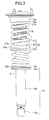
- FIG. 1 illustrates a spring structure 20 according to this embodiment
- FIG. 2 illustrates a spring structure 20a
- the spring structure 20 is arranged between the body 11 of an automobile and a front wheel FL arranged on each of a left side and the right side of the front portion of the body 11.
- the spring structure 20a is arranged between the body 11 of the automobile and a rear wheel RL arranged on each of the left side and the right side of the rear portion of the body 11.
- Each of the spring structure 20 and the spring structure 20a constitutes a part of a suspension.
- the suspension prevents impact and vibration from being transmitted to the body 11 from the front wheel FL, the front wheel FR, the rear wheel RL, or the rear wheel RR.
- a front part of the suspension is provided with a damper D serving as a telescopic shaft of the present invention.
- the damper D includes an inner shaft portion 13 (see FIG. 4 ) serving as a base coupled to the body 11, and a tubular outer shaft portion 14 (see FIG. 3 and FIG. 4 ) serving as a moving section coupled to each of the front wheel FL and the front wheel FR.
- the spring structure 20 is placed on an outer periphery of the damper D.
- the damper D may be turned upside down, the outer shaft portion 14 as the base may be arranged toward the body 11, and the inner shaft portion 13 as the moving section may be arranged toward the front wheel FL and the front wheel FR.
- the inner shaft portion 13 includes a fixed portion 13a fixed to the body 11, a piston rod 13b extending downward from a center portion of the fixed portion 13a through a rubber mount 13d, and a piston 13c attached to an outer periphery of a lower end of the piston rod 13b. Further, an upper spring seat portion 15 having an annular shape and a flat surface is formed on a lower surface of a lower portion of the fixed portion 13a, the lower portion having a small diameter. A cylindrical portion 15a for locking protrudes downward from the inner circumferential edge portion of the upper spring seat portion 15, having a short length in the axial direction.
- the outer shaft portion 14 includes: a coupling portion 14a coupled to an arm 16 arranged toward the front wheel FL and FR; a cylinder 14b which is formed into a cylindrical body with a closed bottom and has the bottom welded to the coupling portion 14a; a piston rod guide 14d closing an upper end opening of the cylinder 14b and supporting the piston rod 13b so as to allow the piston rod 13b to slide; and a spring seat portion 14c positioned slightly higher than a center in an up-and-down direction on an outer peripheral surface of the cylinder 14b.
- the spring seat portion 14c includes an annular lower spring seat portion 17 having an upper surface as a flat surface, and a cylindrical portion 17a for locking which extends upward along the cylinder 14b from an inner circumferential edge portion of the lower spring seat portion 17 and has a short length in the axial direction.
- An inner circumferential surface of the cylindrical portion 17a is fixed to the outer peripheral surface of the cylinder 14b through a lock ring 17b.
- the piston 13c of the inner shaft portion 13 is allowed to slide in fluid-tight contact with an inner circumferential surface of the cylinder 14b of the outer shaft portion 14.
- oil chambers i.e., two upper and lower chambers defined by the piston 13c are formed inside the cylinder 14b.
- the oil chambers are adjacent to a high-pressure gas chamber, and are always under pressure by a free piston.
- the piston 13c has well-known paired flow passages extending between upper and lower surfaces of the piston 13c. Through the paired flow passages, oil moves between the oil chambers provided above and below the piston 13c, and thus a damping force is generated in the damper D.
- a bellows-shaped cover member 18 formed of an elastic member is fixed to the upper spring seat portion 15 of the inner shaft portion 13, and a lower end portion thereof extends, in a free state, to the vicinity of an upper end portion at the outer periphery of the cylinder 14b.
- This configuration prevents mud and the like from adhering to the piston rod 13b.
- a seat 19a is molded integrally with an upper end of the cover member 18 and sandwiched between a clockwise spring 21 and the upper spring seat portion 15.
- the spring structure 20 includes the clockwise spring 21 arranged on an upper side between the upper spring seat portion 15 and the lower spring seat portion 17, a counterclockwise spring 22 arranged on a lower side therebetween, and a spring seat 23 arranged between the clockwise spring 21 and the counterclockwise spring 22.
- Springs having the same diameter, length in the axial direction, spring constant, and the like serve as the clockwise spring 21 and the counterclockwise spring 22. That is, the clockwise spring 21 and the counterclockwise spring 22 have the same configuration except for a difference in winding directions. Therefore, the clockwise spring 21 and the counterclockwise spring 22 have the same characteristic defining a torsion angle in the twisting direction (the characteristic is defined as relation between the torsion angle and the displacement amount).
- both end portions of the clockwise spring 21 and both end portions of the counterclockwise spring 22 are processed to be formed into flat surfaces orthogonal to axial direction of the springs.
- the clockwise spring 21 includes, at both ends thereof, end turn portions 21a, 21b respectively which are wound one turn.
- the counterclockwise spring 22 includes, at both ends thereof, end turn portions 22a, 22b respectively which are wound one turn.
- Each of the end turn portions 21a, 21b is defined as a one turn along a line making a loop that starts from the end portion A (see FIG. 4 ) of the element wire of the spring and then comes back to the end portion A of the element wire to be adjacent to a close contact portion B, and therefore each of the end turn portions 21a, 21b does not function as a spring.
- the middle portion between the end turn portions 21a, 21b at the both ends of the spring and the middle portion between the end turn portions 22a, 22b is an effective winding portion functioning as a spring.
- the start point of the effective winding portion corresponds to the above-mentioned close contact portion B.
- the start point of the effective winding is also denoted by "B".
- the clockwise spring 21 are formed such that the start points B of the effective winding on the both end sides of the clockwise spring 21 are shifted by 180 degrees in a circumferential direction around an axis of the clockwise spring 21, and the counterclockwise spring 22 are formed such that the start points B of the effective winding on the both end sides of the counterclockwise spring 22 are shifted by 180 degrees in a circumferential direction around an axis of the counterclockwise spring 22.
- the spring seat 23 is formed of a molded body made of a metal material such as aluminum, and is shaped such that a cylindrical tubular portion 23b serving as a coaxially holding portion in the present invention is coupled at an outer periphery of an annular abutting plate portion 23a.
- the abutting plate portion 23a is formed into an annular flat plate portion which has an inner diameter slightly larger than an outer diameter of the cover member 18 and has an outer diameter equal to or slightly larger than an outer diameter of the clockwise spring 21 and an outer diameter of the counterclockwise spring 22.
- a flat surface portion at a lower end of the clockwise spring 21 (part of the end turn portion 21b) abuts on an upper surface of the abutting plate portion 23a, and a flat surface portion at an upper end of the counterclockwise spring 22 (part of the end turn portion 22a) abuts on a lower surface of the abutting plate portion 23a.
- the abutting plate portion 23a has upper and lower surfaces formed into flat surfaces, and is formed to have a constant thickness. Under a state of being orthogonal to the axial direction of the clockwise spring 21 and the counterclockwise spring 22, the abutting plate portion 23a abuts on the flat surface at the end of the clockwise spring 21, the flat surface at the end of the counterclockwise spring 22, and the end turn portions 21b, 22a respectively corresponding to the flat surfaces at the ends thereof.
- the tubular portion 23b is arranged such that its axial direction is along the up-and-down direction.
- tubular portion 23b is coupled to the abutting plate portion 23a such that the center portion in the up-and-down direction of the inner circumferential surface of the tubular portion 23b surrounds the outer periphery of the abutting plate portion 23a.
- the lower end portion of the clockwise spring 21 is inserted into an upper interior of the tubular portion 23b, and the upper end portion of the counterclockwise spring 22 is inserted into a lower interior of the tubular portion 23b.
- the clockwise spring 21 and the counterclockwise spring 22 are held so as to be coaxial with each other.
- the spring seat 23 is sandwiched by the clockwise spring 21 and the counterclockwise spring 22 and is changed in position in accordance with forces applied from the clockwise spring 21 and the counterclockwise spring 22.
- the clockwise spring 21 and the counterclockwise spring 22 expand and shrink, the respective springs 21, 22 are twisted in a shrink process such that coils of the springs 21, 22 are loosened, and are twisted in an expansion process such that the coils thereof are fastened.
- the end portion toward the spring seat 23 of the clockwise spring 21 and that of the counterclockwise spring 22 have the same rotating (twisting) direction, to thereby turn the spring seat 23 in the circumferential direction around the axis of the spring.
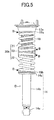
- the start point B of the effective winding at the lower end of the clockwise spring 21 and the start point B of the effective winding at the upper end of the counterclockwise spring 22 are shifted by 180 degrees in position in the circumferential direction around the axis of the clockwise spring 21 or the counterclockwise spring 22.
- the clockwise spring 21 and the counterclockwise spring 22 are arranged such that the start point B of the effective winding at the upper end of the clockwise spring 21 and the start point B of the effective winding at the lower end of the counterclockwise spring 22 are shifted by 180 degrees in the circumferential direction around the axis of the clockwise spring 21 or the counterclockwise spring 22.
- this point is not essential to the present invention.
- the start point B of effective winding at the lower end of the clockwise spring 21 and the start point B of effective winding at the upper end of the counterclockwise spring 22 are shifted by 180 degrees in the circumferential direction around the axis of the spring.
- Black arrows illustrated in FIG. 7 also indicate the position of the start point B of effective winding of the clockwise spring 21 and that of the counterclockwise spring 22, respectively.
- the clockwise spring 21 and the counterclockwise spring 22 shrink, the large forces F are applied to the positions indicated by the black arrows.
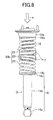
- the white arrow "a" illustrated in FIG. 8 When a force is applied in the direction of the white arrow "a" illustrated in FIG. 8 and then the spring structure 20 shrinks, the large forces F are applied to both sides relative to the axis of the spring structure 20b. Consequently, as illustrated in FIG. 8 , the spring structure 20 shrinks straight in the axial direction. In this case, only the spring seat 23 is slightly inclined relative to the axial direction of the clockwise spring 21 and the counterclockwise spring 22.
- the annular seat 19a molded integrally with the cover member 18 is placed between the upper spring seat portion 15 and the upper end portion of the clockwise spring 21.
- an annular elastic seat 19b is placed between the lower spring seat portion 17 and the lower end portion of the counterclockwise spring 22.
- Each of the seat 19a and the elastic seat 19b is a well-known member for preventing self-excited vibration of the spring from being transmitted to the body 11.
- the seat is not limited thereto, and may be placed between the abutting plate portion 23a and the clockwise spring 21 or between the abutting plate portion 23a and the counterclockwise spring 22.
- the spring structure 20 As described above, even when the front wheels FL, FR and the like vibrate or receive impact due to a reaction force from a road surface during vehicle running, the vibration and impact are prevented from being transmitted to the vehicle body owing to action of the spring structure 20. Further, the damping force is generated owing to actuation of the damper D, and thereby the running state of the vehicle can be maintained in a preferable state. Further, in the spring structure 20 according to this embodiment, the clockwise spring 21 and the counterclockwise spring 22 different in the winding directions are coaxially arranged through the spring seat 23.
- the spring seat 23 is not fixed, but supported only by being sandwiched between the clockwise spring 21 and the counterclockwise spring 22, and hence the spring seat 23 is movable in the axial direction of the spring structure 20 and a circumferential direction around the axis of the spring structure.
- both the upper and lower surfaces of the abutting plate portion 23a of the spring seat 23 are formed as flat surfaces, and the end portions of the clockwise spring 21 and the end portions of the counterclockwise spring 22 are formed as flat surfaces orthogonal to the axial direction of the spring structure 20. Therefore, the clockwise spring 21 and the counterclockwise spring 22 can be arranged in a right coaxial manner through the spring seat 23, and thereby performance of the spring structure 20 can be further improved.
- start point B of the effective winding at the lower end of the clockwise spring 21 and the start point B of the effective winding at the upper end of the counterclockwise spring 22 are shifted by 180 degrees in the circumferential direction around the axis of the spring, and hence, when the spring structure 20 shrinks, the boundary portion between the clockwise spring 21 and the counterclockwise spring 22 is prevented from being displaced together with the spring seat 23 in a direction orthogonal to the axial direction of the springs. In this way, the clockwise spring 21 and the counterclockwise spring 22 can be maintained to be straight arranged.
- the end portion toward the spring seat 23 of the clockwise spring 21 and that of the counterclockwise spring 22 are inserted, from above and below, into the inside of the tubular portion 23b of the spring seat 23.
- the clockwise spring 21 and the counterclockwise spring 22 can be coaxially held, and the end portion toward the spring seat 23 of the clockwise spring 21 and that of the counterclockwise spring 22 can be protected.
- coaxial alignment of the springs 21, 22 can be further ensured, and the spring seat 23 can be united with both of the springs 21, 22. Consequently, preferable assemblability can be achieved.
- the clockwise spring 21 and the counterclockwise spring 22 have substantially the same characteristic for the torsion angle in the rotating direction with respect to the displacement amount of each of the springs, and hence substantially equal torsion angles occur in the clockwise spring 21 and the counterclockwise spring 22 at the time of their expansion and shrink.
- the torsional forces generated in the clockwise spring 21 and the counterclockwise spring 22 completely released in the rotating direction of the spring seat 23, and hence discrepancy in the rotating direction and forces in the rotating direction can be prevented from occurring at both ends of the spring structure 20.
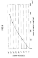
- this characteristic can be shown by a relation between a torsion angle (degree) and a displacement amount (mm) of the coil spring, and FIG. 9 shows the relation between the torsion angle and the displacement amount when using a coil spring with an axial length of 300 mm, an inner diameter of 70 mm, a element wire diameter of 11.5 mm, and the number of the effective winding of 8.0.
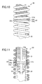
- FIG. 10 and FIG. 11 illustrate a main part of a spring structure 30 according to a second embodiment of the present invention.
- a spring seat 33 includes an annular abutting plate portion 33a and a cylindrical tubular portion 33b defined as the coaxially holding port ion in the present invention, the tubular portion 33b being coupled to the inner circumferential edge portion of the abutting plate portion 33a.
- the tubular portion 33b is arranged such that its axial direction is along the up-and-down direction, and is coupled to the abutting plate portion 33a under a state in which the inner circumference of the abutting plate portion 33a surrounds a center portion in the up-and-down direction of the outer peripheral surface of the tubular portion 33b.
- a lower end portion of a clockwise spring 31 abuts on the upper surface of the abutting plate portion 33a
- an upper end portion of a counterclockwise spring 32 abuts on the lower surface of the abutting plate portion 33a. Further, the lower end portion of the clockwise spring 31 and the upper end portion of the counterclockwise spring 32 are engaged with the outer peripheral surface of the tubular portion 33b.
- spring structure 30 Other configurations of the spring structure 30 are the same as those of the above-mentioned spring structure 20. Therefore, the same components are denoted by the same reference symbols, and description thereof is omitted. According to the spring structure 30, the lower end portion of the clockwise spring 31 and the upper end portion of the counterclockwise spring 32 are engaged with the outer periphery of the tubular portion 33b, and thereby the clockwise spring 31 and the counterclockwise spring 32 can be coaxially held. Further, it is possible to prevent extraneous materials such as mud from being accumulated inside the tubular portion 33b. Other functions and effects of the spring structure 30 are the same as those of the above-mentioned spring structure 20.
- both of the springs 31, 32 may be bonded to the spring seat 33.
- the portions of the springs 31, 32, on which the spring seat 33 abuts, may be preferably polished so as to be flat surfaces.
- FIG. 12 and FIG. 13 illustrate a main part of a spring structure 30a according to Modified Example 1 for the above-mentioned spring structure 30.
- a spring seat 34 includes an abutting plate portion 34a, an engaging protrusion 34b, and an engaging protrusion 34c.
- the engaging protrusion 34b is formed on a predetermined portion of the abutting plate portion 34a, and protrudes from the upper surface of the abutting plate portion 34a.
- the engaging protrusion 34c is formed to be spaced apart by 180 degrees from the portion on which the engaging protrusion 34b is formed in the abutting plate portion 34a, and protrudes from the lower surface of the abutting plate portion 34a.
- an end portion of an element wire of an end turn portion 31b formed at a lower end of a clockwise spring 31a forms an engaged surface 31c that is formed as substantially vertical plane.
- An end portion of an element wire of an end turn portion 32b formed at an upper end of a counterclockwise spring 32a forms an engaged surface 32c that is formed as substantially vertical plane.
- the clockwise spring 31a is arranged on the upper side of the abutting plate portion 34a under a state in which the engaged surface 31c is abutted on the engaging protrusion 34b
- the counterclockwise spring 32a is arranged on the lower side of the abutting plate portion 34a under a state in which the engaged surface 32c is abutted on the engaging protrusion 34c.
- Other configurations of the spring structure 30a are the same as those of the above-mentioned spring structure 30. Therefore, the same components are denoted by the same reference symbols, and description thereof is omitted.
- the lower end portion of the clockwise spring 31a and the upper end portion of the counterclockwise spring 32a can be positioned at appropriate positions on the spring seat 34 while being shifted precisely by 180 degrees.
- Other functions and effects of the spring structure 30a are the same as those of the above-mentioned spring structure 30.
- the portions of the springs 31a, 32a, on which the spring seat 34 abuts may be polished to form flat surfaces, and both of the springs 31a, 32a may be bonded to the spring seat 34.
- FIG. 14 illustrates a main part of a spring structure 30b according to Modified Example 2 for the above-mentioned spring structure 30.
- an engaged recess 35b is formed in a lower surface of a distal end of an end turn portion 35a formed at a lower end of a clockwise spring 35
- an engaged recess 36b is formed in a upper surface of a distal end of an end turn portion 36a formed at an upper end of a counterclockwise spring 36.
- Other configurations of the spring structure 30b are the same as those of the above-mentioned spring structure 30a. Therefore, the same components are denoted by the same reference symbols, and description thereof is omitted.
- the clockwise spring 35 is placed on the upper side of the abutting plate portion 34a under a state in which the engaged recess 35b is engaged on the engaging protrusion 34b.
- the counterclockwise spring 36 is placed on the lower side of the abutting plate portion 34a under a state in which the engaged recess 36b is engaged on the engaging protrusion 34c.
- the lower end portion of the clockwise spring 35 and the upper end portion of the counterclockwise spring 36 can be positioned at appropriate positions on the spring seat 34 while being shifted precisely by 180 degrees.
- Other functions and effects of the spring structure 30b are the same as those of the above-mentioned spring structure 30.
- the portion of the springs 35, 36, on which the spring seat 34 abuts may be polished to form flat surfaces, and both of the springs 35, 36 may be bonded to the spring seat 34.
- the spring structure 20 according to the first embodiment may be provided with the positioning section including the engaging protrusions 34b, 34c and the engaged surfaces 31c, 32c provided to the above-mentioned spring structure 30a according to Modified Example 1, or the engagement section including the engaging protrusions 34b, 34c and the engaged recesses 35b, 36b provided to the spring structure 30b according to Modified Example 2.
- FIG. 16 and FIG. 17 illustrate a main part of a spring structure 40 according to a third embodiment of the present invention.
- a spring seat 43 is formed by pressing a sheet metal, and has a configuration in which a cylindrical tubular portion 43b is coupledto an inner circumference of an annular abutting plate portion 43a, and a cylindrical tubular portion 43c is coupled to an outer periphery of the annular abutting plate portion 43a.
- the tubular portion 43b and the tubular portion 43c form the coaxially holding portion according to the present invention.
- the tubular portion 43b is arranged such that its axial direction is along the up-and-down direction, and is coupled to the abutting plate portion 43a under a state in which the inner circumference of the abutting plate portion 43a surrounds the lower end portion of the tubular portion 43b.
- the tubular portion 43c is arranged such that its axial direction is along the up-and-down direction, and is coupled to the abutting plate portion 43a under a state in which the outer periphery of the abutting plate portion 43a is along the upper end portion of the tubular portion 43c.
- a clockwise spring 41 abuts on the upper surface of the abutting plate portion 43a, and the upper end portion of a counterclockwise spring 42 abuts on the lower surface of the abutting plate portion 43a. Further, the lower end portion of the clockwise spring 41 is engaged with the outer peripheral surface of the tubular portion 43b, and the upper end portion of the counterclockwise spring 42 is engaged with the inner circumferential surface of the tubular portion 43c.
- Other configurations of the spring structure 40 are the same as those of the above-mentioned spring structure 20. Therefore, the same components are denoted by the same reference symbols, and description thereof is omitted.
- the lower end portion of the clockwise spring 41 is engaged with the outer peripheral surface of the tubular portion 43b, and the upper end portion of the counterclockwise spring 42 is engaged with the inner circumferential surface of the tubular portion 43c. Consequently, the clockwise spring 41 and the counterclockwise spring 42 can be coaxially held.
- Other functions and effects of the spring structure 40 are the same as those of the above-mentioned spring structure 20.
- portions of the springs 41, 42, on which the spring seat 43 abuts may be polished to form flat surfaces, and both of the springs 41, 42 may be bonded to the spring seat 43.
- FIG. 18 and FIG. 19 illustrate a main part of a spring structure 50 according to a fourth embodiment of the present invention.
- a lower end portion of a clockwise spring 51 and an upper end portion of a counterclockwise spring 52 are not provided with the processing and thus have a shape made just by cutting.
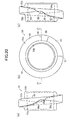
- a spring seat 53 includes an annular abutting plate portion 53a and a cylindrical tubular portion 53b illustrated in FIGS. 20 and FIG. 21 .
- FIG. 20 (b) is a plan view of the spring seat 53
- FIG. 20(a) is a left-hand side view of FIG. 20(b)
- FIG. 20(c) is a right-hand side view of FIG. 20(b) .
- the spring seat 53 is integrally molded of aluminum alloy or a resin.
- the tubular portion 53b is formed into a cylindrical shape with a short axial length.
- the abutting plate portion 53a is coupled onto the outer peripheral surface of the tubular portion 53b, and is formed into a plate portion which has a plurality of inclined surfaces formed on each of upper and lower surfaces of the plate portion and changing in the up-and-down direction.
- a left half of FIG. 20 (b) of the upper surface of the abutting plate portion 53a forms an inclined surface 54 that is inclined at a constant inclination from the upper part of FIG. 20(b) to the lower part thereof.
- a right half of FIG. 20(b) of the upper surface of the abutting plate portion 53a forms a curved surface that has three aligned inclined surfaces such that a center portion (right end of FIG. 20(b) ) of the curved surface is recessed downward.
- the right half of FIG. 20 (b) of the upper surface of the abutting plate portion 53a has a part from the upper part of FIG. 20(b) to the right end of the same figure, the part forming an inclined surface 55 that is continuous with the inclined surface 54 and is gradually inclined at the same constant inclination as that of the inclined surface 54. Further, the right half of FIG. 20 (b) of the upper surface of the abutting plate portion 53a has a part from the right end of FIG. 20(b) to halfway down the bottom of the same figure, the part forming an inclined surface 56 which has a short circumferential length and is gradually inclined at an inclination larger than that of the inclined surface 55. Further, a part of FIG.
- a lower surface of the abutting plate portion 53a is symmetrical about a point with the upper surface of the abutting plate portion 53a, and thus includes inclined surfaces 54a, 55a, 56a, 57a and a recess 58a that respectively correspond to the inclined surface 54, 55, 56, 57 and the recess 58 in the upper surface thereof.
- the recess 58a is recessed upward, and is spaced apart by 180 degrees in the circumferential direction from the recess 58 in the upper surface.
- the recesses 58, 58a serve as an engagement recess according to the present invention.
- the lower portion of the clockwise spring 51 abuts on the spring seat 53 while being arranged along the inclined surfaces 54, 55.
- a corner of the end portion of the element wire of the clockwise spring 51 is located at a position defined by the recess 58.
- the upper portion of the counterclockwise spring 52 abuts on the spring seat 53 while being arranged along the inclined surfaces 54a, 55a.
- a corner of the end portion of the element wire of the counterclockwise spring 52 is located at a position defined by the recess 58a as illustrated in FIG. 21 .
- the recesses 54, 55, 56, 58 and the recesses 54a, 55a, 56a, 58a serve as a recess according to the present invention. Note that, the lower portion of the clockwise spring 51 and the upper portion of the counterclockwise spring 52 are not provided with the end turn portion.
- the lower portion of the clockwise spring 51 is formed at the same pitch as a central portion of the clockwise spring 51
- the upper portion of the counterclockwise spring 52 is formed at the same pitch as a central portion of the counterclockwise spring 52.
- substantive start points of the effective winding exist as described below.
- the start point of the effective winding at the lower end of the clockwise spring 51 is defined as a point at which the lower portion of the clockwise spring 51 is separated from the inclined surfaces 55, 54 of the spring seat 53, that is, a portion of the clockwise spring 51 facing a boundary portion C between the inclined surface 54 and inclined surface 57.
- the start point of the effective winding at the upper end of the counterclockwise spring 52 is defined as a point at which the upper portion of the counterclockwise spring 52 is separated from the inclined surfaces 55a, 54a of the spring seat 53, that is, a portion of the counterclockwise spring 52 facing a boundary portion between the inclined surface 54a and the inclined surface 57a.
- Each of the clockwise spring 51 and the counterclockwise spring 52 is substantially provided with an end turn portion of 3/4 of a turn.
- Other configurations of the spring structure 50 are the same as those of the above-mentioned spring structure 20. Therefore, the same components are denoted by the same reference symbols, and description thereof is omitted.
- the lower end portion of the clockwise spring 51 and the upper end portion of the counterclockwise spring 52 are not provided with the processing and thus have a shape made just by cutting. And hence, it is possible toreducemanufacturingcost. Further,an abutmentposition between the lower end portion of the clockwise spring 51 and the spring seat 53 and an abutment position between the upper end portion of the counterclockwise spring 52 and the spring seat 53 are shifted by 180 degrees in a circumferential direction of the spring seat 53, and hence the clockwise spring 51 and the counterclockwise spring 52 applies forces to the spring seat 53 with good balance, to thereby stabilize a posture of the spring seat 53.
- the end portions of the element wires, which made just by cutting, of the upper and lower springs are shifted by 180 degrees, and the abutting plate portion 53a forms the plate portion in which the plurality of inclined surfaces changing in the up-and-down direction and the engagement recess 58/58a are formed on the upper/lower surface of the plate portion.
- the lower end portion of the clockwise spring 51 and the upper end portion of the counterclockwise spring 52 can partially overlap each other in the up-and-down direction, and hence it is possible to reduce the length in axial direction of the spring structure 50.
- the recesses 58, 58a which are respectively provided in the upper surface and the lower surface of the abutting plate portion 53a, may be shifted in the circumferential direction by other than 180 degrees, for example, by within a range of 180 ⁇ 45 degrees.
- Other functions and effects of the spring structure 50 are the same as those of the above-mentioned spring structure 20.
- FIG. 22 and FIG. 23 illustrate a main part of a spring structure 50a according to Modified Example 3 defined as Modified Example of the above-mentioned spring structure 50.
- a spring seat 59 has a configuration similar to the configuration of the above-mentioned spring seat 53.
- the spring seat 59 includes an annular abutting plate portion 59a and a cylindrical tubular portion 59b, whereas a groove-like recess 59c having a semi-circular cross-sectional shape is formed in the upper surface of the abutting plate portion 59a and a groove-like recess 59d having a semi-circular cross-sectional shape is formed in the lower surface of the abutting plate portion 59a.
- the groove-like recess 59c substantially conforms in shape to the lower portion of the outer peripheral surface of the clockwise spring 51 in order to increase the contact area between the lower end portion of the clockwise spring 51 and the recess 59c.
- the groove-like recess 59d substantially conforms in shape to the lower portion of the outer peripheral surface of the counterclockwise spring 52 in order to increase the contact area between the upper end portion of the counterclockwise spring 52 and the recess 59d. Further, surfaces of the groove-like recesses 59c, 59d, the lower surface of the clockwise spring 51, and the upper surface of the counterclockwise spring 52 are polished.
- the groove-like recess 59c and the lower end portion of the clockwise spring 51 are bonded to each other, and the groove-like recess 59d and the upper end portion of the counterclockwise spring 52 are bonded to each other.
- Other configurations of the spring structure 50a are the same as those of the above-mentioned spring structure 50.
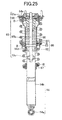
- FIGS. 24 and FIG. 25 illustrate a state in which a spring structure 60 according to a fifth embodiment of the present invention is mounted to the damper D.
- a clockwise spring 61 arranged on the upper side of the spring structure 60 has a diameter larger than a diameter of a counterclockwise spring 62 arranged on the lower side thereof.
- the counterclockwise spring 62 has substantially the same diameter and length as those of the above-mentioned counterclockwise spring 22 or the like
- the clockwise spring 61 employs a compression coil spring having a diameter larger than that of the above-mentioned counterclockwise spring.
- the damper D to which the spring structure 60 is mounted includes an upper spring seat portion 66 formed on a fixed portion 65a of an inner shaft portion 65 and having a diameter corresponding to the diameter of the clockwise spring 61.
- a piston rod 65b is covered with a bellows-like cover member 68.
- a lower spring seat portion 67 has a configuration similar to the configuration of the above-mentioned spring seat 53, and the lower end portion of the counterclockwise spring 62 is located at a position defined by a recess 67a formed in the upper surface of the lower spring seat portion 67.
- the both upper and lower end portions of the clockwise spring 61 and the upper end portion of the counterclockwise spring 62 are formed into flat surfaces orthogonal to the axial direction of the spring structure 60.
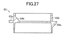
- the lower end portion of the counterclockwise spring 62 has a shape made just by cutting and are not provided with an end turn portion. As illustrated in FIGS. 26 and FIG.
- a spring seat 63 includes an abutting plate portion 63a, a tubular portion 63b, and a plurality of ribs 64a, 64b provided on both upper and lower surfaces of the abutting plate portion 63a, respectively.
- the tubular portion 63b is formed into a cylindrical shape with a short length in the axial direction.
- the abutting plate portion 63a is formed into an annular plate portion protruding both radially outwardly and radially inwardly from a center portion in the axial direction of the tubular portion 53b.
- the six ribs 64a are formed at equal intervals in the circumferential direction and each of the ribs 64a bridges between the upper surface of the inner circumference of the abutting plate portion 63a and the inner circumferential surface of the tubular portion 63b.
- the six ribs 64b are formed at equal intervals in the circumferential direction and each of the six ribs 64b bridges between the lower surface of the outer peripheral part of the abutting plate portion 63a and the outer peripheral surface of the tubular portion 63b.
- the ribs 64a and the ribs 64b are arranged in a staggered manner along the circumferential direction such that each of the ribs 64a is situated at a center between the two adjacent ribs 64b in a state illustrated in FIG. 26(a) and FIG. 26(c) .
- positions in the circumferential direction of the ribs 64a, 64b may be aligned.
- the upper and lower surfaces of the abutting plate portion 63a are formed into flat surfaces.
- the lower end portion of the clockwise spring 61 abuts on the upper surface of the outer peripheral part of the abutting plate portion 63a.
- the upper end portion of the counterclockwise spring 62 abuts on the lower surface of the inner circumferential part of the abutting plate portion 63a.
- the lower end portion of the clockwise spring 61 is engaged with the outer peripheral surface of the tubular portion 63b
- the upper end portion of the counterclockwise spring 62 is engaged with the inner circumferential surface of the tubular portion 63b.
- Other configurations of the spring structure 60 are the same as those of the above-mentioned spring structure 20. Therefore, the same components are denoted by the same reference symbols, and description thereof is omitted.
- the spring structure 60 can be arranged while not inviting interference with the front wheel FL/FR even when the counterclockwise spring 62 is positioned in the vicinity of the front wheel FL/FR to consequently have a narrow space for the arrangement, for example, the spring structure 60 is arranged in proximity to the front wheel FL/FR.
- the counterclockwise spring 62 can be arranged in the narrow space by employing a small spring as the counterclockwise spring 62.
- Other functions and effects of the spring structure 60 are the same as those of the above-mentioned spring structure 20.
- each of the springs 61, 62, on which the spring seat 63 abuts may be polished to increase a flat surface portion, and both of the springs 61, 62 may be bonded to the spring seat 63.
- FIG. 28 illustrates a state in which a spring structure 70 according to a sixth embodiment of the present invention is mounted to the damper D.
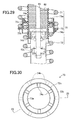
- a spring seat 73 includes, as illustrated in FIG. 29 and FIG. 30 (FIG. 29 is a sectional view of the spring seat 73 taken along the line 29-29 of FIG. 30 ), an upper abutting plate portion 73a, a lower abutting plate portion 73b, a tubular portion 73c, a plurality of ribs 74a provided on the upper surface of the upper abutting plate portion 73a, and a plurality of ribs 74b provided on the lower surface of the lower abutting plate portion 73b.
- the tubular portion 73c is formed into a cylindrical shape with a short length in the axial direction.
- the upper abutting plate portion 73a forms an annular plate portion protruding radially inwardly from a higher position than a center portion in the axial direction of the inner circumferential surface of the tubular portion 73c.
- the lower abutting plate portion 73b forms an annular plate portion protruding radially outwardly from a lower position than a center portion in the axial direction of the outer peripheral surface of the tubular portion 73c.
- the six ribs 74a are formed at equal intervals in the circumferential direction and each of the six ribs 74a bridges between the upper surface of the upper abutting plate portion 73a and the inner circumferential surface of the tubular portion 73c.
- the six ribs 74b are formed at equal intervals in the circumferential direction and each of the six ribs 74b bridges between the lower surface of the lower abutting plate portion 73b and the outer peripheral surface of the tubular portion 73c.
- the ribs 74a and the ribs 74b are arranged in a staggered manner along the circumferential direction, and each of the ribs 74a is situated at a center portion between the two adjacent ribs 74b in a state illustrated in FIG. 30 .
- the upper and lower surfaces of the upper abutting plate portion 73a and the upper and lower surfaces of the lower abutting plate portion 73b are shaped into flat surfaces.
- An upper end portion of a counterclockwise spring 72 abuts on the lower surface of the upper abutting plate portion 73a.
- a lower end portion of a clockwise spring 71 abuts on the upper surface of the lower abutting plate portion 73b.
- the lower end portion of the clockwise spring 71 is engaged with the outer peripheral surface of the tubular portion 73c
- the upper end portion of the counterclockwise spring 72 is engaged with the inner circumferential surface of the tubular portion 73c.
- the clockwise spring 71 and the counterclockwise spring 72 partially overlap each other in the up-and-down direction.
- Other configurations of the spring structure 70 are the same as those of the above-mentioned spring structure 60. Therefore, the same components are denoted by the same reference symbols, and description thereof is omitted. According to the spring structure 70, it is possible to reduce the length in the axial direction. Other functions and effects of the spring structure 70 are the same as those of the above-mentioned spring structure 60. Also in this structure, a portion of each of the springs 71, 72, on which the spring seat 73 abuts, may be polished to increase a flat surface portion, and both of the springs 71, 72 may be bonded to the spring seat 63.
- the above-mentioned spring structures 20 to 70 according to the first to sixth embodiments and Modified Examples 1 to 3 may be assembled to the rear part of the suspension of the automobile illustrated in FIG. 2 .
- the spring structure 20a arranged toward the rear wheel RL/RR illustrated in FIG. 2 is mounted separately from the damper D, and is arranged at a position between a shaft S (moving section) for connecting the rear wheel RL/RR and the body 11 (base) while being spaced from the damper D.
- the spring structure 20a may employ any one of the above-mentioned spring structures 20, 30, 30a, 30b, 40, 50, 55a, 60, 70.
- any one of the spring structures 20 to 70 for example, the spring structure 20, where the clockwise spring 21 is arranged in the upper portion of the spring structure and the counterclockwise spring 22 is arranged in the lower portion thereof, is assembled to one of the dampers D.
- a spring structure 75 is assembled to the other of the dampers D and has the same configuration as that of the spring structure 20, except that a counterclockwise spring 76 is arranged in the upper portion of the spring structure and a clockwise spring 77 is arranged in the lower portion thereof.
- FIG. 31 illustrates a front view of the vehicle body 11 in which the spring structure 20 is arranged toward the front wheel FR and the spring structure 75 is arranged toward the front wheel FL.
- FIG. 32 illustrates a front view of the vehicle body 11 in which the spring structure 75 is arranged toward the front wheel FR and the spring structure 20 is arranged toward the front wheel FL.
- the spring seat 23 rotates in the clockwise direction when the spring structure 75 is viewed from above, the spring seat 23 rotates in the counterclockwise direction when the spring structure 20 is viewed from above.
- the front portion of the vehicle body 11 is supported by the front wheels FR, FL through the spring structures 20, 75 with good balance.
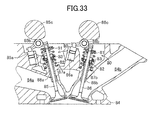
- FIG. 33 illustrates a spring structure 80 according to a seventh embodiment of the present invention. Except for being inverted in up-and-down direction, the spring structure 80 has the same configuration as that of the above-mentioned spring structure 30, and includes a counterclockwise spring 81, a clockwise spring 82, and a spring seat 83. Further, as illustrated in FIG. 33 , the spring structure 80 is assembled to a valve drive device for each of an exhaust valve 85 and an intake valve 86 of a cylinder head 84 of an engine.
- the exhaust valve 85 is arranged to be able to advance to/retreat from an exhaust port 84a through a valve guide 88a.
- the intake valve 86 is arranged to be able to advance to/retreat from an intake port 84b through a valve guide 88b.
- the spring structure 80 is arranged on each of the outer peripheral side of the exhaust valve 85 and the outer peripheral side of the intake valve 86.
- the lower end portion of the spring structure 80 is supported by a spring seat portion 87a/87b formed on a main body side of the cylinder head 84.
- the upper end portions of the spring structure 80 is fixed to each of the upper end portion of the exhaust valve 85 and the upper end portion of the intake valve 86.
- the spring structure 80 is mounted such that the counterclockwise spring 81 is situated on the upper side of the spring structure and the clockwise spring 82 is situated on the lower side thereof.
- the upper end portion of the exhaust valve 85 and the upper end portion of the intake valve 86 respectively receive, through a rocker arm 85b, 86b moving around a hydraulic lash adjuster 85a, 86a as a fulcrum, drive forces from an exhaust cam shaft 85c and an intake cam shaft 86c rotated by driving of a crank shaft (not shown).
- the drive forces drive the exhaust valve 85 and the intake valve 86.
- the intake valve 86 is opened during an intake process to send the air, which is supplied from an intake system (not shown) through the intake port 84b, into the cylinder head 84 of the engine, and is closed during an exhaust process.
- the exhaust valve 85 is opened during the exhaust process to send out an exhaust gas, which is emitted out of the cylinder, into an exhaust passage through the exhaust port 84a, and is closed during the intake stroke.
- the spring structures 80 urge the exhaust valve 85 and the intake valve 86 upward, and cause upward and downward movements of the exhaust valve 85 and the intake valve 86 to follow rotations of the exhaust cam shaft 85c and the intake cam shaft 86c.
- the cylinder head 84 serves the base, and the exhaust valve 85 or the intake valve 86 serve the moving section.
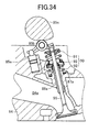
- FIG. 34 illustrates a spring structure 90 according to an eighth embodiment of the present invention.
- the spring structure 90 has substantially the same configuration as that of the above-mentioned spring structure 40, and includes a counterclockwise spring 91, a clockwise spring 92, and a spring seat 93. Further, as illustrated in FIG. 34 , the spring structure 90 is assembled to each of an exhaust valve 95 and an intake valve (not shown) of a cylinder head 94 of the engine. Also in this embodiment, similarly to the seventh embodiment, the counterclockwise spring 91 is situated in the upper part of the spring structure, and the clockwise spring 92 is situated in the lower part thereof. Other configurations of the spring structure 90 are the same as those of the above-mentioned spring structure 80.
- a spring structure having the same configuration as that of the above-mentioned spring structure 20, 30a, 30b, 50, 50a, 60, or 70 may be assembled to the exhaust valve 95 or the intake valve of the engine 94.
- FIG. 35 and FIG. 36 illustrate a state inwhich a spring structure 100 according to a ninth embodiment of the present invention is assembled to the damper D for the suspension of the automobile.
- a clockwise spring 101 and a counterclockwise spring 102 are respectively reduced in length relative to the clockwise spring 21 and the counterclockwise spring 22 of the spring structure 20.
- a well-known auxiliary spring (helper spring) 106 is arranged above the clockwise spring 101 through an intermediate seat 105.
- the auxiliary spring 106 is provided to prevent clearance from causing between the clockwise spring 101 and the counterclockwise spring 102 at the time of maximum expansion, and to ensure rebump stroke.
- the auxiliary spring 106 is constituted by a spring having a spring constant lower than that of the clockwise spring 101 and the counterclockwise spring 102. Further, the auxiliary spring 106 is formed into a spiral shape obtained by coiling a plate with a small width. When the automobile is stopped, the auxiliary spring 106 shrinks to have a cylindrical shape with no clearance as illustrated in FIG. 36 .
- a spring seat 103 arranged between the clockwise spring 101 and the counterclockwise spring 102 is configured substantially in the same manner as the above-mentioned spring seat 23.
- the intermediate seat 105 has substantially the same configuration as that of the spring seat 103, and is formed into such a shape that a cylindrical tubular portion 105b is coupled onto an outer periphery of an annular abutting plate portion 105a.
- a length in the up-and-down direction of the tubular portion 105b is slightly smaller than a length in the up-and-down direction of a tubular portion 103b of the spring seat 103.
- Other configurations of the spring structure 100 are the same as those of the above-mentioned spring structure 20. Therefore, the same components are denoted by the same reference symbols, and description thereof is omitted.
- the auxiliary spring 106 when a force for shrinking the spring structure 100 is applied to the spring structure 100, the auxiliary spring 106 first shrinks to become a cylindrical shape with no clearance between its portions, and then the clockwise spring 101 and the counterclockwise spring 102 shrink. Further, when the force for shrinking the spring structure 100 is removed, the clockwise spring 101 and the counterclockwise spring 102 first expand to return to original states, and then the auxiliary spring 106 expands to return to an original state. In this embodiment, in the state illustrated in FIG. 35 , the auxiliary spring 106 prevents clearance from causing between the clockwise spring 101 and the counterclockwise spring 102.
- each of the springs 101, 102, on which the spring seat 103 abuts may be polished to increase a flat surface portion, and both of the springs 101, 102 may be bonded to the spring seat 103.
- FIG. 37 and FIG. 38 illustrate a spring structure 110 according to a tenth embodiment of the present invention.
- the spring structure 110 is used for the suspension of the automobile.
- a clockwise spring 111 employs a variable rate spring including a low spring constant portion 111a in its upper part and a high spring constant portion 111b in its lower part.
- an axial length of the clockwise spring 111 is larger than an axial length of a counterclockwise spring 112.
- a spring constant of the counterclockwise spring 112 is equal to a spring constant of the high spring constant portion 111b of the clockwise spring 111.
- the low spring constant portion 111a of the clockwise spring 111 is provided to achieve an object similar to the object for the above-mentioned auxiliary spring 106.
- Other configurations of the spring structure 110 are the same as those of the above-mentioned spring structure 20. Therefore, the same components are denoted by the same reference symbols, and description thereof is omitted.
- the low spring constant portion 111a of the clockwise spring 111 first shrinks to become a cylindrical shape with no clearance between its portions, and then the high spring constant portion 111b of the clockwise spring 111 and the counterclockwise spring 112 shrink. Also in this embodiment, when the spring structure 110 is mounted to the vehicle body 11 of the automobile, the low spring constant portion 111a of the clockwise spring 111 shrinks to become a cylindrical shape with no clearance when the automobile is stopped.
- the high spring constant portion 111b of the clockwise spring 111 and the counterclockwise spring 112 first expand to return to original states, and then the low spring constant portion 111a of the clockwise spring 111 expands to return to an original state. Also in this embodiment, in the state illustrated in FIG. 37 , the low spring constant portion 111a of the clockwise spring 111 prevents clearance from causing between the high spring constant portion 111b of the clockwise spring 111 and the counterclockwise spring 112.
- the low spring constant portion 111a of the clockwise spring 111 ensures the stroke required when the high spring constant portion 111b of the clockwise spring 111 and the counterclockwise spring 112 expand to return to the original states.
- Other functions and effects of the spring structure 110 are the same as those of the above-mentioned spring structure 20.
- a portion of each of the springs 111, 112, on which the spring seat 23 abuts, may be polished to increase a flat surface portion, and both of the springs 111, 112 may be bonded to the spring seat 23.
- the spring structure according to the present invention is not limited to the above-mentioned embodiments, and can be modified as needed for implementation.
- the coaxially holding portion of the spring seat 23 or the like is constituted by the cylindrical tubular portion 23b or the like.
- the coaxially holding portion may be constituted by a plurality of projections, etc.
- the abutting plate portion of the spring seat 23 or the like may be constituted by a circular plate portion or the like instead of the annular plate portion.
- the spring structure according to the present invention is not limited to use for a vehicle such as an automobile or an engine, and may be used for a product provided with such a mechanism that a moving section advances to/retreats from a base.
- the clockwise spring 21 or the like and the counterclockwise spring 22 or the like are arranged such that the start points of the effective winding, which corresponds to each other, of the clockwise spring 21 or the like and the counterclockwise spring 22 or the like are shifted by 180 degrees in the circumferential direction around the axis of the spring.
- the shift degrees is not limited to 180 degrees, and it is only necessary to prevent the boundary portion between the clockwise spring 21 or the like and the counterclockwise spring 22 or the like from being displaced together with the spring seat 23 or the like in the direction orthogonal to the axial direction, and to maintain the clockwise spring 21 or the like and the counterclockwise spring 22 or the like in a substantially straight state as a whole.
- the shift degrees be set within a range of 180 ⁇ 45 degrees.
- a spring structure 120 illustrated in FIG. 39 as Reference Example may be used.
- the spring structure 120 includes only a counterclockwise spring 121 and a clockwise spring 122, and does not include a spring seat.
- the counterclockwise spring 121 has bonding surfaces 121a, 121b formed on the lower end surface thereof polished into a flat surface
- the clockwise spring 122 has bonding surfaces 122a, 122b formed on the upper end surface thereof polished into a flat surface.
- the counterclockwise spring 121 and the clockwise spring 122 are bonded to each other with an adhesive such that the bonding surface 121a and the bonding surface 122b overlap each other, and the bonding surface 121b and the bonding surface 122a overlap each other.
- the line 1 of FIG. 39 indicates a position of a joint surface between the counterclockwise spring 121 and the clockwise spring 122.
- a part indicated by solid lines constitutes the lower end surface of the counterclockwise spring 121
- a part indicated by broken lines constitutes the upper end surface of the clockwise spring 122.
Landscapes
- Engineering & Computer Science (AREA)
- General Engineering & Computer Science (AREA)
- Mechanical Engineering (AREA)
- Springs (AREA)
- Vehicle Body Suspensions (AREA)
- Fluid-Damping Devices (AREA)
Abstract
Description
- The present invention relates to a spring structure for various use, such as a suspension spring of an automobile, and a spring to be assembled to an intake valve or an exhaust valve of an engine.
- Conventionally, for example, an automobile, a motorcycle, etc. includes a suspension for rockably coupling a wheel and a vehicle body together through an arm, a link, a rod, or the like. The suspension prevents impact and vibration of the wheel from being transmitted to the vehicle body by a damper provided with a spring structure. For example, in a suspension spring (spring structure) disclosed in
JP 10-26166 A - As a result of experiments, the inventors of the present invention found that the above-mentioned conventional suspension spring has the following problems. Specifically, along with expansion and shrinkage of the suspension spring, both ends of the suspension spring are displaced in a twisting direction and receive a torsional force. Consequently, an excess frictional force may be generated at a contacting portion between the one end of the suspension spring and the vehicle body or a contacting portion between the other end of the suspension spring and the wheel side, or the torsional force may act on the suspension, which may have an influence on performance of the damper and the suspension. This similarly applies to a structure where the suspension spring includes a single compression coil spring. Further, springs for various use other than for the suspension spring have similar problems.
- The present invention has been made to solve the above-mentioned problems, and has an object to provide a spring structure, which prevents the discrepancy in the twisting direction and the torsional force from occurring at the ends of the compression coil spring along with expansion and shrinkage, and solves a new problem involved with the countermeasures therefor, to thereby improve performance.
- In order to achieve the above-mentioned object, a spring structure according to the present invention has the following structural characteristic. Specifically, the spring structure, which is mounted between a base and a moving section which advances to/retreats from the base, includes two compression coil springs different in winding directions, in which one end portions of the two compression coil springs are respectively supported on the base and the moving section directly or through a predetermined member, the other end portions of the two compression coil springs are respectively abutted on front and back surfaces of a spring seat interposed between the other end portions in a state where the other end portions are shifted, with reference to start points of effective windings of the two compression coil springs or end portions of element wires of the two compression coil springs, from each other in position in a circumferential direction around an axis of the two compression coil springs, the two compression coil springs are coaxially arranged through the spring seat, and the spring seat is movable in an axial direction of the two compression coil springs and in the circumferential direction around the axis of the two compression coil springs.
- According to the spring structure of the present invention, the two compression coil springs different in the winding directions are arranged in series through the spring seat so as to be coaxially positioned. Further, the spring seat is movable in the axial direction and in the circumferential direction around the axis of the two compression coil springs, and hence the spring seat freely moves on reception of a force from the two compression coil springs. Further, the two compression coil springs have the different winding directions, and hence, at the time of expansion and shrinkage, the end portions toward the spring seat of the two compression coil springs are turned (rotated) in the same direction, to thereby turn the spring seat in the circumferential direction around the axis of the compression coil springs. Thus, a torsional force generated in the two compression coil springs is released through rotation of the spring seat, and discrepancy in the twisting direction and the torsional force do not occur at both ends of the compression coil springs. In this way, it is possible to obtain the spring structure capable of exerting preferable performance.
- Further, according to the spring structure of the present invention, the other end portions of the two compression coil springs, which face to each other through the spring seat, are shifted from each other in position in the circumferential direction around the axis of the two compression coil springs with reference to the start points of the effective windings of the two compression coil springs or the end portions of the element wires of the two compression coil springs. Thus, when a large force is applied to the two compression coil springs to shrink the spring structure, the force is equally applied to both sides of an axis of the spring structure, and thus the two compression coil springs are maintained in a straight state as a whole. In this regard, for example, an auxiliary spring, a seat member or the like is provided as the predetermined member between the one end portion of each of the two compression coil springs and the base or the moving section.
- Further, the spring structure according to the present invention has another following structural characteristic. Specifically, the shift, provided in the circumferential direction around the axis of the two compression coil springs, between the other end portions of the two compression coil springs abutting on the spring seat is set within a range of 180±45 degrees with reference to the start points of the effective windings or the end portions of the element wires by a degree.
- The start point of the effective winding defined in the above structure corresponds to a point at which an end-side portion of each compression coil spring is separated from a member abutted on the end-side portion, or a point at which the effective winding of the compression coil spring starts from the end turn portion of the compression coil spring, that is, a boundary between a contact portion and a non-contact portion each of which is defined between the end-side portion of the compression coil spring and the abutted member, or a boundary between the effective winding and the end turnportionof the compression coil spring. Further, the end portion of the element wire corresponds to a distal end surface or a distal end of the compression coil spring. As described above, the shift, provided in the circumferential direction around the axis of the two compression coil springs, between the other end portions of the two compression coil springs abutting on the spring seat is set with reference to the start points of the effective windings or the end portions of the element wires by a degree, and thus it is possible to precisely set the shift amount of the other end portions. Consequently, the more preferred spring structure can be obtained. The most preferred shift amount in this structure is 180 degrees of the shift between the end portions of the element wires or between the start points of the effective windings in the other end portions of the two compression coil springs, the shift being provided in the circumferential direction around the axis of the compression coil springs.
- Further, the spring structure according to the present invention has still another following structural characteristic. Specifically, the both front and back surfaces of the spring seat, on which the other end portions of the two compression coil springs abut, are formed into flat surfaces, and the other end portions of the two compression coil springs which abut on the spring seat are formed into flat surfaces orthogonal to the axis of the two compression coil springs. With this, the two compression coil springs can be arranged in right coaxial manner through the spring seat, and hence performance of the spring structure can be further improved. Further, in this structure, engagement sections, positioning sections, and the like, which are engaged together, can be provided between the end portions of the two compression coil springs and the both front and back surfaces of the spring seat. Thus, the end portions of the compression coil springs can be positioned at appropriate positions of the spring seat.
- Further, the spring structure according to the present invention has still another following structural characteristic. Specifically, the spring seat includes: an abutting plate portion on which the other end portions of the two compression coil springs abut; and a coaxially holding portion, which coaxially holds the two compression coil springs, provided to both front and back surfaces of the abutting plate portion.
- As the spring seat in this structure, spring seats with various shapes can be used. For example, the spring seat may include an abutting plate portion constituted by an annular or circular plate portion, and a coaxially holding portion constituted by a tubular portion provided at an outer periphery of the abutting plate portion. Alternately, the spring seat may include an abutting plate portion constituted by an annular plate portion, and a coaxially holding portion constituted by a tubular portion provided at an inner circumference of the annular abutting plate portion. In a case where the coaxially holding portion constituted by the tubular portion is provided at the outer periphery of the annular or circular abutting plate portion, the end portions of the two compression coil springs can be inserted into the tubular portion respectively from above and below the tubular portion, and thus the two compression coil springs can be coaxially holed. Further, the tubular portion can protect the end portions toward the spring seat of the two compression coil springs.
- Further, in a case where the coaxially holding portion constituted by the tubular portion is provided at the inner circumference of the annular abutting plate portion, the end portions of the two compression coil springs are positioned at the outer periphery of the tubular portion respectively from above and below the tubular portion, and thus the two compression coil springs can be coaxially held. Further, according to this way, it is possible to prevent extraneous material from being accumulated inside the tubularportion. Because, as described above, the other end portions of the two compression coil springs are shifted in position in the circumferential direction around the axis of the two compression coil springs and the coaxially holding portion is provided to the spring seat, the two compression coil springs can be more reliably held coaxially.
- In addition, the spring seat may include the abutting plate portion constituted by an annular plate portion, a tubular portion protruding from an inner circumferential portion of the annular abutting plate portion in one direction, and a tubular portion protruding from an outer peripheral portion of the annular abutting plate portion in the other direction. In this structure, when one end portion of one of the compression coil springs is positioned at an outer periphery of the tubular portion protruding in the one direction, and one end portion of the other one of the compression coil springs is positioned inside the tubular portion protruding in the other direction, it is possible to reliably prevent the end portions toward the spring seat of the two compression coil springs from being displaced from the axial with respect to the abutting plate portion. Note that, the coaxially holding portion provided to the both front and back surfaces of the abutting plate portion according to the present invention may include a coaxially holding portion protruding from an outer peripheral edge portion and an inner circumferential edge portion of the abutting plate portion toward the both front side and back side of the abutting plate portion. Further, the coaxially holding portion may not be tubular. The coaxially holding portion only needs to hold the two compression coil springs coaxially.
- Further, the spring structure according to the present invention has still another following structural characteristic. Specifically, the both front and back surfaces of the spring seat, on which the other end portions of the two compression coil springs are disposed, have engaging protrusions formed thereon which allow the end portions of the element wires of the two compression coil springs to abut to the engaging protrusions.
- With this, the end portions of the element wires of the compression coil springs abut on the engaging protrusions, and thus the positions of the compression coil springs can be precisely defined with respect to the spring seat.
- Further, the spring structure according to the present invention has still another following structural characteristic. Specifically, the other end portions of the two compression coil springs abutting on the spring seat are provided with engaged recesses, and the both front and back surfaces of the spring seat, on which the other end portions of the two compression coil springs abut, have engaging protrusions formed thereon which allow the engaged recesses of the two compression coil springs to be engaged to engaging protrusions.
- With this, the engaged recesses of the compression coil springs are engaged on the engaging protrusions, and thus the positions of the compression coil springs can be precisely defined with respect to the spring seat. The end portions in this structure is defined as distal end portions of the compression coil springs and vicinities of the distal end portions, and thus the scope of the end portions include end surfaces of the compression coil springs.
- Further, the spring structure according to the present invention has still another following structural characteristic. Specifically, the other end portions of the two compression coil springs abutting on the spring seat have shapes made just by cutting, and the both front and back surfaces of the spring seat, on which the end portions of the two compression coil springs abut, have engagement recesses formed thereon which allow the end portions of the element wires of the two compression coil springs to be engaged to the engagement recesses.
- With this, the compression coil springs assembled to the spring structure have the end portions formed into end surfaces having shapes made just by cutting and not provided with processing for forming the end portions into flat surfaces orthogonal to the axial direction. And hence, it is possible to reduce manufacturing cost. Further, the engagement recess in this structure preferably includes a recess having a surface capable of supporting at least part in the end surface of the compression coil spring and the peripheral surface of a vicinity of the end portion of the compression coil spring, to thereby prevent the end portion of the compression coil spring from being misaligned with respect to the spring seat.
- In addition, according to the spring structure of the present invention, it is preferred that, portions of the spring seat on which the other end portions of the two compression coil springs abut are respectively provided with recesses shifted in position in the circumferential direction, and the other end portions of the two compression coil springs abutting on the spring seat are positioned in the recesses, respectively. The end portions in this structure are also defined as the distal end portions of the compression coil springs and vicinities of the distal end portions. With this, it is possible to reduce a length of the spring structure in the axial direction.
- Further, the spring structure according to the present invention has still another following structural characteristic. Specifically, the two compression coil springs different in the winding directions includes compression coil springs having different diameters. With this, in a case where a space for placing the spring structure is narrow, the compression coil spring with a smaller diameter can be arranged in the narrow space, and thus the spring structure can be mounted.
- Further, the spring structure according to the present invention has still another following structural characteristic. Specifically, the two compression coil springs different in the winding directions include compression coil springs having different diameters, and the portions of the spring seat on which the other end portions of the two compression coil springs abut are formed into such shape that the portions of the spring seat are positioned on different levels in the axial direction so that the two compression coil springs partially overlap each other in the axial direction. With this, in a case where a space for placing the spring structure is narrow, a compression coil spring with a smaller diameter can be arranged in the narrow space, and thus the spring structure can be mounted. Further, the length of the spring structure in the axial direction can be reduced, and hence the spring structure can be arranged on a place narrowed in the up-and-down direction.
- Further, the spring structure according to the present invention has still another following structural characteristic. Specifically, the two compression coil springs different in the winding directions are substantially same in characteristic shown when the two compression coil springs shrink and defining a torsion angle in the twisting direction with respect to a displacement amount of the spring. With this, when the two compression coil springs expand and shrink simultaneously, the torsion angles caused therein are substantially equal. As a result, the torsional force generated in the two compression coil springs is completely released by turning of the spring seat. Thus, it is possible to completely prevent discrepancy in the twisting direction and the torsional force from occurring at the both ends of the compression coil springs.
- Further, the spring structure according to the present invention has still another following structural characteristic. Specifically, a telescopic shaft includes an inner shaft portion which includes a spring seat portion on an outer peripheral portion of the inner shaft portion, and an outer shaft portion which includes a spring seat portion on an outer peripheral portion of the outer shaft portion and is assembled to the inner shaft portion to be movable in the axial direction, and one of the inner shaft portion and the outer shaft portion of the telescopic shaft serves as the base, and the other one of the inner shaft portion and the outer shaft portion serves as the moving section so that the spring structure is disposed between the spring seat portions on the outer periphery of the telescopic shaft.
- In this structure, the telescopic shaft may employ a damper for a vehicle, or a mechanism including intake and exhaust valves of an engine and valve guides for slidably supporting the intake and exhaust valves. Further, according to the present invention, an insertion hole may be formed in a center of the spring seat, and the telescopic shaft may pass through the insertion hole of the spring seat.
-
-
FIG. 1 is a front view illustrating a state in which a spring structure according to a first embodiment is arranged between a vehicle body and a front wheel of an automobile; -
FIG. 2 is a front view illustrating a state in which the spring structure is arranged between the vehicle body and a rear wheel of the automobile; -
FIG. 3 is a front view of the spring structure according to the first embodiment; -
FIG. 4 is a sectional view of the spring structure according to the first embodiment; -
FIG. 5 is a front view illustrating positions of a spring structure according to Comparative Example, at which force is applied; -
FIG. 6 is a front view illustrating a state in which the spring structure illustrated inFIG. 5 shrinks; -
FIG. 7 is a front view illustrating positions of the spring structure according to the first embodiment, at which the force is applied; -
FIG. 8 is a front view illustrating a state in which the spring structure illustrated inFIG. 7 shrinks; -
FIG. 9 is a graph showing a relation between a torsion angle and a displacement amount of a coil spring; -
FIG. 10 is a front view of a main part of a spring structure according to a second embodiment; -
FIG. 11 is a sectional view of the main part of the spring structure according to the second embodiment; -
FIG. 12 is a front view of a main part of a spring structure according to Modified Example 1; -
FIG. 13 is a sectional view taken along the line 13-13 ofFIG. 12 ; -
FIG. 14 is a front view of a main part of a spring structure according to Modified Example 2; -
FIG. 15 is a bottom view of a lower surface of a clockwise spring provided to the spring structure according to Modified Example 2; -
FIG. 16 is a front view of a main part of a spring structure according to a third embodiment; -
FIG. 17 is a sectional view of the main part of the spring structure according to the third embodiment; -
FIG. 18 is a front view of a main part of a spring structure according to a fourth embodiment; -
FIG. 19 is a sectional view of the main part of the spring structure according to the fourth embodiment; -
FIGS. 20 illustrate a spring seat included in the spring structure according to the fourth embodiment, in which a part (a) is a left-hand side view, a part (b) is a plan view, and a part (c) is a right-hand side view; -
FIG. 21 is a sectional view taken along the line 21-21 ofFIG. 20(b) ; -
FIG. 22 is a front view of a main part of a spring structure according to Modified Example 3; -
FIG. 23 is a sectional view of the main part of the spring structure according to Modified Example 3; -
FIGS. 24 illustrate a spring structure according to a fifth embodiment, in which a part (a) is a plan view and a part (b) is a front view; -
FIG. 25 is a sectional view taken along the line 25-25 ofFIG. 24(a) ; -
FIGS. 26 illustrate a spring seat included in the spring structure according to the fifth embodiment, in which a part (a) is a plan view, a part (b) is a front view, and a part (c) is a bottom view; -
FIG. 27 is a sectional view taken along the line 27-27 ofFIG. 26(c) ; -
FIG. 28 is a sectional view of a spring structure according to a sixth embodiment; -
FIG. 29 is a sectional view of amainpart of the spring structure according to the sixth embodiment; -
FIG. 30 is a plan view of a spring seat included in the spring structure according to the sixth embodiment; -
FIG. 31 is an explanatory diagram illustrating a state in which the spring structure according to the first embodiment and a spring structure different from the former spring structure in arrangement of the clockwise spring and a counterclockwise spring are mounted to the body; -
FIG. 32 is an explanatory diagram illustrating a state in which both the spring structures illustrated inFIG. 31 that are in arrangement reverse to that ofFIG. 31 are mounted to the vehicle body; -
FIG. 33 is a sectional view illustrating a state in which a spring structure according to a seventh embodiment is assembled to each of an intake valve and an exhaust valve of an engine; -
FIG. 34 is a sectional view illustrating a state in which a spring structure according to an eighth embodiment is assembled to the intake valve of the engine; -
FIG. 35 is a front view of a spring structure according to a ninth embodiment; -
FIG. 36 is a front view illustrating a state in which the spring structure ofFIG. 35 is contracted; -
FIG. 37 is a front view of a spring structure according to a tenth embodiment; -
FIG. 38 is a front view illustrating a state in which the spring structure ofFIG. 37 is contracted; -
FIG. 39 is a front view of a main part of a spring structure according to Reference Example; and -
FIG. 40 is an explanatory diagram of a joint portion between the counterclockwise spring and the clockwise spring illustrated inFIG. 39 . - In the following, a first embodiment according to the present invention is described with reference to the drawings.
FIG. 1 illustrates aspring structure 20 according to this embodiment, andFIG. 2 illustrates aspring structure 20a. Thespring structure 20 is arranged between thebody 11 of an automobile and a front wheel FL arranged on each of a left side and the right side of the front portion of thebody 11. Thespring structure 20a is arranged between thebody 11 of the automobile and a rear wheel RL arranged on each of the left side and the right side of the rear portion of thebody 11. Each of thespring structure 20 and thespring structure 20a constitutes a part of a suspension. The suspension prevents impact and vibration from being transmitted to thebody 11 from the front wheel FL, the front wheel FR, the rear wheel RL, or the rear wheel RR. - As described in claim 12, a front part of the suspension is provided with a damper D serving as a telescopic shaft of the present invention. The damper D includes an inner shaft portion 13 (see
FIG. 4 ) serving as a base coupled to thebody 11, and a tubular outer shaft portion 14 (seeFIG. 3 andFIG. 4 ) serving as a moving section coupled to each of the front wheel FL and the front wheel FR. Thespring structure 20 is placed on an outer periphery of the damper D. Alternately, the damper D may be turned upside down, theouter shaft portion 14 as the base may be arranged toward thebody 11, and theinner shaft portion 13 as the moving section may be arranged toward the front wheel FL and the front wheel FR. Theinner shaft portion 13 includes a fixedportion 13a fixed to thebody 11, apiston rod 13b extending downward from a center portion of the fixedportion 13a through arubber mount 13d, and apiston 13c attached to an outer periphery of a lower end of thepiston rod 13b. Further, an upperspring seat portion 15 having an annular shape and a flat surface is formed on a lower surface of a lower portion of the fixedportion 13a, the lower portion having a small diameter. Acylindrical portion 15a for locking protrudes downward from the inner circumferential edge portion of the upperspring seat portion 15, having a short length in the axial direction. - The
outer shaft portion 14 includes: acoupling portion 14a coupled to anarm 16 arranged toward the front wheel FL and FR; acylinder 14b which is formed into a cylindrical body with a closed bottom and has the bottom welded to thecoupling portion 14a; apiston rod guide 14d closing an upper end opening of thecylinder 14b and supporting thepiston rod 13b so as to allow thepiston rod 13b to slide; and aspring seat portion 14c positioned slightly higher than a center in an up-and-down direction on an outer peripheral surface of thecylinder 14b. Thespring seat portion 14c includes an annular lowerspring seat portion 17 having an upper surface as a flat surface, and a cylindrical portion 17a for locking which extends upward along thecylinder 14b from an inner circumferential edge portion of the lowerspring seat portion 17 and has a short length in the axial direction. An inner circumferential surface of the cylindrical portion 17a is fixed to the outer peripheral surface of thecylinder 14b through alock ring 17b. - The
piston 13c of theinner shaft portion 13 is allowed to slide in fluid-tight contact with an inner circumferential surface of thecylinder 14b of theouter shaft portion 14. Further, oil chambers, i.e., two upper and lower chambers defined by thepiston 13c are formed inside thecylinder 14b. In addition, the oil chambers are adjacent to a high-pressure gas chamber, and are always under pressure by a free piston. Further, thepiston 13c has well-known paired flow passages extending between upper and lower surfaces of thepiston 13c. Through the paired flow passages, oil moves between the oil chambers provided above and below thepiston 13c, and thus a damping force is generated in the damper D. - Further, an upper end portion of a bellows-shaped
cover member 18 formed of an elastic member is fixed to the upperspring seat portion 15 of theinner shaft portion 13, and a lower end portion thereof extends, in a free state, to the vicinity of an upper end portion at the outer periphery of thecylinder 14b. This configuration prevents mud and the like from adhering to thepiston rod 13b. In this regard, as described later, aseat 19a is molded integrally with an upper end of thecover member 18 and sandwiched between aclockwise spring 21 and the upperspring seat portion 15. - The
spring structure 20 includes theclockwise spring 21 arranged on an upper side between the upperspring seat portion 15 and the lowerspring seat portion 17, acounterclockwise spring 22 arranged on a lower side therebetween, and aspring seat 23 arranged between theclockwise spring 21 and thecounterclockwise spring 22. Springs having the same diameter, length in the axial direction, spring constant, and the like serve as theclockwise spring 21 and thecounterclockwise spring 22. That is, theclockwise spring 21 and thecounterclockwise spring 22 have the same configuration except for a difference in winding directions. Therefore, theclockwise spring 21 and thecounterclockwise spring 22 have the same characteristic defining a torsion angle in the twisting direction (the characteristic is defined as relation between the torsion angle and the displacement amount). - Further, both end portions of the
clockwise spring 21 and both end portions of thecounterclockwise spring 22 are processed to be formed into flat surfaces orthogonal to axial direction of the springs. Further, theclockwise spring 21 includes, at both ends thereof,end turn portions counterclockwise spring 22 includes, at both ends thereof,end turn portions end turn portions FIG. 4 ) of the element wire of the spring and then comes back to the end portion A of the element wire to be adjacent to a close contact portion B, and therefore each of theend turn portions end turn portions end turn portions end turn portions - Further, in this embodiment, the
clockwise spring 21 are formed such that the start points B of the effective winding on the both end sides of theclockwise spring 21 are shifted by 180 degrees in a circumferential direction around an axis of theclockwise spring 21, and thecounterclockwise spring 22 are formed such that the start points B of the effective winding on the both end sides of thecounterclockwise spring 22 are shifted by 180 degrees in a circumferential direction around an axis of thecounterclockwise spring 22. - Further, the
spring seat 23 is formed of a molded body made of a metal material such as aluminum, and is shaped such that a cylindricaltubular portion 23b serving as a coaxially holding portion in the present invention is coupled at an outer periphery of an annularabutting plate portion 23a. The abuttingplate portion 23a is formed into an annular flat plate portion which has an inner diameter slightly larger than an outer diameter of thecover member 18 and has an outer diameter equal to or slightly larger than an outer diameter of theclockwise spring 21 and an outer diameter of thecounterclockwise spring 22. A flat surface portion at a lower end of the clockwise spring 21 (part of theend turn portion 21b) abuts on an upper surface of theabutting plate portion 23a, and a flat surface portion at an upper end of the counterclockwise spring 22 (part of theend turn portion 22a) abuts on a lower surface of theabutting plate portion 23a. - The abutting
plate portion 23a has upper and lower surfaces formed into flat surfaces, and is formed to have a constant thickness. Under a state of being orthogonal to the axial direction of theclockwise spring 21 and thecounterclockwise spring 22, the abuttingplate portion 23a abuts on the flat surface at the end of theclockwise spring 21, the flat surface at the end of thecounterclockwise spring 22, and theend turn portions tubular portion 23b is arranged such that its axial direction is along the up-and-down direction. Further, thetubular portion 23b is coupled to theabutting plate portion 23a such that the center portion in the up-and-down direction of the inner circumferential surface of thetubular portion 23b surrounds the outer periphery of theabutting plate portion 23a. Further, the lower end portion of theclockwise spring 21 is inserted into an upper interior of thetubular portion 23b, and the upper end portion of thecounterclockwise spring 22 is inserted into a lower interior of thetubular portion 23b. Through thespring seat 23, theclockwise spring 21 and thecounterclockwise spring 22 are held so as to be coaxial with each other. - It is a first highly important point that the
spring seat 23 is sandwiched by theclockwise spring 21 and thecounterclockwise spring 22 and is changed in position in accordance with forces applied from theclockwise spring 21 and thecounterclockwise spring 22. When theclockwise spring 21 and thecounterclockwise spring 22 expand and shrink, therespective springs springs spring seat 23 of theclockwise spring 21 and that of thecounterclockwise spring 22 have the same rotating (twisting) direction, to thereby turn thespring seat 23 in the circumferential direction around the axis of the spring. Therefore, torsional forces generated in theclockwise spring 21 and thecounterclockwise spring 22 are released by the turning of thespring seat 23, and thespring seat 23 moves in the axial direction of theclockwise spring 21 and thecounterclockwise spring 22. In this way, it is possible to achieve a first object of preventing occurrence of discrepancy in a twisting direction and generation of the torsional forces at both ends of a compression coil spring due to expansion and shrink. - Further, as described in detail later, it is a second highly important point that the start point B of the effective winding at the lower end of the
clockwise spring 21 and the start point B of the effective winding at the upper end of thecounterclockwise spring 22 are shifted by 180 degrees in position in the circumferential direction around the axis of theclockwise spring 21 or thecounterclockwise spring 22. Note that, in this embodiment, theclockwise spring 21 and thecounterclockwise spring 22 are arranged such that the start point B of the effective winding at the upper end of theclockwise spring 21 and the start point B of the effective winding at the lower end of thecounterclockwise spring 22 are shifted by 180 degrees in the circumferential direction around the axis of theclockwise spring 21 or thecounterclockwise spring 22. However, this point is not essential to the present invention. - As described above, in the first embodiment, the start point B of effective winding at the lower end of the
clockwise spring 21 and the start point B of effective winding at the upper end of thecounterclockwise spring 22 are shifted by 180 degrees in the circumferential direction around the axis of the spring. With this configuration, when thespring structure 20 shrinks, it is possible to prevent a boundary portion between theclockwise spring 21 and thecounterclockwise spring 22 from being displaced together with thespring seat 23 in a direction orthogonal to the axial direction, and to maintain theclockwise spring 21 and thecounterclockwise spring 22 in being straight arranged as a whole. Thus, it is possible to achieve a second object that is a new object involved with the first object. - The above point will be described in detail. The following has been found through experiments. In a structure, as a spring structure 20b according to Comparative Example illustrated in
FIG. 5 , where the start point B of effective winding at the lower end of theclockwise spring 21 and the start point B of effective winding at the upper end of thecounterclockwise spring 22 are positioned at the same positions in the circumferential direction around the axis of the spring, the spring structure 20b, when shrinking, gets into a state illustrated inFIG. 6 , to thereby affect the performance thereof. Specifically, black arrows illustrated inFIG. 5 each indicate the position of the start point B of effective winding, and large forces F are applied to the positions when theclockwise spring 21 and thecounterclockwise spring 22 shrink. - Therefore, when a force is applied in a direction of a white arrow "a" illustrated in
FIG. 6 and then the spring structure 20b shrinks, the large forces F are applied to one side relative to the axis of the spring structure 20b, and thus the boundary portion between theclockwise spring 21 and thecounterclockwise spring 22 is displaced together with thespring seat 23 in a direction of a white arrow "b", i.e., the direction orthogonal to the axial direction of the spring structure 20b. However, in a structure, as thespring structure 20 illustrated inFIG. 7 , where the start point B of effective winding at the lower end of theclockwise spring 21 and the start point B of effective winding at the upper end of thecounterclockwise spring 22 are shifted by 180 degrees in the circumferential direction around the axis of the spring, it is possible to prevent occurrence of the discrepancy illustrated inFIG. 6 . - Black arrows illustrated in
FIG. 7 also indicate the position of the start point B of effective winding of theclockwise spring 21 and that of thecounterclockwise spring 22, respectively. When theclockwise spring 21 and thecounterclockwise spring 22 shrink, the large forces F are applied to the positions indicated by the black arrows. When a force is applied in the direction of the white arrow "a" illustrated inFIG. 8 and then thespring structure 20 shrinks, the large forces F are applied to both sides relative to the axis of the spring structure 20b. Consequently, as illustrated inFIG. 8 , thespring structure 20 shrinks straight in the axial direction. In this case, only thespring seat 23 is slightly inclined relative to the axial direction of theclockwise spring 21 and thecounterclockwise spring 22. - Further, as illustrated in
FIG. 4 , theannular seat 19a molded integrally with thecover member 18 is placed between the upperspring seat portion 15 and the upper end portion of theclockwise spring 21. Further, an annularelastic seat 19b is placed between the lowerspring seat portion 17 and the lower end portion of thecounterclockwise spring 22. Each of theseat 19a and theelastic seat 19b is a well-known member for preventing self-excited vibration of the spring from being transmitted to thebody 11. Alternately, the seat is not limited thereto, and may be placed between theabutting plate portion 23a and theclockwise spring 21 or between theabutting plate portion 23a and thecounterclockwise spring 22. - According to the automobile provided with the
spring structure 20 as described above, even when the front wheels FL, FR and the like vibrate or receive impact due to a reaction force from a road surface during vehicle running, the vibration and impact are prevented from being transmitted to the vehicle body owing to action of thespring structure 20. Further, the damping force is generated owing to actuation of the damper D, and thereby the running state of the vehicle can be maintained in a preferable state. Further, in thespring structure 20 according to this embodiment, theclockwise spring 21 and thecounterclockwise spring 22 different in the winding directions are coaxially arranged through thespring seat 23. Thespring seat 23 is not fixed, but supported only by being sandwiched between theclockwise spring 21 and thecounterclockwise spring 22, and hence thespring seat 23 is movable in the axial direction of thespring structure 20 and a circumferential direction around the axis of the spring structure. - Therefore, when the
clockwise spring 21 and thecounterclockwise spring 22 expand and shrink, the end portions thereof toward thespring seat 23 have the same rotating (twisting) direction, to thereby turn thespring seat 23 in the circumferential direction around the axis of the spring. In this way, thespring structure 20 can exert a preferable performance. Further, both the upper and lower surfaces of theabutting plate portion 23a of thespring seat 23 are formed as flat surfaces, and the end portions of theclockwise spring 21 and the end portions of thecounterclockwise spring 22 are formed as flat surfaces orthogonal to the axial direction of thespring structure 20. Therefore, theclockwise spring 21 and thecounterclockwise spring 22 can be arranged in a right coaxial manner through thespring seat 23, and thereby performance of thespring structure 20 can be further improved. - In addition, the start point B of the effective winding at the lower end of the
clockwise spring 21 and the start point B of the effective winding at the upper end of thecounterclockwise spring 22 are shifted by 180 degrees in the circumferential direction around the axis of the spring, and hence, when thespring structure 20 shrinks, the boundary portion between theclockwise spring 21 and thecounterclockwise spring 22 is prevented from being displaced together with thespring seat 23 in a direction orthogonal to the axial direction of the springs. In this way, theclockwise spring 21 and thecounterclockwise spring 22 can be maintained to be straight arranged. - Further, the end portion toward the
spring seat 23 of theclockwise spring 21 and that of thecounterclockwise spring 22 are inserted, from above and below, into the inside of thetubular portion 23b of thespring seat 23. With this configuration, theclockwise spring 21 and thecounterclockwise spring 22 can be coaxially held, and the end portion toward thespring seat 23 of theclockwise spring 21 and that of thecounterclockwise spring 22 can be protected. In this regard, in a structure where surfaces of thesprings spring seat 23 abuts, are polished in order to increase the flat portion, and are bonded and fixed to thespring seat 23 with an adhesive, coaxial alignment of thesprings spring seat 23 can be united with both of thesprings - In addition, the
clockwise spring 21 and thecounterclockwise spring 22 have substantially the same characteristic for the torsion angle in the rotating direction with respect to the displacement amount of each of the springs, and hence substantially equal torsion angles occur in theclockwise spring 21 and thecounterclockwise spring 22 at the time of their expansion and shrink. As a result, the torsional forces generated in theclockwise spring 21 and thecounterclockwise spring 22 completely released in the rotating direction of thespring seat 23, and hence discrepancy in the rotating direction and forces in the rotating direction can be prevented from occurring at both ends of thespring structure 20. As shown inFIG. 9 , this characteristic can be shown by a relation between a torsion angle (degree) and a displacement amount (mm) of the coil spring, andFIG. 9 shows the relation between the torsion angle and the displacement amount when using a coil spring with an axial length of 300 mm, an inner diameter of 70 mm, a element wire diameter of 11.5 mm, and the number of the effective winding of 8.0. - In this case, when no external force is applied to the coil spring, both a value of the torsion angle and a value of the displacement amount are "0", and the coil spring is not deformed. When the maximum external force within a range where the coil spring can be deformed is applied such that the value of the torsion angle and the value of the displacement amount are maximum, a gap between one part and another part of the coil spring is eliminated such that the one part and the another part become in close contact with each other. Further, when changing from a state of "0" to a state of "close contact", an increment of the torsion angle is slightly larger than the increment of the displacement amount in a range where the value of the torsion angle and the value of the displacement amount are small. In a range where the value of the torsion angle and the value of the displacement amount are large, an increment of the torsion angle is slightly smaller than the increment of the displacement amount. However, overall, the torsion angle and the displacement amount are increased in substantial proportion.
-
FIG. 10 and FIG. 11 illustrate a main part of aspring structure 30 according to a second embodiment of the present invention. In thespring structure 30, aspring seat 33 includes an annular abuttingplate portion 33a and a cylindricaltubular portion 33b defined as the coaxially holding port ion in the present invention, thetubular portion 33b being coupled to the inner circumferential edge portion of theabutting plate portion 33a. Thetubular portion 33b is arranged such that its axial direction is along the up-and-down direction, and is coupled to theabutting plate portion 33a under a state in which the inner circumference of theabutting plate portion 33a surrounds a center portion in the up-and-down direction of the outer peripheral surface of thetubular portion 33b. Further, a lower end portion of aclockwise spring 31 abuts on the upper surface of theabutting plate portion 33a, and an upper end portion of acounterclockwise spring 32 abuts on the lower surface of theabutting plate portion 33a. Further, the lower end portion of theclockwise spring 31 and the upper end portion of thecounterclockwise spring 32 are engaged with the outer peripheral surface of thetubular portion 33b. - Other configurations of the
spring structure 30 are the same as those of the above-mentionedspring structure 20. Therefore, the same components are denoted by the same reference symbols, and description thereof is omitted. According to thespring structure 30, the lower end portion of theclockwise spring 31 and the upper end portion of thecounterclockwise spring 32 are engaged with the outer periphery of thetubular portion 33b, and thereby theclockwise spring 31 and thecounterclockwise spring 32 can be coaxially held. Further, it is possible to prevent extraneous materials such as mud from being accumulated inside thetubular portion 33b. Other functions and effects of thespring structure 30 are the same as those of the above-mentionedspring structure 20. Alternately, also in the second embodiment, similarly to the first embodiment, both of thesprings spring seat 33. Also in that structure, the portions of thesprings spring seat 33 abuts, may be preferably polished so as to be flat surfaces. -
FIG. 12 and FIG. 13 illustrate a main part of aspring structure 30a according to Modified Example 1 for the above-mentionedspring structure 30. In thespring structure 30a, aspring seat 34 includes anabutting plate portion 34a, an engagingprotrusion 34b, and an engagingprotrusion 34c. The engagingprotrusion 34b is formed on a predetermined portion of theabutting plate portion 34a, and protrudes from the upper surface of theabutting plate portion 34a. The engagingprotrusion 34c is formed to be spaced apart by 180 degrees from the portion on which the engagingprotrusion 34b is formed in theabutting plate portion 34a, and protrudes from the lower surface of theabutting plate portion 34a. Further, an end portion of an element wire of anend turn portion 31b formed at a lower end of aclockwise spring 31a forms an engagedsurface 31c that is formed as substantially vertical plane. An end portion of an element wire of anend turn portion 32b formed at an upper end of acounterclockwise spring 32a forms an engagedsurface 32c that is formed as substantially vertical plane. - The
clockwise spring 31a is arranged on the upper side of theabutting plate portion 34a under a state in which the engagedsurface 31c is abutted on the engagingprotrusion 34b, and thecounterclockwise spring 32a is arranged on the lower side of theabutting plate portion 34a under a state in which the engagedsurface 32c is abutted on the engagingprotrusion 34c. Other configurations of thespring structure 30a are the same as those of the above-mentionedspring structure 30. Therefore, the same components are denoted by the same reference symbols, and description thereof is omitted. According to thespring structure 30a, the lower end portion of theclockwise spring 31a and the upper end portion of thecounterclockwise spring 32a can be positioned at appropriate positions on thespring seat 34 while being shifted precisely by 180 degrees. Other functions and effects of thespring structure 30a are the same as those of the above-mentionedspring structure 30. Note that, also in this embodiment, similarly to the first embodiment, the portions of thesprings spring seat 34 abuts, may be polished to form flat surfaces, and both of thesprings spring seat 34. -
FIG. 14 illustrates a main part of aspring structure 30b according to Modified Example 2 for the above-mentionedspring structure 30. In thespring structure 30b, as illustrated inFIG. 15 , an engagedrecess 35b is formed in a lower surface of a distal end of anend turn portion 35a formed at a lower end of aclockwise spring 35, and, similarly to the engagedrecess 35b illustrated inFIG. 15 , an engagedrecess 36b is formed in a upper surface of a distal end of anend turn portion 36a formed at an upper end of acounterclockwise spring 36. Other configurations of thespring structure 30b are the same as those of the above-mentionedspring structure 30a. Therefore, the same components are denoted by the same reference symbols, and description thereof is omitted. - In the
spring structure 30b, theclockwise spring 35 is placed on the upper side of theabutting plate portion 34a under a state in which the engagedrecess 35b is engaged on the engagingprotrusion 34b. Further, thecounterclockwise spring 36 is placed on the lower side of theabutting plate portion 34a under a state in which the engagedrecess 36b is engaged on the engagingprotrusion 34c. Thus, the lower end portion of theclockwise spring 35 and the upper end portion of thecounterclockwise spring 36 can be positioned at appropriate positions on thespring seat 34 while being shifted precisely by 180 degrees. Other functions and effects of thespring structure 30b are the same as those of the above-mentionedspring structure 30. Also in this embodiment, similarly to the first embodiment, the portion of thesprings spring seat 34 abuts, may be polished to form flat surfaces, and both of thesprings spring seat 34. - In this regard, the
spring structure 20 according to the first embodiment may be provided with the positioning section including the engagingprotrusions surfaces spring structure 30a according to Modified Example 1, or the engagement section including the engagingprotrusions recesses spring structure 30b according to Modified Example 2. -
FIG. 16 and FIG. 17 illustrate a main part of aspring structure 40 according to a third embodiment of the present invention. In thespring structure 40, aspring seat 43 is formed by pressing a sheet metal, and has a configuration in which a cylindricaltubular portion 43b is coupledto an inner circumference of an annularabutting plate portion 43a, and a cylindricaltubular portion 43c is coupled to an outer periphery of the annular abuttingplate portion 43a. In this structure, thetubular portion 43b and thetubular portion 43c form the coaxially holding portion according to the present invention. Thetubular portion 43b is arranged such that its axial direction is along the up-and-down direction, and is coupled to theabutting plate portion 43a under a state in which the inner circumference of theabutting plate portion 43a surrounds the lower end portion of thetubular portion 43b. Further, thetubular portion 43c is arranged such that its axial direction is along the up-and-down direction, and is coupled to theabutting plate portion 43a under a state in which the outer periphery of theabutting plate portion 43a is along the upper end portion of thetubular portion 43c. - The lower end portion of a
clockwise spring 41 abuts on the upper surface of theabutting plate portion 43a, and the upper end portion of acounterclockwise spring 42 abuts on the lower surface of theabutting plate portion 43a. Further, the lower end portion of theclockwise spring 41 is engaged with the outer peripheral surface of thetubular portion 43b, and the upper end portion of thecounterclockwise spring 42 is engaged with the inner circumferential surface of thetubular portion 43c. Other configurations of thespring structure 40 are the same as those of the above-mentionedspring structure 20. Therefore, the same components are denoted by the same reference symbols, and description thereof is omitted. According to thespring structure 40, the lower end portion of theclockwise spring 41 is engaged with the outer peripheral surface of thetubular portion 43b, and the upper end portion of thecounterclockwise spring 42 is engaged with the inner circumferential surface of thetubular portion 43c. Consequently, theclockwise spring 41 and thecounterclockwise spring 42 can be coaxially held. Other functions and effects of thespring structure 40 are the same as those of the above-mentionedspring structure 20. Also in this embodiment, portions of thesprings spring seat 43 abuts, may be polished to form flat surfaces, and both of thesprings spring seat 43. -
FIG. 18 and FIG. 19 illustrate a main part of aspring structure 50 according to a fourth embodiment of the present invention. In thespring structure 50, a lower end portion of aclockwise spring 51 and an upper end portion of acounterclockwise spring 52 are not provided with the processing and thus have a shape made just by cutting. Aspring seat 53 includes an annular abuttingplate portion 53a and a cylindricaltubular portion 53b illustrated inFIGS. 20 andFIG. 21 .FIG. 20 (b) is a plan view of thespring seat 53,FIG. 20(a) is a left-hand side view ofFIG. 20(b), and FIG. 20(c) is a right-hand side view ofFIG. 20(b) . The right side and the left side ofFIG. 20(a) correspond to the upper side and the lower side of thespring seat 53, respectively, and the right side and the left side ofFIG. 20(c) correspond to the lower side and the upper side of thespring seat 53, respectively. Thespring seat 53 is integrally molded of aluminum alloy or a resin. - The
tubular portion 53b is formed into a cylindrical shape with a short axial length. The abuttingplate portion 53a is coupled onto the outer peripheral surface of thetubular portion 53b, and is formed into a plate portion which has a plurality of inclined surfaces formed on each of upper and lower surfaces of the plate portion and changing in the up-and-down direction. Specifically, a left half ofFIG. 20 (b) of the upper surface of theabutting plate portion 53a forms aninclined surface 54 that is inclined at a constant inclination from the upper part ofFIG. 20(b) to the lower part thereof. A right half ofFIG. 20(b) of the upper surface of theabutting plate portion 53a forms a curved surface that has three aligned inclined surfaces such that a center portion (right end ofFIG. 20(b) ) of the curved surface is recessed downward. - The right half of
FIG. 20 (b) of the upper surface of theabutting plate portion 53a has a part from the upper part ofFIG. 20(b) to the right end of the same figure, the part forming aninclined surface 55 that is continuous with theinclined surface 54 and is gradually inclined at the same constant inclination as that of theinclined surface 54. Further, the right half ofFIG. 20 (b) of the upper surface of theabutting plate portion 53a has a part from the right end ofFIG. 20(b) to halfway down the bottom of the same figure, the part forming aninclined surface 56 which has a short circumferential length and is gradually inclined at an inclination larger than that of theinclined surface 55. Further, a part ofFIG. 20 (b) from the lower end of theinclined surface 56 to the lower end of theinclined surface 54 forms aninclined surface 57 that is gradually inclined at an inclination smaller than that of theinclined surface 56. Thus, arecess 58 recessed downward is formed between theinclined surface 55 and theinclined surface 56. - A lower surface of the
abutting plate portion 53a is symmetrical about a point with the upper surface of theabutting plate portion 53a, and thus includesinclined surfaces recess 58a that respectively correspond to theinclined surface recess 58 in the upper surface thereof. Therecess 58a is recessed upward, and is spaced apart by 180 degrees in the circumferential direction from therecess 58 in the upper surface. Therecesses FIG. 18 , the lower portion of theclockwise spring 51 abuts on thespring seat 53 while being arranged along theinclined surfaces FIG. 18 andFIG. 21 , a corner of the end portion of the element wire of theclockwise spring 51 is located at a position defined by therecess 58. - Similarly, the upper portion of the
counterclockwise spring 52 abuts on thespring seat 53 while being arranged along theinclined surfaces 54a, 55a. A corner of the end portion of the element wire of thecounterclockwise spring 52 is located at a position defined by therecess 58a as illustrated inFIG. 21 . Therecesses recesses clockwise spring 51 and the upper portion of thecounterclockwise spring 52 are not provided with the end turn portion. And thus, the lower portion of theclockwise spring 51 is formed at the same pitch as a central portion of theclockwise spring 51, and the upper portion of thecounterclockwise spring 52 is formed at the same pitch as a central portion of thecounterclockwise spring 52. However, in a structure where theclockwise spring 51 and thecounterclockwise spring 52 are abutted on thespring seat 53, substantive start points of the effective winding exist as described below. - In this structure, the start point of the effective winding at the lower end of the
clockwise spring 51 is defined as a point at which the lower portion of theclockwise spring 51 is separated from theinclined surfaces spring seat 53, that is, a portion of theclockwise spring 51 facing a boundary portion C between theinclined surface 54 andinclined surface 57. The start point of the effective winding at the upper end of thecounterclockwise spring 52 is defined as a point at which the upper portion of thecounterclockwise spring 52 is separated from theinclined surfaces 55a, 54a of thespring seat 53, that is, a portion of thecounterclockwise spring 52 facing a boundary portion between theinclined surface 54a and theinclined surface 57a. Each of theclockwise spring 51 and thecounterclockwise spring 52 is substantially provided with an end turn portion of 3/4 of a turn. Other configurations of thespring structure 50 are the same as those of the above-mentionedspring structure 20. Therefore, the same components are denoted by the same reference symbols, and description thereof is omitted. - According to the
spring structure 50, the lower end portion of theclockwise spring 51 and the upper end portion of thecounterclockwise spring 52 are not provided with the processing and thus have a shape made just by cutting. And hence, it is possible toreducemanufacturingcost. Further,an abutmentposition between the lower end portion of theclockwise spring 51 and thespring seat 53 and an abutment position between the upper end portion of thecounterclockwise spring 52 and thespring seat 53 are shifted by 180 degrees in a circumferential direction of thespring seat 53, and hence theclockwise spring 51 and thecounterclockwise spring 52 applies forces to thespring seat 53 with good balance, to thereby stabilize a posture of thespring seat 53. - Further, the end portions of the element wires, which made just by cutting, of the upper and lower springs are shifted by 180 degrees, and the
abutting plate portion 53a forms the plate portion in which the plurality of inclined surfaces changing in the up-and-down direction and theengagement recess 58/58a are formed on the upper/lower surface of the plate portion. Thus, the lower end portion of theclockwise spring 51 and the upper end portion of thecounterclockwise spring 52 can partially overlap each other in the up-and-down direction, and hence it is possible to reduce the length in axial direction of thespring structure 50. In this regard, therecesses abutting plate portion 53a, may be shifted in the circumferential direction by other than 180 degrees, for example, by within a range of 180±45 degrees. Other functions and effects of thespring structure 50 are the same as those of the above-mentionedspring structure 20. -
FIG. 22 and FIG. 23 illustrate a main part of aspring structure 50a according to Modified Example 3 defined as Modified Example of the above-mentionedspring structure 50. In thespring structure 50a, aspring seat 59 has a configuration similar to the configuration of the above-mentionedspring seat 53. Specifically, thespring seat 59 includes an annular abuttingplate portion 59a and a cylindricaltubular portion 59b, whereas a groove-like recess 59c having a semi-circular cross-sectional shape is formed in the upper surface of theabutting plate portion 59a and a groove-like recess 59d having a semi-circular cross-sectional shape is formed in the lower surface of theabutting plate portion 59a. The groove-like recess 59c substantially conforms in shape to the lower portion of the outer peripheral surface of theclockwise spring 51 in order to increase the contact area between the lower end portion of theclockwise spring 51 and therecess 59c. The groove-like recess 59d substantially conforms in shape to the lower portion of the outer peripheral surface of thecounterclockwise spring 52 in order to increase the contact area between the upper end portion of thecounterclockwise spring 52 and therecess 59d. Further, surfaces of the groove-like recesses clockwise spring 51, and the upper surface of thecounterclockwise spring 52 are polished. By applying an adhesive onto the polished surfaces, the groove-like recess 59c and the lower end portion of theclockwise spring 51 are bonded to each other, and the groove-like recess 59d and the upper end portion of thecounterclockwise spring 52 are bonded to each other. Other configurations of thespring structure 50a are the same as those of the above-mentionedspring structure 50. - Withthisconfiguration,axialalignment between the
clockwise spring 51 and thecounterclockwise spring 52 is ensured, and thespring seat 53 is integrated with both of thesprings spring structure 50a are the same as those of the above-mentionedspring structure 50. -
FIGS. 24 andFIG. 25 illustrate a state in which aspring structure 60 according to a fifth embodiment of the present invention is mounted to the damper D. In thespring structure 60, aclockwise spring 61 arranged on the upper side of thespring structure 60 has a diameter larger than a diameter of acounterclockwise spring 62 arranged on the lower side thereof. Specifically, thecounterclockwise spring 62 has substantially the same diameter and length as those of the above-mentionedcounterclockwise spring 22 or the like, whereas theclockwise spring 61 employs a compression coil spring having a diameter larger than that of the above-mentioned counterclockwise spring. Thus, the damper D to which thespring structure 60 is mounted includes an upperspring seat portion 66 formed on a fixedportion 65a of aninner shaft portion 65 and having a diameter corresponding to the diameter of theclockwise spring 61. Similarly to the above-mentioned embodiments, apiston rod 65b is covered with a bellows-like cover member 68. - Further, a lower
spring seat portion 67 has a configuration similar to the configuration of the above-mentionedspring seat 53, and the lower end portion of thecounterclockwise spring 62 is located at a position defined by arecess 67a formed in the upper surface of the lowerspring seat portion 67. In thespring structure 60, the both upper and lower end portions of theclockwise spring 61 and the upper end portion of thecounterclockwise spring 62 are formed into flat surfaces orthogonal to the axial direction of thespring structure 60. The lower end portion of thecounterclockwise spring 62 has a shape made just by cutting and are not provided with an end turn portion. As illustrated inFIGS. 26 andFIG. 27 , aspring seat 63 includes anabutting plate portion 63a, atubular portion 63b, and a plurality ofribs abutting plate portion 63a, respectively. - The
tubular portion 63b is formed into a cylindrical shape with a short length in the axial direction. The abuttingplate portion 63a is formed into an annular plate portion protruding both radially outwardly and radially inwardly from a center portion in the axial direction of thetubular portion 53b. Further, the sixribs 64a are formed at equal intervals in the circumferential direction and each of theribs 64a bridges between the upper surface of the inner circumference of theabutting plate portion 63a and the inner circumferential surface of thetubular portion 63b. The sixribs 64b are formed at equal intervals in the circumferential direction and each of the sixribs 64b bridges between the lower surface of the outer peripheral part of theabutting plate portion 63a and the outer peripheral surface of thetubular portion 63b. Theribs 64a and theribs 64b are arranged in a staggered manner along the circumferential direction such that each of theribs 64a is situated at a center between the twoadjacent ribs 64b in a state illustrated inFIG. 26(a) and FIG. 26(c) . Alternately, positions in the circumferential direction of theribs - The upper and lower surfaces of the
abutting plate portion 63a are formed into flat surfaces. The lower end portion of theclockwise spring 61 abuts on the upper surface of the outer peripheral part of theabutting plate portion 63a. The upper end portion of thecounterclockwise spring 62 abuts on the lower surface of the inner circumferential part of theabutting plate portion 63a. Further, the lower end portion of theclockwise spring 61 is engaged with the outer peripheral surface of thetubular portion 63b, and the upper end portion of thecounterclockwise spring 62 is engaged with the inner circumferential surface of thetubular portion 63b. Other configurations of thespring structure 60 are the same as those of the above-mentionedspring structure 20. Therefore, the same components are denoted by the same reference symbols, and description thereof is omitted. - According to the
spring structure 60, thespring structure 60 can be arranged while not inviting interference with the front wheel FL/FR even when thecounterclockwise spring 62 is positioned in the vicinity of the front wheel FL/FR to consequently have a narrow space for the arrangement, for example, thespring structure 60 is arranged in proximity to the front wheel FL/FR. Specifically, while increasing strength of thespring structure 60 by employing a large spring as theclockwise spring 61, thecounterclockwise spring 62 can be arranged in the narrow space by employing a small spring as thecounterclockwise spring 62. Other functions and effects of thespring structure 60 are the same as those of the above-mentionedspring structure 20. Alternately, also in this structure, a portion of each of thesprings spring seat 63 abuts, may be polished to increase a flat surface portion, and both of thesprings spring seat 63. -
FIG. 28 illustrates a state in which aspring structure 70 according to a sixth embodiment of the present invention is mounted to the damper D. In thespring structure 70, aspring seat 73 includes, as illustrated inFIG. 29 and FIG. 30 (FIG. 29 is a sectional view of thespring seat 73 taken along the line 29-29 ofFIG. 30 ), an upper abuttingplate portion 73a, a lowerabutting plate portion 73b, atubular portion 73c, a plurality ofribs 74a provided on the upper surface of the upper abuttingplate portion 73a, and a plurality ofribs 74b provided on the lower surface of the lowerabutting plate portion 73b. Thetubular portion 73c is formed into a cylindrical shape with a short length in the axial direction. The upperabutting plate portion 73a forms an annular plate portion protruding radially inwardly from a higher position than a center portion in the axial direction of the inner circumferential surface of thetubular portion 73c. The lowerabutting plate portion 73b forms an annular plate portion protruding radially outwardly from a lower position than a center portion in the axial direction of the outer peripheral surface of thetubular portion 73c. - Further, the six
ribs 74a are formed at equal intervals in the circumferential direction and each of the sixribs 74a bridges between the upper surface of the upper abuttingplate portion 73a and the inner circumferential surface of thetubular portion 73c. The sixribs 74b are formed at equal intervals in the circumferential direction and each of the sixribs 74b bridges between the lower surface of the lowerabutting plate portion 73b and the outer peripheral surface of thetubular portion 73c. Theribs 74a and theribs 74b are arranged in a staggered manner along the circumferential direction, and each of theribs 74a is situated at a center portion between the twoadjacent ribs 74b in a state illustrated inFIG. 30 . The upper and lower surfaces of the upper abuttingplate portion 73a and the upper and lower surfaces of the lowerabutting plate portion 73b are shaped into flat surfaces. An upper end portion of acounterclockwise spring 72 abuts on the lower surface of the upper abuttingplate portion 73a. A lower end portion of aclockwise spring 71 abuts on the upper surface of the lowerabutting plate portion 73b. - Further, the lower end portion of the
clockwise spring 71 is engaged with the outer peripheral surface of thetubular portion 73c, and the upper end portion of thecounterclockwise spring 72 is engaged with the inner circumferential surface of thetubular portion 73c. Theclockwise spring 71 and thecounterclockwise spring 72 partially overlap each other in the up-and-down direction. Other configurations of thespring structure 70 are the same as those of the above-mentionedspring structure 60. Therefore, the same components are denoted by the same reference symbols, and description thereof is omitted. According to thespring structure 70, it is possible to reduce the length in the axial direction. Other functions and effects of thespring structure 70 are the same as those of the above-mentionedspring structure 60. Also in this structure, a portion of each of thesprings spring seat 73 abuts, may be polished to increase a flat surface portion, and both of thesprings spring seat 63. - Note that, the above-mentioned
spring structures 20 to 70 according to the first to sixth embodiments and Modified Examples 1 to 3 may be assembled to the rear part of the suspension of the automobile illustrated inFIG. 2 . Specifically, thespring structure 20a arranged toward the rear wheel RL/RR illustrated inFIG. 2 is mounted separately from the damper D, and is arranged at a position between a shaft S (moving section) for connecting the rear wheel RL/RR and the body 11 (base) while being spaced from the damper D. Thespring structure 20a may employ any one of the above-mentionedspring structures - Further, when assembling the above-mentioned
spring structures 20 to 70 according to the first to sixth embodiments and Modified Examples 1 to 3 to a front part of the suspension of the automobile, the following arrangement is preferable as illustrated inFIG. 31 andFIG. 32 . That is, any one of thespring structures 20 to 70, for example, thespring structure 20, where theclockwise spring 21 is arranged in the upper portion of the spring structure and thecounterclockwise spring 22 is arranged in the lower portion thereof, is assembled to one of the dampers D. Further, aspring structure 75 is assembled to the other of the dampers D and has the same configuration as that of thespring structure 20, except that acounterclockwise spring 76 is arranged in the upper portion of the spring structure and aclockwise spring 77 is arranged in the lower portion thereof.FIG. 31 illustrates a front view of thevehicle body 11 in which thespring structure 20 is arranged toward the front wheel FR and thespring structure 75 is arranged toward the front wheel FL.FIG. 32 illustrates a front view of thevehicle body 11 in which thespring structure 75 is arranged toward the front wheel FR and thespring structure 20 is arranged toward the front wheel FL. - With this configuration, when the
spring structure 20 and thespring structure 75 expand and shrink, thespring seat 23 of thespring structure 20 and thespring seat 23 of thespring structure 75 rotate in directions opposing to each other. Specifically, in the state illustrated inFIG. 31 , in a case where thespring seat 23 rotates in a counterclockwise direction when thespring structure 20 is viewed from above, thespring seat 23 rotates in a clockwise direction when thespring structure 75 is viewed from above. Thus, the front portion of thevehicle body 11 is supported by the front wheels FR, FL through thespring structures FIG. 32 , in a case where thespring seat 23 rotates in the clockwise direction when thespring structure 75 is viewed from above, thespring seat 23 rotates in the counterclockwise direction when thespring structure 20 is viewed from above. Thus, the front portion of thevehicle body 11 is supported by the front wheels FR, FL through thespring structures -
FIG. 33 illustrates aspring structure 80 according to a seventh embodiment of the present invention. Except for being inverted in up-and-down direction, thespring structure 80 has the same configuration as that of the above-mentionedspring structure 30, and includes acounterclockwise spring 81, aclockwise spring 82, and aspring seat 83. Further, as illustrated inFIG. 33 , thespring structure 80 is assembled to a valve drive device for each of anexhaust valve 85 and anintake valve 86 of acylinder head 84 of an engine. Theexhaust valve 85 is arranged to be able to advance to/retreat from anexhaust port 84a through avalve guide 88a. Theintake valve 86 is arranged to be able to advance to/retreat from anintake port 84b through avalve guide 88b. - Further, the
spring structure 80 is arranged on each of the outer peripheral side of theexhaust valve 85 and the outer peripheral side of theintake valve 86. The lower end portion of thespring structure 80 is supported by aspring seat portion 87a/87b formed on a main body side of thecylinder head 84. The upper end portions of thespring structure 80 is fixed to each of the upper end portion of theexhaust valve 85 and the upper end portion of theintake valve 86. In this embodiment, thespring structure 80 is mounted such that thecounterclockwise spring 81 is situated on the upper side of the spring structure and theclockwise spring 82 is situated on the lower side thereof. Further, the upper end portion of theexhaust valve 85 and the upper end portion of theintake valve 86 respectively receive, through arocker arm hydraulic lash adjuster exhaust cam shaft 85c and anintake cam shaft 86c rotated by driving of a crank shaft (not shown). The drive forces drive theexhaust valve 85 and theintake valve 86. - Further, the
intake valve 86 is opened during an intake process to send the air, which is supplied from an intake system (not shown) through theintake port 84b, into thecylinder head 84 of the engine, and is closed during an exhaust process. Theexhaust valve 85 is opened during the exhaust process to send out an exhaust gas, which is emitted out of the cylinder, into an exhaust passage through theexhaust port 84a, and is closed during the intake stroke. During those operations, thespring structures 80 urge theexhaust valve 85 and theintake valve 86 upward, and cause upward and downward movements of theexhaust valve 85 and theintake valve 86 to follow rotations of theexhaust cam shaft 85c and theintake cam shaft 86c. Even in thespring structure 80, no force in the twisting direction is generated between the upper end portion and the lower end portion of the spring structure, and hence performance of the valve drive device can be improved. In this structure, thecylinder head 84 serves the base, and theexhaust valve 85 or theintake valve 86 serve the moving section. -
FIG. 34 illustrates aspring structure 90 according to an eighth embodiment of the present invention. Thespring structure 90 has substantially the same configuration as that of the above-mentionedspring structure 40, and includes acounterclockwise spring 91, aclockwise spring 92, and aspring seat 93. Further, as illustrated inFIG. 34 , thespring structure 90 is assembled to each of anexhaust valve 95 and an intake valve (not shown) of acylinder head 94 of the engine. Also in this embodiment, similarly to the seventh embodiment, thecounterclockwise spring 91 is situated in the upper part of the spring structure, and theclockwise spring 92 is situated in the lower part thereof. Other configurations of thespring structure 90 are the same as those of the above-mentionedspring structure 80. Therefore, the same components are denoted by the same reference symbols, and description thereof is omitted. Further, functions and effects of thespring structure 90 are also similar to the functions and effects of the above-mentionedspring structure 80. Note that, as another embodiment, a spring structure having the same configuration as that of the above-mentionedspring structure exhaust valve 95 or the intake valve of theengine 94. -
FIG. 35 andFIG. 36 illustrate a state inwhich aspring structure 100 according to a ninth embodiment of the present invention is assembled to the damper D for the suspension of the automobile. In thespring structure 100, aclockwise spring 101 and acounterclockwise spring 102 are respectively reduced in length relative to theclockwise spring 21 and thecounterclockwise spring 22 of thespring structure 20. Further, a well-known auxiliary spring (helper spring) 106 is arranged above theclockwise spring 101 through anintermediate seat 105. Theauxiliary spring 106 is provided to prevent clearance from causing between theclockwise spring 101 and thecounterclockwise spring 102 at the time of maximum expansion, and to ensure rebump stroke. Theauxiliary spring 106 is constituted by a spring having a spring constant lower than that of theclockwise spring 101 and thecounterclockwise spring 102. Further, theauxiliary spring 106 is formed into a spiral shape obtained by coiling a plate with a small width. When the automobile is stopped, theauxiliary spring 106 shrinks to have a cylindrical shape with no clearance as illustrated inFIG. 36 . - A
spring seat 103 arranged between theclockwise spring 101 and thecounterclockwise spring 102 is configured substantially in the same manner as the above-mentionedspring seat 23. Further, theintermediate seat 105 has substantially the same configuration as that of thespring seat 103, and is formed into such a shape that a cylindricaltubular portion 105b is coupled onto an outer periphery of an annularabutting plate portion 105a. A length in the up-and-down direction of thetubular portion 105b is slightly smaller than a length in the up-and-down direction of a tubular portion 103b of thespring seat 103. Other configurations of thespring structure 100 are the same as those of the above-mentionedspring structure 20. Therefore, the same components are denoted by the same reference symbols, and description thereof is omitted. - As indicated by an arrow "a" of
FIG. 36 , when a force for shrinking thespring structure 100 is applied to thespring structure 100, theauxiliary spring 106 first shrinks to become a cylindrical shape with no clearance between its portions, and then theclockwise spring 101 and thecounterclockwise spring 102 shrink. Further, when the force for shrinking thespring structure 100 is removed, theclockwise spring 101 and thecounterclockwise spring 102 first expand to return to original states, and then theauxiliary spring 106 expands to return to an original state. In this embodiment, in the state illustrated inFIG. 35 , theauxiliary spring 106 prevents clearance from causing between theclockwise spring 101 and thecounterclockwise spring 102. Other functions and effects of thespring structure 100 are the same as those of the above-mentionedspring structure 20. Also in this case, a portion of each of thesprings spring seat 103 abuts, may be polished to increase a flat surface portion, and both of thesprings spring seat 103. -
FIG. 37 andFIG. 38 illustrate aspring structure 110 according to a tenth embodiment of the present invention. Similarly to the above-mentioned ninth embodiment, thespring structure 110 is used for the suspension of the automobile. In thespring structure 110, aclockwise spring 111 employs a variable rate spring including a low springconstant portion 111a in its upper part and a high springconstant portion 111b in its lower part. Further, an axial length of theclockwise spring 111 is larger than an axial length of acounterclockwise spring 112. Further, a spring constant of thecounterclockwise spring 112 is equal to a spring constant of the high springconstant portion 111b of theclockwise spring 111. The low springconstant portion 111a of theclockwise spring 111 is provided to achieve an object similar to the object for the above-mentionedauxiliary spring 106. Other configurations of thespring structure 110 are the same as those of the above-mentionedspring structure 20. Therefore, the same components are denoted by the same reference symbols, and description thereof is omitted. - As indicated by an arrow "a" of
FIG. 38 , when a force for shrinking thespring structure 110 is applied to thespring structure 110, the low springconstant portion 111a of theclockwise spring 111 first shrinks to become a cylindrical shape with no clearance between its portions, and then the high springconstant portion 111b of theclockwise spring 111 and thecounterclockwise spring 112 shrink. Also in this embodiment, when thespring structure 110 is mounted to thevehicle body 11 of the automobile, the low springconstant portion 111a of theclockwise spring 111 shrinks to become a cylindrical shape with no clearance when the automobile is stopped. - Further, when the force for shrinking the
spring structure 110 is released, the high springconstant portion 111b of theclockwise spring 111 and thecounterclockwise spring 112 first expand to return to original states, and then the low springconstant portion 111a of theclockwise spring 111 expands to return to an original state. Also in this embodiment, in the state illustrated inFIG. 37 , the low springconstant portion 111a of theclockwise spring 111 prevents clearance from causing between the high springconstant portion 111b of theclockwise spring 111 and thecounterclockwise spring 112. Further, when thespring structure 110 returns from the shrink state to the original state, the low springconstant portion 111a of theclockwise spring 111 ensures the stroke required when the high springconstant portion 111b of theclockwise spring 111 and thecounterclockwise spring 112 expand to return to the original states. Other functions and effects of thespring structure 110 are the same as those of the above-mentionedspring structure 20. Also in this case, a portion of each of thesprings spring seat 23 abuts, may be polished to increase a flat surface portion, and both of thesprings spring seat 23. - The spring structure according to the present invention is not limited to the above-mentioned embodiments, and can be modified as needed for implementation. For example, in each of the above-mentioned embodiments, the coaxially holding portion of the
spring seat 23 or the like is constituted by the cylindricaltubular portion 23b or the like. However, the coaxially holding portion may be constituted by a plurality of projections, etc. Further, in a structure where the damper D or the like is not arranged inside the spring structure, the abutting plate portion of thespring seat 23 or the like may be constituted by a circular plate portion or the like instead of the annular plate portion. In addition, the spring structure according to the present invention is not limited to use for a vehicle such as an automobile or an engine, and may be used for a product provided with such a mechanism that a moving section advances to/retreats from a base. - Further, in the above-mentioned embodiments, the
clockwise spring 21 or the like and thecounterclockwise spring 22 or the like are arranged such that the start points of the effective winding, which corresponds to each other, of theclockwise spring 21 or the like and thecounterclockwise spring 22 or the like are shifted by 180 degrees in the circumferential direction around the axis of the spring. However, the shift degrees is not limited to 180 degrees, and it is only necessary to prevent the boundary portion between theclockwise spring 21 or the like and thecounterclockwise spring 22 or the like from being displaced together with thespring seat 23 or the like in the direction orthogonal to the axial direction, and to maintain theclockwise spring 21 or the like and thecounterclockwise spring 22 or the like in a substantially straight state as a whole. For example, it is preferred that the shift degrees be set within a range of 180±45 degrees. - Further, a
spring structure 120 illustrated inFIG. 39 as Reference Example may be used. Thespring structure 120 includes only acounterclockwise spring 121 and aclockwise spring 122, and does not include a spring seat. As further illustrated inFIG. 40 , thecounterclockwise spring 121 hasbonding surfaces clockwise spring 122 hasbonding surfaces counterclockwise spring 121 and theclockwise spring 122 are bonded to each other with an adhesive such that thebonding surface 121a and thebonding surface 122b overlap each other, and thebonding surface 121b and thebonding surface 122a overlap each other. Theline 1 ofFIG. 39 indicates a position of a joint surface between thecounterclockwise spring 121 and theclockwise spring 122. InFIG. 40 , a part indicated by solid lines constitutes the lower end surface of thecounterclockwise spring 121, and a part indicated by broken lines constitutes the upper end surface of theclockwise spring 122. According to thespring structure 120, it is possible to omit the spring seat, and hence it is possible to simplify the structure and to reduce cost.
Claims (13)
- A spring structure, which is mounted between a base and a moving section which advances to/retreats from the base, comprising two compression coil springs different in winding directions, wherein
one end portions of the two compression coil springs are respectively supported on the base and the moving section directly or through a predetermined member,
the other end portions of the two compression coil springs are respectively abutted on front and back surfaces of a spring seat interposed between the other end portions in a state where the other end portions are shifted, with reference to start points of effective windings of the two compression coil springs or end portions of element wires of the two compression coil springs, from each other in position in a circumferential direction around an axis of the two compression coil springs,
the two compression coil springs are coaxially arranged through the spring seat, and
the spring seat is movable in an axial direction of the two compression coil springs and in the circumferential direction around the axis of the two compression coil springs. - The spring structure according to claim 1, wherein, the shift, provided in the circumferential direction around the axis of the two compression coil springs, between the other end portions of the two compression coil springs abutting on the spring seat is set within a range of 180±45 degrees with reference to the start points of the effective windings or the end portions of the element wires.
- The spring structure according to claim 1 or 2, wherein the both front and back surfaces of the spring seat, on which the other end portions of the two compression coil springs abut, are formed into flat surfaces, and the other end portions of the two compression coil springs which abut on the spring seat are formed into flat surfaces orthogonal to the axis of the two compression coil springs.
- The spring structure according to any one of claims 1 to 3, wherein the spring seat comprises:an abutting plate portion on which the other end portions of the two compression coil springs abut; anda coaxially holding portion, which coaxially holds the two compression coil springs, provided to both front and back surfaces of the abutting plate portion.
- The spring structure according to any one of claims 1 to 3, wherein the both front and back surfaces of the spring seat, on which the other end portions of the two compression coil springs are disposed, have engaging protrusions formed thereon which allow the end portions of the element wires of the two compression coil springs to abut to the engaging protrusions.
- The spring structure according to any one of claims 1 to 3, wherein the other end portions of the two compression coil springs abutting on the spring seat are provided with engaged recesses, and the both front and back surfaces of the spring seat, on which the other end portions of the two compression coil springs abut, have engaging protrusions formed thereon which allow the engaged recesses of the two compression coil springs to be engaged to engaging protrusions.
- The spring structure according to claim 1 or 2, wherein the other end portions of the two compression coil springs abutting on the spring seat have shapes made just by cutting, and the both front and back surfaces of the spring seat, on which the end portions of the two compression coil springs abut, have engagement recesses formed thereon which allow the end portions of the element wires of the two compression coil springs to be engaged to the engagement recesses.
- The spring structure according to claim 7, wherein portions of the spring seat on which the other end portions of the two compression coil springs abut are respectively provided with recesses shifted in position in the circumferential direction, and the other end portions of the two compression coil springs abutting on the spring seat are positioned in the recesses, respectively.
- The spring structure according to any one of claims 1 to 8, wherein the two compression coil springs different in the winding directions comprise compression coil springs having different diameters.
- The spring structure according to any one of claims 1 to 8, wherein the two compression coil springs different in the winding directions comprise compression coil springs having different diameters, and the portions of the spring seat on which the other end portions of the two compression coil springs abut are formed into such shape that the portions of the spring seat are positioned on different levels in the axial direction so that the two compression coil springs partially overlap each other in the axial direction.
- The spring structure according to any one of claims 1 to 10, wherein the two compression coil springs different in the winding directions are substantially same in characteristic shown when the two compression coil springs shrink and defining a torsion angle in a rotating direction with respect to a displacement amount of the spring.
- The spring structure according to any one of claims 1 to 11, wherein a telescopic shaft includes an inner shaft portion which includes a spring seat portion on an outer peripheral portion of the inner shaft portion, and an outer shaft portion which includes a spring seat portion on an outer peripheral portion of the outer shaft portion and is assembled to the inner shaft portion to be movable in the axial direction, and
one of the inner shaft portion and the outer shaft portion of the telescopic shaft serves as the base, and the other one of the inner shaft portion and the outer shaft portion serves as the moving section so that the spring structure is disposed between the spring seat portions on the outer periphery of the telescopic shaft. - The spring structure according to claim 12, wherein an insertion hole is formed in a center of the spring seat, and the telescopic shaft passes through the insertion hole of the spring seat.
Applications Claiming Priority (2)
| Application Number | Priority Date | Filing Date | Title |
|---|---|---|---|
| JP2008300117 | 2008-11-25 | ||
| PCT/JP2009/070210 WO2010061958A1 (en) | 2008-11-25 | 2009-11-25 | Spring structure |
Publications (2)
| Publication Number | Publication Date |
|---|---|
| EP2351945A1 true EP2351945A1 (en) | 2011-08-03 |
| EP2351945A4 EP2351945A4 (en) | 2018-01-31 |
Family
ID=42225820
Family Applications (1)
| Application Number | Title | Priority Date | Filing Date |
|---|---|---|---|
| EP09829196.6A Withdrawn EP2351945A4 (en) | 2008-11-25 | 2009-11-25 | Spring structure |
Country Status (4)
| Country | Link |
|---|---|
| US (1) | US8800980B2 (en) |
| EP (1) | EP2351945A4 (en) |
| JP (1) | JP5229835B2 (en) |
| WO (1) | WO2010061958A1 (en) |
Cited By (1)
| Publication number | Priority date | Publication date | Assignee | Title |
|---|---|---|---|---|
| WO2011149579A1 (en) * | 2010-05-27 | 2011-12-01 | Renton Coil Spring Company | Preloaded dual-spring assembly |
Families Citing this family (11)
| Publication number | Priority date | Publication date | Assignee | Title |
|---|---|---|---|---|
| DE102011002065B4 (en) * | 2011-04-14 | 2022-04-28 | ThyssenKrupp Federn und Stabilisatoren GmbH | Bearing assembly for a spring of a vehicle chassis and method of forming a bearing assembly |
| US9643141B2 (en) | 2011-10-27 | 2017-05-09 | Trimr, Llc | Shakeable container with agitator |
| DE102012112717B4 (en) * | 2012-12-20 | 2015-05-13 | Thyssenkrupp Bilstein Gmbh | Suspension leg for a motor vehicle with a height adjustment device |
| JP2015107824A (en) * | 2013-12-05 | 2015-06-11 | サントリーホールディングス株式会社 | Filling valve |
| US20180259023A1 (en) * | 2015-09-15 | 2018-09-13 | Thermolift, Inc. | A Spring for an Electromagnetic Actuator |
| US10315480B2 (en) * | 2015-12-18 | 2019-06-11 | Fox Factory, Inc. | Adjustable floating traction bar |
| JP7058505B2 (en) | 2018-01-09 | 2022-04-22 | ロベルト・ボッシュ・ゲゼルシャフト・ミト・ベシュレンクテル・ハフツング | Fuel supply pump |
| GB2575079B (en) * | 2018-06-28 | 2021-01-13 | R5 Mss Ltd | Suspension adjustment assembly |
| JP6949166B2 (en) | 2020-03-31 | 2021-10-13 | 日本発條株式会社 | Coil spring device |
| CN114857395B (en) * | 2022-03-31 | 2023-10-24 | 满洲里达赉湖热电有限公司 | A kind of hydrophobic pipe shock absorber |
| CN118793715A (en) * | 2024-09-12 | 2024-10-18 | 睿动(山西)科技有限公司 | A shock absorber for dealing with sudden high-load impact |
Family Cites Families (22)
| Publication number | Priority date | Publication date | Assignee | Title |
|---|---|---|---|---|
| US2695169A (en) * | 1949-11-30 | 1954-11-23 | American Steel Foundries | Coil spring |
| US2821971A (en) * | 1955-02-09 | 1958-02-04 | Kloeckner Humboldt Deutz Ag | Arrangement for attenuating spring vibrations |
| JPS58178173U (en) | 1982-05-21 | 1983-11-29 | 株式会社リコー | photoreceptor |
| JPS6086640U (en) * | 1983-11-18 | 1985-06-14 | カヤバ工業株式会社 | Hydraulic shock absorber suspension spring adjustment device |
| JPH0611808Y2 (en) | 1985-02-13 | 1994-03-30 | 東洋電機製造株式会社 | Paper pressing mechanism for mark reading unit |
| JPH0517466Y2 (en) * | 1986-09-04 | 1993-05-11 | ||
| US5246215A (en) * | 1989-06-16 | 1993-09-21 | Nhk Spring Co., Ltd. | Spring seat member with notch for ground spring end |
| DE4033945A1 (en) * | 1990-10-25 | 1992-05-07 | Kazimierz Bednarek | Method of producing helical coil springs - by cutting deep spiral groove in bar with central axial hole |
| FR2677929A1 (en) * | 1991-06-24 | 1992-12-24 | Bianchi Mauro Sa | SUSPENSION METHOD FOR VEHICLES USING TWO RAIDERS, RESPECTIVELY DESIGNED FOR A GOOD LEVEL OF COMFORT AND A BEAUTIFUL LEVEL OF BEHAVIOR. |
| GB2262583A (en) * | 1991-12-18 | 1993-06-23 | Jordan Valchev Georgiev | Shock absorbing device |
| IL109267A (en) * | 1993-04-13 | 1998-02-22 | Hughes Aircraft Co | Linear compressor including reciprocating piston and machined double-helix piston spring |
| JP3889086B2 (en) | 1996-07-10 | 2007-03-07 | 株式会社ショーワ | Spring characteristic adjusting device for front forks of motorcycles, etc. |
| JPH11129721A (en) * | 1997-10-31 | 1999-05-18 | Chuo Spring Co Ltd | Vehicle suspension system |
| US6341767B1 (en) * | 1999-06-29 | 2002-01-29 | Joseph B. Seale | Spring for valve control in engines |
| JP2001080336A (en) * | 1999-09-13 | 2001-03-27 | Nissan Motor Co Ltd | Vehicle attitude control device |
| DE10055948A1 (en) * | 2000-11-10 | 2002-05-23 | Fev Motorentech Gmbh | Torque-free helical spring arrangement e.g. for combustion engine gas-exchange valves, uses part-springs with opposed direction of winding |
| BR0100781A (en) * | 2001-02-21 | 2002-11-12 | Brasil Compressores Sa | Reciprocating compressor with linear motor |
| JP3801947B2 (en) * | 2001-05-29 | 2006-07-26 | 三菱製鋼株式会社 | Spring seat |
| JP2004232768A (en) * | 2003-01-31 | 2004-08-19 | Fuji Heavy Ind Ltd | Spring seat structure |
| DE10342958A1 (en) * | 2003-09-17 | 2005-04-21 | Deutz Ag | Spring unit for fuel injection pumps or gas exchange valves for IC engines has spring unit with two pressure springs located behind each other and in switched in series |
| US7891645B2 (en) * | 2006-10-27 | 2011-02-22 | Hayes Bicycle Group, Inc. | Adjustable and progressive coil spring system for two wheeled vehicles |
| US7637792B1 (en) * | 2008-05-13 | 2009-12-29 | Brunswick Corporation | Propeller torque transmitting device |
-
2009
- 2009-11-25 WO PCT/JP2009/070210 patent/WO2010061958A1/en not_active Ceased
- 2009-11-25 EP EP09829196.6A patent/EP2351945A4/en not_active Withdrawn
- 2009-11-25 US US13/131,222 patent/US8800980B2/en active Active
- 2009-11-25 JP JP2010540536A patent/JP5229835B2/en active Active
Non-Patent Citations (1)
| Title |
|---|
| See references of WO2010061958A1 * |
Cited By (1)
| Publication number | Priority date | Publication date | Assignee | Title |
|---|---|---|---|---|
| WO2011149579A1 (en) * | 2010-05-27 | 2011-12-01 | Renton Coil Spring Company | Preloaded dual-spring assembly |
Also Published As
| Publication number | Publication date |
|---|---|
| EP2351945A4 (en) | 2018-01-31 |
| WO2010061958A1 (en) | 2010-06-03 |
| JPWO2010061958A1 (en) | 2012-04-26 |
| US8800980B2 (en) | 2014-08-12 |
| US20110233836A1 (en) | 2011-09-29 |
| JP5229835B2 (en) | 2013-07-03 |
Similar Documents
| Publication | Publication Date | Title |
|---|---|---|
| US8800980B2 (en) | Spring structure | |
| US11433725B2 (en) | Bushing and vehicle suspension device | |
| JP7233045B2 (en) | Bush and vehicle suspension device | |
| US6450890B1 (en) | Minimal mass hollow balance shaft | |
| JP7301234B2 (en) | rubber structure | |
| JPS6113041A (en) | Damping-force adjusting structure of hydraulic buffer | |
| CN1118406A (en) | Rocker arm assembly | |
| JPS6038258A (en) | Protective cover setting structure for rack-and-pinion type steering device | |
| US11098785B2 (en) | Mount for vehicle | |
| JPH0751976B2 (en) | Bush assembly | |
| JP2650681B2 (en) | Air spring | |
| JP3549056B2 (en) | Ball joint for stabilizer | |
| JP7071580B2 (en) | Buffer | |
| JPH08270698A (en) | Anti-vibration bush | |
| JP7044469B2 (en) | Anti-vibration device | |
| WO2021153378A1 (en) | Shock absorber | |
| JP7183024B2 (en) | anti-vibration bush | |
| JP2014105793A (en) | Suspension device | |
| JP2024154296A (en) | Caps, shock absorbers | |
| JP2006144874A (en) | Air spring | |
| JP2025095382A (en) | Shock absorber and rebound spring | |
| JP4660331B2 (en) | Sliding bush assembly | |
| JP2006177525A (en) | Cylindrical dynamic damper | |
| JP2001330072A (en) | Spring seat structure | |
| JPH07158681A (en) | Shock absorber |
Legal Events
| Date | Code | Title | Description |
|---|---|---|---|
| PUAI | Public reference made under article 153(3) epc to a published international application that has entered the european phase |
Free format text: ORIGINAL CODE: 0009012 |
|
| 17P | Request for examination filed |
Effective date: 20110530 |
|
| AK | Designated contracting states |
Kind code of ref document: A1 Designated state(s): AT BE BG CH CY CZ DE DK EE ES FI FR GB GR HR HU IE IS IT LI LT LU LV MC MK MT NL NO PL PT RO SE SI SK SM TR |
|
| DAX | Request for extension of the european patent (deleted) | ||
| RA4 | Supplementary search report drawn up and despatched (corrected) |
Effective date: 20180105 |
|
| RIC1 | Information provided on ipc code assigned before grant |
Ipc: F16F 9/32 20060101ALI20171222BHEP Ipc: F16F 3/04 20060101AFI20171222BHEP Ipc: B60G 11/14 20060101ALI20171222BHEP Ipc: F01L 1/46 20060101ALI20171222BHEP Ipc: B60G 15/06 20060101ALI20171222BHEP Ipc: F16F 1/12 20060101ALI20171222BHEP |
|
| STAA | Information on the status of an ep patent application or granted ep patent |
Free format text: STATUS: THE APPLICATION HAS BEEN WITHDRAWN |
|
| 18W | Application withdrawn |
Effective date: 20180411 |