EP2351919A1 - Mechanical combustion engine coolant pump - Google Patents
Mechanical combustion engine coolant pump Download PDFInfo
- Publication number
- EP2351919A1 EP2351919A1 EP10150437A EP10150437A EP2351919A1 EP 2351919 A1 EP2351919 A1 EP 2351919A1 EP 10150437 A EP10150437 A EP 10150437A EP 10150437 A EP10150437 A EP 10150437A EP 2351919 A1 EP2351919 A1 EP 2351919A1
- Authority
- EP
- European Patent Office
- Prior art keywords
- combustion engine
- bearing
- pump
- roller bearing
- coolant pump
- Prior art date
- Legal status (The legal status is an assumption and is not a legal conclusion. Google has not performed a legal analysis and makes no representation as to the accuracy of the status listed.)
- Granted
Links
Images

Classifications
-
- F—MECHANICAL ENGINEERING; LIGHTING; HEATING; WEAPONS; BLASTING
- F01—MACHINES OR ENGINES IN GENERAL; ENGINE PLANTS IN GENERAL; STEAM ENGINES
- F01P—COOLING OF MACHINES OR ENGINES IN GENERAL; COOLING OF INTERNAL-COMBUSTION ENGINES
- F01P5/00—Pumping cooling-air or liquid coolants
- F01P5/10—Pumping liquid coolant; Arrangements of coolant pumps
- F01P5/12—Pump-driving arrangements
-
- F—MECHANICAL ENGINEERING; LIGHTING; HEATING; WEAPONS; BLASTING
- F04—POSITIVE - DISPLACEMENT MACHINES FOR LIQUIDS; PUMPS FOR LIQUIDS OR ELASTIC FLUIDS
- F04D—NON-POSITIVE-DISPLACEMENT PUMPS
- F04D13/00—Pumping installations or systems
- F04D13/02—Units comprising pumps and their driving means
-
- F—MECHANICAL ENGINEERING; LIGHTING; HEATING; WEAPONS; BLASTING
- F04—POSITIVE - DISPLACEMENT MACHINES FOR LIQUIDS; PUMPS FOR LIQUIDS OR ELASTIC FLUIDS
- F04D—NON-POSITIVE-DISPLACEMENT PUMPS
- F04D13/00—Pumping installations or systems
- F04D13/02—Units comprising pumps and their driving means
- F04D13/021—Units comprising pumps and their driving means containing a coupling
-
- F—MECHANICAL ENGINEERING; LIGHTING; HEATING; WEAPONS; BLASTING
- F04—POSITIVE - DISPLACEMENT MACHINES FOR LIQUIDS; PUMPS FOR LIQUIDS OR ELASTIC FLUIDS
- F04D—NON-POSITIVE-DISPLACEMENT PUMPS
- F04D29/00—Details, component parts, or accessories
- F04D29/04—Shafts or bearings, or assemblies thereof
- F04D29/046—Bearings
- F04D29/049—Roller bearings
-
- F—MECHANICAL ENGINEERING; LIGHTING; HEATING; WEAPONS; BLASTING
- F04—POSITIVE - DISPLACEMENT MACHINES FOR LIQUIDS; PUMPS FOR LIQUIDS OR ELASTIC FLUIDS
- F04D—NON-POSITIVE-DISPLACEMENT PUMPS
- F04D29/00—Details, component parts, or accessories
- F04D29/60—Mounting; Assembling; Disassembling
- F04D29/62—Mounting; Assembling; Disassembling of radial or helico-centrifugal pumps
- F04D29/628—Mounting; Assembling; Disassembling of radial or helico-centrifugal pumps especially adapted for liquid pumps
Definitions
- the present invention refers to a mechanical combustion engine coolant pump for pumping a coolant for an internal combustion engine.
- a mechanical coolant pump is provided with a pump wheel and a rotatable rotor shaft being radially and axially supported by a roller bearing.
- the outer bearing ring of the roller bearing is normally press-fit into a cylindrical part of the stationary pump frame body. If the mechanical coolant pump is switchable with a friction clutch, another roller bearing is provided to support the rotatable driving wheel. If the driving wheel is directly supported by the stationary pump frame body, the outer ring of the roller bearing is press-fit into a cylindrical part of the pump frame body.
- Claim 1 is directed to a switchable and to a non-switchable mechanical coolant pump.
- the pump wheel is provided at a rotatable rotor shaft which is radially and axially supported.
- the rotatable driving wheel is driven by the combustion engine and is radially and axially supported as well. If the coolant pump is non-switchable, the pump wheel and the driving wheel both are directly supported by a first roller bearing. If the coolant pump is switchable by a friction clutch, the driving wheel can be directly supported by the first roller bearing at the pump frame body and the pump wheel rotor shaft can be directly supported by a second roller bearing at the driving wheel. In this case, the pump wheel is only indirectly supported by the first roller bearing at the pump frame bony.
- the first roller bearing is always supporting a rotatable part of the pump directly at the pump frame body,
- the rotatable part can be the rotor shaft or can be the driving wheel.
- the rotor shaft can permanency or non-permanently be connected with the driving wheel in a rotatably fixed manner by connecting means.
- the connecting means can be a stiff structure or can be a clutch, for example a friction clutch.
- the first roller bearing is provided with a separate outer ring which is directly fixed to the pump frame body.
- a separate bearing fixation structure is provided which is axially pushing the outer ring clearance-free against the pump frame body.
- the bearing fixation structure itself is directly fixed to the pump frame body by fixation means.
- the outer ring of the first roller bearing is not press-fit to the pump frame body but is axially pushed with a high pushing force against a suitable transversal surface of the pump frame body.
- the bearing fixation structure has to be at least minimally elastically.
- the fixation of the fixation structure at the pump frame body can be detachable.
- a pre-fabricated standard roller bearing can be used which is less expensive.
- the bearing fixation structure can be provided with centering means for precisely centering of the first roller bearing at the pump frame body.
- the pump frame body can be provided with a bearing centering structure for radially centering the outer ring of the first roller bearing at the pump frame body.
- the centering structure can be realized by three or more centering noses, by a centering ring, by a centering notch etc.
- the bearing fixation structure is a single sheet metal body with a cylinder part housing the first rotor bearing, with a bearing fixation ring projecting radially inwardly from the distal axial end of the cylinder part and with a mounting flange projecting radially outwardly from the proximal end of the cylinder part.
- the sheet metal body can be produced very cost-effective and is provided with the needed elastic properties.
- the form of the bearing fixation structure is similar to a pot with a central opening in the base and with an outward flange ring which is mounted to the pump frame body.
- the connecting means connecting the rotor shaft and the driving wheel is a permanent connection so that the first roller bearing is directly engaged at the rotor shaft,
- the coolant pump is non-switchable.
- one single rotor body is provided forming the rotor shaft and being directly engaged with the driving wheel.
- the rotor body can be a sheet metal body or can be manufactured out of solid material.
- the connecting means connecting the rotor shaft with the driving wheel is a friction clutch actuated by an electromagnet.
- the first roller bearing is directly engaged with and is directly supporting the driving wheel.
- the rotor shaft is directly supported by a second roller bearing at a cylindrical rotor part of the driving wheel,
- the coolant pump is switchable.
- the friction clutch can be arranged at the distal end of the coolant pump, whereas the pump wheel is arranged at the other distal end of the coolant pump.
- the electromagnet is a stationary circular ring coil being arranged axially distal of the first roller bearing, This is a very compact arrangement which allows to arrange a ring coil with a relatively high radial extension as close as possible to the clutch mechanism.
- the electromagnet ring coil is directly fixed to the bearing fixation structure so that the bearing fixation structure has a second relevant function.
- Both figures 1 and 2 show a mechanical combustion engine coolant pump 10, 10' for pumping a coolant, for example water, for and to an internal combustion engine.
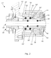
- Figure 2 shows a switchable coolant pump 10' comprising a clutch 40 connecting two independently rotatable rotors.
- Figure 1 shows a non-switchable coolant pump 10 with one single rotor.
- Both pump embodiments shown in figures 1 and 2 are provided with a first roller bearing 26;26' comprising a separate outer ring 50 which is directly fixed to a pump frame body 12.
- the outer ring 50 of the respective first roller bearing 26;26' is respectively fixed to the pump frame body 12 by a separate bearing fixation structure 52; 52'.
- the bearing fixation structure 52; 52' axially pushes the outer ring 50 of the first roller bearing 26;26' clearance-free against the pump frame body 12.
- the bearing fixation structure 52;52' is directly fixed to a transversal ring plane of the pump frame body 12.
- the bearing fixation structure 52;52' of both embodiments is made out of a single sheet metal body 56;56' and is provided with a cylinder part 58;58' housing the first rotor bearing 26;26', with a bearing fixation ring 60;60' projecting radially inwardly from the distal axial end of the cylinder part 58;58' and with a mounting flange 61;61' projecting radially outwardly from the proximal end of the cylinder part 58.
- the fixation structure sheet-metal body 56 is in axial direction minimally resilient so that the fixation of the outer ring 50 is tolerant with respect to mechanical inaccuracies.
- the pump frame body 12 is provided with a bearing centering structure 54 which radially centers the outer ring 50 of the first roller bearing 26;26'.
- the bearing centering structure 54 is realized by four centering noses 70 which force the outer ring 50 of the first roller bearing 26;26' into the center position without exerting relevant radial clamping forces,
- the axial length of the centering noses 70 is less than one fourth of the axial length of the outer bearing ring 50.
- the coolant pump 10 of figure 1 is provided with a pump wheel 20 which is fixed to a rotor shaft 18.
- the rotor shaft 18 is formed by one single rotor body 62 out of sheet metal.
- the rotor body 62 directly connects the pump wheel 20 with the separate driving wheel 32 and forms a connection means.
- the driving wheel 32 is driven by a driving belt which is driven by the internal combustion engine.
- the first roller bearing 26 comprises the outer bearing ring 50, a separate inner bearing ring 68 and rolling elements therebetween.
- the inner bearing ring 68 is press-fit onto the outer cylindrical surface of the rotor shaft 18.
- the ring-like clearance between the rotor shaft 18 and the housing 12 is sealed by a shaft sealing 24.
- the switchable coolant pump 10' of figure 2 is provided with a friction clutch 40 as a connecting means for connecting the pump wheel 20 with the driving wheel 32'. Therefore, the coolant pump 10' is provided with two independently rotating structure's and with a second roller bearing 28,
- the first roller bearing 26 supports a cylindrical rotor 66 of the driving wheel 32'.
- the second roller bearing 28 supports the rotor shaft 18 at the cylindrical rotor 66 of the driving wheel 32'.
- the inner bearing ring of the first roller bearing 26' is an integral part of the cylindrical rotor part 66 of the driving wheel 32'.
- the outer bearing ring of the second roller bearing 28 is integrally defined by the surface of the cylindrical rotor part 66 of the driving wheel 32',
- the inner bearing ring of the second roller bearing 28 is integrally defined by the rotor shaft 18.
- the axial length of the first roller bearing 26' is less than the axial length of the second roller bearing 28.
- the mechanical friction clutch 40 is provided with an axially shiftable friction ring 42 supported by the rotor shaft 18 and with an opposite friction ring 44 formed by a transversal ring-like surface of the driving wheel 32'. Inside the ring-like cavity which is enclosed by the U-shaped driving wheel 32' a stationary electromagnet 38 is arranged which is axially mounted to the bearing fixation structure 52'.
- the electromagnet 38 consists of a ring-like exciting coil 64 which generates a toroidal electromagnetic field when the electromagnet 38 is energized with DC. When the electromagnet 38 is energized, the clutch 40 is engaged.
Landscapes
- Engineering & Computer Science (AREA)
- Mechanical Engineering (AREA)
- General Engineering & Computer Science (AREA)
- Chemical & Material Sciences (AREA)
- Combustion & Propulsion (AREA)
- Structures Of Non-Positive Displacement Pumps (AREA)
- Rolling Contact Bearings (AREA)
- Details And Applications Of Rotary Liquid Pumps (AREA)
- Mounting Of Bearings Or Others (AREA)
- Applications Or Details Of Rotary Compressors (AREA)
- Reciprocating Pumps (AREA)
Abstract
Description
- The present invention refers to a mechanical combustion engine coolant pump for pumping a coolant for an internal combustion engine.
- A mechanical coolant pump is provided with a pump wheel and a rotatable rotor shaft being radially and axially supported by a roller bearing. The outer bearing ring of the roller bearing is normally press-fit into a cylindrical part of the stationary pump frame body. If the mechanical coolant pump is switchable with a friction clutch, another roller bearing is provided to support the rotatable driving wheel. If the driving wheel is directly supported by the stationary pump frame body, the outer ring of the roller bearing is press-fit into a cylindrical part of the pump frame body.
- The press-fitting of the outer bearing ring of the roller bearing into a cylindrical part of the pump frame body requires very precisely manufactured cylindrical press-fit surfaces of the corresponding parts. Additionally, the fixing procedure is complicated as well.
- It is an object of the present invention to provide a mechanical combustion engine coolant pump which can be manufactured and assembled cost easily and effective.
- This object is solved with a coolant mechanical coolant pump with the features of claim 1.
- Claim 1 is directed to a switchable and to a non-switchable mechanical coolant pump. The pump wheel is provided at a rotatable rotor shaft which is radially and axially supported. The rotatable driving wheel is driven by the combustion engine and is radially and axially supported as well. If the coolant pump is non-switchable, the pump wheel and the driving wheel both are directly supported by a first roller bearing. If the coolant pump is switchable by a friction clutch, the driving wheel can be directly supported by the first roller bearing at the pump frame body and the pump wheel rotor shaft can be directly supported by a second roller bearing at the driving wheel. In this case, the pump wheel is only indirectly supported by the first roller bearing at the pump frame bony.
- In other words, the first roller bearing is always supporting a rotatable part of the pump directly at the pump frame body, The rotatable part can be the rotor shaft or can be the driving wheel.
- The rotor shaft can permanency or non-permanently be connected with the driving wheel in a rotatably fixed manner by connecting means. The connecting means can be a stiff structure or can be a clutch, for example a friction clutch.
- The first roller bearing is provided with a separate outer ring which is directly fixed to the pump frame body. A separate bearing fixation structure is provided which is axially pushing the outer ring clearance-free against the pump frame body. The bearing fixation structure itself is directly fixed to the pump frame body by fixation means. The outer ring of the first roller bearing is not press-fit to the pump frame body but is axially pushed with a high pushing force against a suitable transversal surface of the pump frame body. As a consequence, the bearing fixation structure has to be at least minimally elastically.
- Since no precise press-fittable parts are needed anymore, the production of the respective parts is less cost-intensive. At least one press-fit process can be avoided so that the assembling is simplified significantly. In contrast to a press-fit connection, the fixation of the fixation structure at the pump frame body can be detachable. For the first roller bearing a pre-fabricated standard roller bearing can be used which is less expensive.
- Generally, the bearing fixation structure can be provided with centering means for precisely centering of the first roller bearing at the pump frame body. Preferably, the pump frame body can be provided with a bearing centering structure for radially centering the outer ring of the first roller bearing at the pump frame body. The centering structure can be realized by three or more centering noses, by a centering ring, by a centering notch etc.
- According to a preferred embodiment, the bearing fixation structure is a single sheet metal body with a cylinder part housing the first rotor bearing, with a bearing fixation ring projecting radially inwardly from the distal axial end of the cylinder part and with a mounting flange projecting radially outwardly from the proximal end of the cylinder part. The sheet metal body can be produced very cost-effective and is provided with the needed elastic properties. The form of the bearing fixation structure is similar to a pot with a central opening in the base and with an outward flange ring which is mounted to the pump frame body.
- Preferably, the connecting means connecting the rotor shaft and the driving wheel is a permanent connection so that the first roller bearing is directly engaged at the rotor shaft, The coolant pump is non-switchable. According to a preferred embodiment, one single rotor body is provided forming the rotor shaft and being directly engaged with the driving wheel. The rotor body can be a sheet metal body or can be manufactured out of solid material.
- According to a preferred embodiment of the invention, the connecting means connecting the rotor shaft with the driving wheel is a friction clutch actuated by an electromagnet. In this constitution, the first roller bearing is directly engaged with and is directly supporting the driving wheel. The rotor shaft is directly supported by a second roller bearing at a cylindrical rotor part of the driving wheel, The coolant pump is switchable. The friction clutch can be arranged at the distal end of the coolant pump, whereas the pump wheel is arranged at the other distal end of the coolant pump.
- Preferably, the electromagnet is a stationary circular ring coil being arranged axially distal of the first roller bearing, This is a very compact arrangement which allows to arrange a ring coil with a relatively high radial extension as close as possible to the clutch mechanism.
- Preferably, the electromagnet ring coil is directly fixed to the bearing fixation structure so that the bearing fixation structure has a second relevant function.
- In the figure's two embodiments of the invention are described in more detail with reference to the drawings, whereby
- figure 1
- shows a longitudinal cross-section of a non-switchable combustion engine coolant pump, and
- figure 2
- shows a longitudinal cross-section of a switchable combustion engine coolant pump.
- Both
figures 1 and2 show a mechanical combustionengine coolant pump 10, 10' for pumping a coolant, for example water, for and to an internal combustion engine.Figure 2 shows a switchable coolant pump 10' comprising aclutch 40 connecting two independently rotatable rotors.Figure 1 shows anon-switchable coolant pump 10 with one single rotor. - Both pump embodiments shown in
figures 1 and2 are provided with a first roller bearing 26;26' comprising a separateouter ring 50 which is directly fixed to apump frame body 12. Theouter ring 50 of the respective first roller bearing 26;26' is respectively fixed to thepump frame body 12 by a separatebearing fixation structure 52; 52'. Thebearing fixation structure 52; 52' axially pushes theouter ring 50 of the first roller bearing 26;26' clearance-free against thepump frame body 12. Thebearing fixation structure 52;52' is directly fixed to a transversal ring plane of thepump frame body 12. - The
bearing fixation structure 52;52' of both embodiments is made out of a singlesheet metal body 56;56' and is provided with acylinder part 58;58' housing the first rotor bearing 26;26', with abearing fixation ring 60;60' projecting radially inwardly from the distal axial end of thecylinder part 58;58' and with amounting flange 61;61' projecting radially outwardly from the proximal end of thecylinder part 58. The fixation structure sheet-metal body 56 is in axial direction minimally resilient so that the fixation of theouter ring 50 is tolerant with respect to mechanical inaccuracies. - The
pump frame body 12 is provided with a bearingcentering structure 54 which radially centers theouter ring 50 of the first roller bearing 26;26'. The bearingcentering structure 54 is realized by four centeringnoses 70 which force theouter ring 50 of the first roller bearing 26;26' into the center position without exerting relevant radial clamping forces, The axial length of the centeringnoses 70 is less than one fourth of the axial length of theouter bearing ring 50. - The
coolant pump 10 offigure 1 is provided with apump wheel 20 which is fixed to arotor shaft 18. Therotor shaft 18 is formed by onesingle rotor body 62 out of sheet metal. Therotor body 62 directly connects thepump wheel 20 with the separatedriving wheel 32 and forms a connection means. Thedriving wheel 32 is driven by a driving belt which is driven by the internal combustion engine. - The first roller bearing 26 comprises the
outer bearing ring 50, a separateinner bearing ring 68 and rolling elements therebetween. Theinner bearing ring 68 is press-fit onto the outer cylindrical surface of therotor shaft 18. The ring-like clearance between therotor shaft 18 and thehousing 12 is sealed by a shaft sealing 24. - In contrast to the
coolant pump 10 offigure 1 , the switchable coolant pump 10' offigure 2 is provided with a friction clutch 40 as a connecting means for connecting thepump wheel 20 with the driving wheel 32'. Therefore, the coolant pump 10' is provided with two independently rotating structure's and with asecond roller bearing 28, - The
first roller bearing 26 supports acylindrical rotor 66 of the driving wheel 32'. Thesecond roller bearing 28 supports therotor shaft 18 at thecylindrical rotor 66 of the driving wheel 32'. The inner bearing ring of the first roller bearing 26' is an integral part of thecylindrical rotor part 66 of the driving wheel 32'. - The outer bearing ring of the
second roller bearing 28 is integrally defined by the surface of thecylindrical rotor part 66 of the driving wheel 32', The inner bearing ring of thesecond roller bearing 28 is integrally defined by therotor shaft 18. The axial length of the first roller bearing 26' is less than the axial length of thesecond roller bearing 28. - The mechanical friction clutch 40 is provided with an axially
shiftable friction ring 42 supported by therotor shaft 18 and with anopposite friction ring 44 formed by a transversal ring-like surface of the driving wheel 32'. Inside the ring-like cavity which is enclosed by the U-shaped driving wheel 32' astationary electromagnet 38 is arranged which is axially mounted to the bearing fixation structure 52'. - The
electromagnet 38 consists of a ring-likeexciting coil 64 which generates a toroidal electromagnetic field when theelectromagnet 38 is energized with DC. When theelectromagnet 38 is energized, the clutch 40 is engaged.
Claims (10)
- Mechanical combustion engine coolant pump (10:10') for pumping a coolant for an internal combustion engine, comprising
a pump wheel (20) at a rotatable rotor shaft (18) being radially supported,
a rotatable driving wheel (32) being radially supported and being driven by the combustion engine,
means for connecting the rotor shaft (18) with the driving wheel (32) in a rotatably fixed manner,
whereby a first roller bearing (26:26') is directly radially supporting one of the two said rotatable means and is provided with a separate outer bearing ring (50) which is directly fixed to a pump frame body (12),
characterized by
a separate bearing fixation structure (52;52') axially pushing the outer ring (50) of the first roller bearing (26;26') clearance-free against the pump frame body (12), whereby the bearing fixation structure (52) is directly fixed to the pump frame body (12). - Mechanical combustion engine coolant pump (10,10') of claim 1, whereby the pump frame body (12) is provided with a bearing centering structure (54) for radially centering the outer ring (50) of the first roller bearing (26;26') at the pump frame body (12).
- Mechanical combustion engine coolant pump (10,10') of one of the preceding claims, whereby the bearing fixation structure (52;52') is a single sheet metal body (56;56') with a cylinder part (58;58') housing the first rotor bearing (26,26'), a bearing fixation ring (60;60') projecting radially inwardly from the distal axial end of the cylinder part (58;58') and a mounting flange (61;61') projecting radially outwardly from the proximal end of the cylinder part (58).
- Mechanical combustion engine coolant pump (10) of one of the preceding claims, whereby the connecting means is a permanent connection of the rotor shaft (18) with the driving wheel (32), the first roller bearing (26) being directly engaged with the rotor shaft (18).
- Mechanical combustion engine coolant pump (10) of claim 4, whereby one single rotor body (62) is provided forming the rotor shaft (18) and directly being engaged with the driving wheel (32).
- Mechanical combustion engine coolant pump (10) of claim 5, whereby the rotor body (62) is made of a single sheet metal piece and the driving wheel (32) is a separate part fixed to the rotor body (62).
- Mechanical combustion engine coolant pump (10') of one of the claims 1 to 3, whereby the connecting means is a friction clutch (40) actuated by an electromagnet (38), whereby the first roller bearing (26') is directly engaged with the driving wheel (32') and the rotor shaft (18') is directly supported by a second roller bearing (28) at a cylindrical rotor part (66) of the driving wheel (32').
- Mechanical combustion engine coolant pump (10') of claim 7, whereby the electromagnet (38) is a ring coif (64) being arranged axially distal of the first roller bearing (26').
- Mechanic combustion engine coolant pump (10') of claim 7 or 8, whereby the second roller bearing (28) is arranged radially inwardly of the first roller bearing (26').
- Mechanical combustion engine coolant pump (10') of one of the claims 7 to 9, whereby the electromagnet (38) is fixed to the bearing fixation structure (52').
Priority Applications (9)
| Application Number | Priority Date | Filing Date | Title |
|---|---|---|---|
| AT10150437T ATE540209T1 (en) | 2010-01-11 | 2010-01-11 | MECHANICAL COMBUSTION ENGINE COOLANT PUMP |
| EP10150437A EP2351919B1 (en) | 2010-01-11 | 2010-01-11 | Mechanical combustion engine coolant pump |
| ES10150437T ES2378645T3 (en) | 2010-01-11 | 2010-01-11 | Mechanical pump for cooling a combustion engine |
| MX2012008037A MX2012008037A (en) | 2010-01-11 | 2010-08-24 | Mechanical combustion engine coolant pump. |
| US13/521,056 US8920141B2 (en) | 2010-01-11 | 2010-08-24 | Mechanical combustion engine coolant pump |
| CN201080065322.4A CN102791985B (en) | 2010-01-11 | 2010-08-24 | Mechanical combustion engine coolant pump |
| JP2012548359A JP5665881B2 (en) | 2010-01-11 | 2010-08-24 | Mechanical combustion engine coolant pump |
| PCT/EP2010/062331 WO2011082841A1 (en) | 2010-01-11 | 2010-08-24 | Mechanical combustion engine coolant pump |
| BR112012016962A BR112012016962A2 (en) | 2010-01-11 | 2010-08-24 | mechanical combustion engine cooling pump |
Applications Claiming Priority (1)
| Application Number | Priority Date | Filing Date | Title |
|---|---|---|---|
| EP10150437A EP2351919B1 (en) | 2010-01-11 | 2010-01-11 | Mechanical combustion engine coolant pump |
Publications (2)
| Publication Number | Publication Date |
|---|---|
| EP2351919A1 true EP2351919A1 (en) | 2011-08-03 |
| EP2351919B1 EP2351919B1 (en) | 2012-01-04 |
Family
ID=42339280
Family Applications (1)
| Application Number | Title | Priority Date | Filing Date |
|---|---|---|---|
| EP10150437A Active EP2351919B1 (en) | 2010-01-11 | 2010-01-11 | Mechanical combustion engine coolant pump |
Country Status (9)
| Country | Link |
|---|---|
| US (1) | US8920141B2 (en) |
| EP (1) | EP2351919B1 (en) |
| JP (1) | JP5665881B2 (en) |
| CN (1) | CN102791985B (en) |
| AT (1) | ATE540209T1 (en) |
| BR (1) | BR112012016962A2 (en) |
| ES (1) | ES2378645T3 (en) |
| MX (1) | MX2012008037A (en) |
| WO (1) | WO2011082841A1 (en) |
Cited By (1)
| Publication number | Priority date | Publication date | Assignee | Title |
|---|---|---|---|---|
| WO2013190002A1 (en) * | 2012-06-19 | 2013-12-27 | C & S Sonderfahrzeuge GmbH | Auxiliary unit for controlling one or more hydraulic drives |
Families Citing this family (7)
| Publication number | Priority date | Publication date | Assignee | Title |
|---|---|---|---|---|
| US9927017B2 (en) * | 2015-04-17 | 2018-03-27 | Aktiebolaget Skf | Sheave for guiding rope in an industrial machine |
| AR112221A1 (en) | 2017-07-05 | 2019-10-02 | Fmc Corp | FUNGICIDE OXADIAZOLES, COMPOSITION THAT INCLUDE THEM AND A METHOD TO CONTROL PHYTO DISEASES THAT USE THEM |
| DE102018112896A1 (en) * | 2018-05-30 | 2019-12-05 | HWC GmbH & Co. KG | rotary pump |
| BR112021020232A2 (en) | 2019-04-08 | 2021-12-07 | Pi Industries Ltd | Innovative Oxadiazole Compounds to Control or Prevent Phytopathogenic Fungi |
| EP3953353A1 (en) | 2019-04-08 | 2022-02-16 | PI Industries Ltd. | Novel oxadiazole compounds for controlling or preventing phytopathogenic fungi |
| CA3131995A1 (en) | 2019-04-08 | 2020-10-15 | Pi Industries Limited | Novel oxadiazole compounds for controlling or preventing phytopathogenic fungi |
| WO2025099582A1 (en) * | 2023-11-10 | 2025-05-15 | Baruffaldi S.P.A. | Operating device for operating a recirculating pump with multi-level bearing fixed to a rotor |
Citations (4)
| Publication number | Priority date | Publication date | Assignee | Title |
|---|---|---|---|---|
| US3838899A (en) * | 1973-07-27 | 1974-10-01 | Gen Motors Corp | Axially preloaded bearing assembly |
| DE3716098A1 (en) * | 1987-05-14 | 1988-11-24 | Skf Gmbh | Drive device for pumps or the like |
| EP1188931A2 (en) * | 2000-09-19 | 2002-03-20 | Aisin Seiki Kabushiki Kaisha | Water pump |
| EP1696111A2 (en) * | 2005-01-26 | 2006-08-30 | Baruffaldi S.p.A. | Device for transmitting the rotating movement to a driven shaft, in particular for fluid recirculating pumps |
Family Cites Families (10)
| Publication number | Priority date | Publication date | Assignee | Title |
|---|---|---|---|---|
| JPS62108595U (en) * | 1985-12-26 | 1987-07-10 | ||
| IT1219755B (en) * | 1987-05-14 | 1990-05-24 | Skf Gmbh | DRIVE DEVICE FOR PUMPS OR SIMILAR |
| JPH0629517Y2 (en) * | 1988-08-31 | 1994-08-10 | 株式会社ユニシアジェックス | Water pump |
| JP3675321B2 (en) * | 2000-09-19 | 2005-07-27 | アイシン精機株式会社 | Water pump |
| JP2002155893A (en) | 2000-11-17 | 2002-05-31 | Aisin Seiki Co Ltd | Water pump |
| EP1353051B1 (en) * | 2002-04-08 | 2007-07-18 | Baruffaldi S.p.A. | Device for controlling the actuating shaft of means for recirculating a cooling fluid in vehicle engines |
| JP2004052669A (en) * | 2002-07-19 | 2004-02-19 | Aisin Seiki Co Ltd | Water pump |
| JP2004150300A (en) * | 2002-10-29 | 2004-05-27 | Aisin Seiki Co Ltd | Water pump |
| US7922464B2 (en) * | 2006-04-12 | 2011-04-12 | Aisin Seiki Kabushiki Kaisha | Magnetic drive pump |
| FR2901843B1 (en) | 2006-05-30 | 2008-08-01 | Snr Roulements Sa | BELT DRIVE MECHANISM |
-
2010
- 2010-01-11 AT AT10150437T patent/ATE540209T1/en active
- 2010-01-11 ES ES10150437T patent/ES2378645T3/en active Active
- 2010-01-11 EP EP10150437A patent/EP2351919B1/en active Active
- 2010-08-24 MX MX2012008037A patent/MX2012008037A/en not_active Application Discontinuation
- 2010-08-24 BR BR112012016962A patent/BR112012016962A2/en not_active IP Right Cessation
- 2010-08-24 US US13/521,056 patent/US8920141B2/en not_active Expired - Fee Related
- 2010-08-24 WO PCT/EP2010/062331 patent/WO2011082841A1/en not_active Ceased
- 2010-08-24 CN CN201080065322.4A patent/CN102791985B/en not_active Expired - Fee Related
- 2010-08-24 JP JP2012548359A patent/JP5665881B2/en not_active Expired - Fee Related
Patent Citations (4)
| Publication number | Priority date | Publication date | Assignee | Title |
|---|---|---|---|---|
| US3838899A (en) * | 1973-07-27 | 1974-10-01 | Gen Motors Corp | Axially preloaded bearing assembly |
| DE3716098A1 (en) * | 1987-05-14 | 1988-11-24 | Skf Gmbh | Drive device for pumps or the like |
| EP1188931A2 (en) * | 2000-09-19 | 2002-03-20 | Aisin Seiki Kabushiki Kaisha | Water pump |
| EP1696111A2 (en) * | 2005-01-26 | 2006-08-30 | Baruffaldi S.p.A. | Device for transmitting the rotating movement to a driven shaft, in particular for fluid recirculating pumps |
Cited By (1)
| Publication number | Priority date | Publication date | Assignee | Title |
|---|---|---|---|---|
| WO2013190002A1 (en) * | 2012-06-19 | 2013-12-27 | C & S Sonderfahrzeuge GmbH | Auxiliary unit for controlling one or more hydraulic drives |
Also Published As
| Publication number | Publication date |
|---|---|
| US20120321487A1 (en) | 2012-12-20 |
| WO2011082841A1 (en) | 2011-07-14 |
| EP2351919B1 (en) | 2012-01-04 |
| BR112012016962A2 (en) | 2016-04-12 |
| US8920141B2 (en) | 2014-12-30 |
| JP5665881B2 (en) | 2015-02-04 |
| JP2013516578A (en) | 2013-05-13 |
| ATE540209T1 (en) | 2012-01-15 |
| CN102791985A (en) | 2012-11-21 |
| CN102791985B (en) | 2015-05-20 |
| ES2378645T3 (en) | 2012-04-16 |
| MX2012008037A (en) | 2012-08-01 |
Similar Documents
| Publication | Publication Date | Title |
|---|---|---|
| EP2351919B1 (en) | Mechanical combustion engine coolant pump | |
| US7986068B2 (en) | Motor | |
| CN102171495B (en) | Divided wheel | |
| US10323642B2 (en) | Pump motor with a fixed bearing | |
| US10590948B2 (en) | Adapter device for attaching a cooling fan to a motor and cooling fan module for an automotive cooling system | |
| US20160079828A1 (en) | Bearing arrangement in an electric motor | |
| JP2012520431A (en) | Thermally isolated bearing device | |
| EP2597761A3 (en) | Electric motor and electric unit including the same | |
| US20110203398A1 (en) | Divided Toothed Wheel | |
| EP1873892A3 (en) | Brushless motor | |
| CN103867547B (en) | Torsional and axial fixing of a rolling bearing | |
| US20110223009A1 (en) | Pump assembly | |
| EP2351918B1 (en) | Mechanical combustion engine coolant pump | |
| US20180163723A1 (en) | Electric pump | |
| CN105386920A (en) | Starting device for internal combustion engine | |
| CA2454877A1 (en) | External rotor motor | |
| US11677285B2 (en) | Outer rotor type motor capable of improving withstand load performance in relation to external load and lifespan | |
| US20120068559A1 (en) | Rotating shaft support apparatus and magnetic motor having the same | |
| JP2014126048A (en) | Gear and electric motor using gear | |
| JP3239642U (en) | Structure of rotary motor | |
| KR20160127673A (en) | Rotor arrangement for a vacuum pump | |
| JP6554043B2 (en) | Connection structure between drive shaft member and driven shaft member | |
| GB2334629A (en) | Thrust ring in an electric motor | |
| JP2005180505A (en) | Positioning device | |
| JP2007236144A (en) | Motor |
Legal Events
| Date | Code | Title | Description |
|---|---|---|---|
| PUAI | Public reference made under article 153(3) epc to a published international application that has entered the european phase |
Free format text: ORIGINAL CODE: 0009012 |
|
| AK | Designated contracting states |
Kind code of ref document: A1 Designated state(s): AT BE BG CH CY CZ DE DK EE ES FI FR GB GR HR HU IE IS IT LI LT LU LV MC MK MT NL NO PL PT RO SE SI SK SM TR |
|
| AX | Request for extension of the european patent |
Extension state: AL BA RS |
|
| 17P | Request for examination filed |
Effective date: 20110714 |
|
| GRAP | Despatch of communication of intention to grant a patent |
Free format text: ORIGINAL CODE: EPIDOSNIGR1 |
|
| GRAS | Grant fee paid |
Free format text: ORIGINAL CODE: EPIDOSNIGR3 |
|
| GRAA | (expected) grant |
Free format text: ORIGINAL CODE: 0009210 |
|
| AK | Designated contracting states |
Kind code of ref document: B1 Designated state(s): AT BE BG CH CY CZ DE DK EE ES FI FR GB GR HR HU IE IS IT LI LT LU LV MC MK MT NL NO PL PT RO SE SI SK SM TR |
|
| REG | Reference to a national code |
Ref country code: GB Ref legal event code: FG4D |
|
| REG | Reference to a national code |
Ref country code: CH Ref legal event code: EP |
|
| REG | Reference to a national code |
Ref country code: AT Ref legal event code: REF Ref document number: 540209 Country of ref document: AT Kind code of ref document: T Effective date: 20120115 |
|
| REG | Reference to a national code |
Ref country code: IE Ref legal event code: FG4D |
|
| REG | Reference to a national code |
Ref country code: DE Ref legal event code: R096 Ref document number: 602010000587 Country of ref document: DE Effective date: 20120308 |
|
| REG | Reference to a national code |
Ref country code: SE Ref legal event code: TRGR |
|
| REG | Reference to a national code |
Ref country code: ES Ref legal event code: FG2A Ref document number: 2378645 Country of ref document: ES Kind code of ref document: T3 Effective date: 20120416 |
|
| REG | Reference to a national code |
Ref country code: NL Ref legal event code: VDEP Effective date: 20120104 |
|
| PG25 | Lapsed in a contracting state [announced via postgrant information from national office to epo] |
Ref country code: SI Free format text: LAPSE BECAUSE OF FAILURE TO SUBMIT A TRANSLATION OF THE DESCRIPTION OR TO PAY THE FEE WITHIN THE PRESCRIBED TIME-LIMIT Effective date: 20120104 |
|
| LTIE | Lt: invalidation of european patent or patent extension |
Effective date: 20120104 |
|
| PG25 | Lapsed in a contracting state [announced via postgrant information from national office to epo] |
Ref country code: BG Free format text: LAPSE BECAUSE OF FAILURE TO SUBMIT A TRANSLATION OF THE DESCRIPTION OR TO PAY THE FEE WITHIN THE PRESCRIBED TIME-LIMIT Effective date: 20120404 Ref country code: BE Free format text: LAPSE BECAUSE OF FAILURE TO SUBMIT A TRANSLATION OF THE DESCRIPTION OR TO PAY THE FEE WITHIN THE PRESCRIBED TIME-LIMIT Effective date: 20120104 Ref country code: NL Free format text: LAPSE BECAUSE OF FAILURE TO SUBMIT A TRANSLATION OF THE DESCRIPTION OR TO PAY THE FEE WITHIN THE PRESCRIBED TIME-LIMIT Effective date: 20120104 Ref country code: NO Free format text: LAPSE BECAUSE OF FAILURE TO SUBMIT A TRANSLATION OF THE DESCRIPTION OR TO PAY THE FEE WITHIN THE PRESCRIBED TIME-LIMIT Effective date: 20120404 Ref country code: IS Free format text: LAPSE BECAUSE OF FAILURE TO SUBMIT A TRANSLATION OF THE DESCRIPTION OR TO PAY THE FEE WITHIN THE PRESCRIBED TIME-LIMIT Effective date: 20120504 Ref country code: HR Free format text: LAPSE BECAUSE OF FAILURE TO SUBMIT A TRANSLATION OF THE DESCRIPTION OR TO PAY THE FEE WITHIN THE PRESCRIBED TIME-LIMIT Effective date: 20120104 Ref country code: LT Free format text: LAPSE BECAUSE OF FAILURE TO SUBMIT A TRANSLATION OF THE DESCRIPTION OR TO PAY THE FEE WITHIN THE PRESCRIBED TIME-LIMIT Effective date: 20120104 |
|
| PG25 | Lapsed in a contracting state [announced via postgrant information from national office to epo] |
Ref country code: PL Free format text: LAPSE BECAUSE OF FAILURE TO SUBMIT A TRANSLATION OF THE DESCRIPTION OR TO PAY THE FEE WITHIN THE PRESCRIBED TIME-LIMIT Effective date: 20120104 Ref country code: GR Free format text: LAPSE BECAUSE OF FAILURE TO SUBMIT A TRANSLATION OF THE DESCRIPTION OR TO PAY THE FEE WITHIN THE PRESCRIBED TIME-LIMIT Effective date: 20120405 Ref country code: PT Free format text: LAPSE BECAUSE OF FAILURE TO SUBMIT A TRANSLATION OF THE DESCRIPTION OR TO PAY THE FEE WITHIN THE PRESCRIBED TIME-LIMIT Effective date: 20120504 Ref country code: MC Free format text: LAPSE BECAUSE OF NON-PAYMENT OF DUE FEES Effective date: 20120131 Ref country code: LV Free format text: LAPSE BECAUSE OF FAILURE TO SUBMIT A TRANSLATION OF THE DESCRIPTION OR TO PAY THE FEE WITHIN THE PRESCRIBED TIME-LIMIT Effective date: 20120104 Ref country code: FI Free format text: LAPSE BECAUSE OF FAILURE TO SUBMIT A TRANSLATION OF THE DESCRIPTION OR TO PAY THE FEE WITHIN THE PRESCRIBED TIME-LIMIT Effective date: 20120104 |
|
| REG | Reference to a national code |
Ref country code: AT Ref legal event code: MK05 Ref document number: 540209 Country of ref document: AT Kind code of ref document: T Effective date: 20120104 |
|
| PG25 | Lapsed in a contracting state [announced via postgrant information from national office to epo] |
Ref country code: CY Free format text: LAPSE BECAUSE OF FAILURE TO SUBMIT A TRANSLATION OF THE DESCRIPTION OR TO PAY THE FEE WITHIN THE PRESCRIBED TIME-LIMIT Effective date: 20120104 |
|
| REG | Reference to a national code |
Ref country code: IE Ref legal event code: MM4A |
|
| PG25 | Lapsed in a contracting state [announced via postgrant information from national office to epo] |
Ref country code: DK Free format text: LAPSE BECAUSE OF FAILURE TO SUBMIT A TRANSLATION OF THE DESCRIPTION OR TO PAY THE FEE WITHIN THE PRESCRIBED TIME-LIMIT Effective date: 20120104 Ref country code: EE Free format text: LAPSE BECAUSE OF FAILURE TO SUBMIT A TRANSLATION OF THE DESCRIPTION OR TO PAY THE FEE WITHIN THE PRESCRIBED TIME-LIMIT Effective date: 20120104 Ref country code: CZ Free format text: LAPSE BECAUSE OF FAILURE TO SUBMIT A TRANSLATION OF THE DESCRIPTION OR TO PAY THE FEE WITHIN THE PRESCRIBED TIME-LIMIT Effective date: 20120104 Ref country code: RO Free format text: LAPSE BECAUSE OF FAILURE TO SUBMIT A TRANSLATION OF THE DESCRIPTION OR TO PAY THE FEE WITHIN THE PRESCRIBED TIME-LIMIT Effective date: 20120104 |
|
| PLBE | No opposition filed within time limit |
Free format text: ORIGINAL CODE: 0009261 |
|
| STAA | Information on the status of an ep patent application or granted ep patent |
Free format text: STATUS: NO OPPOSITION FILED WITHIN TIME LIMIT |
|
| PG25 | Lapsed in a contracting state [announced via postgrant information from national office to epo] |
Ref country code: SK Free format text: LAPSE BECAUSE OF FAILURE TO SUBMIT A TRANSLATION OF THE DESCRIPTION OR TO PAY THE FEE WITHIN THE PRESCRIBED TIME-LIMIT Effective date: 20120104 |
|
| 26N | No opposition filed |
Effective date: 20121005 |
|
| PG25 | Lapsed in a contracting state [announced via postgrant information from national office to epo] |
Ref country code: IE Free format text: LAPSE BECAUSE OF NON-PAYMENT OF DUE FEES Effective date: 20120111 Ref country code: AT Free format text: LAPSE BECAUSE OF FAILURE TO SUBMIT A TRANSLATION OF THE DESCRIPTION OR TO PAY THE FEE WITHIN THE PRESCRIBED TIME-LIMIT Effective date: 20120104 |
|
| REG | Reference to a national code |
Ref country code: DE Ref legal event code: R097 Ref document number: 602010000587 Country of ref document: DE Effective date: 20121005 |
|
| PG25 | Lapsed in a contracting state [announced via postgrant information from national office to epo] |
Ref country code: MK Free format text: LAPSE BECAUSE OF FAILURE TO SUBMIT A TRANSLATION OF THE DESCRIPTION OR TO PAY THE FEE WITHIN THE PRESCRIBED TIME-LIMIT Effective date: 20120104 |
|
| PG25 | Lapsed in a contracting state [announced via postgrant information from national office to epo] |
Ref country code: MT Free format text: LAPSE BECAUSE OF FAILURE TO SUBMIT A TRANSLATION OF THE DESCRIPTION OR TO PAY THE FEE WITHIN THE PRESCRIBED TIME-LIMIT Effective date: 20120104 |
|
| PG25 | Lapsed in a contracting state [announced via postgrant information from national office to epo] |
Ref country code: TR Free format text: LAPSE BECAUSE OF FAILURE TO SUBMIT A TRANSLATION OF THE DESCRIPTION OR TO PAY THE FEE WITHIN THE PRESCRIBED TIME-LIMIT Effective date: 20120104 |
|
| PGFP | Annual fee paid to national office [announced via postgrant information from national office to epo] |
Ref country code: SE Payment date: 20140123 Year of fee payment: 5 |
|
| PG25 | Lapsed in a contracting state [announced via postgrant information from national office to epo] |
Ref country code: LU Free format text: LAPSE BECAUSE OF NON-PAYMENT OF DUE FEES Effective date: 20120111 Ref country code: SM Free format text: LAPSE BECAUSE OF FAILURE TO SUBMIT A TRANSLATION OF THE DESCRIPTION OR TO PAY THE FEE WITHIN THE PRESCRIBED TIME-LIMIT Effective date: 20120104 |
|
| PGFP | Annual fee paid to national office [announced via postgrant information from national office to epo] |
Ref country code: ES Payment date: 20140122 Year of fee payment: 5 |
|
| PG25 | Lapsed in a contracting state [announced via postgrant information from national office to epo] |
Ref country code: HU Free format text: LAPSE BECAUSE OF FAILURE TO SUBMIT A TRANSLATION OF THE DESCRIPTION OR TO PAY THE FEE WITHIN THE PRESCRIBED TIME-LIMIT Effective date: 20100111 |
|
| REG | Reference to a national code |
Ref country code: CH Ref legal event code: PL |
|
| PG25 | Lapsed in a contracting state [announced via postgrant information from national office to epo] |
Ref country code: CH Free format text: LAPSE BECAUSE OF NON-PAYMENT OF DUE FEES Effective date: 20140131 Ref country code: LI Free format text: LAPSE BECAUSE OF NON-PAYMENT OF DUE FEES Effective date: 20140131 |
|
| REG | Reference to a national code |
Ref country code: SE Ref legal event code: EUG |
|
| GBPC | Gb: european patent ceased through non-payment of renewal fee |
Effective date: 20150111 |
|
| PG25 | Lapsed in a contracting state [announced via postgrant information from national office to epo] |
Ref country code: GB Free format text: LAPSE BECAUSE OF NON-PAYMENT OF DUE FEES Effective date: 20150111 |
|
| PG25 | Lapsed in a contracting state [announced via postgrant information from national office to epo] |
Ref country code: SE Free format text: LAPSE BECAUSE OF NON-PAYMENT OF DUE FEES Effective date: 20150112 |
|
| REG | Reference to a national code |
Ref country code: FR Ref legal event code: PLFP Year of fee payment: 7 |
|
| REG | Reference to a national code |
Ref country code: ES Ref legal event code: FD2A Effective date: 20160226 |
|
| PG25 | Lapsed in a contracting state [announced via postgrant information from national office to epo] |
Ref country code: ES Free format text: LAPSE BECAUSE OF NON-PAYMENT OF DUE FEES Effective date: 20150112 |
|
| REG | Reference to a national code |
Ref country code: FR Ref legal event code: PLFP Year of fee payment: 8 |
|
| REG | Reference to a national code |
Ref country code: FR Ref legal event code: PLFP Year of fee payment: 9 |
|
| PGFP | Annual fee paid to national office [announced via postgrant information from national office to epo] |
Ref country code: GB Payment date: 20190123 Year of fee payment: 18 Ref country code: IT Payment date: 20190121 Year of fee payment: 10 |
|
| REG | Reference to a national code |
Ref country code: DE Ref legal event code: R082 Ref document number: 602010000587 Country of ref document: DE Representative=s name: TERPATENT PARTGMBB, DE Ref country code: DE Ref legal event code: R082 Ref document number: 602010000587 Country of ref document: DE Representative=s name: TERPATENT PATENTANWAELTE TER SMITTEN EBERLEIN-, DE |
|
| PG25 | Lapsed in a contracting state [announced via postgrant information from national office to epo] |
Ref country code: FR Free format text: LAPSE BECAUSE OF NON-PAYMENT OF DUE FEES Effective date: 20200131 |
|
| PG25 | Lapsed in a contracting state [announced via postgrant information from national office to epo] |
Ref country code: IT Free format text: LAPSE BECAUSE OF NON-PAYMENT OF DUE FEES Effective date: 20200111 |
|
| REG | Reference to a national code |
Ref country code: DE Ref legal event code: R082 Ref document number: 602010000587 Country of ref document: DE |
|
| PGFP | Annual fee paid to national office [announced via postgrant information from national office to epo] |
Ref country code: DE Payment date: 20260121 Year of fee payment: 17 |