JP3239642U - Structure of rotary motor - Google Patents
Structure of rotary motor Download PDFInfo
- Publication number
- JP3239642U JP3239642U JP2022002899U JP2022002899U JP3239642U JP 3239642 U JP3239642 U JP 3239642U JP 2022002899 U JP2022002899 U JP 2022002899U JP 2022002899 U JP2022002899 U JP 2022002899U JP 3239642 U JP3239642 U JP 3239642U
- Authority
- JP
- Japan
- Prior art keywords
- rotary motor
- body portion
- outer ring
- bearing
- annular
- Prior art date
- Legal status (The legal status is an assumption and is not a legal conclusion. Google has not performed a legal analysis and makes no representation as to the accuracy of the status listed.)
- Active
Links
Images

Landscapes
- Connection Of Motors, Electrical Generators, Mechanical Devices, And The Like (AREA)
Abstract

【課題】簡素化された部材で構成され、全体の高さの大幅な削減を達成することができ、狭小スペースの動作環境において使用することが可能な回転モータの構造を提供する。
【解決手段】回転モータの構造は、主な技術的特徴として、軸受40と回転モータの固定子20ハウジングと回転子30ハウジングを直接結合させて、固定子ハウジングと回転子ハウジングにより軸受を直接位置決めすると同時に、軸受によって回転子ハウジングに回転における支持を提供する。
【選択図】図3
A structure of a rotary motor is provided, which is composed of simplified members, achieves a significant reduction in overall height, and can be used in a narrow space operating environment.
The main technical feature of the structure of the rotary motor is that the bearing (40) is directly coupled with the housing of the stator (20) and the rotor (30) of the rotary motor, and the bearing is directly positioned by the stator housing and the rotor housing. At the same time, the bearings provide rotational support to the rotor housing.
[Selection drawing] Fig. 3
Description
本考案はモータ技術に関し、特に回転モータの構造に関する。 TECHNICAL FIELD The present invention relates to motor technology, and more particularly to the structure of rotary motors.
可動子と固定子との間の磁場の相互作用を利用することで回転運動を達成するモータ技術において、軸受によって回転部材に適当な支持を提供することにより、回転運動の安定性が確保され、部材同士の摩擦が減り、動作効率が高まり、耐用年数が延びるなどの効果については、公知で常用されている既知技術に属する。 In motor technology that achieves rotary motion by utilizing the interaction of magnetic fields between a mover and a stator, the stability of the rotary motion is ensured by providing adequate support to the rotating member by means of bearings, Effects such as reduced friction between members, increased operating efficiency, and extended service life belong to the well-known and commonly used known technologies.
従来技術の未だ完成されていない軸受部材と回転部材の結合手段がネックとなっているため、モータの全体的な構成も未だに最もシンプルなレベルには達していない。例えば、特許文献1が開示するモータの技術では、軸受部材が回転部材と固定部材の間に挟み込まれているが、同時に適当な抑圧部材によって軸受部材の軸方向の両端から抑圧して軸受部材の所在位置の安定性を確保し、作動過程中の軸受部材の滑脱を回避しなければならない。このようにした場合、モータ全体の厚みを減らすことが難しく、利用スペースに対する要求が高い動作環境では使用することができない。 The overall structure of the motor is still far from the simplest level because of the imperfect coupling means of the bearing member and the rotating member of the prior art. For example, in the motor technology disclosed in Patent Document 1, a bearing member is sandwiched between a rotating member and a fixed member. Positional stability must be ensured and slippage of the bearing member during the operation process must be avoided. In this case, it is difficult to reduce the thickness of the entire motor, and it cannot be used in operating environments with high demands on available space.
本考案の主な目的は、簡素化された部材で構成され、モータ全体の高さの大幅な削減を達成することができ、狭小スペースの動作環境において使用することが可能な、回転モータの構造を提供することを主な目的としている。 The main purpose of the present invention is the structure of a rotary motor, which is composed of simplified members, can achieve a significant reduction in the overall height of the motor, and can be used in a narrow space operating environment. The main purpose is to provide
上述の目的を達成するために、本考案が提供する回転モータの構造は、主な技術的特徴として、軸受と回転モータの固定子ハウジングと回転子ハウジングを直接結合させて、固定子ハウジングと回転子ハウジングにより軸受を直接位置決めすると同時に、軸受によって回転子ハウジングに回転における支持を提供する。 To achieve the above objectives, the rotary motor structure provided by the present invention has the main technical feature that the bearing is directly coupled with the stator housing and the rotor housing of the rotary motor so that the stator housing and the rotary motor are connected. The daughter housing directly positions the bearings while the bearings provide rotational support to the rotor housing.
技術的内容について言えば、回転モータの構造は、第1部材、第2部材及び軸受を含む。第1部材は、環状を呈する第1本体部と、第1本体部の片側の円環面によって定義される第1担持面と、第1本体部から半径方向に内側に向かって延在する第1結合部と、を有する。第2部材は、環状を呈し、第1本体部と同軸である第2本体部と、第1担持面と相対し且つ互いに離されており、第2本体部の片側の円環面によって定義される第2担持面と、第2本体部に位置する第2結合部と、を有する。軸受は、第2本体部の内側で同軸に位置しており、外環と内環を有し、外環によって第2結合部と接続固定され、且つ外環の軸方向の一端部上に位置する第1端は第1結合部と離されており、内環の軸方向の一端部上に位置する第1端が第1結合部と接続固定され、且つ内環の軸方向の他端部上に位置する第2端と、外環の軸方向の他端部上に位置する第2端とは互いに半径方向の異なる平面上に位置する。 In terms of technical content, the structure of a rotary motor includes a first member, a second member and a bearing. The first member has a first body portion having an annular shape, a first bearing surface defined by a toric surface on one side of the first body portion, and a second bearing surface extending radially inwardly from the first body portion. 1 joint. The second member has an annular shape and is coaxial with the first body portion and is opposed to and spaced apart from the first bearing surface and is defined by the torus on one side of the second body portion. and a second coupling portion located on the second body portion. The bearing is coaxially positioned inside the second body portion, has an outer ring and an inner ring, is fixedly connected to the second coupling portion by the outer ring, and is positioned on one axial end of the outer ring. The first end located on one axial end of the inner ring is connected and fixed to the first coupling portion, and the other axial end of the inner ring The second end located above and the second end located on the other axial end of the outer ring are located on different planes in the radial direction.
これにより、第1部材と第2部材を回転モータの固定子ハウジングと回転子ハウジングとすると同時に、軸受を固定子ハウジングと回転子ハウジングに直接結合させることができ、既知技術のように外部の抑圧部材によって軸受をさらに位置決めする必要がなく、全体的な構成要素の数が減り、部材の積み重ねが及ぼす精度への影響が低減され、モータの全体の体積が縮小される。 This allows the first and second members to be the stator and rotor housings of a rotary motor, while the bearings can be coupled directly to the stator and rotor housings, without external restraint as is known in the art. No additional positioning of the bearings by members is required, the overall component count is reduced, the accuracy impact of member stacking is reduced, and the overall volume of the motor is reduced.
さらに、軸受は、外環上に設けられて外部の可動部材と相接するのに用いられる第3結合部をさらに含むことができ、これにより外部の可動部材を軸受に直接結合することができ、既知技術のように伝動部材や摩擦を減らす転動部材をさらに設置する必要がなく、これによりモータを使用する際に狭小スペースのニーズを満たせるようにすることができる。 Furthermore, the bearing may further include a third coupling portion provided on the outer ring and used to contact the external movable member, thereby directly coupling the external movable member to the bearing. , there is no need to additionally install a transmission member or a friction-reducing rolling member as in the known art, which makes it possible to meet the needs of small spaces when using the motor.
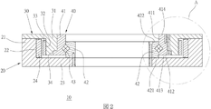
図1~図3を参照して、本考案の好ましい実施例中で提供する回転モータの改良構造(10)は、主に第1部材(20)、第2部材(30)及び軸受(40)を含む。 1-3, the improved structure (10) of rotary motor provided in the preferred embodiment of the present invention mainly comprises a first member (20), a second member (30) and a bearing (40). including.
第1部材(20)は回転モータの固定子とされ、構造においては、環状を呈し、且つ軸方向に沿って適当な長さで延在する第1本体部(21)と、第1本体部(21)の内側円環面によって定義される第1担持面(22)と、第1本体部(21)の軸方向の一端から半径方向に内側に向かって適当な長さで延在するリング板状の第1結合部(23)と、第1担持面(22)上に設置される複数のコイル(24)と、を有する。 The first member (20) is a stator of a rotary motor, and is structurally composed of a first main body (21) having an annular shape and extending along the axial direction with an appropriate length, and a first main body (21). a first bearing surface (22) defined by the inner toric surface of (21) and a ring extending radially inwardly from one axial end of the first body portion (21) a suitable length; It has a plate-like first coupling part (23) and a plurality of coils (24) mounted on the first bearing surface (22).
第2部材(30)は回転モータの回転子とされ、それは、環状を呈し、且つ軸方向に沿って適当な長さで延在し、第1本体部(21)の内側に同軸に位置する、第2本体部(31)と、第2担持面(32)であって、第2本体部(31)の外周円環面によって定義され、第1担持面(22)と相対し且つ適当な距離で離されており、複数の片状の磁石(33)が第2担持面(32)上にそれぞれ固定接続され、且つコイル(24)と離されている、第2担持面(32)と、第2本体部(31)に設けられた、第2結合部(34)と、を含む。 The second member (30) is the rotor of the rotary motor, which has an annular shape and extends for a suitable length along the axial direction and is coaxially positioned inside the first body (21). , a second body portion (31) and a second bearing surface (32) defined by the outer circumferential torus of the second body portion (31), opposite the first bearing surface (22) and a suitable a second bearing surface (32) separated by a distance, wherein a plurality of strip magnets (33) are each fixedly connected on the second bearing surface (32) and separated from the coil (24); , and a second coupling portion (34) provided on the second body portion (31).
さらに、第2結合部(34)はノッチであり、第2本体部(31)の軸方向の一端部上に凹設されており、且つ第2本体部(31)の環状形に沿って延在して成るものである。 Further, the second coupling portion (34) is a notch recessed on one axial end of the second body portion (31) and extending along the annular shape of the second body portion (31). It exists and consists.
軸受(40)は、外環(41)、内環(42)、及び外環(41)と内環(42)の間に位置する複数の転動部材(43)を含み、そのうち、外環(41)は、外側円環面が第2本体部(31)の内側円環面上に同軸で当接し、且つ第2結合部(23)と相接しており、内環(42)は、軸方向の一端部上に位置する第1端(421)が第1結合部(23)上に当接しており、且つこれにより第1部材(20)と接続固定されている。 A bearing (40) comprises an outer ring (41), an inner ring (42), and a plurality of rolling members (43) positioned between the outer ring (41) and the inner ring (42), wherein the outer ring (41) has an outer annular surface coaxially abutting on the inner annular surface of the second main body (31) and in contact with the second connecting portion (23), and the inner ring (42) is , the first end (421) located on one axial end abuts on the first connecting portion (23) and is thereby connected and fixed with the first member (20).
さらに、外環(41)は、環状体(411)と、環状体(411)上に半径方向に外側に向かって延在するように突設された環状の凸体(412)を有しており、凸体(412)がノッチ形状を呈する第2結合部(34)中に嵌合接続されることにより、外環(41)と第2部材(30)が締結される。 Further, the outer ring (41) has an annular body (411) and an annular convex body (412) projecting radially outwardly on the annular body (411). The outer ring (41) and the second member (30) are fastened by fitting and connecting the projection (412) into the notch-shaped second coupling portion (34).
またさらに、外環(41)の軸方向の一端部上に位置する第1端(413)が第1結合部(23)と離されることで、軸受(40)全体の軸方向長さの0.5%~30%の距離の間隔(C1)が形成されており、同時に、外環(41)の軸方向の他端部に位置する第2端(414)と、内環(42)の軸方向の他端部に位置する第2端(422)とが、互いに半径方向の異なる平面上に位置することで、それらが互いに軸方向上で軸受(40)全体の軸方向長さの0.5%~30%の距離(C2)を形成しており、そのうち、外環(41)の第2端(414)は、内環(42)の第2端(422)に対して軸方向上で外側に位置している。 Furthermore, the first end (413) located on one axial end of the outer ring (41) is separated from the first connecting portion (23), thereby reducing the axial length of the entire bearing (40) to zero. A distance (C1) of 5% to 30% is formed, and at the same time, the second end (414) located at the other axial end of the outer ring (41) and the inner ring (42) The second end (422) located at the other end in the axial direction and the second end (422) are located on different planes in the radial direction. forming a distance (C2) of between .5% and 30%, of which the second end (414) of the outer ring (41) is axially to the second end (422) of the inner ring (42); Located on the outside.
これにより、回転ユニットとなる第2部材(30)が軸受(40)によって第1部材(20)からの支持を得ることができ、これによって、既知技術のように、複数の抑圧部材によって軸受を固定する場合に派生する複数の部材の組み立て時に生じがちな各部材の公差累積による全体的な精度の低下や、複数の部材の組み立て時に体積が増加する状況を回避し、本考案が提供する技術内容が公差の累積を回避し且つ全体の体積を低減する効果を獲得できるようにしている。 This allows the second member (30), which is a rotating unit, to obtain support from the first member (20) by means of the bearings (40), thereby supporting the bearings by means of a plurality of restraining members, as is known in the art. A technology provided by the present invention that avoids the situation where the overall accuracy is lowered due to the accumulation of tolerances of each member that tends to occur when assembling a plurality of members derived from fixing, and the volume increases when assembling a plurality of members. The content avoids tolerance stack-up and has the effect of reducing the overall volume.
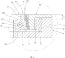
上述の技術や効果以外にも、回転モータの構造(10)の構造により、外部の可動部材(被駆動部材)と直接結合することができ、既知技術のように追加した回転軸部材によって伝動を行う必要がなく、また同じ効果を達成するものとしては、軸受(40)に第3結合部(44)をさらに含めることによって達成することもできる。 In addition to the above techniques and effects, the structure of the rotary motor structure (10) allows it to be directly coupled with an external movable member (driven member), and transmission is achieved by an additional rotating shaft member as in known technology. It need not be done and the same effect can be achieved by further including a third joint (44) in the bearing (40).
第3結合部(44)は複数の結合孔(441)を有し、それぞれは外環(41)の第2端(414)から軸方向沿いに内に向かって適当な深さで延在しており、これにより外環(41)の第2端(414)を、外部部材を担持する結合面として定義することができ、且つそれらの結合孔(441)によって外部部材と軸受(40)間の結合部位が提供される。もちろん、組み立ての便宜上、ボルトを螺合する方法によって組み立てを素早く完成させるため、結合孔(441)をねじ穴にすることができる。 The third connecting portion (44) has a plurality of connecting holes (441), each extending axially inward from the second end (414) of the outer ring (41) to a suitable depth. , whereby the second end (414) of the outer ring (41) can be defined as the coupling surface carrying the outer member, and the coupling holes (441) thereof provide the coupling between the outer member and the bearing (40). is provided. Of course, for the convenience of assembly, the coupling hole (441) can be a threaded hole to quickly complete the assembly by screwing the bolt.
上述の説明を通して、本考案が提供する回転モータの構造(10)はモータ自体の体積を縮小でき、精度を向上し得るだけでなく、軸受(40)によってモータ自体の回転時に必要な回転支持や外部部材の回転時の回転支持も提供可能であり、これにより、単一の軸受部材で第2部材と外部の回転部材に摩擦を減らす具体的な効果を提供することができる。つまり、本考案が主な目的において開示する簡素化された部材とは、モータ自体のみならず、モータと直接結合される被駆動部材間の伝動部分にまで拡げて言えることであり、その効果は明らかである。 Through the above description, the structure (10) of the rotary motor provided by the present invention can not only reduce the volume of the motor itself, improve the accuracy, Rotational support can also be provided during rotation of the outer member, whereby a single bearing member can provide the tangible effect of reducing friction between the second member and the outer rotating member. In other words, the simplified member disclosed in the main purpose of the present invention can be applied not only to the motor itself, but also to the transmission part between the driven members directly coupled with the motor, and the effect thereof is it is obvious.
上述で開示した具体的な実施形態に加えて、以下の点についても理解されたい。 In addition to the specific embodiments disclosed above, the following should also be appreciated.
軸受のタイプに関しては、開示した転がり軸受以外にも、例えば空気軸受や流体軸受、磁気軸受といった他の形態の軸受でもよく、いずれも本考案の保護範囲に属する。 Regarding the type of bearing, besides the disclosed rolling bearing, other forms of bearing such as air bearing, hydrodynamic bearing, magnetic bearing, etc., are all within the scope of protection of the present invention.
また、上述で開示した実施例中、第2結合部と軸受間の固定が第2結合部のノッチと凸体間の嵌合接続で結合されて成るものであるという技術内容は、その結合手段を限定するものではなく、その他の固定技術・手段によって凸凹の相補的構造の相対位置を入れ替えるなども可能であり、いずれも本考案の保護範囲である。 In addition, in the embodiment disclosed above, the technical content that the fixation between the second coupling portion and the bearing is coupled by fitting connection between the notch of the second coupling portion and the convex body is the coupling means. However, other fixing techniques and means can be used to replace the relative positions of the concave and convex complementary structures, all of which are within the protection scope of the present invention.
また、上述で開示した実施例は、ねじ穴で固定する第3結合部について具体的に例示しているが、これについても限定されず、例えば接着、ピンホール、はんだ付け、クランプ、嵌合接続又は他の固定技術・手段によって第3結合部と外部部材間の結合を達成させるなど、その他の結合手段でもよく、それらの技術内容も本考案の保護範囲である。 Further, although the embodiments disclosed above specifically exemplify the third joint portion fixed with a screw hole, the third joint portion is not limited to this. Or other connection means, such as other fixing techniques and means to achieve the connection between the third connection part and the external member, are also included in the scope of protection of the present invention.
10 回転モータの改良構造
20 第1部材
21 第1本体部
22 第1担持面
23 第1結合部
24 コイル
30 第2部材
31 第2本体部
32 第2担持面
33 磁石
34 第2結合部
40 軸受
41 外環
411 環状体
412 凸体
413 第1端
414 第2端
42 内環
421 第1端
422 第2端
43 転動部材
44 第3結合部
441 結合孔
C1 間隔
C2 距離
Claims (9)
環状を呈し、且つ前記第1本体部と同軸である第2本体部(31)と、前記第1担持面と相対し且つ互いに離されており、前記第2本体部の片側の円環面によって定義される第2担持面(32)と、前記第2本体部に位置する第2結合部(34)と、を有する第2部材(30)と、
前記第2本体部(31)の内側で同軸に位置しており、外環(41)と内環(42)を有し、前記外環(41)によって前記第2結合部(34)と接続固定され、且つ前記外環(41)の軸方向の一端部上に位置する第1端(413)は前記第1結合部(23)と離されており、前記内環(42)の軸方向の一端部上に位置する第1端(421)が前記第1結合部(23)と接続固定され、且つ前記内環(42)の軸方向の他端部上に位置する第2端(422)と、前記外環(41)の軸方向の他端部上に位置する第2端(414)とは、互いに半径方向の異なる平面上に位置する、軸受(40)と、を含む回転モータの構造(10)。 A first body portion (21) having an annular shape, a first bearing surface (22) defined by a toric surface on one side of said first body portion, and extending radially inwardly from said first body portion. a first member (20) having a residing first joint (23);
A second body portion (31) having an annular shape and being coaxial with said first body portion, facing and spaced apart from said first bearing surface, by means of an annular surface on one side of said second body portion. a second member (30) having a defined second bearing surface (32) and a second coupling portion (34) located on said second body portion;
coaxially positioned inside said second body portion (31), having an outer ring (41) and an inner ring (42), said outer ring (41) connecting with said second coupling portion (34); A first end (413) which is fixed and located on one axial end of the outer ring (41) is separated from the first connecting portion (23) and is axially connected to the inner ring (42). A first end (421) positioned on one end is connected and fixed to the first coupling part (23), and a second end (422) positioned on the other axial end of the inner ring (42) ) and a second end (414) positioned on the other axial end of the outer ring (41) are positioned on planes radially different from each other. structure (10).
前記外環(41)は、環状体(411)と、前記環状体に半径方向に突設された凸体(412)と、を含み、前記凸体と前記ノッチにより相補的に嵌合接続される、請求項1に記載の回転モータの構造。 the second coupling portion (34) is a notch recessed on the outer annular surface of the second body portion (31);
The outer ring (41) includes an annular body (411) and a convex body (412) projecting radially from the annular body, and the convex body and the notch are complementarily fitted and connected. 2. The rotary motor structure according to claim 1, wherein:
Priority Applications (1)
| Application Number | Priority Date | Filing Date | Title |
|---|---|---|---|
| JP2022002899U JP3239642U (en) | 2022-09-01 | 2022-09-01 | Structure of rotary motor |
Applications Claiming Priority (1)
| Application Number | Priority Date | Filing Date | Title |
|---|---|---|---|
| JP2022002899U JP3239642U (en) | 2022-09-01 | 2022-09-01 | Structure of rotary motor |
Publications (1)
| Publication Number | Publication Date |
|---|---|
| JP3239642U true JP3239642U (en) | 2022-10-27 |
Family
ID=83720707
Family Applications (1)
| Application Number | Title | Priority Date | Filing Date |
|---|---|---|---|
| JP2022002899U Active JP3239642U (en) | 2022-09-01 | 2022-09-01 | Structure of rotary motor |
Country Status (1)
| Country | Link |
|---|---|
| JP (1) | JP3239642U (en) |
-
2022
- 2022-09-01 JP JP2022002899U patent/JP3239642U/en active Active
Similar Documents
| Publication | Publication Date | Title |
|---|---|---|
| JP5840151B2 (en) | Rotating electric machine | |
| US7986068B2 (en) | Motor | |
| EP3480924B1 (en) | Speed reducing device having power source | |
| JP2008524975A (en) | Electric motor for rotation and axial movement | |
| EP3144497A1 (en) | Electric supercharger | |
| CN108092465B (en) | Mounting structure of rotary transformer of motor | |
| EP1717930A2 (en) | Electric actuator and a motor used therein | |
| JP3239642U (en) | Structure of rotary motor | |
| CN112491246B (en) | Magnetic adjusting ring component, magnetic gear, corresponding assembling method and composite motor | |
| CN218569951U (en) | Rotor, rotating electric machine, and pump | |
| US9853520B2 (en) | Molded motor and air-conditioning outdoor unit | |
| CN106374672A (en) | Motor rotor assembly and motor with assembly | |
| CN110492634B (en) | rotor | |
| CN117239958A (en) | Shafting components, axial flux motors and drones | |
| CN218829386U (en) | Construction of the rotary motor | |
| CN114142633B (en) | Stator, motor, compressor and refrigeration plant | |
| JP7204027B1 (en) | Rotating electric machine and its rotor | |
| CN113472169B (en) | Motor with a motor housing | |
| CN118713336B (en) | Motor, chassis system and vehicle | |
| CN111293822A (en) | motor | |
| US20260036128A1 (en) | Compressor and method for assembling compressor | |
| CN113472168B (en) | Motor | |
| CN220457198U (en) | Motor rotor supporting structure, motor and electric drive assembly | |
| JP2005341653A (en) | Electric motor | |
| TWM637397U (en) | Rotary motor structure |
Legal Events
| Date | Code | Title | Description |
|---|---|---|---|
| R150 | Certificate of patent or registration of utility model |
Ref document number: 3239642 Country of ref document: JP Free format text: JAPANESE INTERMEDIATE CODE: R150 |
|
| A623 | Registrability report |
Free format text: JAPANESE INTERMEDIATE CODE: A623 Effective date: 20221216 |
|
| R250 | Receipt of annual fees |
Free format text: JAPANESE INTERMEDIATE CODE: R250 |