JP2005180505A - Positioning device - Google Patents
Positioning device Download PDFInfo
- Publication number
- JP2005180505A JP2005180505A JP2003419388A JP2003419388A JP2005180505A JP 2005180505 A JP2005180505 A JP 2005180505A JP 2003419388 A JP2003419388 A JP 2003419388A JP 2003419388 A JP2003419388 A JP 2003419388A JP 2005180505 A JP2005180505 A JP 2005180505A
- Authority
- JP
- Japan
- Prior art keywords
- cotter
- parts
- fixing member
- screw shaft
- shaft
- Prior art date
- Legal status (The legal status is an assumption and is not a legal conclusion. Google has not performed a legal analysis and makes no representation as to the accuracy of the status listed.)
- Pending
Links
Images


Abstract
Description
本発明は、軸に軸受等を取り付ける際に、その軸線方向位置を位置決めできる位置決め装置に関する。 The present invention relates to a positioning device capable of positioning a position in an axial direction when a bearing or the like is attached to a shaft.
ボールねじのねじ軸やモータの回転軸を回転自在に支持するために、転がり軸受が用いられている。ここで、ねじ軸や回転軸には、ラジアル方向の力と共にアキシャル方向の力も作用するので、軸と転がり軸受とが軸線方向に相対移動しないように、転がり軸受を軸に対して固定する必要がある。転がり軸受を軸に固定するものとしては、特許文献1に示すようなサークリップが知られている。
A rolling bearing is used to rotatably support a screw shaft of a ball screw or a rotating shaft of a motor. Here, since the axial force as well as the radial force acts on the screw shaft and the rotating shaft, it is necessary to fix the rolling bearing to the shaft so that the shaft and the rolling bearing do not move relative to each other in the axial direction. is there. A circlip as shown in
ところが、サークリップは、弾性変形を利用して軸上の周溝に係合させるものであるため、より剛性が高いサークリップであれば、大きなアキシャル力を受けることができるものの、これを変形させるために強大な力が必要となり、従って取り付けが困難となる。一方、取り付け性を向上させるため、剛性の低いサークリップを用いると、大きなアキシャル力を受けることができなくなるという問題がある。 However, since the circlip engages with the circumferential groove on the shaft using elastic deformation, a circlip with higher rigidity can receive a large axial force, but it deforms it. For this reason, a great force is required, so that the mounting becomes difficult. On the other hand, when a circlip having low rigidity is used in order to improve attachment properties, there is a problem that it is impossible to receive a large axial force.
これに対し、軸上の位置決め部材としてコッタが知られている。コッタは、特許文献2に示すように、内燃機関のバルブとをリテーナに組み付ける際に用いられるものであり、周方向に分割された複数の部材を、軸上の周溝に係合させ、リテーナで互いの分解を防ぐことにより、バルブに生じる強いアキシャル力を受けることができるようになっている。
しかるに、特許文献2に示すごときコッタは、リテーナがバルブスプリングによって一方向に付勢されているために、それらの分解が阻止されるようになっており、仮にバルブスプリングからの付勢力がなくなったとすると、コッタは分解して周溝から脱落する恐れがある。コッタが分解してしまうと、もはや位置決め機能を発揮することができない。
However, in the cotter shown in
本発明は、かかる問題点に鑑みてなされたものであり、軸上で軸受などを適切に位置決めできる位置決め装置を提供することを目的とする。 The present invention has been made in view of such problems, and an object of the present invention is to provide a positioning device capable of appropriately positioning a bearing or the like on a shaft.
本発明の位置決め装置は、
周溝を有する軸に対して取り付けられる位置決め装置であって、
前記周溝に係合する複数の部品からなるコッタと、
前記コッタの部品の周囲を囲うことでその分解を阻止する固定部材とを有し、
前記固定部材は前記軸の外周面に当接する当接部を有することを特徴とする。
The positioning device of the present invention comprises:
A positioning device attached to a shaft having a circumferential groove,
A cotter comprising a plurality of parts engaging with the circumferential groove;
A fixing member that prevents disassembly by surrounding the parts of the cotter,
The fixing member has a contact portion that contacts the outer peripheral surface of the shaft.
本発明の位置決め装置は、周溝を有する軸に対して取り付けられる位置決め装置であって、前記周溝に係合する複数の部品からなるコッタと、前記コッタの部品の周囲を囲うことでその分解を阻止する固定部材とを有し、前記固定部材は前記軸の外周面に当接する当接部を有するので、前記当接部の摩擦力により前記固定部材の軸線方向移動が阻止されるため、バルブスプリングなどの付勢部材がない場合でも、前記コッタの分解が阻止され、それにより強大なアキシャル力を受けることができる。 The positioning device of the present invention is a positioning device that is attached to a shaft having a circumferential groove, and is disassembled by surrounding a cotter composed of a plurality of parts engaging with the circumferential groove and the parts of the cotter. Since the fixing member has a contact portion that contacts the outer peripheral surface of the shaft, the axial movement of the fixing member is blocked by the frictional force of the contact portion. Even when there is no urging member such as a valve spring, the cotter can be prevented from being disassembled, thereby receiving a strong axial force.
更に、前記固定部材は、板材をプレス成形することで形成されると、低コスト且つ安価に製造できる。 Furthermore, when the fixing member is formed by press-molding a plate material, it can be manufactured at a low cost and at a low cost.
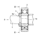
以下、本発明の実施の形態を図面を参照して以下に詳細に説明する。図1は、本実施の形態の位置決め装置を用いて、ねじ軸に玉軸受を固定した状態を示す断面図である。図2は、図1の構成を矢印II方向に見た図であり、図3は、図1の構成をIII-III線で切断して矢印方向に見た図であり、図4は、固定部材の断面図である。 Hereinafter, embodiments of the present invention will be described in detail with reference to the drawings. FIG. 1 is a cross-sectional view showing a state in which a ball bearing is fixed to a screw shaft using the positioning device of the present embodiment. 2 is a view of the configuration of FIG. 1 viewed in the direction of arrow II, FIG. 3 is a view of the configuration of FIG. 1 cut along the line III-III, and viewed in the direction of the arrow, and FIG. It is sectional drawing of a member.
図1において、ボールねじ機構などに用いられるねじ軸1の周囲には、玉軸受2が嵌合している。玉軸受2は、不図示のハウジングに対して、ねじ軸1を回転自在に支持している。
In FIG. 1, a ball bearing 2 is fitted around a
ねじ軸1には周溝1aが形成されている。周溝1a内には、コッタ3を構成する2つの部品3a、3bが係合配置されている。部品3a、3bは同じ半リング形状を有している。
A
周溝1aに嵌合した部品3a、3bの周囲を囲うようにして、固定部材4が配置されている。固定部材4は、短円筒状の本体4aと、本体4aの一端から半径方向に内在するフランジ部4bと、フランジ部4bの内径側縁から半径方向内方及び軸線方向外方に延在する当接部4cを有している。本体4aの内径は、組み付けた状態での部品3a、3bの外径よりわずかに大きい。
The
固定部材4は、板材をプレス成形して形成され、当接部4cは、フランジ部4bの内径側から周方向に等間隔で6カ所切り込みを形成し、切り込んだ部分を軽く折り曲げることで形成されてなる。当接部4cの先端で形成する円の径は、ねじ軸1の当接部位の径よりわずかに小さくなっている。コッタ3と固定部材4とで位置決め装置を構成する。
The
本実施の形態の位置決め装置によれば、ブロック状のコッタ3が、周溝1aに深く係合しているため、部品3a、3bがバレない(溝から脱落して分解しない)限り、玉軸受2とねじ軸1との間に強大なアキシャル力が作用した場合でも、これを確実に受け止めることができる。一方、固定部材4は、本体4aでコッタ3の部品3a、3bを囲うことで、それらのバレ(分解)を阻止することができるため、玉軸受2とねじ軸1との間に作用するアキシャル力を安定して受けることができる。
According to the positioning device of the present embodiment, since the block-
当接部4cは、ねじ軸1の外周面に当接することで摩擦力を発生し、固定部材4が軸線方向に移動してコッタ3の部品3a、3bのバレを招くことを防止する。固定部材4には、玉軸受2とねじ軸1との間に作用するアキシャル力は伝達されないので、当接部4cの発生する摩擦力は低くて足りる。固定部材4の相対移動を防止するために、サークリップを別個に設けることも考えられるが、サークリップの他に取り付け用溝も新たに必要となり、従って本実施の形態の方がコスト及び取り扱いに有利である。
The
図5は、ねじ軸に対して位置決め装置を組み付ける際の手順を示す図である。図5に示すように、ねじ軸1の周溝1aに対して、コッタ3の部品3a、3bをそれぞれ半径方向外方から係合させ、更に固定部材4をねじ軸1の端部から挿入し本体4aで部品3a、3bを包囲することで、位置決め装置の組付けが完了する。
FIG. 5 is a diagram illustrating a procedure when the positioning device is assembled to the screw shaft. As shown in FIG. 5, the
以上、本発明を実施例を参照して説明してきたが、本発明は上記実施の形態に限定して解釈されるべきではなく、適宜変更・改良が可能であることはもちろんである。例えば、本発明は軸受に限らず、歯車などを軸に固定する際に用いることができる。 The present invention has been described with reference to the embodiments. However, the present invention should not be construed as being limited to the above-described embodiments, and can be modified or improved as appropriate. For example, the present invention is not limited to a bearing, and can be used when a gear or the like is fixed to a shaft.
1 ねじ軸
2 玉軸受
3 コッタ
4 固定部材
1
Claims (2)
前記周溝に係合する複数の部品からなるコッタと、
前記コッタの部品の周囲を囲うことでその分解を阻止する固定部材とを有し、
前記固定部材は前記軸の外周面に当接する当接部を有することを特徴とする位置決め装置。 A positioning device attached to a shaft having a circumferential groove,
A cotter comprising a plurality of parts engaging with the circumferential groove;
A fixing member that prevents disassembly by surrounding the parts of the cotter,
The positioning device, wherein the fixing member has an abutting portion that abuts on an outer peripheral surface of the shaft.
The positioning device according to claim 1, wherein the fixing member is formed by press-molding a plate material.
Priority Applications (1)
| Application Number | Priority Date | Filing Date | Title |
|---|---|---|---|
| JP2003419388A JP2005180505A (en) | 2003-12-17 | 2003-12-17 | Positioning device |
Applications Claiming Priority (1)
| Application Number | Priority Date | Filing Date | Title |
|---|---|---|---|
| JP2003419388A JP2005180505A (en) | 2003-12-17 | 2003-12-17 | Positioning device |
Publications (2)
| Publication Number | Publication Date |
|---|---|
| JP2005180505A true JP2005180505A (en) | 2005-07-07 |
| JP2005180505A5 JP2005180505A5 (en) | 2006-11-09 |
Family
ID=34781301
Family Applications (1)
| Application Number | Title | Priority Date | Filing Date |
|---|---|---|---|
| JP2003419388A Pending JP2005180505A (en) | 2003-12-17 | 2003-12-17 | Positioning device |
Country Status (1)
| Country | Link |
|---|---|
| JP (1) | JP2005180505A (en) |
Cited By (2)
| Publication number | Priority date | Publication date | Assignee | Title |
|---|---|---|---|---|
| JP2009095221A (en) * | 2007-05-17 | 2009-04-30 | Nsk Ltd | Actuator |
| JP2010203475A (en) * | 2009-02-27 | 2010-09-16 | Honda Motor Co Ltd | Output sprocket installing structure |
-
2003
- 2003-12-17 JP JP2003419388A patent/JP2005180505A/en active Pending
Cited By (3)
| Publication number | Priority date | Publication date | Assignee | Title |
|---|---|---|---|---|
| JP2009095221A (en) * | 2007-05-17 | 2009-04-30 | Nsk Ltd | Actuator |
| JP2013061070A (en) * | 2007-05-17 | 2013-04-04 | Nsk Ltd | Actuator |
| JP2010203475A (en) * | 2009-02-27 | 2010-09-16 | Honda Motor Co Ltd | Output sprocket installing structure |
Similar Documents
| Publication | Publication Date | Title |
|---|---|---|
| KR101646904B1 (en) | Strain wave gearing | |
| JP2009264526A (en) | Bearing arrangement of supercharger | |
| JP4219374B2 (en) | mechanical seal | |
| JP2007032671A (en) | Needle roller bearing, and bearing structure | |
| US20110203398A1 (en) | Divided Toothed Wheel | |
| KR100592684B1 (en) | Reducer | |
| JP2005121230A (en) | System for fixing rolling bearing in axial direction | |
| JP2005188527A (en) | Rolling bearing and motor device using the same | |
| JP2005042894A (en) | Double row rolling bearing device | |
| JP2005180505A (en) | Positioning device | |
| JP2008232179A (en) | Bearing device | |
| JP2006064082A (en) | Rolling bearing unit | |
| JP4277558B2 (en) | Mounting structure for rolling bearing shafts, stoppers | |
| JP5026301B2 (en) | Rolling bearing unit and manufacturing method thereof | |
| JP2014126048A (en) | Gear and electric motor using gear | |
| JP2006311657A (en) | Electric actuator | |
| JP2005337383A (en) | Bearing device for pulley | |
| WO2019111903A1 (en) | Tripod constant velocity universal joint | |
| JP2006194307A (en) | Clutch release bearing and seal member pushing fixture | |
| CN111271382B (en) | Rolling bearing fixing structure | |
| JP5012419B2 (en) | Thrust needle roller bearing fixing method | |
| JP4919161B2 (en) | Wheel support device | |
| JP2009079630A (en) | Wheel support device | |
| JP2010190361A (en) | Ball screw device | |
| JP2007127175A (en) | Resin pulley |
Legal Events
| Date | Code | Title | Description |
|---|---|---|---|
| A521 | Written amendment |
Effective date: 20060925 Free format text: JAPANESE INTERMEDIATE CODE: A523 |
|
| A621 | Written request for application examination |
Effective date: 20060925 Free format text: JAPANESE INTERMEDIATE CODE: A621 |
|
| A977 | Report on retrieval |
Effective date: 20081003 Free format text: JAPANESE INTERMEDIATE CODE: A971007 |
|
| A131 | Notification of reasons for refusal |
Free format text: JAPANESE INTERMEDIATE CODE: A131 Effective date: 20081007 |
|
| A521 | Written amendment |
Effective date: 20081128 Free format text: JAPANESE INTERMEDIATE CODE: A523 |
|
| A02 | Decision of refusal |
Effective date: 20081218 Free format text: JAPANESE INTERMEDIATE CODE: A02 |