EP2351865A1 - Alliage amélioré résistant à l'usure - Google Patents
Alliage amélioré résistant à l'usure Download PDFInfo
- Publication number
- EP2351865A1 EP2351865A1 EP11003390A EP11003390A EP2351865A1 EP 2351865 A1 EP2351865 A1 EP 2351865A1 EP 11003390 A EP11003390 A EP 11003390A EP 11003390 A EP11003390 A EP 11003390A EP 2351865 A1 EP2351865 A1 EP 2351865A1
- Authority
- EP
- European Patent Office
- Prior art keywords
- austenite
- high chromium
- cast iron
- chromium white
- white cast
- Prior art date
- Legal status (The legal status is an assumption and is not a legal conclusion. Google has not performed a legal analysis and makes no representation as to the accuracy of the status listed.)
- Withdrawn
Links
Images


Classifications
-
- C—CHEMISTRY; METALLURGY
- C22—METALLURGY; FERROUS OR NON-FERROUS ALLOYS; TREATMENT OF ALLOYS OR NON-FERROUS METALS
- C22C—ALLOYS
- C22C37/00—Cast-iron alloys
- C22C37/06—Cast-iron alloys containing chromium
- C22C37/08—Cast-iron alloys containing chromium with nickel
-
- C—CHEMISTRY; METALLURGY
- C22—METALLURGY; FERROUS OR NON-FERROUS ALLOYS; TREATMENT OF ALLOYS OR NON-FERROUS METALS
- C22C—ALLOYS
- C22C37/00—Cast-iron alloys
- C22C37/10—Cast-iron alloys containing aluminium or silicon
Definitions
- the present invention relates to wear resistant, high chromium white irons which are suitable for hardfacing of components and also for direct casting of complete products, and which enable improved fracture toughness.
- Chromium white irons in particular high chromium white irons, resist wear as a result of their content of very hard M 7 C 3 carbides, where M is Fe,Cr or Cr,Fe but may include small amounts of other elements such as Mn or Ni, depending upon the composition.
- the wear resistant high chromium white irons may be hypoeutectic, eutectic or hypereutectic.
- the hypoeutectic chromium white irons have up to about 3.0% carbon, and their microstructure contains primary dendrites of austenite in a matrix of a eutectic mixture of M 7 C 3 carbides and austenite.
- the eutectic white irons have from about 3.0% to about 4.0% carbon and a microstructure of a eutectic mixture of M 7 C 3 carbides and austenite.
- the hypereutectic chromium white irons have from about 3.5% to about 5.0% carbon, while their microstructure contains primary M 7 C 3 carbides in a matrix of a eutectic mixture of M 7 C 3 carbides and austenite.
- the M 7 C 3 carbides either as eutectic carbides or primary carbides, that provides the alloy with its wear characteristics.
- the hypereutectic white irons are considered to have higher volume fractions of the hard and wear resistant M 7 C 3 carbides than the hypoeutectic white irons, and are thus often the preferred alloy for many hardfacing applications.
- the hypereutectic white irons generally are not favoured for casting, due to stress induced cracking during cooling.
- AU-A-28865/84 in fact predominantly solves the cracking problem of cast compositions by forming them as cast composites - namely by creating a composite component comprising the preferred alloy metallurgically bonded to a substrate, thus assisting with avoiding the likelihood of cracking upon the cast alloy cooling.
- AU-A-28865/84 seeks to overcome the disadvantages of low fracture toughness and cracking with hypereutectic castings having greater than 4.0 wt.% carbon by ensuring the formation in a composite casting of primary M 7 C 3 carbides with mean cross-sectional dimensions no greater than 75 micron, and suggests a variety of mechanisms for doing so.
- AU-A-28865/84 aims to overcome the problem by forming composite components and limiting the size of the primary M 7 C 3 carbides in the alloy itself.
- United States patent 5,803,152 also seeks to refine the microstructure of, in particular, thick section hypereutectic white iron castings, in order to maximise nucleation of primary carbides, thereby enabling an increase not only in fracture toughness but also in wear resistance.
- This refinement is achieved by introducing a particulate material into a stream of molten metal as the metal is being poured for a casting operation.
- the particulate material is to extract heat from, and to undercool, the molten metal into the primary phase solidification range between the liquidus and solidus temperatures.
- United States patent 6,375,895 points out that most prior art high chromium white irons for hardfacing always show a more or less dense network of cracks (or check cracking) in the as-welded condition, despite precautions to avoid this. US 6,375,895 indicates that the comparative hardness of primary carbides (about 1700 Brinell hardness number (BHN)) in a soft austenite matrix (about 300 BHN to 600 BHN) gives rise to shrinkage cracks on cooling from the molten state.
- BHN Brinell hardness number
- the white iron of the invention does not require the formation of composite components, or the use of complex casting techniques. Also, the use of costly pre-heating techniques are not necessary for use of the white iron for hardfacing.
- the present inventor has been the first to recognise the causes of the fracture toughness problem with wear-resistant, high chromium white irons.
- the inventor has recognised the presence of a thin layer of martensite at interfaces between the M 7 C 3 carbides and the austenite, and has also recognised that this thin layer of martensite enables or at least initiates cracking. This applies whether the M 7 C 3 carbides are primary carbides and the austenite is that of eutectic matrix, or the M 7 C 3 carbides are eutectic carbides and the austenite is of the eutectic or, where relevant, the austenite is primary austenite.
- the findings apply to hypoeutectic, eutectic and hypereutectic high chromium white irons for use in producing castings.
- the findings also apply to eutectic and hypereutectic alloys used for weld deposition and for many, if not all, hypoeutectic alloys used for weld deposition.
- this thin layer of martensite is normally less than 1 micron thick, but may be up to several microns thick, or may be as thin as several nanometres.
- the layer may not be entirely continuous about a carbide and may not be uniform in thickness. Such a layer will of course only normally be visible using electron microscopes or the like.
- weld deposits formed during hardfacing are subjected to residual tensile stresses due to shrinkage during cooling after the weld solidifies.
- the thin, hard and brittle layer of martensite adjacent the M 7 C 3 carbides relieves these tensile stresses by cracking.
- the softer austenite is able to deform to accommodate the residual tensile stresses, obviating the initiation of cracking and minimising crack propagation where some microcracking still occurs.
- the inventor additionally has found that martensite at the interfaces between M 7 C 3 carbides and austenite is not the sole cause of cracking of castings and weld deposited hardfacing.
- Some alloy additions are found to increase interconnectivity of the M 7 C 3 carbide where the level of at least one of the additions is such that undercooling of the melt occurs before solidification. This applies to both castings and to weld deposits and where this is in conjunction with the presence of martensite at M 7 C 3 carbide and austenite interfaces, crack initiation and propagation essentially is unable to be avoided.
- M 7 C 3 carbide interconnectivity occurs in alloys which are not prone to the presence of martensite at those interfaces, that source of crack initiation is avoided, although crack initiation and propagation still is largely unavoidable.
- the inventor has found that, in large part, the solution to both sources of crack initiation and propagation in high chromium white irons, whether used in castings or weld deposition, is the same.
- the present invention provides a wear resistant, high chromium white iron, wherein said white iron in an unheat-treated condition has a microstructure substantially comprising austenite and M 7 C 3 carbides and wherein said white iron contains at least one martensite promoter and at least one austenite stabiliser, with said martensite promoter and austenite stabiliser being present at respective levels to achieve a balance between their effects whereby the white iron in an unheat-treated condition has a microstructure characterised by at least one of:
- the white iron is in an as-cast condition and said respective levels achieve a balance whereby the white iron is substantially free of martensite at interfaces between the austenite and M 7 C 3 carbides.
- the white iron comprises hardfacing provided over a substrate by weld deposition, and the hardfacing is substantially free of check cracking.
- the balance between the effects of the martensite promoter and the austenite stabiliser may be such that M 7 C 3 carbides of said microstructure exhibit a relatively low level of interconnectivity between carbide particles.
- the low level of interconnectivity preferably is such that the microstructure is substantially free of branched carbide particles and, where relevant, said respective levels also achieve a balance whereby the white iron is substantially free of martensite at interfaces between the austenite and M 7 C 3 carbides.
- the present invention provides wear-resistant, high chromium white iron alloys having substantially no martensite at interfaces between the M 7 C 3 carbides and austenite such that the alloys, either as-cast or as deposited for hardfacing, are substantially crack free.
- reference to there being substantially no martensite at those interfaces does not preclude the presence of some martensite within austenitic regions away from the interfaces.
- the invention is characterised by the prevention of the formation of the thin layer of martensite at interfaces between the M 7 C 3 carbides and austenite, and does not necessitate the total exclusion of all martensite, although this may occur. Indeed, in some compositions the presence of martensite other than at those interfaces is desirable.
- the present invention provides a wear-resistant, high chromium white iron having a sufficient balance of at least one martensite promoter and at least one austenite stabiliser such that there is substantially no martensite at interfaces between the M 7 C 3 carbides and austenite such that the white iron, either as-cast or as-deposited for hardfacing, is substantially crack free.
- Silicon as a martensite promoter, is a member of the group of alloying elements that act to promote the formation of martensite. Alloying elements of that group also include boron.
- silicon is the martensite promoter of principal importance for the purpose of achieving the required balance with the at least one austenite stabiliser.
- boron can be used as a martensite promoter, such as up to about 1% or even as high as 2%. The boron can influence the action of silicon, or it can be used as the sole martensite promoter. In general, the control required by the invention is described herein with reference to silicon as the martensite promoter and to the at least one austenite stabiliser, although it is to be borne in mind that boron can be used as martensite promoter.
- the at least one austenite stabiliser is a member of the group of alloying elements that act to promote and stabilise the formation of austenite. Alloying elements of that group include manganese, nickel, copper and molybdenum. These elements can be used alone or in combination. Of these four elements, manganese and nickel are found to be particularly beneficial for the purpose of the present invention. The control required by the invention therefore is described with reference to manganese and/or nickel as the austenite stabiliser, although minor amounts of at least one of the other austenite stabilisers can be present in addition. Also, it is to be borne in mind that the other stabilisers can be used instead of manganese and/or nickel.
- the thin layer of martensite at interfaces between M 7 C 3 carbides and austenite is avoided by a ⁇ sufficient balance' of various alloying elements, in the form of suitable amounts of austenite stabilisers (such as manganese and/or nickel) and martensite promoters (such as silicon and/or boron).
- austenite stabilisers such as manganese and/or nickel
- martensite promoters such as silicon and/or boron
- martensite promoters such as silicon have been suggested for addition to some chromium white irons to increase the fluidity of the melt during hardfacing or casting.
- a martensite promoter such as silicon can produce a previously unsuspected cumulatively deleterious result. It has been found that the presence of the martensite promoter can have the opposite effect to the preferred austenite stabilisers (manganese and nickel) upon the formation of martensite.
- austenite stabilisers manganese and nickel
- the resolution is such that, the eutectic is perceived as comprising M 7 C 3 carbides and austenite, without martensite.
- those resolutions may show primary dendrites as comprising austenite alone or as comprising austenite within which there may be regions of martensite, as anticipated. In the latter case, the martensitic regions would be considered to be acceptable, given that they are contained within austenite.
- the photomicrographs show what is expected and there is no reason to look further as cracking appears to be satisfactorily explained by residual stress.
- silicon is able to have an active, if previously unsuspected, role in promoting the formation of martensite despite austenite stabilisation. That role is deleterious in that the martensite formed is at the interfaces between M 7 C 3 carbides and austenite.
- This can be carbides and austenite of the eutectic phase, or primary austenite and eutectic carbide or primary carbide and eutectic austenite, or relevant combinations of these situations.
- Silicon can increase the undercooling in the melt before solidification occurs which increases interconnectivity of eutectic M 7 C 3 carbides and, for hypereutectic microstructures, increases the interconnectivity of primary M 7 C 3 carbides. Overall brittleness of a casting or weld deposit therefore increases. However, if silicon is present at a controlled level such that no substantial undercooling occurs, it has been found that the silicon can serve to decrease the interconnectivity of the primary M 7 C 3 carbides and of eutectic M 7 C 3 carbides. With such decrease in interconnectivity, fracture toughness, wear resistance and the resistance to thermal shock are increased. Higher levels of silicon can be applied to reduce the interconnectivity of eutectic M 7 C 3 carbides in hypoeutectic compositions as the complex regular eutectic with high interconnectivity does not form in hypoeutectic alloys.
- the level of silicon in chromium white irons according to the invention is from 0.25 to 3.5%. However, more preferably the level is from 0.5 to 3.25%. In some forms (depending on microstructure), the silicon levels should not be higher than about 2.75%, as will be explained below. Boron is somewhat more potent than silicon and, as indicated above, boron need only be present at levels up to about 1%, or only up to about 2%.
- the percentages are by weight.
- the percentages allow for dilution by the base metal, such as from 10 to 40%.
- the austenite stabilisers manganese and nickel are both present in the alloy in an amount of from 4.0% to about 12%, such as from 4.0% to 8.0% in order to assist in preventing the transformation of austenite to the martensite.
- manganese and/or nickel can be present at up to about 12% in at least some instances the preferred range is from 4.0% to 8.0%.
- austenite stabilisers When the alternative austenite stabilisers are used, copper typically can be used at substantially the same levels as indicated for manganese and/or nickel. Molybdenum however needs to be used at higher levels to allow for a proportion which forms carbide and, hence, is not available as austenite stabiliser. Thus, it is appropriate to consider an equivalence of molybdenum which provides similar austenite stabilisation to the other alloy additions. However, it is preferred that the two alternatives, if used at all, be used in combination with manganese and/or nickel, and at a relatively low level. This is particularly so with molybdenum in view of its cost.
- the total level of austenite stabiliser is not in excess of about 20%, and more preferably is not in excess of about 16%.
- the balance required by the present invention necessitates control of a number of variables. These include the level of silicon, the level of manganese and the level of nickel. Manganese and nickel can be regarded as the one variable, given that in large part they are interchangeable. However, they do differ slightly in their effectiveness as austenite stabilisers, and it therefore is preferred to regard the levels of manganese and nickel as separate variables.
- a fourth variable is cooling rate. However, as a variable, cooling rate has greater relevance in casting, as the scope for its variation is somewhat limited in weld deposition.
- attainment of the balance can be determined by presenting a magnet to the trial casting or weld deposit. If ferromagnetism (indicative of the presence of martensite in the present context) is not evident, at least approximate attainment of the balance has been achieved. However, it is appropriate to proceed beyond this to a metallographic examination to confirm that there is no martensite at the interface between the M 7 C 3 carbides and the austenite.
- the amount of chromium present is preferably from 8% to 50%. More preferably the chromium level is from 10% to 30%.
- the carbon content will typically be from 1.0% to 6.0%. However, there are overlapping sub-ranges for the level of carbon, depending upon whether the white iron is of hypoeutectic, eutectic or hypereutectic composition.
- the carbides will thus be predominantly of the M 7 C 3 type, although small amounts of less hard M 23 C 6 carbides can be present, such as in primary austenite regions.
- the amount of carbon present usually will be from 1.0% to 3.0%.
- the amount of carbon present will usually be from 3.0% to 4.0%, while a hypereutectic composition usually will have from 3.5% to 5.0%.
- these ranges may alter, depending upon the presence of other alloying elements.
- the alloy includes an amount of up to about 10% (total) niobium and/or vanadium (which might be added to precipitate hard niobium and vanadium carbides to increase wear resistance), then the relevant amounts of carbon present in the respective compositions will shift as follows: Hypoeutectic 2.0% to 4.0% Eutectic 4.25% to 4.75% Hypereutectic 5.0% to 6.0%
- Figure 1 illustrates the liquidus surface projections for ternary Fe-Cr-C for high chromium white irons at the Fe-rich corner of metastable C-Cr-Fe liquidus surface.
- the ternary compositions have up to 6% carbon and up to 40% chromium. They also contain small percentages of manganese and silicon.
- the liquidus surface projections in Figure 1 can be used to show the relationship between microstructure and content of carbon and chromium.
- the region marked y indicates hypoeutectic compositions.
- the compositions at points A, B, C, D and E all fall within general ranges herein referred to as Group I.
- compositions A and B fall into the hypoeutectic region and are close to the boundaries.
- Eutectic microstructures fall on the line from U 1 to U 2 , from a composition close to B along the line to point C.
- Hypereutectic compositions are within the region marked M 7 C 3 , which includes compositions D and E.
- any cooling regime that tends to enhance or promote the transition of austenite to martensite preferably is avoided.
- higher silicon contents can enable faster cooling rates.
- Tables I and II Illustrative, non-limiting examples of chromium white iron compositions for use in castings or weld deposits in accordance with the present invention are set out in Tables I and II.
- Table I sets out the compositions of Group I, which cover the compositions at points A, B, C, D and E shown in Figure 1 .
- Table II covers similar compositions that for reasons detailed above, differ in that they include niobium and/or vanadium.
- a high chromium white iron casting, which had been subjected to industrial use was cut up to provide segments from which specimens for microstructural characterisation were obtained.
- the segments were cut using abrasive water-jet cutting.
- the specimens were cut from the segments with a thin carborundum rotating disc (wafer disc) cooled with copious amounts of a water based coolant.
- the specimens were examined using an Olympus reflected light microscope at magnifications up to and including X500.
- the specimens were examined in the unetched and etched conditions.
- the etchant was acid ferric chloride (5g FeCl 3 , 10ml HCl, 100ml H 2 O)
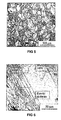
- Figure 2 is a photomicrograph of polished and acid ferric chloride etched section of a specimen taken from the industry casting.
- the field of Figure 2 is at the intersection of a subsurface crack and a surface breaking crack. These are large cracks and probably occurred during cooling down after solidification of the casting.
- FIG. 2 and 3 The microstructure of Figures 2 and 3 shows the industry casting to be in the as-cast condition.
- the chromium white iron of the industry casting from which Figures 2 and 3 were derived was a hypereutectic composition shown in Table III.
- Table III Industry Casting Composition % C Mn Si Ni Cr Mo Cu Fe/Impurities 4.5 1.90 0.49 0.12 34 0.95 0.07 Balance
- the microstructure exhibits only primary M 7 C 3 carbide and austenite at the respective magnifications shown.
- the microstructure thus is significantly different to that of the usual high chromium white iron despite similar white iron composition.
- the driving force for the growth of the carbide was sufficient for the carbide to solidify independently of the austenite and, hence, a divorced eutectic resulted.
- the microstructure shown in Figures 2 and 3 has primary M 7 C 3 carbides (white) in a divorced eutectic microstructure.
- a complex regular structure, with its interconnected carbide rods, has been avoided. This is beneficial since the preferred crack path in high chromium white iron weld deposits and castings is along the interface between the M 7 C 3 carbides and the austenite.
- the interconnected complex regular eutectic carbide structure provides long continuous paths along which cracks can propagate, making elimination of that structure desirable.
- cracking still has occurred. The reason for this is evident from Figure 4 .
- Figure 4 The higher magnification of Figure 4 was taken just above the intersection of the cracks shown in Figure 2 , just to the right of the vertical crack.
- the lighter coloured phase is the primary M 7 C 3 carbide, while the darker matrix predominantly is divorced eutectic austenite.
- the edge regions of the austenite, at interfaces between the austenite and M 7 C 3 carbide have a layer of martensite indicated by black arrows.
- the white arrow is pointing to a region of precipitated M 23 C 6 carbide within the austenite.
- the martensite forms a continuous layer at the M 7 C 3 carbide - austenite interfaces, as has been established by transmission electron microscopy (TEM).
- TEM transmission electron microscopy
- the black arrows only indicate regions where the martensite is resolvable at the magnification of Figure 4 .
- TEM shows that the martensite layer is actually composed of two very thin martensite layers. These include a thin, very brittle high carbon martensite layer adjacent to the M 7 C 3 carbide and a layer of less brittle, lower carbon martensite adjacent to the austenite.
- some martensite needles can be seen extending some distance from the interface into the austenite.
- the composition of most commercial high chromium white iron castings is limited to compositions up to eutectic composition.
- wear rate of high chromium white irons is directly related to the volume fraction of M 7 C 3 carbide, both primary and eutectic, and therefore hypoeutectic alloys and eutectic alloys have a higher wear rate than hypereutectic alloys in most circumstances.
- the choice of the hypoeutectic and eutectic compositions can minimise cracking by minimising the interfacial area between the M 7 C 3 carbide and the austenite, which we find is the preferred crack path due to the interfacial layer of martensite.
- the commercial alloy of Figures 2 to 4 has a hypereutectic composition and, as indicated, the sample supplied contained cracks and interfacial martensite.
- High chromium white irons according to the present invention can be hypoeutectic, eutectic or hypereutectic, and can be used in either the as-cast or heat-treated condition.
- Two compositions of hypereutectic have been trialled using small slowly cooled crucible castings.
- a micrograph of an acid ferric chloride etched sample from one of the small slowly cooled crucible castings is shown in Figure 5 , while the trialled compositions are set out in Table IV.
- Table IV Hypereutectic Casting Compositions According to the Invention C Mn Si Cr Ni Fe/Impurities Alloy 1: 4.25 9.31 2.18 27.45 4.07 Balance Alloy 2: 4.73 11.16 1.39 28.56 8.46 balance
- the light etched phase is the hexagonal primary M 7 C 3 carbide rods and these are surrounded by an austenite halo.
- Figure 5 which is similar to that of Figure 2
- Figure 6 there does not appear to be a dark layer of interfacial martensite at the interface between either the primary or eutectic M 7 C 3 carbides and the austenite.
- Figure 6 enables closer scrutiny using optical microscopy (at a resolution better than Figure 4 ), but also failed to reveal any martensite at the interface.
- the large volume of primary carbides in the microstructure indicates that the alloy is of hypereutectic composition. As stated earlier, the wear resistance increases with increasing volume fraction of carbides, particularly primary carbides.
- the industry casting microstructure of Figures 2 to 4 contained fine primary M 7 C 3 carbide in a divorced austenitic matrix indicating it was of hypereutectic composition and in the as-cast condition.
- the industry casting microstructure had an interfacial layer of martensite between the M 7 C 3 carbide and the austenite. Due to the relatively slow cooling rate of the industry casting the martensite layer could be resolved in the optical microscope.
- the present invention enables the interfacial martensite to be avoided.
- the microstructure of the slowly cooled castings of the trial compositions according to the present invention showed that the castings were of hypereutectic composition, that the castings did not show any evidence of martensite at the interfacial regions and that there were no cracks evident.
- compositions in accordance with the invention were not subjected to TEM, a further simple test is able to show the presence or absence, respectively, of martensite in the microstructure of Figures 2 to 4 , and that of Figures 5 and 6 .
- the hypereutectic chromium white irons the only ferromagnetic phase potentially present in the as-cast condition is martensite.
- the industry casting from which the photomicrographs of Figures 2 to 4 were derived was ferromagnetic and able to strongly attract a magnet, clearly indicating the presence of martensite.
- the casting from which Figures 5 and 6 were derived and other castings based on the compositions of Table IV did not attract a magnet, clearly indicating the absence of martensite.
- the invention again enables the substantially complete prevention of formation of a martensite layer at the interfaces between M 7 C 3 carbides and austenite.
- This is achieved in essentially the same way as described for castings, by a suitable balance between silicon as a martensite promotor and the austenite stabilisers manganese and nickel.
- a further significant benefit can be achieved in weld deposition. This is the avoidance of check cracking as a consequence of the prevention of martensite formation and also a reduction in the level of interconnectivity of M 7 C 3 carbides. The latter result is illustrated in the following.
- Identical sample preparation techniques were used for each of the industry samples. The preparation of samples involved selecting sections and plasma cutting them to a size suitable for manipulation in an abrasive cutter. Samples for metallographic examination were sectioned using a carborundum abrasive disk and water based lubricant at a suitable distance from the plasma cut region to ensure no microstructural changes took place due to heating during cutting. Approximate 25 millimetres long by 10 millimetres wide sections were taken transversely and longitudinally to the direction of the weld beads. The viewing plane of the transverse samples is across consecutive weld beads and along a weld bead for the longitudinal sample. These sections were polished using five grades of silicon carbide paper and polished to a 1-micron finish using diamond paste. The polished samples were etched in acid ferric chloride (5g FeCl 3 , 10ml HCl, 100ml H 2 O for viewing under an optical light microscope.
- acid ferric chloride 5g FeCl 3 , 10ml HCl, 100
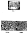
- FIG. 7 Representative industry samples of the hardfacing shown in Figure 7 were taken transversely and longitudinally to the weld beads and metallographically prepared.
- Figures 8a and 8b show the respective microstructures in which acid ferric chloride etching shows the hypereutectic composition of the high chromium white iron is indicated by the presence of primary M 7 C 3 carbides.
- the chemical composition of the hardfacing shown in Figure 7 is identified in Table V as Sample I, with the composition of the hardfacing of some other industry samples being shown as samples II and III.
- Table V Industry Hardfacing Compositions Sample C Si Cr Mn Fe/Impurities I 4.9 0.94 27.3 1.2 Balance II 5.0 1.1 25.2 1.34 Balance III 4.6 1.2 18.7 1.19 Balance
- check cracking The most common feature of the examined industry samples was check cracking. All samples contained check cracking in the range of a 5 to 10 millimetre mesh over the entire surface of the hardfacing overlay. The majority of check cracks extended to the substrate-hardface interface. In some instances the check cracks further branched and propagated along the substrate-hardface interface. The propagation of these interface cracks could lead to sections of the overlay being removed from the surface.
- the microstructure of the overlay gives rise to its wear properties and so is important for optimising wear performance.
- the overlay microstructure in the examined samples was a hypereutectic high chromium white iron microstructure consisting of primary M 7 C 3 carbide rods in a eutectic composition of austenite and eutectic M 7 C 3 carbides.
- the microstructures examined also consisted of undesirable features such as complex regular and interconnected carbides.
- Figure 9 shows a desirable microstructure for as deposited hardfacing.
- Figure 9 is from Sample II in Table V, but is not representative of that sample or any other sample.
- the microstructure of Figure 9 has been etched in acid ferric chloride.
- the microstructure consists of hexagonal rods of primary M 7 C 3 carbide (white) in a eutectic matrix of M 7 C 3 carbide and austenite.
- the primary carbide rods are almost perpendicular to the plane in which Figure 9 was taken and hence appear almost hexagonal, while cellular austenite halos are evident around the primary carbides.
- the appearance of the carbide rods will vary depending on their orientation, so rather than appearing as hexagons, the primary carbides have a long rod like shape in sections extending perpendicular to the plane in which the photomicrograph of Figure 9 was taken.
- the eutectic is still made up of a mixture of M 7 C 3 carbide rods (white) and austenite, with the orientation of the carbide rods being roughly planar to the section on which Figure 10 was taken.
- This undercooled eutectic is referred to as a complex regular eutectic.
- the eutectic rods are about one fifth the diameter of the primary carbide rods shown in Figure 9 and have a three-fold rotational symmetry which gives rise to the triangular appearance of the carbide clusters. Due to the interconnectivity of the rods this microstructure provides long interconnected paths for crack propagation.
- the microstructure of Figure 10 therefore is highly undesirable, although it is usual in weld deposited high chromium white irons prior to the present invention.
- the more desirable eutectic microstructure is shown in Figure 9 , also for Sample II, because there is considerably reduced interconnectivity of the rods in the eutectic.
- the microstructure comprises rods of primary M 7 C 3 in a matrix of eutectic M 7 C 3 and austenite, and a substantial absence of the complex regular microstructure with its attendant interconnected carbide.
- the branched primary carbides and the complex regular microstructure are favoured by high silicon contents, and the faster cooling rates inherent in weld deposition, which result in undercooling.
- the growth of these carbides is not determined by the thermal gradient but by the degree of undercooling. Undercooling occurs more readily adjacent to the substrate and hence these carbides can grow in a direction parallel to the substrate rather than perpendicular to the substrate, which is what would be expected if the growth was controlled by the thermal gradient.
- Sample III was the source for Figure 14 , although it is typical of the high magnification secondary electron images taken of the high chromium weld overlays of each of Samples I, II and III.
- Figure 14 is an image of eutectic carbide and austenite the same discussion can be applied to primary carbides in an austenite matrix.
- the preferred crack path in high chromium white iron overlays is along the interface between the carbide and the austenite.
- the thin dark region (less than 0.2 ⁇ m thick in the image of Figure 14 ) surrounding the carbide particles is a thin layer of martensite. Martensite needles can also be seen to extend from these thin layers into the austenite.
- the brittle martensite surrounding the carbide particles provides an ideal path for crack propagation under conditions of residual stress. In the absence of this martensitic layer, the tougher austenite would be able to absorb the residual stresses and cracking at the interfaces between M 7 C 3 carbide and austenite should not occur.
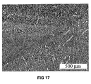
- Figure 15 is a photomacrograph of a two layer weld deposited section which is typical of the deposits for each of the sections. As can be seen, the deposit has a smooth, glossy surface which is substantially free of slag and which does not exhibit any surface cracks. Also, presentation of a magnet to the weld deposit does not exhibit any ferromagnetic attraction indicative of the presence of martensite.
- Figures 16 and 17 are photomicrographs respectively taken longitudinally and transversely with respect to a weld bead of the deposit.
- the weld deposit were substantially crack free.
- the microstructure is characterised by dendrites and a eutectic of M 7 C 3 and austenite and an absence of martensite at M 7 C 3 carbide and austenite interfaces.
- the M 7 C 3 carbide shows a low level of interconnectivity. Both powders resulted in excellent fluidity, while the level of dilution was good in being approximately 10 to 25%.
- the substrate preheat level required was much lower than used in current practice, at 150°C rather than about 300°C.
Priority Applications (1)
| Application Number | Priority Date | Filing Date | Title |
|---|---|---|---|
| EP11003390A EP2351865A1 (fr) | 2004-10-27 | 2004-10-27 | Alliage amélioré résistant à l'usure |
Applications Claiming Priority (1)
| Application Number | Priority Date | Filing Date | Title |
|---|---|---|---|
| EP11003390A EP2351865A1 (fr) | 2004-10-27 | 2004-10-27 | Alliage amélioré résistant à l'usure |
Related Parent Applications (1)
| Application Number | Title | Priority Date | Filing Date |
|---|---|---|---|
| EP04789619.6 Division | 2004-10-27 |
Publications (1)
| Publication Number | Publication Date |
|---|---|
| EP2351865A1 true EP2351865A1 (fr) | 2011-08-03 |
Family
ID=44246726
Family Applications (1)
| Application Number | Title | Priority Date | Filing Date |
|---|---|---|---|
| EP11003390A Withdrawn EP2351865A1 (fr) | 2004-10-27 | 2004-10-27 | Alliage amélioré résistant à l'usure |
Country Status (1)
| Country | Link |
|---|---|
| EP (1) | EP2351865A1 (fr) |
Cited By (2)
| Publication number | Priority date | Publication date | Assignee | Title |
|---|---|---|---|---|
| EP3720979A4 (fr) * | 2017-12-04 | 2021-07-07 | Weir Minerals Australia Ltd | Fontes blanches résilientes et résistantes à la corrosion |
| CN114807733A (zh) * | 2022-05-11 | 2022-07-29 | 长沙威尔保新材料有限公司 | 一种高铬白口抗磨铸铁部件与金属部件的连接固定的方法 |
Citations (5)
| Publication number | Priority date | Publication date | Assignee | Title |
|---|---|---|---|---|
| WO1984004760A1 (fr) * | 1983-05-30 | 1984-12-06 | Vickers Australia Ltd | Fer blanc hypereutectique dur, resistant a l'usure et a l'abrasion, a haute teneur en chrome |
| GB2153846A (en) * | 1984-02-04 | 1985-08-29 | Sheepbridge Equipment Limited | Cast iron alloy for grinding media |
| JPH0243342A (ja) * | 1988-08-03 | 1990-02-13 | Kubota Ltd | 高硬度オーステナイト鋳鉄 |
| US5803152A (en) | 1993-05-21 | 1998-09-08 | Warman International Limited | Microstructurally refined multiphase castings |
| US6375895B1 (en) | 2000-06-14 | 2002-04-23 | Att Technology, Ltd. | Hardfacing alloy, methods, and products |
-
2004
- 2004-10-27 EP EP11003390A patent/EP2351865A1/fr not_active Withdrawn
Patent Citations (6)
| Publication number | Priority date | Publication date | Assignee | Title |
|---|---|---|---|---|
| WO1984004760A1 (fr) * | 1983-05-30 | 1984-12-06 | Vickers Australia Ltd | Fer blanc hypereutectique dur, resistant a l'usure et a l'abrasion, a haute teneur en chrome |
| AU2886584A (en) | 1983-05-30 | 1984-12-06 | Vickers Australia Ltd. | High chromium white iron, manufacture thereof and its application to abrasion resistant composites |
| GB2153846A (en) * | 1984-02-04 | 1985-08-29 | Sheepbridge Equipment Limited | Cast iron alloy for grinding media |
| JPH0243342A (ja) * | 1988-08-03 | 1990-02-13 | Kubota Ltd | 高硬度オーステナイト鋳鉄 |
| US5803152A (en) | 1993-05-21 | 1998-09-08 | Warman International Limited | Microstructurally refined multiphase castings |
| US6375895B1 (en) | 2000-06-14 | 2002-04-23 | Att Technology, Ltd. | Hardfacing alloy, methods, and products |
Non-Patent Citations (1)
| Title |
|---|
| "High-Chromium White Irons", vol. 15, ASM HANDBOOK, pages: 681 |
Cited By (3)
| Publication number | Priority date | Publication date | Assignee | Title |
|---|---|---|---|---|
| EP3720979A4 (fr) * | 2017-12-04 | 2021-07-07 | Weir Minerals Australia Ltd | Fontes blanches résilientes et résistantes à la corrosion |
| CN114807733A (zh) * | 2022-05-11 | 2022-07-29 | 长沙威尔保新材料有限公司 | 一种高铬白口抗磨铸铁部件与金属部件的连接固定的方法 |
| CN114807733B (zh) * | 2022-05-11 | 2023-06-23 | 长沙威尔保新材料有限公司 | 一种高铬白口抗磨铸铁部件与金属部件的连接固定的方法 |
Similar Documents
| Publication | Publication Date | Title |
|---|---|---|
| AU2011201781B2 (en) | Improved wear resistant alloy | |
| EP3143175B1 (fr) | Alliages de fer blanc hypereutectiques contenant du vanadium, du chrome et de l'azote, et articles fabriqués à partir de ces alliages | |
| RU2156176C2 (ru) | Способ литья металлического сплава, содержащего первичную фазу, диспергированную в эвтектической фазе | |
| US7442261B2 (en) | Iron-base alloy containing chromium-tungsten carbide and a method of producing it | |
| EP2531630B1 (fr) | Matériaux à base de métal dur | |
| AU2014374832B2 (en) | Composite metal product | |
| KR100935816B1 (ko) | 내마모성이 우수한 무크롬 철계 경면처리 합금 | |
| Cao et al. | Microstructure evolutions of graded high-vanadium tool steel composite coating in-situ fabricated via atmospheric plasma beam alloying | |
| TWI642793B (zh) | Roller outer layer for rolling and composite roll for rolling | |
| EP2351866B1 (fr) | Alliage amélioré résistant à l'usure | |
| Zhang et al. | Effect of high entropy alloy as the interlayer on the interfacial microstructure and mechanical property of Al/steel bimetal by compound casting | |
| EP2351865A1 (fr) | Alliage amélioré résistant à l'usure | |
| KR101174534B1 (ko) | 개선된 내마모성 합금 | |
| EP0552194A1 (fr) | Cermet a base de nickel et de cobalt avec carbure de niobium disperse | |
| JP2022085966A (ja) | 圧延用ロール外層材及び圧延用複合ロール | |
| CN105132791B (zh) | 一种改良的防磨损合金 | |
| AU658371B2 (en) | Nickel or cobalt based cermet with dispersed niobium carbide | |
| CN115976390A (zh) | 镍基碳化钨复合合金粉及其应用以及镍基碳化钨复合涂层的制备方法 | |
| Yonghua et al. | Study on material design of plasma arc cladding for rapid prototyping Fe-based alloys | |
| KR20070017999A (ko) | 연성 코발트계 라베스 상 합금 |
Legal Events
| Date | Code | Title | Description |
|---|---|---|---|
| PUAI | Public reference made under article 153(3) epc to a published international application that has entered the european phase |
Free format text: ORIGINAL CODE: 0009012 |
|
| AC | Divisional application: reference to earlier application |
Ref document number: 1825013 Country of ref document: EP Kind code of ref document: P |
|
| AK | Designated contracting states |
Kind code of ref document: A1 Designated state(s): AT BE BG CH CY CZ DE DK EE ES FI FR GB GR HU IE IT LI LU MC NL PL PT RO SE SI SK TR |
|
| 17P | Request for examination filed |
Effective date: 20120201 |
|
| 17Q | First examination report despatched |
Effective date: 20121009 |
|
| GRAP | Despatch of communication of intention to grant a patent |
Free format text: ORIGINAL CODE: EPIDOSNIGR1 |
|
| GRAC | Information related to communication of intention to grant a patent modified |
Free format text: ORIGINAL CODE: EPIDOSCIGR1 |
|
| INTG | Intention to grant announced |
Effective date: 20140527 |
|
| GRAJ | Information related to disapproval of communication of intention to grant by the applicant or resumption of examination proceedings by the epo deleted |
Free format text: ORIGINAL CODE: EPIDOSDIGR1 |
|
| GRAP | Despatch of communication of intention to grant a patent |
Free format text: ORIGINAL CODE: EPIDOSNIGR1 |
|
| INTG | Intention to grant announced |
Effective date: 20140617 |
|
| INTG | Intention to grant announced |
Effective date: 20140709 |
|
| STAA | Information on the status of an ep patent application or granted ep patent |
Free format text: STATUS: THE APPLICATION IS DEEMED TO BE WITHDRAWN |
|
| 18D | Application deemed to be withdrawn |
Effective date: 20141120 |