EP2351642A1 - Resin bag production equipment - Google Patents
Resin bag production equipment Download PDFInfo
- Publication number
- EP2351642A1 EP2351642A1 EP08809616A EP08809616A EP2351642A1 EP 2351642 A1 EP2351642 A1 EP 2351642A1 EP 08809616 A EP08809616 A EP 08809616A EP 08809616 A EP08809616 A EP 08809616A EP 2351642 A1 EP2351642 A1 EP 2351642A1
- Authority
- EP
- European Patent Office
- Prior art keywords
- port
- bag body
- opening
- bonding
- bag
- Prior art date
- Legal status (The legal status is an assumption and is not a legal conclusion. Google has not performed a legal analysis and makes no representation as to the accuracy of the status listed.)
- Granted
Links
Images



Classifications
-
- B—PERFORMING OPERATIONS; TRANSPORTING
- B29—WORKING OF PLASTICS; WORKING OF SUBSTANCES IN A PLASTIC STATE IN GENERAL
- B29C—SHAPING OR JOINING OF PLASTICS; SHAPING OF MATERIAL IN A PLASTIC STATE, NOT OTHERWISE PROVIDED FOR; AFTER-TREATMENT OF THE SHAPED PRODUCTS, e.g. REPAIRING
- B29C66/00—General aspects of processes or apparatus for joining preformed parts
- B29C66/01—General aspects dealing with the joint area or with the area to be joined
- B29C66/05—Particular design of joint configurations
- B29C66/20—Particular design of joint configurations particular design of the joint lines, e.g. of the weld lines
- B29C66/24—Particular design of joint configurations particular design of the joint lines, e.g. of the weld lines said joint lines being closed or non-straight
- B29C66/244—Particular design of joint configurations particular design of the joint lines, e.g. of the weld lines said joint lines being closed or non-straight said joint lines being non-straight, e.g. forming non-closed contours
-
- B—PERFORMING OPERATIONS; TRANSPORTING
- B29—WORKING OF PLASTICS; WORKING OF SUBSTANCES IN A PLASTIC STATE IN GENERAL
- B29C—SHAPING OR JOINING OF PLASTICS; SHAPING OF MATERIAL IN A PLASTIC STATE, NOT OTHERWISE PROVIDED FOR; AFTER-TREATMENT OF THE SHAPED PRODUCTS, e.g. REPAIRING
- B29C65/00—Joining or sealing of preformed parts, e.g. welding of plastics materials; Apparatus therefor
- B29C65/02—Joining or sealing of preformed parts, e.g. welding of plastics materials; Apparatus therefor by heating, with or without pressure
- B29C65/18—Joining or sealing of preformed parts, e.g. welding of plastics materials; Apparatus therefor by heating, with or without pressure using heated tools
-
- B—PERFORMING OPERATIONS; TRANSPORTING
- B29—WORKING OF PLASTICS; WORKING OF SUBSTANCES IN A PLASTIC STATE IN GENERAL
- B29C—SHAPING OR JOINING OF PLASTICS; SHAPING OF MATERIAL IN A PLASTIC STATE, NOT OTHERWISE PROVIDED FOR; AFTER-TREATMENT OF THE SHAPED PRODUCTS, e.g. REPAIRING
- B29C65/00—Joining or sealing of preformed parts, e.g. welding of plastics materials; Apparatus therefor
- B29C65/74—Joining or sealing of preformed parts, e.g. welding of plastics materials; Apparatus therefor by welding and severing, or by joining and severing, the severing being performed in the area to be joined, next to the area to be joined, in the joint area or next to the joint area
- B29C65/743—Joining or sealing of preformed parts, e.g. welding of plastics materials; Apparatus therefor by welding and severing, or by joining and severing, the severing being performed in the area to be joined, next to the area to be joined, in the joint area or next to the joint area using the same tool for both joining and severing, said tool being monobloc or formed by several parts mounted together and forming a monobloc
- B29C65/7441—Joining or sealing of preformed parts, e.g. welding of plastics materials; Apparatus therefor by welding and severing, or by joining and severing, the severing being performed in the area to be joined, next to the area to be joined, in the joint area or next to the joint area using the same tool for both joining and severing, said tool being monobloc or formed by several parts mounted together and forming a monobloc for making welds and cuts of other than simple rectilinear form
-
- B—PERFORMING OPERATIONS; TRANSPORTING
- B29—WORKING OF PLASTICS; WORKING OF SUBSTANCES IN A PLASTIC STATE IN GENERAL
- B29C—SHAPING OR JOINING OF PLASTICS; SHAPING OF MATERIAL IN A PLASTIC STATE, NOT OTHERWISE PROVIDED FOR; AFTER-TREATMENT OF THE SHAPED PRODUCTS, e.g. REPAIRING
- B29C65/00—Joining or sealing of preformed parts, e.g. welding of plastics materials; Apparatus therefor
- B29C65/78—Means for handling the parts to be joined, e.g. for making containers or hollow articles, e.g. means for handling sheets, plates, web-like materials, tubular articles, hollow articles or elements to be joined therewith; Means for discharging the joined articles from the joining apparatus
- B29C65/7841—Holding or clamping means for handling purposes
- B29C65/7847—Holding or clamping means for handling purposes using vacuum to hold at least one of the parts to be joined
-
- B—PERFORMING OPERATIONS; TRANSPORTING
- B29—WORKING OF PLASTICS; WORKING OF SUBSTANCES IN A PLASTIC STATE IN GENERAL
- B29C—SHAPING OR JOINING OF PLASTICS; SHAPING OF MATERIAL IN A PLASTIC STATE, NOT OTHERWISE PROVIDED FOR; AFTER-TREATMENT OF THE SHAPED PRODUCTS, e.g. REPAIRING
- B29C66/00—General aspects of processes or apparatus for joining preformed parts
- B29C66/01—General aspects dealing with the joint area or with the area to be joined
- B29C66/02—Preparation of the material, in the area to be joined, prior to joining or welding
- B29C66/024—Thermal pre-treatments
- B29C66/0242—Heating, or preheating, e.g. drying
-
- B—PERFORMING OPERATIONS; TRANSPORTING
- B29—WORKING OF PLASTICS; WORKING OF SUBSTANCES IN A PLASTIC STATE IN GENERAL
- B29C—SHAPING OR JOINING OF PLASTICS; SHAPING OF MATERIAL IN A PLASTIC STATE, NOT OTHERWISE PROVIDED FOR; AFTER-TREATMENT OF THE SHAPED PRODUCTS, e.g. REPAIRING
- B29C66/00—General aspects of processes or apparatus for joining preformed parts
- B29C66/01—General aspects dealing with the joint area or with the area to be joined
- B29C66/03—After-treatments in the joint area
- B29C66/034—Thermal after-treatments
- B29C66/0342—Cooling, e.g. transporting through welding and cooling zone
-
- B—PERFORMING OPERATIONS; TRANSPORTING
- B29—WORKING OF PLASTICS; WORKING OF SUBSTANCES IN A PLASTIC STATE IN GENERAL
- B29C—SHAPING OR JOINING OF PLASTICS; SHAPING OF MATERIAL IN A PLASTIC STATE, NOT OTHERWISE PROVIDED FOR; AFTER-TREATMENT OF THE SHAPED PRODUCTS, e.g. REPAIRING
- B29C66/00—General aspects of processes or apparatus for joining preformed parts
- B29C66/01—General aspects dealing with the joint area or with the area to be joined
- B29C66/05—Particular design of joint configurations
- B29C66/10—Particular design of joint configurations particular design of the joint cross-sections
- B29C66/11—Joint cross-sections comprising a single joint-segment, i.e. one of the parts to be joined comprising a single joint-segment in the joint cross-section
- B29C66/112—Single lapped joints
- B29C66/1122—Single lap to lap joints, i.e. overlap joints
-
- B—PERFORMING OPERATIONS; TRANSPORTING
- B29—WORKING OF PLASTICS; WORKING OF SUBSTANCES IN A PLASTIC STATE IN GENERAL
- B29C—SHAPING OR JOINING OF PLASTICS; SHAPING OF MATERIAL IN A PLASTIC STATE, NOT OTHERWISE PROVIDED FOR; AFTER-TREATMENT OF THE SHAPED PRODUCTS, e.g. REPAIRING
- B29C66/00—General aspects of processes or apparatus for joining preformed parts
- B29C66/01—General aspects dealing with the joint area or with the area to be joined
- B29C66/345—Progressively making the joint, e.g. starting from the middle
- B29C66/3452—Making complete joints by combining partial joints
-
- B—PERFORMING OPERATIONS; TRANSPORTING
- B29—WORKING OF PLASTICS; WORKING OF SUBSTANCES IN A PLASTIC STATE IN GENERAL
- B29C—SHAPING OR JOINING OF PLASTICS; SHAPING OF MATERIAL IN A PLASTIC STATE, NOT OTHERWISE PROVIDED FOR; AFTER-TREATMENT OF THE SHAPED PRODUCTS, e.g. REPAIRING
- B29C66/00—General aspects of processes or apparatus for joining preformed parts
- B29C66/40—General aspects of joining substantially flat articles, e.g. plates, sheets or web-like materials; Making flat seams in tubular or hollow articles; Joining single elements to substantially flat surfaces
- B29C66/41—Joining substantially flat articles ; Making flat seams in tubular or hollow articles
- B29C66/43—Joining a relatively small portion of the surface of said articles
- B29C66/431—Joining the articles to themselves
-
- B—PERFORMING OPERATIONS; TRANSPORTING
- B29—WORKING OF PLASTICS; WORKING OF SUBSTANCES IN A PLASTIC STATE IN GENERAL
- B29C—SHAPING OR JOINING OF PLASTICS; SHAPING OF MATERIAL IN A PLASTIC STATE, NOT OTHERWISE PROVIDED FOR; AFTER-TREATMENT OF THE SHAPED PRODUCTS, e.g. REPAIRING
- B29C66/00—General aspects of processes or apparatus for joining preformed parts
- B29C66/40—General aspects of joining substantially flat articles, e.g. plates, sheets or web-like materials; Making flat seams in tubular or hollow articles; Joining single elements to substantially flat surfaces
- B29C66/41—Joining substantially flat articles ; Making flat seams in tubular or hollow articles
- B29C66/43—Joining a relatively small portion of the surface of said articles
- B29C66/431—Joining the articles to themselves
- B29C66/4312—Joining the articles to themselves for making flat seams in tubular or hollow articles, e.g. transversal seams
- B29C66/43121—Closing the ends of tubular or hollow single articles, e.g. closing the ends of bags
-
- B—PERFORMING OPERATIONS; TRANSPORTING
- B29—WORKING OF PLASTICS; WORKING OF SUBSTANCES IN A PLASTIC STATE IN GENERAL
- B29C—SHAPING OR JOINING OF PLASTICS; SHAPING OF MATERIAL IN A PLASTIC STATE, NOT OTHERWISE PROVIDED FOR; AFTER-TREATMENT OF THE SHAPED PRODUCTS, e.g. REPAIRING
- B29C66/00—General aspects of processes or apparatus for joining preformed parts
- B29C66/50—General aspects of joining tubular articles; General aspects of joining long products, i.e. bars or profiled elements; General aspects of joining single elements to tubular articles, hollow articles or bars; General aspects of joining several hollow-preforms to form hollow or tubular articles
- B29C66/51—Joining tubular articles, profiled elements or bars; Joining single elements to tubular articles, hollow articles or bars; Joining several hollow-preforms to form hollow or tubular articles
- B29C66/53—Joining single elements to tubular articles, hollow articles or bars
- B29C66/532—Joining single elements to the wall of tubular articles, hollow articles or bars
- B29C66/5326—Joining single elements to the wall of tubular articles, hollow articles or bars said single elements being substantially flat
- B29C66/53261—Enclosing tubular articles between substantially flat elements
- B29C66/53262—Enclosing spouts between the walls of bags, e.g. of medical bags
-
- B—PERFORMING OPERATIONS; TRANSPORTING
- B29—WORKING OF PLASTICS; WORKING OF SUBSTANCES IN A PLASTIC STATE IN GENERAL
- B29C—SHAPING OR JOINING OF PLASTICS; SHAPING OF MATERIAL IN A PLASTIC STATE, NOT OTHERWISE PROVIDED FOR; AFTER-TREATMENT OF THE SHAPED PRODUCTS, e.g. REPAIRING
- B29C66/00—General aspects of processes or apparatus for joining preformed parts
- B29C66/80—General aspects of machine operations or constructions and parts thereof
- B29C66/81—General aspects of the pressing elements, i.e. the elements applying pressure on the parts to be joined in the area to be joined, e.g. the welding jaws or clamps
- B29C66/814—General aspects of the pressing elements, i.e. the elements applying pressure on the parts to be joined in the area to be joined, e.g. the welding jaws or clamps characterised by the design of the pressing elements, e.g. of the welding jaws or clamps
- B29C66/8141—General aspects of the pressing elements, i.e. the elements applying pressure on the parts to be joined in the area to be joined, e.g. the welding jaws or clamps characterised by the design of the pressing elements, e.g. of the welding jaws or clamps characterised by the surface geometry of the part of the pressing elements, e.g. welding jaws or clamps, coming into contact with the parts to be joined
- B29C66/81431—General aspects of the pressing elements, i.e. the elements applying pressure on the parts to be joined in the area to be joined, e.g. the welding jaws or clamps characterised by the design of the pressing elements, e.g. of the welding jaws or clamps characterised by the surface geometry of the part of the pressing elements, e.g. welding jaws or clamps, coming into contact with the parts to be joined comprising a single cavity, e.g. a groove
-
- B—PERFORMING OPERATIONS; TRANSPORTING
- B29—WORKING OF PLASTICS; WORKING OF SUBSTANCES IN A PLASTIC STATE IN GENERAL
- B29C—SHAPING OR JOINING OF PLASTICS; SHAPING OF MATERIAL IN A PLASTIC STATE, NOT OTHERWISE PROVIDED FOR; AFTER-TREATMENT OF THE SHAPED PRODUCTS, e.g. REPAIRING
- B29C66/00—General aspects of processes or apparatus for joining preformed parts
- B29C66/80—General aspects of machine operations or constructions and parts thereof
- B29C66/81—General aspects of the pressing elements, i.e. the elements applying pressure on the parts to be joined in the area to be joined, e.g. the welding jaws or clamps
- B29C66/818—General aspects of the pressing elements, i.e. the elements applying pressure on the parts to be joined in the area to be joined, e.g. the welding jaws or clamps characterised by the cooling constructional aspects, or by the thermal or electrical insulating or conducting constructional aspects of the welding jaws or of the clamps ; comprising means for compensating for the thermal expansion of the welding jaws or of the clamps
- B29C66/8181—General aspects of the pressing elements, i.e. the elements applying pressure on the parts to be joined in the area to be joined, e.g. the welding jaws or clamps characterised by the cooling constructional aspects, or by the thermal or electrical insulating or conducting constructional aspects of the welding jaws or of the clamps ; comprising means for compensating for the thermal expansion of the welding jaws or of the clamps characterised by the cooling constructional aspects
-
- B—PERFORMING OPERATIONS; TRANSPORTING
- B29—WORKING OF PLASTICS; WORKING OF SUBSTANCES IN A PLASTIC STATE IN GENERAL
- B29C—SHAPING OR JOINING OF PLASTICS; SHAPING OF MATERIAL IN A PLASTIC STATE, NOT OTHERWISE PROVIDED FOR; AFTER-TREATMENT OF THE SHAPED PRODUCTS, e.g. REPAIRING
- B29C66/00—General aspects of processes or apparatus for joining preformed parts
- B29C66/80—General aspects of machine operations or constructions and parts thereof
- B29C66/82—Pressure application arrangements, e.g. transmission or actuating mechanisms for joining tools or clamps
- B29C66/824—Actuating mechanisms
- B29C66/8242—Pneumatic or hydraulic drives
-
- B—PERFORMING OPERATIONS; TRANSPORTING
- B29—WORKING OF PLASTICS; WORKING OF SUBSTANCES IN A PLASTIC STATE IN GENERAL
- B29C—SHAPING OR JOINING OF PLASTICS; SHAPING OF MATERIAL IN A PLASTIC STATE, NOT OTHERWISE PROVIDED FOR; AFTER-TREATMENT OF THE SHAPED PRODUCTS, e.g. REPAIRING
- B29C66/00—General aspects of processes or apparatus for joining preformed parts
- B29C66/80—General aspects of machine operations or constructions and parts thereof
- B29C66/83—General aspects of machine operations or constructions and parts thereof characterised by the movement of the joining or pressing tools
- B29C66/832—Reciprocating joining or pressing tools
- B29C66/8322—Joining or pressing tools reciprocating along one axis
- B29C66/83221—Joining or pressing tools reciprocating along one axis cooperating reciprocating tools, each tool reciprocating along one axis
-
- B—PERFORMING OPERATIONS; TRANSPORTING
- B29—WORKING OF PLASTICS; WORKING OF SUBSTANCES IN A PLASTIC STATE IN GENERAL
- B29C—SHAPING OR JOINING OF PLASTICS; SHAPING OF MATERIAL IN A PLASTIC STATE, NOT OTHERWISE PROVIDED FOR; AFTER-TREATMENT OF THE SHAPED PRODUCTS, e.g. REPAIRING
- B29C66/00—General aspects of processes or apparatus for joining preformed parts
- B29C66/80—General aspects of machine operations or constructions and parts thereof
- B29C66/84—Specific machine types or machines suitable for specific applications
- B29C66/843—Machines for making separate joints at the same time in different planes; Machines for making separate joints at the same time mounted in parallel or in series
- B29C66/8432—Machines for making separate joints at the same time mounted in parallel or in series
-
- B—PERFORMING OPERATIONS; TRANSPORTING
- B29—WORKING OF PLASTICS; WORKING OF SUBSTANCES IN A PLASTIC STATE IN GENERAL
- B29C—SHAPING OR JOINING OF PLASTICS; SHAPING OF MATERIAL IN A PLASTIC STATE, NOT OTHERWISE PROVIDED FOR; AFTER-TREATMENT OF THE SHAPED PRODUCTS, e.g. REPAIRING
- B29C66/00—General aspects of processes or apparatus for joining preformed parts
- B29C66/80—General aspects of machine operations or constructions and parts thereof
- B29C66/84—Specific machine types or machines suitable for specific applications
- B29C66/851—Bag or container making machines
- B29C66/8511—Bag making machines
-
- B—PERFORMING OPERATIONS; TRANSPORTING
- B29—WORKING OF PLASTICS; WORKING OF SUBSTANCES IN A PLASTIC STATE IN GENERAL
- B29C—SHAPING OR JOINING OF PLASTICS; SHAPING OF MATERIAL IN A PLASTIC STATE, NOT OTHERWISE PROVIDED FOR; AFTER-TREATMENT OF THE SHAPED PRODUCTS, e.g. REPAIRING
- B29C35/00—Heating, cooling or curing, e.g. crosslinking or vulcanising; Apparatus therefor
- B29C35/02—Heating or curing, e.g. crosslinking or vulcanizing during moulding, e.g. in a mould
- B29C35/04—Heating or curing, e.g. crosslinking or vulcanizing during moulding, e.g. in a mould using liquids, gas or steam
- B29C35/045—Heating or curing, e.g. crosslinking or vulcanizing during moulding, e.g. in a mould using liquids, gas or steam using gas or flames
- B29C2035/046—Heating or curing, e.g. crosslinking or vulcanizing during moulding, e.g. in a mould using liquids, gas or steam using gas or flames dried air
-
- B—PERFORMING OPERATIONS; TRANSPORTING
- B29—WORKING OF PLASTICS; WORKING OF SUBSTANCES IN A PLASTIC STATE IN GENERAL
- B29C—SHAPING OR JOINING OF PLASTICS; SHAPING OF MATERIAL IN A PLASTIC STATE, NOT OTHERWISE PROVIDED FOR; AFTER-TREATMENT OF THE SHAPED PRODUCTS, e.g. REPAIRING
- B29C2793/00—Shaping techniques involving a cutting or machining operation
- B29C2793/0054—Shaping techniques involving a cutting or machining operation partially cutting through the material
-
- B—PERFORMING OPERATIONS; TRANSPORTING
- B29—WORKING OF PLASTICS; WORKING OF SUBSTANCES IN A PLASTIC STATE IN GENERAL
- B29C—SHAPING OR JOINING OF PLASTICS; SHAPING OF MATERIAL IN A PLASTIC STATE, NOT OTHERWISE PROVIDED FOR; AFTER-TREATMENT OF THE SHAPED PRODUCTS, e.g. REPAIRING
- B29C66/00—General aspects of processes or apparatus for joining preformed parts
- B29C66/80—General aspects of machine operations or constructions and parts thereof
- B29C66/81—General aspects of the pressing elements, i.e. the elements applying pressure on the parts to be joined in the area to be joined, e.g. the welding jaws or clamps
- B29C66/814—General aspects of the pressing elements, i.e. the elements applying pressure on the parts to be joined in the area to be joined, e.g. the welding jaws or clamps characterised by the design of the pressing elements, e.g. of the welding jaws or clamps
- B29C66/8141—General aspects of the pressing elements, i.e. the elements applying pressure on the parts to be joined in the area to be joined, e.g. the welding jaws or clamps characterised by the design of the pressing elements, e.g. of the welding jaws or clamps characterised by the surface geometry of the part of the pressing elements, e.g. welding jaws or clamps, coming into contact with the parts to be joined
- B29C66/81411—General aspects of the pressing elements, i.e. the elements applying pressure on the parts to be joined in the area to be joined, e.g. the welding jaws or clamps characterised by the design of the pressing elements, e.g. of the welding jaws or clamps characterised by the surface geometry of the part of the pressing elements, e.g. welding jaws or clamps, coming into contact with the parts to be joined characterised by its cross-section, e.g. transversal or longitudinal, being non-flat
- B29C66/81421—General aspects of the pressing elements, i.e. the elements applying pressure on the parts to be joined in the area to be joined, e.g. the welding jaws or clamps characterised by the design of the pressing elements, e.g. of the welding jaws or clamps characterised by the surface geometry of the part of the pressing elements, e.g. welding jaws or clamps, coming into contact with the parts to be joined characterised by its cross-section, e.g. transversal or longitudinal, being non-flat being convex or concave
- B29C66/81423—General aspects of the pressing elements, i.e. the elements applying pressure on the parts to be joined in the area to be joined, e.g. the welding jaws or clamps characterised by the design of the pressing elements, e.g. of the welding jaws or clamps characterised by the surface geometry of the part of the pressing elements, e.g. welding jaws or clamps, coming into contact with the parts to be joined characterised by its cross-section, e.g. transversal or longitudinal, being non-flat being convex or concave being concave
-
- B—PERFORMING OPERATIONS; TRANSPORTING
- B31—MAKING ARTICLES OF PAPER, CARDBOARD OR MATERIAL WORKED IN A MANNER ANALOGOUS TO PAPER; WORKING PAPER, CARDBOARD OR MATERIAL WORKED IN A MANNER ANALOGOUS TO PAPER
- B31B—MAKING CONTAINERS OF PAPER, CARDBOARD OR MATERIAL WORKED IN A MANNER ANALOGOUS TO PAPER
- B31B70/00—Making flexible containers, e.g. envelopes or bags
- B31B70/74—Auxiliary operations
- B31B70/81—Forming or attaching accessories, e.g. opening devices, closures or tear strings
- B31B70/84—Forming or attaching means for filling or dispensing contents, e.g. valves or spouts
- B31B70/844—Applying rigid valves, spouts, or filling tubes
Definitions
- the present invention relates to resin bag manufacturing equipment for manufacturing a resin bag used as a container for a fluid such as a drip-feed solution.
- Resin bags are used as containers for a liquid such as a drip-feed solution.
- a resin bag is formed of a soft resin film or the like and made up of a bag-shaped bag body having an opening at one side and a tubular port attached to the opening.
- the tubular port is made of hard resin and serves as a mouth through which a liquid is charged/discharged into/from the bag.
- such a resin bag is made by setting a port between two ribbon-shaped films, bonding these two films and at the same time bonding the films and port in the opening with the port interposed between the two films (for example, see Patent Document 1).
- the above described conventional manufacturing method involves problems like producing wrinkles in the film around the bonded part between the films and port, which spoils the appearance, and the films being drawn and preventing secure bonding, which results in insufficient sealing strength or appearance of a gap between the films and port.
- One of the causes of such problems is that since bonding between the films along the outside shape of the container and bonding between the films and port are performed simultaneously, the length of the film is not enough to wrap around the entire perimeter of the round port, it is difficult to set an optimal temperature condition for bonding of both parts, and as a result, it is difficult to stabilize bonding quality of both parts.
- Patent Document 1 cuts the film along the outside shape of the container in addition to bonding between the films along the outside shape of the container and bonding between the films and port, which complicates a die for bonding and cutting and makes it difficult to optimally set not only the bonding condition but also the cutting condition.
- Another cause is that while bonding between the films along the outside shape of the container is two-dimensional bonding, bonding between the films and port is three-dimensional bonding, and therefore when the die for bonding is pressed against the neighborhood of the boundary between the two-dimensional bonding part and the three-dimensional bonding part, the films are drawn and become thinner or wrinkles easily occur in the films.
- the present invention has been accomplished based on such technical problems and it is an object of the present invention to provide resin bag manufacturing equipment capable of manufacturing a resin bag reliably and with high quality.
- the resin bag manufacturing equipment of the present invention is resin bag manufacturing equipment for manufacturing a resin bag into which a fluid is charged, including a bag body bonding apparatus that forms an opening at only one side of a pair of films unreeled from a roll and bonds a remaining entire perimeter to form a bag body, a cutting apparatus that cuts the films along an outside shape of the bag body, an opener that opens the opening of the bag body, and a port bonding apparatus that inserts a tubular port into the opening formed by the opener and bonds the opening and the port.
- the bag body bonding apparatus forms an opening only at one side of the films, bonds the remaining entire perimeter and forms the bag body, and therefore this bonding is two-dimensional bonding, makes the films less wrinkled and allows the films to be bonded without being drawn.
- the port bonding apparatus needs only to perform three-dimensional bonding with the port inserted into the opening of the bag body, and since the films are pushed widthwise in the direction orthogonal to the axial line of the tubular port, the films are hardly wrinkled even with three-dimensional bonding, preventing the film from becoming thinner.
- the port bonding apparatus inserts the port into the opening formed by the opener, it is possible to automate the entire process of manufacturing the resin bag.
- the opener is provided with a pair of plate members that is pressed against both sides of the opening and clamps the bag body on both sides of the opening from both surfaces of the bag body and a widthwise approaching mechanism that moves the plate members on both sides of the opening to a central portion of the opening while pressing the plate members against the bag body and opens the opening. In this way, the opening can be opened by pushing the opening from both sides.
- the opener can also be provided with a suction cup that suctions the bag body in a central portion of the pair of plate members and a suction cup drive mechanism that lifts the suction cup away from the surface of the bag body. Lifting the suction cup that suctions the bag body in the central portion with the pair of plate members pressed against the bag body allows the opening to be opened more reliably.
- the resin bag manufacturing equipment of the present invention can be further provided with a bag body transfer apparatus that transfers the bag body from the bag body bonding apparatus to the opener.
- the bag body transfer apparatus is provided with a flat plate to be inserted into the opening and a clamp member that clamps the bag body from both surfaces and the bag body bonding apparatus performs bonding with the plate inserted between the pair of films.
- the plate Since bonding is conducted with the plate inserted between the films, the plate remains inserted in the opening after the bonding. Clamping the bag body using the clamp member allows the bag body to be held. When the plate is inserted into the opening after the bag body is formed, the opening needs to be opened and it is easily estimable that this may complicate the mechanism and cause the opening not to be opened reliably. By adopting the above described configuration, it is possible to avoid such a problem and speedily transfer the bag body using the bag body transfer apparatus.
- leaving the plate inserted in the opening can prevent both sides of the films from sticking to each other in the middle of the process and allows the opener to easily open the opening in a post-process.
- the clamp member is adapted so as to clamp the bag body from both sides of the plate inserted into the opening and to be provided with a protrusion dug into the bag body, it is possible to form a protrusion in the film at the opening. By doing so, it is possible to prevent both sides of the films of the opening from sticking to each other and this also allows the opener to easily open the opening in a post-process.
- the resin bag manufacturing equipment of the present invention can further be provided with a port transfer apparatus that transfers the port to be inserted into the opening of the bag body by the port bonding apparatus.
- This port transfer apparatus is provided with a port holder in which the tubular port is inserted and held.
- the port bonding apparatus inserts the port held by the port holder into the opening of the bag body opened by the opener and performs bonding.
- the port transfer apparatus transfers the bag body where the opening and the port are bonded to a post-process while holding the port.
- a port preheater can further be provided which preheats the port held by the port holder of the port transfer apparatus before transferring the port to the port bonding apparatus.
- the port preheater is preferably provided with a port rotation mechanism that rotates the port holder holding the port. This allows the entire perimeter of the port to be uniformly preheated. Any configuration may be adopted for the port rotation mechanism, but a configuration capable of rotating the port holder only when preheating is conducted is preferable taking into consideration that the port will be held and transferred to a post-process. Therefore, the port holder may be provided with a gear and a roller and the port preheater may be provided with a drive gear and a drive roller to rotate this gear and roller and the port holder may be rotated by pressing the drive gear and the drive roller against the gear and roller of the port holder.
- the bag body bonding apparatus and the cutting apparatus share a die having a bonding part that bonds the film and a cutting part that cuts the film, which is preferable from the standpoint of the die manufacturing cost.
- the cutting part preferably cuts the film by leaving a portion of the film in a thickness direction instead of completely cutting the film and keeps the mutually neighboring bag bodies connected. This eliminates the necessity for severely adjusting the cutting condition for the cutting part as in the case of completely cutting the film and attention may be focused on a setting of the bonding condition for the bonding part, and it is thereby possible to reduce time and trouble of adjustment and cost or the like.
- a separator may be provided in a post-process of the cutting apparatus to separate the mutually neighboring bag bodies which are connected through the portion of the film in the thickness direction.
- the bag body bonding apparatus forms an opening at only one side of the films and bonds the remaining entire perimeter to form a bag body, which makes bonding two-dimensional bonding and prevents the film from being easily wrinkled. Furthermore, the port bonding apparatus performs bonding on the opening of the bag body and needs only to conduct three-dimensional bonding with the port inserted in the opening, and since the bonding line is orthogonal to the axial line of the tubular port, even three-dimensional bonding produces fewer wrinkles in the film.
- the respective sections allow bonding to be conducted under optimal conditions, and it is thereby possible to prevent the film from being wrinkled around the bonded part between the bag body and the port, prevent the appearance from being spoiled and prevent gaps from being produced due to a failure of reliable bonding and manufacture a resin bag reliably and with high quality.
- the opening of the bag body formed by the bag body bonding apparatus since the port is inserted by the port bonding apparatus into the opening opened by the opener, it is possible to automate the entire process of manufacturing a resin bag.
- the opening can be reliably opened by the opener by moving the plate members toward the central portion of the opening with the plate members pressed against both sides of the opening, suctioning the bag body in an intermediate part between the pair of plate members, inserting the plate between the two films when forming the bag body and forming a protrusion in the film.
- the cutting part preferably does not completely cut the film but cuts the film leaving a portion in the thickness direction of the film and keeps the mutually neighboring bag bodies connected. This eliminates the necessity for severely adjusting the cutting condition by the cutting part as in the case of completely cutting the film and attention may be focused on a setting of the bonding condition for the bonding part, and it is thereby possible to reduce time and trouble of adjustment and cost or the like.
- FIG. 1 illustrates a schematic configuration of resin bag manufacturing equipment 10 according to an embodiment of the present invention.
- the resin bag manufacturing equipment 10 is provided with a film feeder 20 that feeds a ribbon-shaped film F, a bonding/cutting apparatus (bag body bonding apparatus, cutting apparatus) 30 that bonds three sides of the film F fed from the film feeder 20 and cuts the film F along an outside shape of the resin bag, a cooler/remover 40 that cools the bonded part by the bonding/cutting apparatus 30 and removes unnecessary portions from the film F, a bag separator (separation apparatus) 50 that separates the film F at cutting parts into individual bag bodies 100, an opener 60 that opens one side not bonded of the separated bag bodies 100, a port transfer apparatus 70 that supplies a port 200 to an opening 101 of the bag body 100 made by the opener 60, a port bonding apparatus 80 that bonds the port 200 supplied from the port transfer apparatus 70 to the opening 101 of the bag body 100 and a port cooler 90 that cools the bonded part between the bag body 100 and the port 200 in that order.
- a film feeder 20 that feeds a ribbon-shaped film F
- the film feeder 20 is provided with a raw film material roller 22 that holds a raw film material roll (roll) 21 of a two-ply ribbon-shaped film F, a nip roller 23 that unreels the film F from the raw film material roll 21, a dancer roll 24 that gives/adjusts tension of the unreeled film F and a backward dancer roll 25 for causing the film F to retrocede in the direction opposite to the unreeling direction by making the film F move up and down in the direction orthogonal to the surface of the film F by an air cylinder 25a.
- the bonding/cutting apparatus 30 is provided with a pair of dies 31A and 31B located above and below the film F and a die drive mechanism (not shown) that drives the dies 31A and 31B to move up and down.
- the dies 31A and 31B are provided with a bonding part 32 that bonds three sides of the bag body 100 other than the opening 101 for bonding the port 200 and a cutting part 33 that cuts the film F along the outside shape of the bag body 100 on the perimeter side of the bonding part 32.
- one set of dies 31A and 31B are provided with the bonding parts 32 and cutting parts 33 corresponding to six bag bodies 100.
- the bonding part 32 and cutting part 33 have a convex shape protruding from the dies 31A and 31B, are heated by a heater and bond and cut two films F respectively when pressed against the films F.
- the cutting part 33 does not completely cut the film F but leaves a portion in the thickness direction thereof uncut. In this way, the mutually neighboring bag bodies 100, 100 are not separated from each other and transferred to a post-process as one connected piece.
- a bag body transfer apparatus 11 is provided facing the bonding/cutting apparatus 30.
- the bag body transfer apparatus 11 has an endless belt 12 provided with a plurality of clamp units 13 located at predetermined intervals. Each clamp unit 13 moves along the orbit of the belt 12 by driving the belt 12 to circulate using a motor (not shown) or the like.
- the clamp unit 13 is constructed of a flat plate 14 to be inserted into the opening 101 with which the port 200 is bonded in a post-process for the bag body 100 bonded by the bonding/cutting apparatus 30, a pair of clamp members 15A and 15B (see FIG. 2 for the clamp member 15B) that clamp the bag body 100 so as to sandwich the plate 14 when the plate 14 is inserted into the opening 101 and a drive section 16 that drives these clamp members 15A and 15B to open or close.
- the clamp members 15A and 15B are provided with pointed protrusions 17, 17 and when the clamp members 15A and 15B are closed and the bag body 100 is clamped, these protrusions 17, 17 are designed to dig into the bag body 100.
- convex parts which form convex shapes in mutually facing directions are formed in the two films F by the protrusions 17, 17, which prevents the two films F from sticking to each other when the plate 14 is pulled out later and which makes it possible to easily open the opening 101 in a post-process. Furthermore, when the protrusions 17, 17 are dug into the bag body 100, the bag body 100 can be reliably clamped and held.
- a guide 18 is provided upstream of the bonding/cutting apparatus 30 to make a gap between the two films F, F of the two-ply film F. Downstream of the guide 18, the plate 14 is inserted into the gap formed between the two films F, F by the guide 18.
- Such clamp units 13 clamp the film F when the bonding/cutting apparatus 30 bonds and cuts three sides of the film F. That is, the clamp units 13 are provided at an interval corresponding to the pitch of six bag bodies 100 between the dies 31A and 31B.
- such a bag body transfer apparatus 11 is provided with the belt 12 along these apparatuses so as to transfer the bag body 100 from the bonding/cutting apparatus 30 to the opener 60.
- the cooler/remover 40 cools the bag body 100 and fixes the bonded part.
- various appropriate techniques can be adopted such as pressing a plate cooled by a refrigerant such as a liquid against the bag body 100 or spraying a gas such as air.
- the cooler/remover 40 removes unnecessary parts other than the bag body 100 from the film F. Removal of the unnecessary parts can be done by gripping the unnecessary parts of the film F using a chuck member (not shown) or the like and pulling out the unnecessary parts using a cylinder apparatus or the like. The removed film F is ejected at an appropriate location by opening the chuck member.
- the hole is formed by the bonding/cutting apparatus 30 in a preceding process simultaneously with the bonding and cutting and the hole is pierced by a needle 41 at the cooler/remover 40 to remove the portion corresponding to the hole.
- the bag separator 50 separates the plurality of bag bodies 100 which are connected to each other by portions remaining in the thickness direction into the individual bag bodies 100. Separation is performed by clamping the individual bag bodies 100 using clamping plates 51, pushing up flat separators 52 between the mutually neighboring bag bodies 100, 100, further moving the backward dancer roll 25 through the air cylinder 25a in the direction orthogonal to the surface of the film F, causing the film F to retrocede toward the raw film material roll 21 and pulling the film F, and thereby cutting the portion in the thickness direction of the film F remaining between the mutually neighboring bag bodies 100, 100.
- the opener 60 holds the separated bag body 100 and opens the opening 101 which is the non-bonded part of the bag body 100.
- an upper frame 61A and a lower frame 61B are arranged substantially in parallel so as to be located above and below the bag body 100 transferred by the bag body transfer apparatus 11.
- the upper frame 61A and lower frame 61B are moved closer to or away from each other in the vertical direction by a nip cylinder 62.
- a pair of plate members 63, 63 and a suction cup 64 are provided on the under side at an end of the upper frame 61A and the upper side at an end of the lower frame 61B respectively.
- the upper and lower plate members 63, 63 are arranged so as to be pressed against both sides of the opening 101 of the bag body 100 respectively and the upper and lower plate members 63, 63 can clamp the bag body 100 from both sides of the opening 101 when the nip cylinder 62 causes the upper frame 61A and lower frame 61B to come closer to each other.
- the upper and lower plate members 63, 63 are provided on arms 65, 65 that pivot around bases 65a, 65a respectively, and a drive mechanism (widthwise approaching mechanism) 66 made up of an air cylinder 66a and a link mechanism 66b causes the arms 65, 65 to pivot synchronously to thereby cause the plate members 63, 63 to move closer to or away from each other. That is, the opening 101 can be opened by rotating the arms 65, 65 in a direction in which the plate members 63, 63 come closer to each other when the opening 101 of the bag body 100 is clamped.
- a drive mechanism widthwise approaching mechanism
- the suction cups 64 are intermediate parts between the pair of plate members 63, 63 and arranged so as to face each other in the vicinity of an end of the film of the opening 101 of the bag body 100 transferred by the bag body transfer apparatus 11.
- the suction cups 64 located above and below are moved up and down by air cylinders (suction cup drive mechanisms) 67 and the opening 101 is opened when the upper and lower suction cups 64, 64 move away from each other while suctioning the opening 101 of the bag body 100.
- the above described upper frame 61A and lower frame 61B can be moved forward or backward by a traveling cylinder 68 in the direction orthogonal to the direction in which the bag body 100 is transferred by the bag body transfer apparatus 11.
- the upper frame 61A and lower frame 61B are provided in correspondence with the dies 31A and 31B.
- the upper frame 61A and lower frame 61B are movable along a guide (not shown) between a position facing the bag body transfer apparatus 11 and the port bonding apparatus 80.
- the upper frame 61A and the lower frame 61B are first moved forward (direction shown by the arrow in the figure) by the traveling cylinder 68 in FIG. 4 with respect to the bag body 100 held by the clamp unit 13 of the bag body transfer apparatus 11 and the upper and lower plate members 63, 63 are made to face the opening 101 above and below.
- the nip cylinder 62 in FIG. 4 causes the upper frame 61A and the lower frame 61B to move closer to each other and the upper and lower plate members 63, 63 clamp the bag body 100. After the clamping by the upper and lower plate members 63, 63, the clamping of the bag body 100 by the clamp members 15A, 15B of the clamp unit 13 is released.
- the upper frame 61A and the lower frame 61B are moved backward by the traveling cylinder 68 in FIG. 4 and the bag body 100 held by the upper and lower plate members 63, 63 is detached from the clamp unit 13 of the bag body transfer apparatus 11. This causes the bag body 100 to be transferred from the clamp unit 13 to the opener 60.
- the suction cups 64 are made to suction the bag body 100 through the upper and lower air cylinders 67.
- the upper frame 61A and the lower frame 61B are moved from the position facing the bag body transfer apparatus 11 to the port bonding apparatus 80.
- the arms 65, 65 are rotated in the direction in which the upper and lower plate members 63, 63 come closer to each other to realize widthwise approaching, the upper and lower suction cups 64 are moved away from each other by the air cylinders 67 to open the opening 101.
- the port 200 is supplied from the port transfer apparatus 70 to the bag body 100 held by the opener 60 as described above and transferred to the port bonding apparatus 80 with the opening 101 left open.
- the port transfer apparatus 70 is provided with a plurality of holder units 72 on an endless belt 71 at predetermined intervals. Each holder unit 72 is moved along the orbit of the belt 71 by driving the belt 71 to circulate using a motor (not shown) or the like.
- each holder unit 72 is provided with a port holder 73 having an insertion hole (not shown) through which the port 200 is supplied by a port feeder (not shown).
- a pair of clamp members 74A, 74B for clamping the bag body 100 with which the port 200 is bonded and drive sections 75 for driving the clamp members 74A, 74B to open or close.
- the port 200 supplied from the port feeder (not shown) is inserted into the port holder 73.
- Each holder unit 72 transfers the port 200 held to a post-process along the orbit of the belt 71 through the circulation driving of the belt 71.
- the port 200 transferred by the holder unit 72 is first transferred to a port preheater 76.
- the port preheater 76 is provided with an air heater 77 that jets hot air to preheat the port 200 held by the holder unit 72 and a port rotation mechanism 78 that rotates the port holder 73 holding the port 200.
- a plate 78a is provided with a gear 78b, a motor 78c that drives the gear 78b to rotate, pulleys 78d, 78e and a belt 78f to transmit the torque of the motor 78c to the gear 78b and this plate 78a is driven by an air cylinder 78g to move in the vertical direction.
- the holder unit 72 is provided with the aforementioned port holder 73 in a manner pivotable around the axis of the port 200 held and is further provided with a gear 79 coaxial with the port holder 73.
- This gear 79 is designed to engage with the gear 78b when the plate 78a of the port rotation mechanism 78 is lowered by the air cylinder 78g.
- Driving the motor 78c drives the port holder 73 to rotate.
- port preheaters 76 are provided in correspondence with the dies 31A and 31B, and moreover, this embodiment provides two sets of six port preheaters to allow two-stage preheating.
- the port 200 preheated by the port preheater 76 is transferred to the port bonding apparatus 80 while being held by the holder unit 72.
- the bag body 100 held by the opener 60 and with the opening 101 left open faces the port 200 held by the holder unit 72.
- the suction by the upper and lower suction cups 64, 64 is turned OFF and the upper frame 61A and the lower frame 61B are moved forward by the traveling cylinder 68 in FIG. 4 .
- the port 200 held by the holder unit 72 is inserted into the opening 101 of the bag body 100.
- the opening 101 is kept open through widthwise approaching by the upper and lower plate members 63, 63.
- the port bonding apparatus 80 is provided with a pair of upper and lower port sealing dies 81, 81.
- the port sealing die 81 is provided with a semicircular recessed part 81a corresponding to the outside shape of the port 200 and flat parts 81b, 81b on both sides thereof facing the bag body 100.
- These port sealing dies 81, 81 are heated by a heater (not shown) to within a predetermined temperature range.
- the port sealing dies 81, 81 are driven to move up and down by an air cylinder (not shown) or the like to move closer to or away from the bag body 100 and port 200.
- the upper and lower port sealing dies 81, 81 are moved closer to each other and pressed against the bag body 100 and port 200.
- the recessed part 81a then bonds the opening 101 and the port 200 inserted therein and the flat parts 81b, 81b on both sides bond the two films F on both sides of the opening 101.
- the port 200 is bonded to the bag body 100 and a resin bag is formed.
- the three sides of the bag body 100 have already been bonded and when the opening 101 and port 200 are bonded, the film F making up the bag body 100 is hardly wrinkled.
- the upper frame 61A and the lower frame 61B are moved away from each other by the nip cylinder 62 in FIG. 4 and the clamping of the bag body 100 by the upper and lower plate members 63, 63 is released.
- the upper and lower port sealing dies 81, 81 are moved away from each other and detached from the bag body 100 and port 200.
- the bag body 100 is bonded to the port 200 and held by the holder unit 72.
- the holder unit 72 is moved by circulation driving of the belt 71 and the bag body 100 (resin bag) to which the port 200 is bonded is transferred to the port cooler 90.
- the bonded part between the port 200 and bag body 100 is cooled by cooling blocks 91, 91 or blowing of cooling air.
- the cooling blocks 91, 91 have the same shape and operation as those of the port sealing dies 81, 81, the cooling blocks 91, 91 are cooled to a temperature sufficiently lower than the bonding temperature and pressed against the bonded part between the port 200 and bag body 100 from both sides for cooling.
- the resin bag in which the port 200 and the bag body 100 are bonded is transferred to a filling step which is a post-process, charging of filling stuff from the port 200 into the bag body 100 and capping of the port 200 or the like may be performed.
- the port 200 is inserted into the opening 101, and the opening 101 and port 200 are bonded by the port bonding apparatus 80. This allows the bonding/cutting apparatus 30 to perform two-dimensional bonding and prevents the film F from wrinkling.
- the port bonding apparatus 80 needs only to perform three-dimensional bonding with the port 200 inserted into the opening 101 of the bag body 100, and moreover, the port sealing die 81 having the recessed part 81a and flat parts 81b provides a bonding line in the direction substantially orthogonal to the axial line of the tubular port 200, and therefore though the length of the film F in the width direction is shortened by the amount corresponding to the portion wrapped around the entire perimeter of the port 200, both ends of the film F can be brought closer to each other even with three-dimensional bonding and the film F is thereby hardly wrinkled.
- the plate 14 By interposing the plate 14 between the two films F at the stage of bonding and forming the bag body 100 using the bonding/cutting apparatus 30, the plate 14 remains inserted in the opening 101 after bonding.
- the clamp members 15A, 15B By clamping the bag body 100 using the clamp members 15A, 15B, the bag body 100 can be held as it is. In this way, the bag body 100 can be held and transferred speedily.
- the port 200 to be inserted into the opening 101 of the bag body 100 is held by the port holder 73 of the port transfer apparatus 70 and transferred and supplied. After the port 200 is inserted into the opening 101 of the bag body 100 and bonded by the port bonding apparatus 80, it is possible to transfer the bag body 100 with which the port 200 is bonded to a post-process with the port 200 held by the port transfer apparatus 70.
- the bonding/cutting apparatus 30 has the bonding part 32 that bonds the film F to the dies 31A and 31B and the cutting part 33 that cuts the film F, and the cutting part 33 cuts the film F by leaving part of the film F in the thickness direction instead of completely cutting the film F and keeps the mutually neighboring bag bodies 100 connected to each other. Therefore, the cutting condition by the cutting part 33 need not be severely adjusted as in the case where the film F is completely cut and attention is focused on a setting of conditions for bonding by the bonding part 32 and it is thereby possible to reduce time and trouble for adjustment and cost or the like.
Landscapes
- Engineering & Computer Science (AREA)
- Mechanical Engineering (AREA)
- Physics & Mathematics (AREA)
- Thermal Sciences (AREA)
- Fluid Mechanics (AREA)
- Making Paper Articles (AREA)
- Medical Preparation Storing Or Oral Administration Devices (AREA)
- Lining Or Joining Of Plastics Or The Like (AREA)
Abstract

Description
- The present invention relates to resin bag manufacturing equipment for manufacturing a resin bag used as a container for a fluid such as a drip-feed solution.
- Resin bags are used as containers for a liquid such as a drip-feed solution. Such a resin bag is formed of a soft resin film or the like and made up of a bag-shaped bag body having an opening at one side and a tubular port attached to the opening. The tubular port is made of hard resin and serves as a mouth through which a liquid is charged/discharged into/from the bag.
- Conventionally, such a resin bag is made by setting a port between two ribbon-shaped films, bonding these two films and at the same time bonding the films and port in the opening with the port interposed between the two films (for example, see Patent Document 1).
- Patent Document 1: International Publication No.
2006/042710 (Fig. 7 ) - However, the above described conventional manufacturing method involves problems like producing wrinkles in the film around the bonded part between the films and port, which spoils the appearance, and the films being drawn and preventing secure bonding, which results in insufficient sealing strength or appearance of a gap between the films and port.
- One of the causes of such problems is that since bonding between the films along the outside shape of the container and bonding between the films and port are performed simultaneously, the length of the film is not enough to wrap around the entire perimeter of the round port, it is difficult to set an optimal temperature condition for bonding of both parts, and as a result, it is difficult to stabilize bonding quality of both parts.
- Furthermore, the technique described in Patent Document 1 cuts the film along the outside shape of the container in addition to bonding between the films along the outside shape of the container and bonding between the films and port, which complicates a die for bonding and cutting and makes it difficult to optimally set not only the bonding condition but also the cutting condition.
- Another cause is that while bonding between the films along the outside shape of the container is two-dimensional bonding, bonding between the films and port is three-dimensional bonding, and therefore when the die for bonding is pressed against the neighborhood of the boundary between the two-dimensional bonding part and the three-dimensional bonding part, the films are drawn and become thinner or wrinkles easily occur in the films.
- The present invention has been accomplished based on such technical problems and it is an object of the present invention to provide resin bag manufacturing equipment capable of manufacturing a resin bag reliably and with high quality.
- To attain such an object, the resin bag manufacturing equipment of the present invention is resin bag manufacturing equipment for manufacturing a resin bag into which a fluid is charged, including a bag body bonding apparatus that forms an opening at only one side of a pair of films unreeled from a roll and bonds a remaining entire perimeter to form a bag body, a cutting apparatus that cuts the films along an outside shape of the bag body, an opener that opens the opening of the bag body, and a port bonding apparatus that inserts a tubular port into the opening formed by the opener and bonds the opening and the port.
- In this way, the bag body bonding apparatus forms an opening only at one side of the films, bonds the remaining entire perimeter and forms the bag body, and therefore this bonding is two-dimensional bonding, makes the films less wrinkled and allows the films to be bonded without being drawn.
- Furthermore, the port bonding apparatus needs only to perform three-dimensional bonding with the port inserted into the opening of the bag body, and since the films are pushed widthwise in the direction orthogonal to the axial line of the tubular port, the films are hardly wrinkled even with three-dimensional bonding, preventing the film from becoming thinner.
- In addition, as for the opening of the bag body formed by the bag body bonding apparatus, since the port bonding apparatus inserts the port into the opening formed by the opener, it is possible to automate the entire process of manufacturing the resin bag.
- Here, the opener is provided with a pair of plate members that is pressed against both sides of the opening and clamps the bag body on both sides of the opening from both surfaces of the bag body and a widthwise approaching mechanism that moves the plate members on both sides of the opening to a central portion of the opening while pressing the plate members against the bag body and opens the opening. In this way, the opening can be opened by pushing the opening from both sides.
- Furthermore, the opener can also be provided with a suction cup that suctions the bag body in a central portion of the pair of plate members and a suction cup drive mechanism that lifts the suction cup away from the surface of the bag body. Lifting the suction cup that suctions the bag body in the central portion with the pair of plate members pressed against the bag body allows the opening to be opened more reliably.
- The resin bag manufacturing equipment of the present invention can be further provided with a bag body transfer apparatus that transfers the bag body from the bag body bonding apparatus to the opener. The bag body transfer apparatus is provided with a flat plate to be inserted into the opening and a clamp member that clamps the bag body from both surfaces and the bag body bonding apparatus performs bonding with the plate inserted between the pair of films.
- Since bonding is conducted with the plate inserted between the films, the plate remains inserted in the opening after the bonding. Clamping the bag body using the clamp member allows the bag body to be held. When the plate is inserted into the opening after the bag body is formed, the opening needs to be opened and it is easily estimable that this may complicate the mechanism and cause the opening not to be opened reliably. By adopting the above described configuration, it is possible to avoid such a problem and speedily transfer the bag body using the bag body transfer apparatus.
- Moreover, leaving the plate inserted in the opening can prevent both sides of the films from sticking to each other in the middle of the process and allows the opener to easily open the opening in a post-process.
- In addition, if the clamp member is adapted so as to clamp the bag body from both sides of the plate inserted into the opening and to be provided with a protrusion dug into the bag body, it is possible to form a protrusion in the film at the opening. By doing so, it is possible to prevent both sides of the films of the opening from sticking to each other and this also allows the opener to easily open the opening in a post-process.
- The resin bag manufacturing equipment of the present invention can further be provided with a port transfer apparatus that transfers the port to be inserted into the opening of the bag body by the port bonding apparatus. This port transfer apparatus is provided with a port holder in which the tubular port is inserted and held. The port bonding apparatus inserts the port held by the port holder into the opening of the bag body opened by the opener and performs bonding. The port transfer apparatus transfers the bag body where the opening and the port are bonded to a post-process while holding the port.
- This allows the port bonded to the bag body to be transferred to a post-process while holding the port inserted into and bonded to the bag body.
- A port preheater can further be provided which preheats the port held by the port holder of the port transfer apparatus before transferring the port to the port bonding apparatus.
- In this case, the port preheater is preferably provided with a port rotation mechanism that rotates the port holder holding the port. This allows the entire perimeter of the port to be uniformly preheated. Any configuration may be adopted for the port rotation mechanism, but a configuration capable of rotating the port holder only when preheating is conducted is preferable taking into consideration that the port will be held and transferred to a post-process. Therefore, the port holder may be provided with a gear and a roller and the port preheater may be provided with a drive gear and a drive roller to rotate this gear and roller and the port holder may be rotated by pressing the drive gear and the drive roller against the gear and roller of the port holder.
- The bag body bonding apparatus and the cutting apparatus share a die having a bonding part that bonds the film and a cutting part that cuts the film, which is preferable from the standpoint of the die manufacturing cost. In this case, the cutting part preferably cuts the film by leaving a portion of the film in a thickness direction instead of completely cutting the film and keeps the mutually neighboring bag bodies connected. This eliminates the necessity for severely adjusting the cutting condition for the cutting part as in the case of completely cutting the film and attention may be focused on a setting of the bonding condition for the bonding part, and it is thereby possible to reduce time and trouble of adjustment and cost or the like.
- A separator may be provided in a post-process of the cutting apparatus to separate the mutually neighboring bag bodies which are connected through the portion of the film in the thickness direction.
- In accordance with the present invention, the bag body bonding apparatus forms an opening at only one side of the films and bonds the remaining entire perimeter to form a bag body, which makes bonding two-dimensional bonding and prevents the film from being easily wrinkled. Furthermore, the port bonding apparatus performs bonding on the opening of the bag body and needs only to conduct three-dimensional bonding with the port inserted in the opening, and since the bonding line is orthogonal to the axial line of the tubular port, even three-dimensional bonding produces fewer wrinkles in the film. In this way, the respective sections allow bonding to be conducted under optimal conditions, and it is thereby possible to prevent the film from being wrinkled around the bonded part between the bag body and the port, prevent the appearance from being spoiled and prevent gaps from being produced due to a failure of reliable bonding and manufacture a resin bag reliably and with high quality.
- Furthermore, as for the opening of the bag body formed by the bag body bonding apparatus, since the port is inserted by the port bonding apparatus into the opening opened by the opener, it is possible to automate the entire process of manufacturing a resin bag. In this case, the opening can be reliably opened by the opener by moving the plate members toward the central portion of the opening with the plate members pressed against both sides of the opening, suctioning the bag body in an intermediate part between the pair of plate members, inserting the plate between the two films when forming the bag body and forming a protrusion in the film.
- Furthermore, when the bag body bonding apparatus and the cutting apparatus share the die having a bonding part that bonds the film and a cutting part that cuts the film, the cutting part preferably does not completely cut the film but cuts the film leaving a portion in the thickness direction of the film and keeps the mutually neighboring bag bodies connected. This eliminates the necessity for severely adjusting the cutting condition by the cutting part as in the case of completely cutting the film and attention may be focused on a setting of the bonding condition for the bonding part, and it is thereby possible to reduce time and trouble of adjustment and cost or the like.
-
-
FIG. 1 shows a schematic configuration of resin bag manufacturing equipment according to an embodiment of the present invention; -
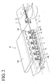
FIG. 2 is a perspective view showing a configuration of bonding/cutting apparatus; -
FIG. 3 is a perspective view of a clamp unit of the bag body transfer apparatus; -
FIG. 4 is a perspective view of the opener; -
FIGs. 5A and 5B show a series of steps for making an opening in the bag body by the opener;FIG. 5A showing the bag body located between the plate members andFIG. 5B showing the bag body interposed between the plate members; -
FIGs. 6A and 6B show steps followingFIGs. 5A and 5B ;FIG. 6A showing a state in which the bag body is withdrawn from the bag body transfer apparatus andFIG. 6B showing a state in which the bag body is moved to the port bonding apparatus; -
FIGs. 7A and 7B show steps followingFIGs. 6A and 6B ;FIG.7A showing a state in which the plate members are pushed widthwise to open the opening andFIG.7B showing a state in which the bag body is brought closer to the port; -
FIG. 8 is a perspective view of a holder unit of the port transfer apparatus; -
FIG. 9 is a perspective view of the port preheater; -
FIGs. 10A and 10B show steps followingFIGs. 7A and 7B ;FIG. 10A showing a state in which the port is inserted into the opening of the bag body andFIG. 10B showing a state in which the opening in which the port is inserted is bonded; and -
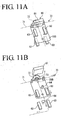
FIGs. 11A and 11B show steps followingFIGs. 10A and 10B ;FIG. 11A showing a state in which the clamping of the bag body by the plate members is released andFIG. 11B showing a state in which the port sealing die is detached from the bag body. - With reference now to the attached drawings, an embodiment of the present invention will be explained in detail below.
-
FIG. 1 illustrates a schematic configuration of resinbag manufacturing equipment 10 according to an embodiment of the present invention. - The resin
bag manufacturing equipment 10 is provided with afilm feeder 20 that feeds a ribbon-shaped film F, a bonding/cutting apparatus (bag body bonding apparatus, cutting apparatus) 30 that bonds three sides of the film F fed from thefilm feeder 20 and cuts the film F along an outside shape of the resin bag, a cooler/remover 40 that cools the bonded part by the bonding/cutting apparatus 30 and removes unnecessary portions from the film F, a bag separator (separation apparatus) 50 that separates the film F at cutting parts intoindividual bag bodies 100, anopener 60 that opens one side not bonded of the separatedbag bodies 100, aport transfer apparatus 70 that supplies aport 200 to anopening 101 of thebag body 100 made by theopener 60, aport bonding apparatus 80 that bonds theport 200 supplied from theport transfer apparatus 70 to theopening 101 of thebag body 100 and a port cooler 90 that cools the bonded part between thebag body 100 and theport 200 in that order. - The
film feeder 20 is provided with a rawfilm material roller 22 that holds a raw film material roll (roll) 21 of a two-ply ribbon-shaped film F, anip roller 23 that unreels the film F from the rawfilm material roll 21, adancer roll 24 that gives/adjusts tension of the unreeled film F and abackward dancer roll 25 for causing the film F to retrocede in the direction opposite to the unreeling direction by making the film F move up and down in the direction orthogonal to the surface of the film F by anair cylinder 25a. - As shown in
FIG. 2 , the bonding/cutting apparatus 30 is provided with a pair of dies 31A and 31B located above and below the film F and a die drive mechanism (not shown) that drives the dies 31A and 31B to move up and down. - The dies 31A and 31B are provided with a
bonding part 32 that bonds three sides of thebag body 100 other than theopening 101 for bonding theport 200 and a cuttingpart 33 that cuts the film F along the outside shape of thebag body 100 on the perimeter side of thebonding part 32. According to the present embodiment, one set of dies 31A and 31B are provided with thebonding parts 32 and cuttingparts 33 corresponding to sixbag bodies 100. - The
bonding part 32 and cuttingpart 33 have a convex shape protruding from the dies 31A and 31B, are heated by a heater and bond and cut two films F respectively when pressed against the films F. Here, the cuttingpart 33 does not completely cut the film F but leaves a portion in the thickness direction thereof uncut. In this way, the mutually neighboringbag bodies - A bag
body transfer apparatus 11 is provided facing the bonding/cutting apparatus 30. The bagbody transfer apparatus 11 has anendless belt 12 provided with a plurality ofclamp units 13 located at predetermined intervals. Eachclamp unit 13 moves along the orbit of thebelt 12 by driving thebelt 12 to circulate using a motor (not shown) or the like. - As shown in
FIG. 3 , theclamp unit 13 is constructed of aflat plate 14 to be inserted into theopening 101 with which theport 200 is bonded in a post-process for thebag body 100 bonded by the bonding/cutting apparatus 30, a pair ofclamp members FIG. 2 for theclamp member 15B) that clamp thebag body 100 so as to sandwich theplate 14 when theplate 14 is inserted into theopening 101 and adrive section 16 that drives theseclamp members - The
clamp members protrusions clamp members bag body 100 is clamped, theseprotrusions bag body 100. At theopening 101 of thebag body 100, convex parts which form convex shapes in mutually facing directions are formed in the two films F by theprotrusions plate 14 is pulled out later and which makes it possible to easily open theopening 101 in a post-process. Furthermore, when theprotrusions bag body 100, thebag body 100 can be reliably clamped and held. - Furthermore, as shown in
FIG. 2 , aguide 18 is provided upstream of the bonding/cutting apparatus 30 to make a gap between the two films F, F of the two-ply film F. Downstream of theguide 18, theplate 14 is inserted into the gap formed between the two films F, F by theguide 18. -
Such clamp units 13 clamp the film F when the bonding/cutting apparatus 30 bonds and cuts three sides of the film F. That is, theclamp units 13 are provided at an interval corresponding to the pitch of sixbag bodies 100 between the dies 31A and 31B. - As shown in
FIG. 1 , such a bagbody transfer apparatus 11 is provided with thebelt 12 along these apparatuses so as to transfer thebag body 100 from the bonding/cutting apparatus 30 to theopener 60. - The cooler/
remover 40 cools thebag body 100 and fixes the bonded part. For cooling of thebag body 100, various appropriate techniques can be adopted such as pressing a plate cooled by a refrigerant such as a liquid against thebag body 100 or spraying a gas such as air. - Furthermore, the cooler/
remover 40 removes unnecessary parts other than thebag body 100 from the film F. Removal of the unnecessary parts can be done by gripping the unnecessary parts of the film F using a chuck member (not shown) or the like and pulling out the unnecessary parts using a cylinder apparatus or the like. The removed film F is ejected at an appropriate location by opening the chuck member. When a hole or the like for hanging a resin bag as a finished product is formed, the hole is formed by the bonding/cutting apparatus 30 in a preceding process simultaneously with the bonding and cutting and the hole is pierced by aneedle 41 at the cooler/remover 40 to remove the portion corresponding to the hole. - The
bag separator 50 separates the plurality ofbag bodies 100 which are connected to each other by portions remaining in the thickness direction into theindividual bag bodies 100. Separation is performed by clamping theindividual bag bodies 100 usingclamping plates 51, pushing upflat separators 52 between the mutually neighboringbag bodies backward dancer roll 25 through theair cylinder 25a in the direction orthogonal to the surface of the film F, causing the film F to retrocede toward the rawfilm material roll 21 and pulling the film F, and thereby cutting the portion in the thickness direction of the film F remaining between the mutually neighboringbag bodies - The
opener 60 holds the separatedbag body 100 and opens theopening 101 which is the non-bonded part of thebag body 100. For this purpose, as shown inFIG. 4 , anupper frame 61A and alower frame 61B are arranged substantially in parallel so as to be located above and below thebag body 100 transferred by the bagbody transfer apparatus 11. Theupper frame 61A andlower frame 61B are moved closer to or away from each other in the vertical direction by anip cylinder 62. - A pair of
plate members suction cup 64 are provided on the under side at an end of theupper frame 61A and the upper side at an end of thelower frame 61B respectively. - The upper and
lower plate members opening 101 of thebag body 100 respectively and the upper andlower plate members bag body 100 from both sides of theopening 101 when thenip cylinder 62 causes theupper frame 61A andlower frame 61B to come closer to each other. - Furthermore, the upper and
lower plate members arms bases air cylinder 66a and alink mechanism 66b causes thearms plate members opening 101 can be opened by rotating thearms plate members opening 101 of thebag body 100 is clamped. - The suction cups 64 are intermediate parts between the pair of
plate members opening 101 of thebag body 100 transferred by the bagbody transfer apparatus 11. The suction cups 64 located above and below are moved up and down by air cylinders (suction cup drive mechanisms) 67 and theopening 101 is opened when the upper andlower suction cups opening 101 of thebag body 100. - Furthermore, the above described
upper frame 61A andlower frame 61B can be moved forward or backward by a travelingcylinder 68 in the direction orthogonal to the direction in which thebag body 100 is transferred by the bagbody transfer apparatus 11. - Six sets of such
upper frames 61A andlower frames 61B are provided in correspondence with the dies 31A and 31B. Theupper frame 61A andlower frame 61B are movable along a guide (not shown) between a position facing the bagbody transfer apparatus 11 and theport bonding apparatus 80. - In the
opener 60, as shown inFIG. 5A , at a position facing the bagbody transfer apparatus 11, theupper frame 61A and thelower frame 61B are first moved forward (direction shown by the arrow in the figure) by the travelingcylinder 68 inFIG. 4 with respect to thebag body 100 held by theclamp unit 13 of the bagbody transfer apparatus 11 and the upper andlower plate members opening 101 above and below. - Next, as shown in
FIG. 5B , thenip cylinder 62 inFIG. 4 causes theupper frame 61A and thelower frame 61B to move closer to each other and the upper andlower plate members bag body 100. After the clamping by the upper andlower plate members bag body 100 by theclamp members clamp unit 13 is released. - As shown in
FIG. 6A , theupper frame 61A and thelower frame 61B are moved backward by the travelingcylinder 68 inFIG. 4 and thebag body 100 held by the upper andlower plate members clamp unit 13 of the bagbody transfer apparatus 11. This causes thebag body 100 to be transferred from theclamp unit 13 to theopener 60. - After this, as shown in
FIG. 6B , thesuction cups 64 are made to suction thebag body 100 through the upper andlower air cylinders 67. As shown inFIG. 1 , theupper frame 61A and thelower frame 61B are moved from the position facing the bagbody transfer apparatus 11 to theport bonding apparatus 80. Simultaneously with this operation, as shown inFIG. 7A , thearms lower plate members lower suction cups 64 are moved away from each other by theair cylinders 67 to open theopening 101. - The
port 200 is supplied from theport transfer apparatus 70 to thebag body 100 held by theopener 60 as described above and transferred to theport bonding apparatus 80 with theopening 101 left open. - Here, the
port transfer apparatus 70 will be explained. - The
port transfer apparatus 70 is provided with a plurality ofholder units 72 on anendless belt 71 at predetermined intervals. Eachholder unit 72 is moved along the orbit of thebelt 71 by driving thebelt 71 to circulate using a motor (not shown) or the like. - As shown in
FIG. 8 , eachholder unit 72 is provided with aport holder 73 having an insertion hole (not shown) through which theport 200 is supplied by a port feeder (not shown). - Furthermore, on both sides of the
port holder 73 are a pair ofclamp members bag body 100 with which theport 200 is bonded and drivesections 75 for driving theclamp members - As shown in
FIG. 1 , with such aholder units 72, theport 200 supplied from the port feeder (not shown) is inserted into theport holder 73. Eachholder unit 72 transfers theport 200 held to a post-process along the orbit of thebelt 71 through the circulation driving of thebelt 71. - The
port 200 transferred by theholder unit 72 is first transferred to aport preheater 76. - As shown in
FIG. 9 , theport preheater 76 is provided with anair heater 77 that jets hot air to preheat theport 200 held by theholder unit 72 and aport rotation mechanism 78 that rotates theport holder 73 holding theport 200. - As for the
port rotation mechanism 78, aplate 78a is provided with agear 78b, amotor 78c that drives thegear 78b to rotate,pulleys belt 78f to transmit the torque of themotor 78c to thegear 78b and thisplate 78a is driven by anair cylinder 78g to move in the vertical direction. - On the other hand, the
holder unit 72 is provided with theaforementioned port holder 73 in a manner pivotable around the axis of theport 200 held and is further provided with agear 79 coaxial with theport holder 73. Thisgear 79 is designed to engage with thegear 78b when theplate 78a of theport rotation mechanism 78 is lowered by theair cylinder 78g. Driving themotor 78c drives theport holder 73 to rotate. - In this way, while the
port rotation mechanism 78 is rotating theport 200 held by theport holder 73, theair heater 77 blows hot air over theport 200 and theport 200 is thereby uniformly preheated. - As shown in
FIG. 1 , sixsuch port preheaters 76 are provided in correspondence with the dies 31A and 31B, and moreover, this embodiment provides two sets of six port preheaters to allow two-stage preheating. - The
port 200 preheated by theport preheater 76 is transferred to theport bonding apparatus 80 while being held by theholder unit 72. - As shown in
FIG. 7A , thebag body 100 held by theopener 60 and with theopening 101 left open, faces theport 200 held by theholder unit 72. - Next, as shown in
FIG. 7B , the suction by the upper andlower suction cups upper frame 61A and thelower frame 61B are moved forward by the travelingcylinder 68 inFIG. 4 . As shown inFIG. 10A , theport 200 held by theholder unit 72 is inserted into theopening 101 of thebag body 100. At this moment, even when the suction by the upper andlower suction cups opening 101 is kept open through widthwise approaching by the upper andlower plate members - Next, the upper and
lower plate members opening 101. In this condition, theopening 101 of thebag body 100 and theport 200 inserted into theopening 101 are bonded by theport bonding apparatus 80. For this purpose, theport bonding apparatus 80 is provided with a pair of upper and lower port sealing dies 81, 81. The port sealing die 81 is provided with a semicircular recessedpart 81a corresponding to the outside shape of theport 200 andflat parts bag body 100. These port sealing dies 81, 81 are heated by a heater (not shown) to within a predetermined temperature range. Furthermore, the port sealing dies 81, 81 are driven to move up and down by an air cylinder (not shown) or the like to move closer to or away from thebag body 100 andport 200. - As shown in
FIG. 10B , in such aport bonding apparatus 80, the upper and lower port sealing dies 81, 81 are moved closer to each other and pressed against thebag body 100 andport 200. The recessedpart 81a then bonds theopening 101 and theport 200 inserted therein and theflat parts opening 101. In this way, theport 200 is bonded to thebag body 100 and a resin bag is formed. At this moment, the three sides of thebag body 100 have already been bonded and when theopening 101 andport 200 are bonded, the film F making up thebag body 100 is hardly wrinkled. - After the bonding is completed, as shown in
FIG. 11A , theupper frame 61A and thelower frame 61B are moved away from each other by thenip cylinder 62 inFIG. 4 and the clamping of thebag body 100 by the upper andlower plate members - After this, the
upper frame 61A and thelower frame 61B return to the positions facing the bagbody transfer apparatus 11. - Next, as shown in
FIG. 11B , the upper and lower port sealing dies 81, 81 are moved away from each other and detached from thebag body 100 andport 200. In this condition, thebag body 100 is bonded to theport 200 and held by theholder unit 72. - After this, the
holder unit 72 is moved by circulation driving of thebelt 71 and the bag body 100 (resin bag) to which theport 200 is bonded is transferred to theport cooler 90. - In the
port cooler 90, the bonded part between theport 200 andbag body 100 is cooled bycooling blocks port 200 andbag body 100 from both sides for cooling. - After this, the resin bag in which the
port 200 and thebag body 100 are bonded is transferred to a filling step which is a post-process, charging of filling stuff from theport 200 into thebag body 100 and capping of theport 200 or the like may be performed. - As described above, after the entire perimeter of the
bag body 100 other than theopening 101 is bonded by the bonding/cutting apparatus 30, theport 200 is inserted into theopening 101, and theopening 101 andport 200 are bonded by theport bonding apparatus 80. This allows the bonding/cutting apparatus 30 to perform two-dimensional bonding and prevents the film F from wrinkling. Furthermore, theport bonding apparatus 80 needs only to perform three-dimensional bonding with theport 200 inserted into theopening 101 of thebag body 100, and moreover, the port sealing die 81 having the recessedpart 81a andflat parts 81b provides a bonding line in the direction substantially orthogonal to the axial line of thetubular port 200, and therefore though the length of the film F in the width direction is shortened by the amount corresponding to the portion wrapped around the entire perimeter of theport 200, both ends of the film F can be brought closer to each other even with three-dimensional bonding and the film F is thereby hardly wrinkled. - In this way, it is possible to prevent the film F from being wrinkled around the bonded part between the
bag body 100 andport 200 which may spoil the appearance, prevent gaps from being produced due to a failure to realize reliable bonding and manufacture a resin bag reliably and with high quality. - Furthermore, it is possible to automatically insert the
port 200 held by theholder unit 72 of theport transfer apparatus 70 into theopening 101 of thebag body 100 with theopening 101 opened by theopener 60 and thereby automate the entire manufacturing process of the resin bag. - In this case, by pressing the
plate members opening 101 and moving theplate members opening 101, suctioning thebag body 100 by thesuction cups 64 in the intermediate part between theplate members plate 14 between the two films F at the stage of bonding and forming thebag body 100 by the bonding/cutting apparatus 30 and forming protrusions on the film F of theopening 101 by theprotrusions 17 provided on theclamp members opening 101 by theopener 60. - Furthermore, by interposing the
plate 14 between the two films F at the stage of bonding and forming thebag body 100 using the bonding/cutting apparatus 30, theplate 14 remains inserted in theopening 101 after bonding. By clamping thebag body 100 using theclamp members bag body 100 can be held as it is. In this way, thebag body 100 can be held and transferred speedily. - In addition, in the
port bonding apparatus 80, theport 200 to be inserted into theopening 101 of thebag body 100 is held by theport holder 73 of theport transfer apparatus 70 and transferred and supplied. After theport 200 is inserted into theopening 101 of thebag body 100 and bonded by theport bonding apparatus 80, it is possible to transfer thebag body 100 with which theport 200 is bonded to a post-process with theport 200 held by theport transfer apparatus 70. - Furthermore, the bonding/
cutting apparatus 30 has thebonding part 32 that bonds the film F to the dies 31A and 31B and the cuttingpart 33 that cuts the film F, and the cuttingpart 33 cuts the film F by leaving part of the film F in the thickness direction instead of completely cutting the film F and keeps the mutually neighboringbag bodies 100 connected to each other. Therefore, the cutting condition by the cuttingpart 33 need not be severely adjusted as in the case where the film F is completely cut and attention is focused on a setting of conditions for bonding by thebonding part 32 and it is thereby possible to reduce time and trouble for adjustment and cost or the like. - The above described embodiment has illustrated the configuration of the components of the resin
bag manufacturing equipment 10, but it is possible to adopt any configurations other than that described above as long as the required functions can be realized within a range not departing from the essence of the present invention. - Furthermore, it is possible to make selections from the configuration described in the above described embodiment or modify the configuration to a different one as appropriate without departing from the essence of the present invention.
Claims (9)
- Resin bag manufacturing equipment for manufacturing a resin bag into which a fluid is charged, comprising:a bag body bonding apparatus that forms an opening at only one side of a pair of films unreeled from a roll and bonds a remaining entire perimeter to form a bag body;a cutting apparatus that cuts the films along an outside shape of the bag body;an opener that opens the opening of the bag body; anda port bonding apparatus that inserts a tubular port into the opening opened by the opener and bonds the opening and the port.
- The resin bag manufacturing equipment according to claim 1, wherein the opener comprises:a pair of plate members that is pressed against both sides of the opening on both surfaces of the bag body; anda widthwise approaching mechanism that moves the plate members on both sides of the opening toward a central portion of the opening while pressing the plate members against the bag body and opens the opening.
- The resin bag manufacturing equipment according to claim 2, wherein the opener comprises:a suction cup that suctions the bag body in a central portion of the pair of plate members; anda suction cup drive mechanism that lifts the suction cup away from a surface of the bag body.
- The resin bag manufacturing equipment according to any one of claims 1 to 3, further comprising a bag body transfer apparatus that transfers the bag body from the bag body bonding apparatus to the opener,
wherein the bag body transfer apparatus comprises a flat plate to be inserted into the opening and a clamp member that clamps the bag body from both surfaces, and
the bag body bonding apparatus performs bonding with the plate inserted between the pair of films. - The resin bag manufacturing equipment according to claim 4, wherein the clamp member clamps the bag body from both sides of the plate inserted into the opening and comprises a protrusion dug into the bag body.
- The resin bag manufacturing equipment according to any one of claims 1 to 5, further comprising a port transfer apparatus that transfers the port to be inserted into the opening of the bag body by the port bonding apparatus,
wherein the port transfer apparatus comprises a port holder in which the tubular port is inserted and held,
the port bonding apparatus inserts the port held by the port holder into the opening of the bag body opened by the opener and performs bonding, and
the port transfer apparatus transfers the bag body where the opening and the port are bonded to a post-process while holding the port. - The resin bag manufacturing equipment according to claim 6, further comprising a port preheater that preheats the port held by the port holder of the port transfer apparatus before transferring the port to the port bonding apparatus.
- The resin bag manufacturing equipment according to claim 7, wherein the port preheater comprises a port rotation mechanism that rotates the port holder holding the port.
- The resin bag manufacturing equipment according to any one of claims 1 to 8, wherein the bag body bonding apparatus and the cutting apparatus share a having a bonding part that bonds the film and a cutting part that cuts the film,
the cutting part cuts the film by leaving a portion of the film in a thickness direction and keeps the mutually neighboring bag bodies connected, and
a separator is further provided in a post-process of the cutting apparatus to separate the mutually neighboring bag bodies which are connected through the portion of the film in the thickness direction.
Applications Claiming Priority (1)
| Application Number | Priority Date | Filing Date | Title |
|---|---|---|---|
| PCT/JP2008/065549 WO2010023753A1 (en) | 2008-08-29 | 2008-08-29 | Resin bag production equipment |
Publications (3)
| Publication Number | Publication Date |
|---|---|
| EP2351642A1 true EP2351642A1 (en) | 2011-08-03 |
| EP2351642A4 EP2351642A4 (en) | 2015-07-15 |
| EP2351642B1 EP2351642B1 (en) | 2018-02-21 |
Family
ID=41720942
Family Applications (1)
| Application Number | Title | Priority Date | Filing Date |
|---|---|---|---|
| EP08809616.9A Active EP2351642B1 (en) | 2008-08-29 | 2008-08-29 | Resin bag production equipment |
Country Status (5)
| Country | Link |
|---|---|
| EP (1) | EP2351642B1 (en) |
| JP (1) | JP5069789B2 (en) |
| CN (1) | CN101808815B (en) |
| TW (1) | TWI354623B (en) |
| WO (1) | WO2010023753A1 (en) |
Families Citing this family (12)
| Publication number | Priority date | Publication date | Assignee | Title |
|---|---|---|---|---|
| CN102858526B (en) | 2010-09-10 | 2015-11-25 | 三菱重工食品包装机械株式会社 | Resin bag production equipment |
| CN103737983B (en) * | 2013-12-28 | 2016-05-18 | 宁波瑞成包装材料有限公司 | Film adds mouth device |
| CN103737978B (en) * | 2013-12-28 | 2016-05-18 | 宁波瑞成包装材料有限公司 | A kind ofly automatically add mouth device for film |
| CN103737985A (en) * | 2013-12-28 | 2014-04-23 | 宁波瑞成包装材料有限公司 | Film automatic nozzle-adding device |
| CN103737979B (en) * | 2013-12-28 | 2016-05-18 | 宁波瑞成包装材料有限公司 | Automatically add mouth device |
| CN103737982A (en) * | 2013-12-28 | 2014-04-23 | 宁波瑞成包装材料有限公司 | Device for automatically forming mouth in lengthwise direction of film |
| CN103737984A (en) * | 2013-12-28 | 2014-04-23 | 宁波瑞成包装材料有限公司 | Longitudinal automatic nozzle adding device for thin film |
| CN103737977A (en) * | 2013-12-28 | 2014-04-23 | 宁波瑞成包装材料有限公司 | Automatic nozzle adding device for film |
| CN106853699A (en) * | 2017-02-28 | 2017-06-16 | 魏成龙 | A kind of packing machine |
| CN108189482B (en) * | 2017-12-29 | 2023-05-16 | 山东新华医疗器械股份有限公司 | A blood bag bag making machine and its rotating tube loading device |
| CN108000947B (en) * | 2017-12-29 | 2023-12-01 | 山东新华医疗器械股份有限公司 | A blood bag making machine and its high frequency welding device |
| CN116175979B (en) * | 2023-02-07 | 2024-05-24 | 常熟市泰宁医疗器材有限责任公司 | Assembling equipment and method for assembling urine bag catheter |
Family Cites Families (10)
| Publication number | Priority date | Publication date | Assignee | Title |
|---|---|---|---|---|
| JPS4117424Y1 (en) * | 1964-10-15 | 1966-08-12 | ||
| JPS57194918A (en) * | 1981-05-23 | 1982-11-30 | Taisei Kikai Kk | Packer |
| US5324233A (en) * | 1992-09-09 | 1994-06-28 | W. R. Grace & Co.-Conn. | Method and apparatus for sealing fitment tubes into pouches |
| JP2001293798A (en) * | 2000-04-13 | 2001-10-23 | Q P Corp | Method and apparatus for inserting and welding a port to a bag mouth |
| JP4726326B2 (en) * | 2001-05-23 | 2011-07-20 | 株式会社フジシールインターナショナル | Manufacturing method of bag-shaped container with a stopper, and bag-shaped container with a stopper |
| JP3942522B2 (en) * | 2002-10-16 | 2007-07-11 | 日立造船株式会社 | Port making device for bag making machine |
| JP4150610B2 (en) * | 2003-02-26 | 2008-09-17 | 東洋自動機株式会社 | Spout insertion sealing device and bag making and packaging machine using the device |
| CN100484742C (en) * | 2004-03-30 | 2009-05-06 | 株式会社细川洋行 | Method and apparatus for producing bag with mouth member |
| JP4673069B2 (en) * | 2004-03-30 | 2011-04-20 | 株式会社細川洋行 | Manufacturing method and manufacturing apparatus for bag with mouth member |
| CN2926044Y (en) * | 2006-06-26 | 2007-07-25 | 山东新华医疗器械股份有限公司 | Impact Non-PVC film automatic bag-making packer |
-
2008
- 2008-08-29 EP EP08809616.9A patent/EP2351642B1/en active Active
- 2008-08-29 CN CN200880109525.1A patent/CN101808815B/en active Active
- 2008-08-29 JP JP2010510578A patent/JP5069789B2/en active Active
- 2008-08-29 WO PCT/JP2008/065549 patent/WO2010023753A1/en not_active Ceased
- 2008-11-12 TW TW097143696A patent/TWI354623B/en active
Non-Patent Citations (1)
| Title |
|---|
| See references of WO2010023753A1 * |
Also Published As
| Publication number | Publication date |
|---|---|
| TW201008767A (en) | 2010-03-01 |
| JPWO2010023753A1 (en) | 2012-01-26 |
| CN101808815A (en) | 2010-08-18 |
| TWI354623B (en) | 2011-12-21 |
| JP5069789B2 (en) | 2012-11-07 |
| CN101808815B (en) | 2012-07-18 |
| WO2010023753A1 (en) | 2010-03-04 |
| EP2351642A4 (en) | 2015-07-15 |
| EP2351642B1 (en) | 2018-02-21 |
Similar Documents
| Publication | Publication Date | Title |
|---|---|---|
| EP2351642B1 (en) | Resin bag production equipment | |
| JP4358642B2 (en) | Flexible packaging | |
| CN107848644A (en) | Packaging machine and related method of operation for packaging individual or groups and/or stacks of products in packages of thermoplastic material obtained from film unwound from reels | |
| CN108025507A (en) | For manufacturing the apparatus and method of polybag | |
| KR20110020799A (en) | Apparatus and method for manufacturing plastic bags | |
| CN106863912B (en) | Packaging bag preparation system and method | |
| JP2009029080A (en) | Polymer film joining method and apparatus | |
| CN113211871B (en) | A fully automatic blood bag making machine | |
| JP2004136904A (en) | Method and apparatus for opening opening of bag-shaped container and port mounting apparatus for bag making machine having opening opening apparatus | |
| CN106113532A (en) | Vacuum heat-insulation plate flanging all-in-one, vacuum heat-preserving board assembly line and production method | |
| JP3845163B2 (en) | Equipment for producing containers with spouts | |
| JPH09262914A (en) | Bag making machine | |
| CN110588069A (en) | Packaging bag forming device and method | |
| KR20170136334A (en) | Produce equipment for pouch | |
| JP5144134B2 (en) | Manufacturing method of adhesive-containing pouch | |
| CN112249432B (en) | Opening device, film sealing and packaging machine and film sealing and packaging method | |
| CN211105944U (en) | Packaging bag forming device | |
| KR102924184B1 (en) | Apparatus for manufacturing infusion container | |
| EP2948377B1 (en) | Form, fill and seal packaging machine | |
| EP2614954B1 (en) | Resin bag production equipment | |
| CN222522976U (en) | A large mesh bag packaging machine | |
| JP6329098B2 (en) | Bag filling and packaging method and apparatus using double bags | |
| JP4607653B2 (en) | Spout mounting device | |
| ES2982606T3 (en) | Production process of an elongated tubular bag, machine and elongated tubular bag | |
| JP3316036B2 (en) | Film fusing and sealing equipment |
Legal Events
| Date | Code | Title | Description |
|---|---|---|---|
| PUAI | Public reference made under article 153(3) epc to a published international application that has entered the european phase |
Free format text: ORIGINAL CODE: 0009012 |
|
| 17P | Request for examination filed |
Effective date: 20100322 |
|
| AK | Designated contracting states |
Kind code of ref document: A1 Designated state(s): AT BE BG CH CY CZ DE DK EE ES FI FR GB GR HR HU IE IS IT LI LT LU LV MC MT NL NO PL PT RO SE SI SK TR |
|
| DAX | Request for extension of the european patent (deleted) | ||
| RA4 | Supplementary search report drawn up and despatched (corrected) |
Effective date: 20150612 |
|
| RIC1 | Information provided on ipc code assigned before grant |
Ipc: B29C 65/00 20060101ALN20150608BHEP Ipc: B29C 35/04 20060101ALN20150608BHEP Ipc: B31B 1/84 20060101AFI20150608BHEP Ipc: B31B 23/74 20060101ALI20150608BHEP |
|
| STAA | Information on the status of an ep patent application or granted ep patent |
Free format text: STATUS: EXAMINATION IS IN PROGRESS |
|
| 17Q | First examination report despatched |
Effective date: 20161124 |
|
| RAP1 | Party data changed (applicant data changed or rights of an application transferred) |
Owner name: MITSUBISHI HEAVY INDUSTRIES MECHATRONICS SYSTEMS, |
|
| REG | Reference to a national code |
Ref country code: DE Ref legal event code: R079 Ref document number: 602008054118 Country of ref document: DE Free format text: PREVIOUS MAIN CLASS: B31B0001840000 Ipc: B31B0070840000 |
|
| GRAP | Despatch of communication of intention to grant a patent |
Free format text: ORIGINAL CODE: EPIDOSNIGR1 |
|
| STAA | Information on the status of an ep patent application or granted ep patent |
Free format text: STATUS: GRANT OF PATENT IS INTENDED |
|
| RIC1 | Information provided on ipc code assigned before grant |
Ipc: B31B 155/00 20170101ALN20170925BHEP Ipc: B29C 65/74 20060101ALN20170925BHEP Ipc: B29C 35/04 20060101ALN20170925BHEP Ipc: B31B 70/04 20170101ALN20170925BHEP Ipc: B29C 65/78 20060101ALN20170925BHEP Ipc: B31B 160/10 20170101ALN20170925BHEP Ipc: B31B 70/84 20170101AFI20170925BHEP Ipc: B29C 65/18 20060101ALN20170925BHEP |
|
| INTG | Intention to grant announced |
Effective date: 20171018 |
|
| GRAS | Grant fee paid |
Free format text: ORIGINAL CODE: EPIDOSNIGR3 |
|
| RAP1 | Party data changed (applicant data changed or rights of an application transferred) |
Owner name: MITSUBISHI HEAVY INDUSTRIES MACHINERY SYSTEMS, LTD |
|
| GRAA | (expected) grant |
Free format text: ORIGINAL CODE: 0009210 |
|
| STAA | Information on the status of an ep patent application or granted ep patent |
Free format text: STATUS: THE PATENT HAS BEEN GRANTED |
|
| AK | Designated contracting states |
Kind code of ref document: B1 Designated state(s): AT BE BG CH CY CZ DE DK EE ES FI FR GB GR HR HU IE IS IT LI LT LU LV MC MT NL NO PL PT RO SE SI SK TR |
|
| REG | Reference to a national code |
Ref country code: GB Ref legal event code: FG4D |
|
| REG | Reference to a national code |
Ref country code: CH Ref legal event code: EP |
|
| REG | Reference to a national code |
Ref country code: DE Ref legal event code: R096 Ref document number: 602008054118 Country of ref document: DE Ref country code: AT Ref legal event code: REF Ref document number: 971248 Country of ref document: AT Kind code of ref document: T Effective date: 20180315 |
|
| REG | Reference to a national code |
Ref country code: IE Ref legal event code: FG4D |
|
| REG | Reference to a national code |
Ref country code: NL Ref legal event code: MP Effective date: 20180221 |
|
| REG | Reference to a national code |
Ref country code: LT Ref legal event code: MG4D |
|
| REG | Reference to a national code |
Ref country code: AT Ref legal event code: MK05 Ref document number: 971248 Country of ref document: AT Kind code of ref document: T Effective date: 20180221 |
|
| PG25 | Lapsed in a contracting state [announced via postgrant information from national office to epo] |
Ref country code: HR Free format text: LAPSE BECAUSE OF FAILURE TO SUBMIT A TRANSLATION OF THE DESCRIPTION OR TO PAY THE FEE WITHIN THE PRESCRIBED TIME-LIMIT Effective date: 20180221 Ref country code: CY Free format text: LAPSE BECAUSE OF FAILURE TO SUBMIT A TRANSLATION OF THE DESCRIPTION OR TO PAY THE FEE WITHIN THE PRESCRIBED TIME-LIMIT Effective date: 20180221 Ref country code: NO Free format text: LAPSE BECAUSE OF FAILURE TO SUBMIT A TRANSLATION OF THE DESCRIPTION OR TO PAY THE FEE WITHIN THE PRESCRIBED TIME-LIMIT Effective date: 20180521 Ref country code: FI Free format text: LAPSE BECAUSE OF FAILURE TO SUBMIT A TRANSLATION OF THE DESCRIPTION OR TO PAY THE FEE WITHIN THE PRESCRIBED TIME-LIMIT Effective date: 20180221 Ref country code: ES Free format text: LAPSE BECAUSE OF FAILURE TO SUBMIT A TRANSLATION OF THE DESCRIPTION OR TO PAY THE FEE WITHIN THE PRESCRIBED TIME-LIMIT Effective date: 20180221 Ref country code: NL Free format text: LAPSE BECAUSE OF FAILURE TO SUBMIT A TRANSLATION OF THE DESCRIPTION OR TO PAY THE FEE WITHIN THE PRESCRIBED TIME-LIMIT Effective date: 20180221 Ref country code: LT Free format text: LAPSE BECAUSE OF FAILURE TO SUBMIT A TRANSLATION OF THE DESCRIPTION OR TO PAY THE FEE WITHIN THE PRESCRIBED TIME-LIMIT Effective date: 20180221 |
|
| PG25 | Lapsed in a contracting state [announced via postgrant information from national office to epo] |
Ref country code: AT Free format text: LAPSE BECAUSE OF FAILURE TO SUBMIT A TRANSLATION OF THE DESCRIPTION OR TO PAY THE FEE WITHIN THE PRESCRIBED TIME-LIMIT Effective date: 20180221 Ref country code: LV Free format text: LAPSE BECAUSE OF FAILURE TO SUBMIT A TRANSLATION OF THE DESCRIPTION OR TO PAY THE FEE WITHIN THE PRESCRIBED TIME-LIMIT Effective date: 20180221 Ref country code: SE Free format text: LAPSE BECAUSE OF FAILURE TO SUBMIT A TRANSLATION OF THE DESCRIPTION OR TO PAY THE FEE WITHIN THE PRESCRIBED TIME-LIMIT Effective date: 20180221 Ref country code: BG Free format text: LAPSE BECAUSE OF FAILURE TO SUBMIT A TRANSLATION OF THE DESCRIPTION OR TO PAY THE FEE WITHIN THE PRESCRIBED TIME-LIMIT Effective date: 20180521 Ref country code: GR Free format text: LAPSE BECAUSE OF FAILURE TO SUBMIT A TRANSLATION OF THE DESCRIPTION OR TO PAY THE FEE WITHIN THE PRESCRIBED TIME-LIMIT Effective date: 20180522 |
|
| PG25 | Lapsed in a contracting state [announced via postgrant information from national office to epo] |
Ref country code: IT Free format text: LAPSE BECAUSE OF FAILURE TO SUBMIT A TRANSLATION OF THE DESCRIPTION OR TO PAY THE FEE WITHIN THE PRESCRIBED TIME-LIMIT Effective date: 20180221 Ref country code: RO Free format text: LAPSE BECAUSE OF FAILURE TO SUBMIT A TRANSLATION OF THE DESCRIPTION OR TO PAY THE FEE WITHIN THE PRESCRIBED TIME-LIMIT Effective date: 20180221 Ref country code: EE Free format text: LAPSE BECAUSE OF FAILURE TO SUBMIT A TRANSLATION OF THE DESCRIPTION OR TO PAY THE FEE WITHIN THE PRESCRIBED TIME-LIMIT Effective date: 20180221 Ref country code: PL Free format text: LAPSE BECAUSE OF FAILURE TO SUBMIT A TRANSLATION OF THE DESCRIPTION OR TO PAY THE FEE WITHIN THE PRESCRIBED TIME-LIMIT Effective date: 20180221 |
|
| REG | Reference to a national code |
Ref country code: DE Ref legal event code: R097 Ref document number: 602008054118 Country of ref document: DE |
|
| PG25 | Lapsed in a contracting state [announced via postgrant information from national office to epo] |
Ref country code: SK Free format text: LAPSE BECAUSE OF FAILURE TO SUBMIT A TRANSLATION OF THE DESCRIPTION OR TO PAY THE FEE WITHIN THE PRESCRIBED TIME-LIMIT Effective date: 20180221 Ref country code: DK Free format text: LAPSE BECAUSE OF FAILURE TO SUBMIT A TRANSLATION OF THE DESCRIPTION OR TO PAY THE FEE WITHIN THE PRESCRIBED TIME-LIMIT Effective date: 20180221 Ref country code: CZ Free format text: LAPSE BECAUSE OF FAILURE TO SUBMIT A TRANSLATION OF THE DESCRIPTION OR TO PAY THE FEE WITHIN THE PRESCRIBED TIME-LIMIT Effective date: 20180221 |
|
| REG | Reference to a national code |
Ref country code: CH Ref legal event code: PK Free format text: BERICHTIGUNGEN |
|
| PLBE | No opposition filed within time limit |
Free format text: ORIGINAL CODE: 0009261 |
|
| STAA | Information on the status of an ep patent application or granted ep patent |
Free format text: STATUS: NO OPPOSITION FILED WITHIN TIME LIMIT |
|
| RIC2 | Information provided on ipc code assigned after grant |
Ipc: B31B 70/04 20170101ALN20170925BHEP Ipc: B29C 65/74 20060101ALN20170925BHEP Ipc: B29C 65/78 20060101ALN20170925BHEP Ipc: B31B 160/10 20170101ALN20170925BHEP Ipc: B29C 65/18 20060101ALN20170925BHEP Ipc: B31B 155/00 20170101ALN20170925BHEP Ipc: B31B 70/84 20170101AFI20170925BHEP Ipc: B29C 35/04 20060101ALN20170925BHEP |
|
| 26N | No opposition filed |
Effective date: 20181122 |
|
| REG | Reference to a national code |
Ref country code: CH Ref legal event code: PK Free format text: BERICHTIGUNGEN |
|
| RIC2 | Information provided on ipc code assigned after grant |
Ipc: B31B 70/84 20170101AFI20170925BHEP Ipc: B31B 70/04 20170101ALN20170925BHEP Ipc: B29C 35/04 20060101ALN20170925BHEP Ipc: B29C 65/18 20060101ALN20170925BHEP Ipc: B31B 155/00 20170101ALN20170925BHEP Ipc: B29C 65/78 20060101ALN20170925BHEP Ipc: B31B 160/10 20170101ALN20170925BHEP Ipc: B29C 65/74 20060101ALN20170925BHEP |
|
| PG25 | Lapsed in a contracting state [announced via postgrant information from national office to epo] |
Ref country code: SI Free format text: LAPSE BECAUSE OF FAILURE TO SUBMIT A TRANSLATION OF THE DESCRIPTION OR TO PAY THE FEE WITHIN THE PRESCRIBED TIME-LIMIT Effective date: 20180221 |
|
| PG25 | Lapsed in a contracting state [announced via postgrant information from national office to epo] |
Ref country code: MC Free format text: LAPSE BECAUSE OF FAILURE TO SUBMIT A TRANSLATION OF THE DESCRIPTION OR TO PAY THE FEE WITHIN THE PRESCRIBED TIME-LIMIT Effective date: 20180221 |
|
| REG | Reference to a national code |
Ref country code: CH Ref legal event code: PL |
|
| GBPC | Gb: european patent ceased through non-payment of renewal fee |
Effective date: 20180829 |
|
| PG25 | Lapsed in a contracting state [announced via postgrant information from national office to epo] |
Ref country code: CH Free format text: LAPSE BECAUSE OF NON-PAYMENT OF DUE FEES Effective date: 20180831 Ref country code: LI Free format text: LAPSE BECAUSE OF NON-PAYMENT OF DUE FEES Effective date: 20180831 Ref country code: LU Free format text: LAPSE BECAUSE OF NON-PAYMENT OF DUE FEES Effective date: 20180829 |
|
| REG | Reference to a national code |
Ref country code: BE Ref legal event code: MM Effective date: 20180831 |
|
| PG25 | Lapsed in a contracting state [announced via postgrant information from national office to epo] |
Ref country code: BE Free format text: LAPSE BECAUSE OF NON-PAYMENT OF DUE FEES Effective date: 20180831 Ref country code: FR Free format text: LAPSE BECAUSE OF NON-PAYMENT OF DUE FEES Effective date: 20180831 |
|
| PG25 | Lapsed in a contracting state [announced via postgrant information from national office to epo] |
Ref country code: GB Free format text: LAPSE BECAUSE OF NON-PAYMENT OF DUE FEES Effective date: 20180829 |
|
| PG25 | Lapsed in a contracting state [announced via postgrant information from national office to epo] |
Ref country code: MT Free format text: LAPSE BECAUSE OF NON-PAYMENT OF DUE FEES Effective date: 20180829 |
|
| PG25 | Lapsed in a contracting state [announced via postgrant information from national office to epo] |
Ref country code: TR Free format text: LAPSE BECAUSE OF FAILURE TO SUBMIT A TRANSLATION OF THE DESCRIPTION OR TO PAY THE FEE WITHIN THE PRESCRIBED TIME-LIMIT Effective date: 20180221 |
|
| PG25 | Lapsed in a contracting state [announced via postgrant information from national office to epo] |
Ref country code: HU Free format text: LAPSE BECAUSE OF FAILURE TO SUBMIT A TRANSLATION OF THE DESCRIPTION OR TO PAY THE FEE WITHIN THE PRESCRIBED TIME-LIMIT; INVALID AB INITIO Effective date: 20080829 Ref country code: PT Free format text: LAPSE BECAUSE OF FAILURE TO SUBMIT A TRANSLATION OF THE DESCRIPTION OR TO PAY THE FEE WITHIN THE PRESCRIBED TIME-LIMIT Effective date: 20180221 |
|
| PG25 | Lapsed in a contracting state [announced via postgrant information from national office to epo] |
Ref country code: IE Free format text: LAPSE BECAUSE OF NON-PAYMENT OF DUE FEES Effective date: 20180829 |
|
| PG25 | Lapsed in a contracting state [announced via postgrant information from national office to epo] |
Ref country code: IS Free format text: LAPSE BECAUSE OF FAILURE TO SUBMIT A TRANSLATION OF THE DESCRIPTION OR TO PAY THE FEE WITHIN THE PRESCRIBED TIME-LIMIT Effective date: 20180621 |
|
| PLBE | No opposition filed within time limit |
Free format text: ORIGINAL CODE: 0009261 |
|
| REG | Reference to a national code |
Ref country code: CH Ref legal event code: PK Free format text: BERICHTIGUNGEN |
|
| 17Q | First examination report despatched |
Effective date: 20161124 |
|
| 26N | No opposition filed |
Effective date: 20181122 |
|
| DAX | Request for extension of the european patent (deleted) | ||
| INTG | Intention to grant announced |
Effective date: 20171018 |
|
| RA4 | Supplementary search report drawn up and despatched (corrected) |
Effective date: 20150612 |
|
| RAP2 | Party data changed (patent owner data changed or rights of a patent transferred) |
Owner name: MITSUBISHI HEAVY INDUSTRIES MACHINERY SYSTEMS, LTD. |
|
| RIC2 | Information provided on ipc code assigned after grant |
Ipc: B29C 65/78 20060101ALN20170925BHEP Ipc: B29C 65/74 20060101ALN20170925BHEP Ipc: B29C 65/18 20060101ALN20170925BHEP Ipc: B29C 35/04 20060101ALN20170925BHEP Ipc: B31B 160/10 20170101ALN20170925BHEP Ipc: B31B 155/00 20170101ALN20170925BHEP Ipc: B31B 70/04 20170101ALN20170925BHEP Ipc: B31B 70/84 20170101AFI20170925BHEP |
|
| PGFP | Annual fee paid to national office [announced via postgrant information from national office to epo] |
Ref country code: DE Payment date: 20250702 Year of fee payment: 18 |