EP2948377B1 - Form, fill and seal packaging machine - Google Patents
Form, fill and seal packaging machine Download PDFInfo
- Publication number
- EP2948377B1 EP2948377B1 EP14743366.8A EP14743366A EP2948377B1 EP 2948377 B1 EP2948377 B1 EP 2948377B1 EP 14743366 A EP14743366 A EP 14743366A EP 2948377 B1 EP2948377 B1 EP 2948377B1
- Authority
- EP
- European Patent Office
- Prior art keywords
- inner bag
- forming film
- seal
- sealing
- outer bag
- Prior art date
- Legal status (The legal status is an assumption and is not a legal conclusion. Google has not performed a legal analysis and makes no representation as to the accuracy of the status listed.)
- Not-in-force
Links
Images


Classifications
-
- B—PERFORMING OPERATIONS; TRANSPORTING
- B65—CONVEYING; PACKING; STORING; HANDLING THIN OR FILAMENTARY MATERIAL
- B65B—MACHINES, APPARATUS OR DEVICES FOR, OR METHODS OF, PACKAGING ARTICLES OR MATERIALS; UNPACKING
- B65B41/00—Supplying or feeding container-forming sheets or wrapping material
- B65B41/12—Feeding webs from rolls
-
- B—PERFORMING OPERATIONS; TRANSPORTING
- B65—CONVEYING; PACKING; STORING; HANDLING THIN OR FILAMENTARY MATERIAL
- B65B—MACHINES, APPARATUS OR DEVICES FOR, OR METHODS OF, PACKAGING ARTICLES OR MATERIALS; UNPACKING
- B65B61/00—Auxiliary devices, not otherwise provided for, for operating on sheets, blanks, webs, binding material, containers or packages
- B65B61/28—Auxiliary devices, not otherwise provided for, for operating on sheets, blanks, webs, binding material, containers or packages for discharging completed packages from machines
-
- B—PERFORMING OPERATIONS; TRANSPORTING
- B65—CONVEYING; PACKING; STORING; HANDLING THIN OR FILAMENTARY MATERIAL
- B65B—MACHINES, APPARATUS OR DEVICES FOR, OR METHODS OF, PACKAGING ARTICLES OR MATERIALS; UNPACKING
- B65B9/00—Enclosing successive articles, or quantities of material, e.g. liquids or semiliquids, in flat, folded, or tubular webs of flexible sheet material; Subdividing filled flexible tubes to form packages
- B65B9/10—Enclosing successive articles, or quantities of material, in preformed tubular webs, or in webs formed into tubes around filling nozzles, e.g. extruded tubular webs
- B65B9/20—Enclosing successive articles, or quantities of material, in preformed tubular webs, or in webs formed into tubes around filling nozzles, e.g. extruded tubular webs the webs being formed into tubes in situ around the filling nozzles
-
- B—PERFORMING OPERATIONS; TRANSPORTING
- B65—CONVEYING; PACKING; STORING; HANDLING THIN OR FILAMENTARY MATERIAL
- B65B—MACHINES, APPARATUS OR DEVICES FOR, OR METHODS OF, PACKAGING ARTICLES OR MATERIALS; UNPACKING
- B65B2220/00—Specific aspects of the packaging operation
- B65B2220/16—Packaging contents into primary and secondary packaging
- B65B2220/20—Packaging contents into primary and secondary packaging the primary packaging being bags, the secondary packaging being further bags, the primary bags being either finished or formed concurrently with the secondary bags
Description
- There is described a form, fill and seal packaging machine that is capable of forming, filling and sealing one or more inner bags within an outer bag.
- United States Patent
8,015,783 (Iwasa et al ) entitled "Form-Fill-Seal Machine" is an example of a form-fill-seal packaging machine.
Document DE 10 2008 029285 A1 teaches for packaging non liquid foodstuffs or semi-luxury goods, a packaging having a protective packaging containing an inner packaging which contains the material to be packaged. The two packagings are each produced from a strip, each strip being guided together to form a flexible tube. The outer packaging means is perforated and glued at one end to the inner packaging such that, when the outer packaging is torn open, the inner packaging, rather than being destroyed, remains attached to the one part of the torn-open protective packaging. The inner packaging preferably consists of a different material compared to the outer packaging means. - There is provided a form, fill and seal packaging machine which includes a bagging chamber and a fill chamber disposed vertically above the bagging chamber. The fill chamber has a bottom closure that opens to facilitate movement of filled bags from the fill chamber to the bagging chamber. An outer bag forming assembly is provided which includes at least one outer bag forming film support for supporting a flexible sealable film for forming an outer bag and guide rollers to guide movement of sheets of the outer bag forming film. Feed rollers are used to advance the sheets of the outer bag forming film. Outer bag lengthwise edge sealing jaws are provided having opposed sealing surfaces which are movable from a rest position spaced from the sheets of the outer bag forming film to a sealing position where the sealing surfaces are brought together to compress and seal together lengthwise edges of the sheets of the outer bag forming film. Outer bag transverse sealing and cutting jaws are positioned transverse to the outer bag forming film. The outer bag transverse sealing and cutting jaws have opposed sealing and cutting surfaces which are movable from a rest position spaced from the outer bag forming film to a sealing position where the sealing and cutting surfaces are brought together to compress, seal and cut the sheets of the outer bag forming film to create an outer bag that is fed into the bagging chamber. An inner bag forming assembly is provided which includes at least one inner bag forming film support for supporting a flexible sealable film for forming an inner bag and guide rollers for guiding movement of sheets of the inner bag forming film. A feed nozzle is provided for supplying product located in a space between the sheets of the inner bag forming film. Feed rollers engage and advance the inner bag forming film in a downward direction over the feed nozzle in a controlled manner to a pre-set length into the fill chamber. Inner bag lengthwise edge sealing jaws are provided that have opposed sealing surfaces which are movable from a rest position spaced from the sheets of the inner bag forming film to a sealing position where the sealing surfaces are brought together to compress and seal the sheets of the inner bag forming film. Inner bag transverse sealing and cutting jaw are positioned transverse to the inner bag forming film. The inner bag transverse sealing and cutting jaws have opposed sealing and cutting surfaces which are movable from a rest position spaced from the sheets of the inner bag forming film to a sealing position where the sealing and cutting surfaces are brought together to compress, seal and cut the sheets of the inner bag forming film forming a transverse seal. An upper side of the transverse seal defines a bottom seal for the inner bag forming film entering the fill chamber and a lower side of the transverse seal defines a top seal for a filled inner bag exiting the fill chamber. The nozzle supplies a measured amount of fill product into the inner bag. An actuator opens the bottom closure of the fill chamber, resulting in the filled inner bag being lowered out of the fill chamber into the outer bag positioned in the bagging chamber. The outer bag sealing and cutting jaws serve to compress, seal and cut the sheets of the outer bag forming film forming a transverse seal. An upper side of the transverse seal serves as a bottom seal for the outer bag entering the bagging chamber and a lower side of the transverse seal serves as a top seal for a sealed outer bag containing one or more of the filled inner bags exiting the bagging chamber.
- These and other features will become more apparent from the following description in which reference is made to the appended drawings, the drawings are for the purpose of illustration only and are not intended to be in any way limiting, wherein:
-
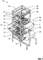
FIG. 1 is a perspective view of a form fill and seal packaging machine. -
FIG. 2 is a perspective view of a mid-frame assembly of the form fill and seal packaging machine illustrated inFIG. 1 , with top frame section and lower support frame section removed. -
FIG. 3 is an exploded perspective view of the mid-frame assembly illustrated inFIG. 2 . -
FIG. 4 is a perspective view of lengthwise sealing jaws. -
FIG. 5 is a perspective view of a finger hole cutting assembly associated with the lengthwise sealing jaws illustrated inFIG. 4 . -
FIG. 6 is a perspective view of transverse sealing jaws used to seal inner bag. -
FIG. 7 is a side elevation view, in section, of the transverse sealing jaws illustrated inFIG. 6 . -
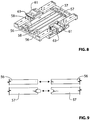
FIG. 8 is a perspective view of transverse sealing jaws used to seal outer bag. -
FIG. 9 is a side elevation view, in section, of the transverse sealing jaws illustrated inFIG. 8 . -
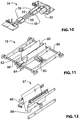
FIG. 10 is a perspective view of a feed roller assembly. -
FIG. 11 is a perspective view of a bottom closure with inner bag support. -
FIG. 12 is a perspective view of a drop control plate assembly. -
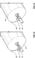
FIG. 13 is a detailed side elevation view showing roll support detail for outer bag film material. -
FIG. 14 is a detailed side elevation view showing roll support detail for inner bag film material. -
FIG. 15 is a perspective view showing feed nozzle positioning in relation to sheets of an inner bag forming film. -
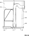
FIG. 16 is a front elevation view showing feed nozzle and inner film support detail. -
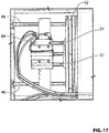
FIG. 17 is a detailed side elevation view of the actuator for the lengthwise sealing jaws illustrated inFIG. 4 . -
FIG. 18 is a side elevation view of a tensioning and release mechanism for the pinch rollers of the feed roller assembly illustrated inFIG. 10 . -
FIG. 19 is a perspective view of optical sensor positioning for feeding inner bag forming film. -
FIG. 20 is a detailed side elevation view of actuator for the lower gripper of the transverse sealing assembly ofFIG. 7 . -
FIG. 21 is a side elevation view of a lower end of a bottom closure for upper fill chamber and guide rollers for outer bag forming film. -
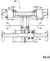
FIG. 22 is side elevation view of the lower end of the bottom closure illustrated inFIG. 21 , with positioning of lengthwise sealing jaws shown. -
FIG. 23 is a perspective view of a bank of flavour system pumps. - A form, fill, and seal packaging machine, generally identified by
reference numeral 10, will now be described with reference toFIG. 1 through 23 . - Referring to
FIG. 1 ,packaging machine 10 has astructural frame 12 which defines alower bagging chamber 14 and anupper fill chamber 16.Fill chamber 16 is referred to as an "upper" chamber and it is disposed vertically abovebagging chamber 14.Fill chamber 16 has a bottom closure, generally identified byreference numeral 18.Bottom closure 18 is not clearly visible inFIG 1 , and will hereafter be further described with reference toFIG 3 . - An outer bag forming assembly is provided, which is generally identified by
reference numeral 20. As will hereinafter be further described, outerbag forming assembly 20 forms an outer bag which is fed intobagging chamber 14. An inner bag forming assembly is provided, which is generally identified byreference numeral 50. As will hereinafter be further described, innerbag forming assembly 50 forms an inner bag which is fed intofill chamber 16. - Referring to
FIG. 3 , the primary components ofpackaging machine 10 are shown in an exploded view with separate modules. It should be noted that some of these modules are common to both outerbag forming assembly 20 and innerbag forming assembly 50, and will be identified as such. - Referring to
FIG. 3 , outerbag forming assembly 20 includes at least one outer bag formingfilm support 22 for supporting aroll 24 of flexible sealable outerbag forming film 26 for forming an outer bag. Two outer bag forming film supports 22 have been illustrated. There will follow an explanation with respect to innerbag forming assembly 50, as to how a single bag forming filing support could be used in place of the two outer bag forming film supports 22 illustrated. Referring toFIG. 13 ,support 22 and arotatable shaft 23 forroller 24 of outerbag forming film 26 is shown. - Referring to
FIG. 3 , guiderollers 28 are provided. Referring toFIG. 21 , guiderollers 28 guide movement and provide a change of direction forsheets bag forming film 26. As will hereinafter be further described, guiderollers 28, as illustrated inFIG. 3 , are similarly used for innerbag forming assembly 50. - Referring to
FIG. 3 , a feed roller assembly, generally identified byreference numeral 34 is provided to advance outerbag forming film 26. As will hereinafter be further described, feedroller assembly 34, as illustrated inFIG. 3 , is similarly used for innerbag forming assembly 50. Referring toFIG 10 , feed roller assembly includes a support frame 36, two rotatably mountedpinch rollers 38 mounted onshafts 39 and anelectric drive motor 40 which serves to rotate at least one and preferably both ofrollers 38. Referring toFIG. 18 , a tensioning andrelease mechanism 41 is provided to movepinch rollers 38 apart for the purpose of threading bag forming film betweenpinch rollers 38 and then movingpinch rollers 38 into proper engagement with the bag forming film. Tensioning andrelease mechanism 41 includes a pivotinghandle 43 which is attached to ashaft 45. Movement ofhandle 43 in one direction moves one ofpinch rollers 38 away from the other ofpinch rollers 38 and movement ofhandle 43 in the other direction moves the onepinch roller 38 toward the other ofpinch rollers 38. Ascrew clamp 47 is provided for clamping themovable pinch roller 38 in the selected position. - Referring to
FIG. 3 , a pair of lengthwiseedge sealing jaws 42 are provided. As will hereinafter be further described, lengthwiseedge sealing jaws 42, as illustrated inFIG. 3 , are similarly used for innerbag forming assembly 50. Referring toFIG. 4 , lengthwiseedge sealing jaws 42 have opposed sealing surfaces 44. Sealingjaws 42 are movable along tracks in the form of support bars 46 from a spaced apart rest position, spaced fromsheets bag forming film 26 to a sealing position where sealing surfaces 44 are brought together to compress and seal together lengthwise edges ofsheets bag forming film 26 to form an outer tubular structure. Referring toFIG. 17 ,air cylinder actuator 49 is illustrated and the stroke provided byshafts 51 to move lengthwise one ofedge sealing jaws 42. - Referring to
FIG. 5 , one of sealingjaws 42 has a projecting C shapedmale portion 33 with interacts with a mating C shapedfemale portion 35 on the other of sealingjaws 42. As broad sealingband 37 is sealed along one lengthwise edge, a handle in taking the form of C shapedfinger holes 39 are formed. Thebroad sealing band 37 will eventually become the "top" of the bag, as the orientation when passing through the machine is not the same as the orientation of the bag during use. The orientation of C shaped finger holes 39 is of importance. The rounded portion should bear the weight of the bag, as a reverse orientation leaves potential tear points. - Referring to
FIG. 3 , transverse sealing and cuttingjaws 56 are provided. Referring toFIG. 8 , transverse sealing and cuttingjaws 56 are positioned transverse to the tubular structure which exits lengthwiseedge sealing jaws 42. Transverse sealing and cuttingjaws 56 have opposed sealing and cuttingsurfaces 58 which are movable from a rest position spaced from the tubular structure to a sealing position where sealing and cuttingsurfaces 58 are brought together to compress, seal and cut the tubular structure ofsheets bag forming film 26 to create an outer bag that is fed into baggingchamber 14. Referring toFIG. 9 , in addition to sealing and cuttingjaws 56, there is providedlower grippers 57.Lower grippers 57 grip outerbag forming film 26, while sealing and cuttingjaws 56 are activated. Movement of transverse cuttingjaws 56 andlower grippers 57 is effected through the use ofair cylinder actuators 61 that moveshafts 63 back and forth that are attached to eitherlower rippers 57 or sealing and cuttingjaws 56. - Referring to
FIG. 3 , innerbag forming assembly 50 includes a single inner bag formingfilm support 60 for supporting aroll 62 of flexible scalable innerbag forming film 64 for forming an inner bag. The reason only asingle roll 62 is required is that innerbag forming film 64 is fed folded in a lengthwise direction to create twosheets bag forming film 64 open and requiring lengthwise sealing. Referring toFIG. 14 ,support 60 andshaft 65 about which roll 62 of innerbag forming film 64 rotates is shown. - Referring to
FIG. 1 , guiderollers 28, as described above, guide movement and provide a change of direction tosheets bag forming film 64 being drawn fromroll 62 supported by inner bag formingfilm support 60. - Referring to
FIG. 3 , afeednozzle 70 is provided for supplying product to the inner bag.Feed nozzle 70 has anoutlet 72 formed as a thin rectangular tube, aconduit 74 which allowsoutlet 72 to be positioned, aflow control valve 76 to control flow and aninner film support 78. - Referring to
FIG. 1 , afeed rollers assembly 34, as described above with reference toFIG. 10 , is used to engage and advance innerbag forming film 64 in a downward direction overfeed nozzle 70 in a controlled manner to a pre-set length intofill chamber 16. Lengthwiseedge sealing jaws 42, as described above, are used to compress and sealsheets bag forming film 64 to form an inner tubular structure. It is to be noted that instead of a pair of lengthwiseedge sealing jaws 42, a single set of lengthwiseedge sealing jaws 42 can be used as innerbag forming film 64 is folded in a length wise direction leaving only one lengthwise edge of innerbag forming film 64 open and requiring lengthwise sealing. - As will hereinafter be further described in relation to operation with reference to
FIG. 15 andFIG. 16 ,feed nozzle 70 extends down between is positioned in aspacebetween sheets bag forming film 64. - Referring to
FIG. 3 , innerbag forming assembly 50 has transverse sealing and cuttingjaws 48 that differ from transverse sealing and cuttingjaws 56 used with outerbag forming assembly 20. Referring toFIG. 6 and FIG. 7 , transverse sealing and cuttingjaws 48 are movable along tracks in the form of support bars 54 from a spaced apart position to a position in which opposed sealing and cuttingsurfaces 52 are brought together to compress, seal and cut the tubular structure ofsheets bag forming film 64 to create an inner bag that is fed into fillingchamber 14. Transverse sealing and cuttingjaws 48, as described above, are positioned transverse to innerbag forming film 64 and the resulting inner tubular structure. Sealing and cuttingsurfaces 52 are brought together to compress, seal and cutsheets bag forming film 64 forming a transverse seal. It is to be noted that an upper side of the transverse seal defines a bottom seal for innerbag forming film 64 enteringfill chamber 16 and a lower side of the transverse seal defines a top seal for a filled inner bag exitingfill chamber 16. Referring toFIG. 7 , in addition to sealing and cuttingjaws 48, there is providedupper grippers 71 andlower grippers 73.Upper grippers 71 andlower grippers 73 grip innerbag forming film 64, while sealing and cuttingjaws 48 are activated. As with transverse cutting and sealingjaws 56, cutting and sealingjaws 48 use anair cylinder actuator 61 which extends and retractsshafts 63. However, separate pairs ofair cylinders 75 are used to extendupper grippers 71 andlower grippers 73. - Referring to
FIG. 3 , the inner bag, formed as described, rests infill chamber 16 upon abottom closure 18. Referring toFIG. 11 ,bottom closure 18 forms aninner bag support 80 having twomovable portions Movable portions Bottom closure 18 opens to provide access fromfill chamber 16 to baggingchamber 14.Feed nozzle 70 is used to supply a measured amount of fill product into the inner bag. Anair cylinder actuator 85 is then used to openbottom closure 18 offill chamber 16, this causemovable portions chamber 14. - Depending upon the nature of the product, it is not always desirable to have the inner bag freely by force of gravity. Referring to
FIG. 3 , adrop control assembly 87 is provide. Referring toFIG. 12 ,drop control assembly 87 consists of pivotally mounteddrop control plates 88. By controlling the pivotal movement ofdrop control plates 88, a rate at the inner bag drops fromfill chamber 16 into outer bag in baggingchamber 14 can be controlled. There are various ways of controlling movement ofdrop control plates 88, the preferred way being through the use of fluid filled cylinders. In the proto-types, the movement ofdrop control plates 88 was controlled by air cylinders. - Referring to
FIG. 3 andFIG. 8 , once the inner bag has dropped fromfill chamber 16 into the outer bag in baggingchamber 14, transverse sealing and cuttingjaws 56, as described above, serve to compress, seal and cutsheets bag forming film 26 forming a transverse seal. It is to be noted that an upper side of the transverse seal being a bottom seal for the outer bag entering bagging chamber 14and a lower side of the transverse seal being a top seal for a sealed outer bag containing one or more of the filled inner bags exitingbagging chamber 14. Referring toFIG. 3 , a pivoting outer bag support andbottom closure 90 for baggingchamber 14 is provided which pivots to allow removal of the outer bag. Should dropping by force of gravity be undesirable, adrop control assembly 87 may be used, as described above. - Referring to
FIG. 19 , anoptical sensor 94, known as an "eye mark" sensor is provided which detects the passage of a mark placed on the bag films. The PLC initiates and stops rotation ofpinch rollers 38 offeed roller assembly 34, based upon the number of "marks" that have passed, as determined byoptical sensor 94. The number of marks will be determined by the size of inner bag that is to be produced. - Referring to
FIG. 1 , the duel process form-fill-seal packaging machine system disclosed herein, uses asingle roll 62 of folded scalable film and tworolls 24 of unfolded or flat stock sealable film with dispensing fitment attachment to produce a single package with an outer bag with a carry handle, comprising of a sealed inner bag filled with liquid, semi liquid or dry goods, sealed inside an outer bag shell with an integrated mobility handle. The operation of the apparatus components is controlled by a programmable logic controller (PLC) (not shown).Packaging machine 10 can produce one bag filled with product. At the same time making the outer bag in which the filled bag will be placed inside the outer carrying bag. There will be between 2 and 60 inner bags deposited into the outer bag. With the touch screen you can make mutable bags and place them in the outer carrying bag. Also you can have a different combination of flavours. - Referring to
FIG. 1 , roll 62 of folded innerbag forming film 64, such as a plastic film can be of different thickness depending on what strength is needed to support the weight of the product being packaged.Roll 62 is mounted on the outside of packingmachine 10 and along its height. Referring toFIG. 14 ,roll 62 is mounted onsupport brackets 60 and arotatable support shaft 65 securing the roll of folded innerbag forming film 64 in place. Referring toFIG. 1 , the roll of folded material passes over a mechanical station at which is controlled by the PLC. At which time the fitment is placed a ND sealed in place. Referring toFIG. 1 andFIG. 15 , folded innerbag forming film 64 fromroll 62 is moved along on a series ofguide rollers 28 which guide and alter the direction of folded innerbag forming film 64. Referring toFIG. 10 , folded innerbag forming film 64 is drawn fromroller 62 byfeed roller assembly 34 includespinch rollers 38 driven bymotor 40. Movement ofpinch rollers 38 onrotatable shaft 39 promotes alignment of open side of folded innerbag forming film 64 with the sealing equipment of packagingmachine 10. Referring toFIG. 1 andFIG. 15 , afirst guide roller 28 turns folded innerbag forming film 64 horizontally across the top of packagingmachine 10 and asecond guide roller 28, which is mounted at the very top of packagingmachine 10, turns folded innerbag forming film 64 vertically to be advanced in a downward direction. Referring toFIG. 1 andFIG. 20 , a furtherfeed roller assembly 34 i s provide to draw folded innerbag forming film 64 downwardly ontoinner bag support 80.
The draw time is controlled by the PLC to the length needed for the size of bag needed. Referring toFIG. 19 , the positioning innerbag forming film 64 is detected byoptical sensor 94, which operates as an "eye mark" sensor sensing marks placed upon innerbag forming film 64 at set intervals. - Referring to
FIG. 15 and16 , feedroller assembly 34 pulls folded innerbag forming film 64 along a path so that a fixed verticallyinner film support 78 andoutlet 72 offeed nozzle 70 extends into a space betweensheets bag forming film 64. Folded innerbag forming film 64 fully envelopsfilm support 78 andoutlet 72 ofnozzle 70.Outlet 72 ofnozzle 70 is vertically oriented and is made from two sheets bent to form a rectangular tube. When placed betweensheets bag forming film 64,outlet 72 andfilm support 78 help guide folded innerbag forming film 64, while the inner bag is being formed, sealed and filled. Referring toFIG. 15 , folded inner bag forming film advances between upper conventional vertical pneumatic sealing equipment that includes sealingjaws 42. Referring toFIG. 20 , feed roller assembly 34 (best illustrated inFIG. 10 ) is controlled by the PLC. Which will turn feedmotor 40 on and off for a preset time. This will determined the width of the bag to be made. When the folded film is positioned ininner bag support 80, advancement of the film stops when the desired width of film has advanced. - Referring to
FIG. 6 , transverse sealing and cuttingjaws 48, as described above, are positioned transverse to innerbag forming film 64. Sealing and cuttingsurfaces 52 are brought together to compress, seal and cut innerbag forming film 64 to form a transverse seal. As already noted, an upper side of the transverse seal defines a bottom seal for innerbag forming film 64 enteringfill chamber 16 and a lower side of the transverse seal defines a top seal for a filled inner bag exitingfill chamber 16. This means that innerbag forming film 64 advancing toinner bag support 80 already has a bottom seal. This will be appreciated by a review ofFIG. 20 , which shows the relative positioning ofinner bag support 80 relative to transverse sealing and cuttingjaws 48. It should be noted that withair cylinder actuator 61 pulls rather than pushes transverse sealing and cuttingjaws 48 into position. - Referring to
FIG. 4 andFIG. 15 , sealingjaws 42 are brought together to compress the film and seal the open vertical side of the folded innerbag forming film 64 advanced there between with heated sealing bans or wires. The sealing surfaces 44 of sealingjaws 42 are brought together to compress the film and seal the open side of folded innerbag forming film 64 with electrically heated wires or strips. The seal is close to the edge of the material. It should be noted that when sealingjaws 42 are closed, the filling cycle starts at the same time. The inner bag is filled with product such as liquids, semi liquid or dry goods to the desired level when supported withininner bag support 80. Referring toFIG. 23 , a flavour system, generally identified byreference numeral 100 consisting of a bank ofpumps 102 dispensing individual flavours is provided. A time set in the PLC located in the control panel, using a conventional PLC (logic Program Controller) controls the desired level.
Having aseparate pump 102 for each flavour enables packagingmachine 10 to change from flavour to flavour. The open topped bag in innerbag support dispenser 80 is filled from above down a tunnel formed byside sealing jaws 42. The inner bag is filled byfeed nozzle 70. Theoutlet 72 ofnozzle 70 is supplied by asupply conduit 74 controlled bysupply valve 76. The fill material, such as liquid, is passed down throughconduit 74 ofnozzle 70 tooutlet 72 and into the inner bag. The length ofconduit 74 andoutlet 72 will determine a bags width, which will enable the making of different size bags. Various sizes ofnozzle 70 can be made for different sizes of inner bag. Referring toFIG. 11 , the interior shape ofinner bag support 80 is shaped to support the open topped inner bag during filling. Sealingjaws 42 can be water cooled or air cooled which aid in the cooling down process of the plastic seal, will speed up the opening ofjaws 42 sooner enabling faster production cycles. When the fill cycle stops the drip cycle starts and the pre-heat starts for the inner cross cut and sealjaws 48. Referring toFIG. 6 , side sealing is followed in sequence by the fill cycle and upper horizontal pneumatic cross seal and cutjaws 48 which move to compress the film to form a transverse seal widthwise across with heated strip. An electrically heated wire associated the heated strip cuts horizontally widthwise the sealed portion of the film across. Thus, the upper part of the seal forms a bottom seal for the next semi-formed bag film abovejaws 48.
At the same time the seal portion at the lower part the transverse seal forms top seal of the bag which has just been filled and rests oninner bag support 80. Whenjaws 48 open, thereafter,movable portions inner bag support 80 move to a spaced apart position which opens the bottom ofbottom closure 18. Withbottom closure 18 opened, the filled inner bag is dropped and thenbottom closure 18 is closed. It is preferable the sloped bottom ofinner bag support 80 have a slippery surface to overcome inertia and initiate movement of the filled inner bag by force of gravity as soon asmovable portions - Referring to
FIG. 12 , when it is desirable to control the drop rate of the inner bag,drop plates 88 are used. The filled and completely sealed inner bag drops down through spaced apart dropcontrol plates 88 hinged from above and forming a channel slowing the descent of the filled inner bag. An oil control valve inside the control valve hydraulically controls the speed at which dropcontrol plates 88 are able to open. Spring control valves then close dropcontrol plates 88 to form a "V" tunnel wider at the upper entrance waiting for the inner next bag. The filled inner bag drops until it stops at the bottom ofouter bag support 90. The outer bag material is held in place with aid of the outerside seal jaws 42. The inner bag production cycle is then repeated until a desired number of inner bags have been produced and deposited into the outer bag. - Before the filled inner bag can drop down in to an outer bag, the outer bag will have already been made and waiting for it. In order for this process to happen, there is a sequence occurring between the inner bagging and outer bagging process, as per the sequence keyed into the PLC at the control panel. With the PLC every sequence of the machine can be controlled and monitored.
- Referring to
FIG. 1 andFIG. 2 , the outer bagging of the filled inner bag is accomplished by using two rolls ofouter bag film 24 which are located on each side of the machine facing each other so when drawn inward they form each side of the outer bag. Referring toFIG. 13 , the tworolls 24 are each supported byshafts 23 which rotate onsupports 22. Referring toFIG. 21 andFIG. 22 , the outerbag forming film 26 from the tworolls 24 are pulled along overguide rollers 28 that turn the path of the outerbag forming film 26 to vertical to be advanced downwardly. As described above, with reference toFIG. 10 ,pinch rollers 38 offeed roller assembly 34 engage outerbag forming film 26 to advance it, withpinch rollers 38 being driven by means ofmotor 40. Referring toFIG. 4 , lengthwise sealingjaws 42 compress outerbag forming film 26 forming a side seal at each of the open edges. Sealingjaws 42 stay closed immediately after sealing the outer bag side seals to prevent the seals from pulling apart from the weight of the incoming filled inner bag and to hold the outer bag material properly in place as the inner bag, full of product, passes frominner bag support 80 into baggingchamber 14. Referring toFIG. 5 , mounted to sealingjaws 42 are grippingjaws 104. Grippingjaws 104 grip, but they do not seal. They are machined with matching groves that inner lock to hold the outer bag material in place. The configuration resembles that illustrated inFIG. 9 . Referring toFIG. 5 , also mounted to sealing jaw 42 (along what will eventually become the top of the outer bag) the knife described above, with C shapedmale portion 33 mating with C shapedfemale portion 35 to cut a handle in the form of C shaped finger holes 39. This is done at the same time the side seals are done. - Referring to
FIG. 8 , transverse seal and cutjaws 56 form the bottom seal on the outer bag by compressing the material and cutting the film during the initial production set up. Referring toFIG. 9 ,grippers 57 hold the bag material in place to enable activation of transverse seal and cutjaws 56. Once the bottom and the sides of the outer bag have been sealed, the outer bag is pulled down byfeed roller assembly 34 until it reaches the bottom ofouter bag support 90, which has bottom that opens. At this stage the semi formed outer bag is ready to have the filled inner bag deposited inside of it. As described above, as the inner bags are formed and filled they pass from fillingchamber 16 to baggingchamber 14 by force of gravity wheninner bag support 80 ofbottom closure 18 opens. Once a desired number of inner bags (between 2 and 60) are positioned in theouter bag support 90, transverse seal and cutjaws 56 compresses the outer bag film to cut and seal the outer bag forming a seal, to complete the outer bag form, fill, seal, double bagging process. Once the transverse seal and cutjaws 56 close and open, the lengthwise sealingjaws 42 open and remain open until material is drawn down for the next outer bag formation. The process is repeated. - Referring to
FIG. 19 , outer bag film width is controlled by a timer in the PLC to the feed motor or by marks printed on the material which is picked up by the means ofoptical sensor 94 that stops the feed motor this also locates the location of the printed material on the outer bag. - All sealing jaws and opening and closing of jaws are controlled by the PLC. The PLC is set up with a program in such a manner that allows this function to happen in a controlled manner. All sealing jaws can be opened and closed by air cylinders or electric motors.
- All operations to start up with new rolls of material are done with the PLC and in manual position on the control screen. After all the necessary manual operations are done you switch over to the auto cycle. This cycle continues to make bags after each bag cycle is complete. In the PLC and on the screen there is a counter that can be pre-set to make the amount of bag required by pre-setting the number needed.
- Flowing is the sequence in which the bagging machine will operate in the auto mode.
-
Numbers 1, 2, 3, etc. are cycles. A, B, C etc. are functions happening at the same time - 1
- A---side seal
- B---fill
- 2
- A---drip
- B---pre heat lower seal and cut jaws
- 3
- A---close cross seal and cut
- 4
- A---open cross seal and cut jaw
- B---open upper dumper
- c---start material feed motor
- d---close upper dumper
-
Note 1,2,3,4, are all done on the inner bag. When inner bag drops in to outer bag. The inner bag cycle starts again at the same time the outer bag cycle starts as follows - 5
- A---close cross seal and cut jaws
- 6
- A---open cross seal and cut jaws
- B---open lower side seal jaws
- C---open lower dumper
- D---pre heat outer side seals
- E---start outer material feed motor
- 7
- A---close lower outer dumper
- B---close outer side seal and seal
- This machine allows for the forming, filling and sealing of bags containing different volumes of liquid, semi liquid or solids. The system and cycle of this machine allows making a bag inside a bag all in one machine.
- The duel action of the
feed nozzle 70 aids the bag material to be guided though the first stage of making and filling the bag. The high speed production machine is lightweight with a very small footprint and easily transportable. -
Inner bag support 80 supports the bag filled with product so as when transverse sealing and cutjaws 48 close and heated the weight of the fill bag dose not pull the hot soft material from jaws. This same comment is true with respect toouter bag support 90 and transvers sealing and cutjaws 56. There is a cool down cycle in the PLC that allows cooling down time before the jaws open allowing the heated material to bond together creating a seal. - The small footprint reduces the floor space required for a bagging operation, thus reducing overheads.
- It has been found that it is best not to attempt what may be termed the horizontal or transverse seal with the plastic film material under tension. For this reason, grippers support the bag to reduce tension on the plastic film material during the sealing process.
- A series of safety measures have been built into the machine. A safety switch is positioned in the vicinity of the access doors, so that the sealing jaws will not operate when the access doors are open. The sealing jaws close under low pressure and then switch to high pressure only when sensors indicate that they are in contact. Until the sensor is tripped indicating that the jaws are closed, the jaws do not switch to high pressure and the heat does not come on to heat the sealing jaws.
- The side seal assemblies have solid grippers. It is undesirable to have the increasing weight of the inner bag during the filling process rip the inner bag free of the grippers. There must be no movement of the inner bag, until it is time to drop the inner bag into the outer bag.
- Referring to
FIG. 23 , when flavoured liquids are being dispensed, a different pump is provided for each liquid. This enables an outer bag to be filled with up to 60 small bags, while the small bags are filled with a variety of flavours. - The illustrated embodiments have been set forth only as examples and should not be taken as limiting a purposive interpretation of the claims.
Claims (7)
- A form, fill and seal packaging machine (10) for producing a single package with an outer bag with a carry handle, comprising a sealed inner bag filled with liquid, semi liquid or dry goods, sealed inside an outer bag shell with an integrated mobility handle comprising:a bagging chamber (14);a fill chamber (16) disposed vertically above the bagging chamber (14);an outer bag forming assembly (20) comprising:an inner bag forming assembly (50) comprising:at least one outer bag forming film support (22) for supporting a flexible sealable film for forming an outer bag;guide rollers (28) to guide movement of sheets (30, 32) of the outer bag forming film (26);feed rollers (34) that advance the sheets (30, 32) of the outer bag forming film (26);outer bag transverse sealing and cutting jaws (56) positioned transverse to the outer bag forming film (26) and resulting outer tubular structure, the outer bag transverse sealing and cutting jaws (56) having opposed sealing and cutting surfaces (58) which are movable from a rest position spaced from the tubular structure to a sealing position where the sealing and cutting surfaces are brought together to compress, seal and cut the sheets (30, 32) of the outer bag forming film (26) to create an outer bag that is fed into the bagging chamber (14);at least one inner bag forming film support (60) for supporting a flexible sealable film for forming an inner bag;guide rollers (28) for guiding movement of sheets (66, 68) of the inner bag forming film (64);a feed nozzle (70) for supplying product located in a space between the sheets 66 and 68 of the inner bag forming film (64);feed rollers (34) that engage and advance the inner bag forming film (64) in a downward direction over the feed nozzle (70) in a controlled manner to a pre-set length into the
fill chamber (16);inner bag lengthwise edge sealing jaws (42) having opposed sealing surfaces (44) which are movable from a rest position spaced from the sheets (66, 68) of the inner bag forming film (64) to a sealing position where the sealing surfaces (44) are brought together to compress and seal the sheets (66, 68) of the inner bag forming film 64 to form an inner tubular structure;inner bag transverse sealing and cutting jaw (48) positioned transverse to the inner bag forming film (64) and resulting inner tubular structure, the inner bag transverse sealing and cutting jaws (48) having opposed sealing and cutting surfaces (52) which are movable from a rest position spaced from the sheets (66, 68) of the inner bag forming film (64) to a sealing position where the sealing and cutting surfaces are brought together to compress, seal and cut the sheets (66, 68) of the inner bag forming film (64) forming a transverse seal, an upper side of the transverse seal defining a bottom seal for the inner bag forming film (64) entering the fill chamber (16) and a lower side of the transverse seal defining a top seal for a filled inner bag exiting the fill chamber (16);the nozzle supplying a measured amount of fill product into the inner bag;the outer bag sealing and cutting jaws (56) serving to compress, seal and cut the sheets (30, 32) of the outer bag forming film (26) forming a transverse seal, an upper side of the transverse seal being a bottom seal for the outer bag entering the bagging chamber (14) and a lower side of the transverse seal being a top seal for a sealed outer bag containing one or more of the filled inner bags exiting the bagging chamber (14),characterized in thatthe fill chamber (16) has a bottom closure (18) that forms an inner bag support (80) and opens to provide access from the fill chamber (16) to the bagging chamber (14),an actuator for opening the bottom closure (18)of the fill chamber (16) and lowering the filled inner bag out of the fill chamber (16) into the outer bag is positioned in the bagging chamber (14);
outer bag lengthwise edge sealing jaws (42) have opposed sealing surfaces (44) which are movable from a rest position spaced from the sheets (30, 32) of the outer bag forming film (26) to a sealing position where the sealing surfaces (44) are brought together to compress and seal together lengthwise edges of the sheets (30, 32) to the outer bag forming film (26) to form an outer tubular structure;
wherein the inner bag forming film (64) is fed folded in a lengthwise direction leaving only one lengthwise edge of the inner bag forming film (64) open, the inner tubular structure having a heat sealed lengthwise edge of the folded inner bag forming film (64). - The form, fill and seal packaging machine (10) of claim 1, wherein the bottom closure (18) of the fill chamber (16) is comprised of pivotally mounted drop control plates (88), the drop control plates (88) being controlled in their pivot movement, thereby controlling a rate at which the inner bag drops from the fill chamber (16) into the outer bag in the bagging chamber (14).
- The form, fill and seal packaging machine (10) of claim 2, wherein movement of the drop control plates (88) is controlled by air cylinders.
- The form, fill and seal packaging machine (10) of claim 1, wherein the nozzles comprises
a thin rectangle tube which, when placed between the sheets (66, 68) of the inner bag forming film (64), helps guide the inner bag forming film (64). - The form, fill and seal packaging machine (10) of claim 1, wherein a pneumatic outer bag handle jaw cuts and heat seals a handle imprint into the outer bag at the time the horizontal top seal is being formed on the outer bag.
- A method of making an integrated sealed dual bag with an outer bag enclosing a sealed inner bag filled with liquid, semi liquid or dry goods, sealed inside an outer bag shell with an integrated mobility handle of a form fill seal packing machine according to any of claims 1 - 5 comprising:providing a fill chamber (16) vertically disposed above a bagging chamber (14), the fill chamber (16) having a bottom that opens to provide access from the fill chamber (16) to the bagging chamber (14);advancing an outer bag forming film (26) comprising flexible sealable film for forming an outer bag;heat sealing the outer bag forming film (26) lengthwise to form an outer tubular structure;heat sealing the outer tubular structure widthwise to form a bottom seal completing formation of the outer bag;advancing the outer bag into the lower bagging chamber (14);advancing an inner bag forming film (64) comprising a flexible sealable film for forming an inner bag, wherein the inner bag forming film (64) is fed folded in a lengthwise direction leaving only one lengthwise edge of the inner bag forming film (64) open; heat sealing the inner bag forming film (64) lengthwise to form an inner tubular structure; heat sealing the inner tubular structure to form a bottom seal completing formation of the inner bag;advancing the inner bag into the fill chamber (16);filling the inner bag in the fill chamber (16);heat sealing a top of the inner bag in the fill chamber (16);opening the bottom of the fill chamber (16) to release the filled and completely sealed inner bag to drop by force of gravity into the outer bag positioned in the bagging chamber (14); andheat sealing a top of the outer bag with the filled inner bag.
- The method of claim 6, including a step of slowing the drop of the filled inner bag from the fill chamber (16) to the bagging chamber (14) by having it fall through a channel formed by drop control plates (88) pivotally mounted in spaced relation, the drop control plates (88) being controlled in their pivot movement.
Applications Claiming Priority (2)
| Application Number | Priority Date | Filing Date | Title |
|---|---|---|---|
| US201361755650P | 2013-01-23 | 2013-01-23 | |
| PCT/CA2014/000036 WO2014113870A1 (en) | 2013-01-23 | 2014-01-17 | Form, fill and seal packaging machine |
Publications (3)
| Publication Number | Publication Date |
|---|---|
| EP2948377A1 EP2948377A1 (en) | 2015-12-02 |
| EP2948377A4 EP2948377A4 (en) | 2016-11-02 |
| EP2948377B1 true EP2948377B1 (en) | 2018-05-23 |
Family
ID=51226775
Family Applications (1)
| Application Number | Title | Priority Date | Filing Date |
|---|---|---|---|
| EP14743366.8A Not-in-force EP2948377B1 (en) | 2013-01-23 | 2014-01-17 | Form, fill and seal packaging machine |
Country Status (3)
| Country | Link |
|---|---|
| EP (1) | EP2948377B1 (en) |
| CA (1) | CA2898318C (en) |
| WO (1) | WO2014113870A1 (en) |
Families Citing this family (1)
| Publication number | Priority date | Publication date | Assignee | Title |
|---|---|---|---|---|
| CN114194533A (en) * | 2021-12-28 | 2022-03-18 | 江苏热风环保科技有限公司 | Far infrared preheating vacuum packaging method |
Family Cites Families (10)
| Publication number | Priority date | Publication date | Assignee | Title |
|---|---|---|---|---|
| FR2110713A5 (en) * | 1970-10-21 | 1972-06-02 | Thimonnier & Cie | |
| US6623821B1 (en) * | 1995-03-31 | 2003-09-23 | E. I. Du Pont De Nemours And Company | Heat-shrinkable, heat-sealable polyester film for packaging |
| US5716471A (en) * | 1995-10-30 | 1998-02-10 | Elopak Systems Ag | Method for securing articles to laminates |
| EP0836997A1 (en) * | 1996-09-17 | 1998-04-22 | Kraft Foods, Inc. | Apparatus and method for formation of sealed packages |
| US6490846B2 (en) * | 2000-04-21 | 2002-12-10 | Robert G. Koppe | Opening arrangement for zipper-type pouches for continuous motion pouching machinery |
| CA2430200A1 (en) * | 2003-05-28 | 2004-11-28 | Glopak Inc. | High speed bagging system and method |
| US20060150581A1 (en) * | 2005-01-11 | 2006-07-13 | Assembly & Test Worldwide, Llc | Apparatus for manufacturing biodegradable food service article and method |
| US8015783B2 (en) | 2006-10-30 | 2011-09-13 | Ishida Co., Ltd. | Form-fill-seal machine |
| DE102008029285A1 (en) | 2008-06-11 | 2009-12-17 | Optima Filling And Packaging Machines Gmbh | Packaging for food |
| GB2475720A (en) * | 2009-11-27 | 2011-06-01 | Ashwell Packaging Supplies Ltd | Inner pack suspended within pressurized outer pack |
-
2014
- 2014-01-17 EP EP14743366.8A patent/EP2948377B1/en not_active Not-in-force
- 2014-01-17 CA CA2898318A patent/CA2898318C/en active Active
- 2014-01-17 WO PCT/CA2014/000036 patent/WO2014113870A1/en active Application Filing
Non-Patent Citations (1)
| Title |
|---|
| None * |
Also Published As
| Publication number | Publication date |
|---|---|
| EP2948377A1 (en) | 2015-12-02 |
| EP2948377A4 (en) | 2016-11-02 |
| WO2014113870A1 (en) | 2014-07-31 |
| CA2898318C (en) | 2019-02-05 |
| CA2898318A1 (en) | 2014-07-31 |
Similar Documents
| Publication | Publication Date | Title |
|---|---|---|
| EP3319878B1 (en) | Wrapping machine for single or grouped and/or stacked products, in packs of thermoplastic material obtained from film unwound from a reel and related operating method | |
| US6272815B1 (en) | Servo-controlled pouch making apparatus | |
| US6247293B1 (en) | Modular packaging machine with web tension control | |
| US8181433B2 (en) | Method of lap sealing a molten cheese product with non-wax film | |
| US6395317B1 (en) | Process and apparatus for forming dual compartment pouches from a continuous web | |
| EP0023817A1 (en) | Form-fill-seal apparatus and method of making reclosable bags | |
| US4676051A (en) | Method and apparatus for forming, filling and sealing bags made from a continuous plastic sheet | |
| US5112632A (en) | Method and apparatus for forming and hermetically sealing slices of food items | |
| JPH06298210A (en) | Device to form parallelepiped packing container charged with liquid from tubular packing material web | |
| US4779400A (en) | Method and apparatus for forming, filling and sealing bags made from continuous plastic sheets | |
| US6890290B2 (en) | Method and apparatus for producing valve bags | |
| US3597895A (en) | Packaging method and machine | |
| US9505189B2 (en) | Apparatus for forming a plurality of flexible pouches from a continuous web of film | |
| US6047528A (en) | Method and apparatus for continuously forming sealed pouches while linked together | |
| AU2018241892B2 (en) | Bag web and method and equipment for packing items | |
| EP2948377B1 (en) | Form, fill and seal packaging machine | |
| US20160122061A1 (en) | Pouch forming machine with vertical jaw adjustment mechanism | |
| WO2010100751A1 (en) | Individual packing machine | |
| WO2015181242A1 (en) | Machine for filling thermoplastic bags | |
| KR20170136334A (en) | Produce equipment for pouch | |
| US3221474A (en) | Automatic packaging machine | |
| US3071907A (en) | Method and apparatus for the production of tetrahedron-shaped packages | |
| CN114531867B (en) | Improved sealing device | |
| WO2022091155A1 (en) | Cutting unit for making single-dose packages | |
| CN115871998A (en) | System bag packaging all-in-one |
Legal Events
| Date | Code | Title | Description |
|---|---|---|---|
| PUAI | Public reference made under article 153(3) epc to a published international application that has entered the european phase |
Free format text: ORIGINAL CODE: 0009012 |
|
| 17P | Request for examination filed |
Effective date: 20150820 |
|
| AK | Designated contracting states |
Kind code of ref document: A1 Designated state(s): AL AT BE BG CH CY CZ DE DK EE ES FI FR GB GR HR HU IE IS IT LI LT LU LV MC MK MT NL NO PL PT RO RS SE SI SK SM TR |
|
| AX | Request for extension of the european patent |
Extension state: BA ME |
|
| DAX | Request for extension of the european patent (deleted) | ||
| A4 | Supplementary search report drawn up and despatched |
Effective date: 20160930 |
|
| RIC1 | Information provided on ipc code assigned before grant |
Ipc: B65B 9/20 20120101AFI20160926BHEP Ipc: B65B 9/10 20060101ALI20160926BHEP Ipc: B65B 51/30 20060101ALI20160926BHEP Ipc: B65B 41/12 20060101ALI20160926BHEP Ipc: B65B 61/28 20060101ALI20160926BHEP |
|
| STAA | Information on the status of an ep patent application or granted ep patent |
Free format text: STATUS: EXAMINATION IS IN PROGRESS |
|
| 17Q | First examination report despatched |
Effective date: 20170420 |
|
| GRAP | Despatch of communication of intention to grant a patent |
Free format text: ORIGINAL CODE: EPIDOSNIGR1 |
|
| STAA | Information on the status of an ep patent application or granted ep patent |
Free format text: STATUS: GRANT OF PATENT IS INTENDED |
|
| INTG | Intention to grant announced |
Effective date: 20171213 |
|
| GRAS | Grant fee paid |
Free format text: ORIGINAL CODE: EPIDOSNIGR3 |
|
| GRAA | (expected) grant |
Free format text: ORIGINAL CODE: 0009210 |
|
| STAA | Information on the status of an ep patent application or granted ep patent |
Free format text: STATUS: THE PATENT HAS BEEN GRANTED |
|
| AK | Designated contracting states |
Kind code of ref document: B1 Designated state(s): AL AT BE BG CH CY CZ DE DK EE ES FI FR GB GR HR HU IE IS IT LI LT LU LV MC MK MT NL NO PL PT RO RS SE SI SK SM TR |
|
| REG | Reference to a national code |
Ref country code: GB Ref legal event code: FG4D |
|
| REG | Reference to a national code |
Ref country code: CH Ref legal event code: EP |
|
| REG | Reference to a national code |
Ref country code: IE Ref legal event code: FG4D |
|
| REG | Reference to a national code |
Ref country code: AT Ref legal event code: REF Ref document number: 1001335 Country of ref document: AT Kind code of ref document: T Effective date: 20180615 |
|
| REG | Reference to a national code |
Ref country code: DE Ref legal event code: R096 Ref document number: 602014025865 Country of ref document: DE |
|
| REG | Reference to a national code |
Ref country code: NL Ref legal event code: MP Effective date: 20180523 |
|
| REG | Reference to a national code |
Ref country code: LT Ref legal event code: MG4D |
|
| PG25 | Lapsed in a contracting state [announced via postgrant information from national office to epo] |
Ref country code: ES Free format text: LAPSE BECAUSE OF FAILURE TO SUBMIT A TRANSLATION OF THE DESCRIPTION OR TO PAY THE FEE WITHIN THE PRESCRIBED TIME-LIMIT Effective date: 20180523 Ref country code: SE Free format text: LAPSE BECAUSE OF FAILURE TO SUBMIT A TRANSLATION OF THE DESCRIPTION OR TO PAY THE FEE WITHIN THE PRESCRIBED TIME-LIMIT Effective date: 20180523 Ref country code: NO Free format text: LAPSE BECAUSE OF FAILURE TO SUBMIT A TRANSLATION OF THE DESCRIPTION OR TO PAY THE FEE WITHIN THE PRESCRIBED TIME-LIMIT Effective date: 20180823 Ref country code: LT Free format text: LAPSE BECAUSE OF FAILURE TO SUBMIT A TRANSLATION OF THE DESCRIPTION OR TO PAY THE FEE WITHIN THE PRESCRIBED TIME-LIMIT Effective date: 20180523 Ref country code: FI Free format text: LAPSE BECAUSE OF FAILURE TO SUBMIT A TRANSLATION OF THE DESCRIPTION OR TO PAY THE FEE WITHIN THE PRESCRIBED TIME-LIMIT Effective date: 20180523 Ref country code: BG Free format text: LAPSE BECAUSE OF FAILURE TO SUBMIT A TRANSLATION OF THE DESCRIPTION OR TO PAY THE FEE WITHIN THE PRESCRIBED TIME-LIMIT Effective date: 20180823 |
|
| PG25 | Lapsed in a contracting state [announced via postgrant information from national office to epo] |
Ref country code: RS Free format text: LAPSE BECAUSE OF FAILURE TO SUBMIT A TRANSLATION OF THE DESCRIPTION OR TO PAY THE FEE WITHIN THE PRESCRIBED TIME-LIMIT Effective date: 20180523 Ref country code: NL Free format text: LAPSE BECAUSE OF FAILURE TO SUBMIT A TRANSLATION OF THE DESCRIPTION OR TO PAY THE FEE WITHIN THE PRESCRIBED TIME-LIMIT Effective date: 20180523 Ref country code: LV Free format text: LAPSE BECAUSE OF FAILURE TO SUBMIT A TRANSLATION OF THE DESCRIPTION OR TO PAY THE FEE WITHIN THE PRESCRIBED TIME-LIMIT Effective date: 20180523 Ref country code: HR Free format text: LAPSE BECAUSE OF FAILURE TO SUBMIT A TRANSLATION OF THE DESCRIPTION OR TO PAY THE FEE WITHIN THE PRESCRIBED TIME-LIMIT Effective date: 20180523 Ref country code: GR Free format text: LAPSE BECAUSE OF FAILURE TO SUBMIT A TRANSLATION OF THE DESCRIPTION OR TO PAY THE FEE WITHIN THE PRESCRIBED TIME-LIMIT Effective date: 20180824 |
|
| REG | Reference to a national code |
Ref country code: AT Ref legal event code: MK05 Ref document number: 1001335 Country of ref document: AT Kind code of ref document: T Effective date: 20180523 |
|
| PG25 | Lapsed in a contracting state [announced via postgrant information from national office to epo] |
Ref country code: RO Free format text: LAPSE BECAUSE OF FAILURE TO SUBMIT A TRANSLATION OF THE DESCRIPTION OR TO PAY THE FEE WITHIN THE PRESCRIBED TIME-LIMIT Effective date: 20180523 Ref country code: CZ Free format text: LAPSE BECAUSE OF FAILURE TO SUBMIT A TRANSLATION OF THE DESCRIPTION OR TO PAY THE FEE WITHIN THE PRESCRIBED TIME-LIMIT Effective date: 20180523 Ref country code: SK Free format text: LAPSE BECAUSE OF FAILURE TO SUBMIT A TRANSLATION OF THE DESCRIPTION OR TO PAY THE FEE WITHIN THE PRESCRIBED TIME-LIMIT Effective date: 20180523 Ref country code: EE Free format text: LAPSE BECAUSE OF FAILURE TO SUBMIT A TRANSLATION OF THE DESCRIPTION OR TO PAY THE FEE WITHIN THE PRESCRIBED TIME-LIMIT Effective date: 20180523 Ref country code: DK Free format text: LAPSE BECAUSE OF FAILURE TO SUBMIT A TRANSLATION OF THE DESCRIPTION OR TO PAY THE FEE WITHIN THE PRESCRIBED TIME-LIMIT Effective date: 20180523 Ref country code: AT Free format text: LAPSE BECAUSE OF FAILURE TO SUBMIT A TRANSLATION OF THE DESCRIPTION OR TO PAY THE FEE WITHIN THE PRESCRIBED TIME-LIMIT Effective date: 20180523 Ref country code: PL Free format text: LAPSE BECAUSE OF FAILURE TO SUBMIT A TRANSLATION OF THE DESCRIPTION OR TO PAY THE FEE WITHIN THE PRESCRIBED TIME-LIMIT Effective date: 20180523 |
|
| REG | Reference to a national code |
Ref country code: DE Ref legal event code: R097 Ref document number: 602014025865 Country of ref document: DE |
|
| PG25 | Lapsed in a contracting state [announced via postgrant information from national office to epo] |
Ref country code: IT Free format text: LAPSE BECAUSE OF FAILURE TO SUBMIT A TRANSLATION OF THE DESCRIPTION OR TO PAY THE FEE WITHIN THE PRESCRIBED TIME-LIMIT Effective date: 20180523 Ref country code: SM Free format text: LAPSE BECAUSE OF FAILURE TO SUBMIT A TRANSLATION OF THE DESCRIPTION OR TO PAY THE FEE WITHIN THE PRESCRIBED TIME-LIMIT Effective date: 20180523 |
|
| PLBE | No opposition filed within time limit |
Free format text: ORIGINAL CODE: 0009261 |
|
| STAA | Information on the status of an ep patent application or granted ep patent |
Free format text: STATUS: NO OPPOSITION FILED WITHIN TIME LIMIT |
|
| PGFP | Annual fee paid to national office [announced via postgrant information from national office to epo] |
Ref country code: GB Payment date: 20190221 Year of fee payment: 6 Ref country code: FR Payment date: 20190130 Year of fee payment: 6 Ref country code: DE Payment date: 20190219 Year of fee payment: 6 |
|
| 26N | No opposition filed |
Effective date: 20190226 |
|
| PG25 | Lapsed in a contracting state [announced via postgrant information from national office to epo] |
Ref country code: SI Free format text: LAPSE BECAUSE OF FAILURE TO SUBMIT A TRANSLATION OF THE DESCRIPTION OR TO PAY THE FEE WITHIN THE PRESCRIBED TIME-LIMIT Effective date: 20180523 |
|
| PG25 | Lapsed in a contracting state [announced via postgrant information from national office to epo] |
Ref country code: MC Free format text: LAPSE BECAUSE OF FAILURE TO SUBMIT A TRANSLATION OF THE DESCRIPTION OR TO PAY THE FEE WITHIN THE PRESCRIBED TIME-LIMIT Effective date: 20180523 |
|
| REG | Reference to a national code |
Ref country code: CH Ref legal event code: PL |
|
| PG25 | Lapsed in a contracting state [announced via postgrant information from national office to epo] |
Ref country code: LU Free format text: LAPSE BECAUSE OF NON-PAYMENT OF DUE FEES Effective date: 20190117 |
|
| REG | Reference to a national code |
Ref country code: BE Ref legal event code: MM Effective date: 20190131 |
|
| REG | Reference to a national code |
Ref country code: IE Ref legal event code: MM4A |
|
| PG25 | Lapsed in a contracting state [announced via postgrant information from national office to epo] |
Ref country code: AL Free format text: LAPSE BECAUSE OF FAILURE TO SUBMIT A TRANSLATION OF THE DESCRIPTION OR TO PAY THE FEE WITHIN THE PRESCRIBED TIME-LIMIT Effective date: 20180523 Ref country code: BE Free format text: LAPSE BECAUSE OF NON-PAYMENT OF DUE FEES Effective date: 20190131 |
|
| PG25 | Lapsed in a contracting state [announced via postgrant information from national office to epo] |
Ref country code: LI Free format text: LAPSE BECAUSE OF NON-PAYMENT OF DUE FEES Effective date: 20190131 Ref country code: CH Free format text: LAPSE BECAUSE OF NON-PAYMENT OF DUE FEES Effective date: 20190131 |
|
| PG25 | Lapsed in a contracting state [announced via postgrant information from national office to epo] |
Ref country code: IE Free format text: LAPSE BECAUSE OF NON-PAYMENT OF DUE FEES Effective date: 20190117 |
|
| PG25 | Lapsed in a contracting state [announced via postgrant information from national office to epo] |
Ref country code: TR Free format text: LAPSE BECAUSE OF FAILURE TO SUBMIT A TRANSLATION OF THE DESCRIPTION OR TO PAY THE FEE WITHIN THE PRESCRIBED TIME-LIMIT Effective date: 20180523 |
|
| PG25 | Lapsed in a contracting state [announced via postgrant information from national office to epo] |
Ref country code: MT Free format text: LAPSE BECAUSE OF NON-PAYMENT OF DUE FEES Effective date: 20190117 Ref country code: PT Free format text: LAPSE BECAUSE OF FAILURE TO SUBMIT A TRANSLATION OF THE DESCRIPTION OR TO PAY THE FEE WITHIN THE PRESCRIBED TIME-LIMIT Effective date: 20180924 |
|
| REG | Reference to a national code |
Ref country code: DE Ref legal event code: R119 Ref document number: 602014025865 Country of ref document: DE |
|
| GBPC | Gb: european patent ceased through non-payment of renewal fee |
Effective date: 20200117 |
|
| PG25 | Lapsed in a contracting state [announced via postgrant information from national office to epo] |
Ref country code: FR Free format text: LAPSE BECAUSE OF NON-PAYMENT OF DUE FEES Effective date: 20200131 Ref country code: GB Free format text: LAPSE BECAUSE OF NON-PAYMENT OF DUE FEES Effective date: 20200117 Ref country code: DE Free format text: LAPSE BECAUSE OF NON-PAYMENT OF DUE FEES Effective date: 20200801 |
|
| PG25 | Lapsed in a contracting state [announced via postgrant information from national office to epo] |
Ref country code: CY Free format text: LAPSE BECAUSE OF FAILURE TO SUBMIT A TRANSLATION OF THE DESCRIPTION OR TO PAY THE FEE WITHIN THE PRESCRIBED TIME-LIMIT Effective date: 20180523 |
|
| PG25 | Lapsed in a contracting state [announced via postgrant information from national office to epo] |
Ref country code: IS Free format text: LAPSE BECAUSE OF FAILURE TO SUBMIT A TRANSLATION OF THE DESCRIPTION OR TO PAY THE FEE WITHIN THE PRESCRIBED TIME-LIMIT Effective date: 20180923 |
|
| PG25 | Lapsed in a contracting state [announced via postgrant information from national office to epo] |
Ref country code: HU Free format text: LAPSE BECAUSE OF FAILURE TO SUBMIT A TRANSLATION OF THE DESCRIPTION OR TO PAY THE FEE WITHIN THE PRESCRIBED TIME-LIMIT; INVALID AB INITIO Effective date: 20140117 |
|
| PG25 | Lapsed in a contracting state [announced via postgrant information from national office to epo] |
Ref country code: MK Free format text: LAPSE BECAUSE OF FAILURE TO SUBMIT A TRANSLATION OF THE DESCRIPTION OR TO PAY THE FEE WITHIN THE PRESCRIBED TIME-LIMIT Effective date: 20180523 |