EP2351623A1 - Method for forming deformed cross-section and formed article of quadrilateral cross-section exhibiting excellent spot weldability - Google Patents
Method for forming deformed cross-section and formed article of quadrilateral cross-section exhibiting excellent spot weldability Download PDFInfo
- Publication number
- EP2351623A1 EP2351623A1 EP09816295A EP09816295A EP2351623A1 EP 2351623 A1 EP2351623 A1 EP 2351623A1 EP 09816295 A EP09816295 A EP 09816295A EP 09816295 A EP09816295 A EP 09816295A EP 2351623 A1 EP2351623 A1 EP 2351623A1
- Authority
- EP
- European Patent Office
- Prior art keywords
- tubing material
- mpa
- internal pressure
- section shape
- forming
- Prior art date
- Legal status (The legal status is an assumption and is not a legal conclusion. Google has not performed a legal analysis and makes no representation as to the accuracy of the status listed.)
- Granted
Links
Images


Classifications
-
- B—PERFORMING OPERATIONS; TRANSPORTING
- B21—MECHANICAL METAL-WORKING WITHOUT ESSENTIALLY REMOVING MATERIAL; PUNCHING METAL
- B21D—WORKING OR PROCESSING OF SHEET METAL OR METAL TUBES, RODS OR PROFILES WITHOUT ESSENTIALLY REMOVING MATERIAL; PUNCHING METAL
- B21D26/00—Shaping without cutting otherwise than using rigid devices or tools or yieldable or resilient pads, i.e. applying fluid pressure or magnetic forces
- B21D26/02—Shaping without cutting otherwise than using rigid devices or tools or yieldable or resilient pads, i.e. applying fluid pressure or magnetic forces by applying fluid pressure
- B21D26/033—Deforming tubular bodies
- B21D26/041—Means for controlling fluid parameters, e.g. pressure or temperature
-
- B—PERFORMING OPERATIONS; TRANSPORTING
- B21—MECHANICAL METAL-WORKING WITHOUT ESSENTIALLY REMOVING MATERIAL; PUNCHING METAL
- B21D—WORKING OR PROCESSING OF SHEET METAL OR METAL TUBES, RODS OR PROFILES WITHOUT ESSENTIALLY REMOVING MATERIAL; PUNCHING METAL
- B21D26/00—Shaping without cutting otherwise than using rigid devices or tools or yieldable or resilient pads, i.e. applying fluid pressure or magnetic forces
- B21D26/02—Shaping without cutting otherwise than using rigid devices or tools or yieldable or resilient pads, i.e. applying fluid pressure or magnetic forces by applying fluid pressure
-
- B—PERFORMING OPERATIONS; TRANSPORTING
- B21—MECHANICAL METAL-WORKING WITHOUT ESSENTIALLY REMOVING MATERIAL; PUNCHING METAL
- B21D—WORKING OR PROCESSING OF SHEET METAL OR METAL TUBES, RODS OR PROFILES WITHOUT ESSENTIALLY REMOVING MATERIAL; PUNCHING METAL
- B21D26/00—Shaping without cutting otherwise than using rigid devices or tools or yieldable or resilient pads, i.e. applying fluid pressure or magnetic forces
- B21D26/02—Shaping without cutting otherwise than using rigid devices or tools or yieldable or resilient pads, i.e. applying fluid pressure or magnetic forces by applying fluid pressure
- B21D26/033—Deforming tubular bodies
-
- B—PERFORMING OPERATIONS; TRANSPORTING
- B21—MECHANICAL METAL-WORKING WITHOUT ESSENTIALLY REMOVING MATERIAL; PUNCHING METAL
- B21D—WORKING OR PROCESSING OF SHEET METAL OR METAL TUBES, RODS OR PROFILES WITHOUT ESSENTIALLY REMOVING MATERIAL; PUNCHING METAL
- B21D51/00—Making hollow objects
- B21D51/02—Making hollow objects characterised by the structure of the objects
- B21D51/06—Making hollow objects characterised by the structure of the objects folded objects
-
- B—PERFORMING OPERATIONS; TRANSPORTING
- B21—MECHANICAL METAL-WORKING WITHOUT ESSENTIALLY REMOVING MATERIAL; PUNCHING METAL
- B21D—WORKING OR PROCESSING OF SHEET METAL OR METAL TUBES, RODS OR PROFILES WITHOUT ESSENTIALLY REMOVING MATERIAL; PUNCHING METAL
- B21D51/00—Making hollow objects
- B21D51/16—Making hollow objects characterised by the use of the objects
Definitions
- the present invention relates to a forming method of complex cross-section shape (or shape tube)and a quadrate cross-section forming article having high spot weldability, and more particularly, relates to a forming method of complex cross-section shape that forms a tubing material serving as a stock (or element tube)into a complex cross-section shape by a hydroform process, and to a quadrate cross-section forming article with high spot weldability which is formed from a tubing material by the forming method and which has one or two pairs of parallel sides.
- a pipe of circular cross section is subjected to bending (referred to as preforming in the present invention) to have a required planar shape, for example, into a U-shape illustrated in Fig. 3(b) of Patent Document 1.
- a portion corresponding to a product portion having a width smaller than the pipe diameter of the bent article is subjected to crushing into a cross-section shape having a width smaller than the stock diameter (or diameter of element tube) by a pressing machine or a dedicated machine, as illustrated in Fig. 1 (b) of Patent Document.
- This crushed article is set in a cavity between upper and lower dies, as illustrated in Fig. 1 (c) of Patent Document 1, and the upper and lower dies are closed, as illustrated in Fig. 1 (d) of Patent Document 1. After that, liquid is injected into the crushed article, as illustrated in Fig.
- Patent Document 1 so as to load an internal pressure of, for example, 22000 psi (151 MPa), whereby the article is plastically deformed to fit surfaces of the dies and is formed into a cross-section shape illustrated in Fig. 1 (f) of Patent Document 1.
- a pipe of circular cross section is bent into a required planar shape, for example, into a U-shape illustrated in Fig. 3(b) of Patent Document 1, and the bent article is also subjected to crushing into a cross-section shape having a reduced width by a pressing machine or a dedicated machine, as illustrated in Fig. 2(b) of Patent Document 1.
- This crushed article is set in a cavity between upper and lower dies, as illustrated in Fig. 2(c) of Patent Document 1, and a low pressure of, for example, about 1000 psi (7MPa) is loaded in the crushed article for prepressurization before closing of dies, as illustrated in Fig. 2(d) of Patent Document 1. Subsequently, closing of dies is performed, as illustrated in Fig. 2(e) of Patent Document 1, and the internal pressure is increased to a high internal pressure of 6000 to 7000 psi (42 to 49 MPa), whereby the prepressurized article is plastically deformed into a cross-section shape illustrated in Fig. 2(f) of Patent Document 1 so as to fit surfaces of the dies.
- the first type forming method of the related art it is typical to adopt a high increasing rate of girth of 10% or more, and rupture is more likely to occur in a low-ductility tubing material, for example, a high-strength steel tube when a high internal pressure is loaded.
- the second type deep hollows are formed in some portions of the complex cross-section forming article that should be flat (for example, portions serving as sides of a rectangular cross section) by crushing, and this makes spot welding, especially one-side spot welding quite difficult.
- the curvature radius R of corners R (for example, portions serving as corners of the rectangular cross section) is much larger than that of corresponding corners of the dies. Hence, it is difficult to obtain a sharp cross-section shape, and the form accuracy of the product is insufficient.
- the forming technique of complex cross-section shape of the related art using the hydroform process has difficulty in obtaining a complex cross-section forming article having high spot weldability and high dimensional accuracy.
- the complex cross section refers to a cross section different from a circular form cross section, for example, a rectangular cross section.
- the present inventors conceived a means that realized a complex cross-section forming article, which allowed easy spot welding, by the hydroform process, and made the present invention. That is, the present invention is as follows: (1) A forming method of complex cross-section shape characterized in that a tubing material having a tensile strength of 590 MPa or more is crushed by a complex cross-section shape forming die having at least one surface with a flat portion in a state in which no internal pressure is loaded or an internal pressure of 50 MPa or less is loaded in the tubing material by liquid, and is formed into a complex cross-section shape by continuously loading by the liquid, to the tubing material, an internal pressure such that the maximum internal pressure becomes higher than or equal to the following P min [MPa].
- a quadrate cross-section forming article having one or two pairs of parallel sides and having high spot weldability, the quadrate cross-section forming article being formed by the forming method of complex cross-section shape according to any of the above (1) to (4), characterized in that a hollow depth (or denting depth) on flat surface is 0.5 mm or less and a corner curvature radius R is 10 mm or less.
- the tubing material is a tubing material having a tensile strength of 690 MPa or more, that, when the tubing material is crushed by the complex cross-section shape forming die and is formed into the complex cross-section shape by continuously loading the internal pressure by the liquid, the loaded internal pressure is such that the maximum internal pressure is higher than or equal to P min and higher than 50 MPa, and that the tubing material is formed so that an increasing rate of girth after forming is higher than or equal to the following A% and lower than or equal to 11.0%.
- A 4.167 ⁇ 10 - 3 ⁇ TS - 590
- A lower limit of increasing rate of girth (%)
- TS tensile strength of tubing material (MPa)
- the forming method of complex cross-section shape according to (6) characterized in that a tube end is pushed in toward a center in a tube axis direction by applying a compression force in the tube axis direction to the tube end in addition to the loading of the internal pressure after crushing.
- A 4.167 ⁇ 10 - 3 ⁇ TS - 590
- A lower limit of increasing rate of girth (%)
- TS tensile strength of tubing material (MPa)
- a quadrate cross-section forming article having one or two pairs of parallel sides and having high spot weldability the quadrate cross-section forming article being formed by the forming method of complex cross-section shape according to any of (6) to (9), characterized in that a hollow depth on flat surface is 0.5 mm or less and a corner curvature radius R is 10 mm or less.
- a forming method of complex cross-section shape characterized in that a tubing material having a tensile strength of 690 MPa or more is crushed by a complex cross-section shape forming die having at least one surface with a flat portion in a state in which no internal pressure is loaded or an internal pressure of 50 MPa or less is loaded in the tubing material by liquid, and is formed into a complex cross-section shape by continuously loading by the liquid, to the tubing material, an internal pressure such that the maximum internal pressure is higher than 50 MPa, and that the tubing material is formed so that an increasing rate of girth after forming is higher than or equal to the following A% and lower than or equal to 11.0%.
- A 4.167 ⁇ 10 - 3 ⁇ TS - 590
- A lower limit of increasing rate of girth (%)
- TS tensile strength of tubing material (MPa)
- (12) The forming method of complex cross-section shape according to the above (11), characterized in that a tube end is pushed in toward a center in a tube axis direction by applying a compression force in the tube axis direction to the tube end in addition to the loading of the internal pressure after crushing.
- A 4.167 ⁇ 10 - 3 ⁇ TS - 590
- TS tensile strength of tubing material (MPa)
- a quadrate cross-section forming article having one or two pairs of parallel sides and having high spot weldability, the quadrate cross-section forming article being formed by the forming method of complex cross-section shape according to any of the above (11) to (14), characterized in that a hollow depth on flat surface is 0.5 mm or less and a corner curvature radius R is 10 mm or less.
- an internal pressure is continuously loaded in the tubing material by liquid, and the tubing material is formed so that the maximum internal pressure is within a proper range, preferably, so that an increasing rate of girth after forming is within a proper range.
- This allows the tubing material to be formed into a complex cross-section shape having a small hollow depth on flat surface and corner curvature radius R that provides a sharp outline (with a small curvature radius). Since an obtained complex cross-section forming article has a small hollow depth on flat surface, it is excellent in one-side spot weldability to a metallic sheet. Moreover, springback deformation after removal of the pressure is suppressed, and the complex cross-section forming article has high dimensional accuracy.
- FIG. 1 includes explanatory views schematically illustrating a method of the present invention.
- a tubing material 10 is formed by a metallic tube, such as a steel tube, having a tensile strength (abbreviated as TS) of 590 MPa or more.
- TS tensile strength
- the tubing material 10 is set in a die having at least one flat surface, for example, a pair of upper and lower dies 1 and 1A having flat surfaces.
- the cross-section shape of the dies 1 and 1A is different from that of the tubing material 10.
- the tubing material 10 can or cannot be subjected to preforming.
- the term preforming refers to bending the tubing material into a U-shape in the longitudinal direction, as illustrated in Fig. 3(b) of Patent Document 1, bending into an S-shape, bending at 90°, crushing a longitudinal part of the tubing material, or local tube expansion or contraction. Then, the tubing material is crushed by the upper and lower dies 1 and 1A in a state in which no internal pressure is loaded in the tubing material or a low internal pressure (50 MPa or less) is loaded therein by liquid.
- the case in which no internal pressure is loaded in the tubing material includes two cases, that is, a case in which there is no liquid in the pipe and a case in which no internal pressure is produced even when there is liquid in the pipe.
- preparation is made by liquid injection (bubbles are removed while filling the pipe with liquid) while performing crushing.
- hollows (referred to as flat-surface hollows) are formed in tube wall portions facing the flat surfaces of the dies, and gentle corners R are formed in tube wall portions facing the corners of the dies.
- the coefficient of 0.045 on the right side is preferably replaced with 0.09, more preferably replaced with 0.12, because this further improves the shape of the article.
- the maximum internal pressure is usually about 100 to 200 MPa for the following reason.
- the performance of a pressure intensifier for applying the internal pressure is usually up to 200 MPa. If the projection area of the article in a horizontal plane (or the projection area of the die cavity) is excessively large, the performance is sometimes set to be less than 200 MPa, for example, 150 MPa because of the limit of the pressing force of the pressure intensifier. When the above limit is not made and a tube stock (or element tube) is thin and has a low strength, sufficient corrective forming is sometimes possible at 100 MPa.
- axial feeding is preferably performed after a short time elapses from the loading of internal pressure, and axial feeding is not performed simultaneously with the loading of internal pressure.
- the cylinder stroke of an axial feeding pressing machine is adjusted so that the axial feeding length (stroke) is about 0 to 2% of the forming portion length L of an end product after the hydroform process when the ratio L/D of the forming portion length L and the tube stock (or element tube)outer diameter D is higher than or equal to about 10, so that the axial feeding length is about 0 to 3.5% of the length L when L/D is higher than 7 and less than 10, and so that the axial feeding length is 0 to 5% of the length L when L/D is lower than or equal to 7.
- the internal pressure is loaded, the axial feeding pressing machine tends to be pushed back by reactive force applied thereto. Hence, an axial feeding force exists even when the axial feeding length is 0%.
- forming is preferably performed so that the increasing rate of girth after forming becomes higher than or equal to 2.0% and lower than or equal to 10.0%.
- the ratio t/D of the thickness to the outer diameter of the steel tube used for the tubing material exceeds 0.05, the hollow depth on flat surface tends to increase as t/D increases.
- a steel tube having a ratio t/D of 0.05 or less is preferably used as the tubing material.
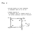
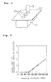
- the hollow depth on flat surface needs to be 0.5 mm or less (the definition of hollow depth on flat surface is shown in Fig. 2 , as a specific measurement method, the hollow depths on the flat surfaces of the complex cross-section forming article were measured with a laser distance meter, and the largest hollow depth was defined as the hollow depth on flat surface). If the hollow depth on flat surface of the product exceeds 0.5 mm, for example, when a steel sheet 12 is pressed against a product 11 by a spot welding electrode 3, as illustrated in Fig. 3 , a relatively large gap ⁇ is easily formed between the steel sheet 12 and the product 11 in an area just below the electrode 3. Hence, a stable current-carrying state cannot be obtained, and failure is likely to occur in spot welding.
- the corner curvature radius R of the article is set to be 10 mm or less (the definition of the corner curvature radius R is shown in Fig. 2 , as a specific measurement method, the complex cross-section forming article was cut along a plane perpendicular to the longitudinal direction, cross-sectional photographs of all corners were taken into images, circles having various curvature radii were superimposed on the corners to find curvature radii R of all the corners, and the largest curvature radius R was set as the corner curvature radius R).
- both the hollow depth on flat surface and the corner curvature radius R decreased as the maximum internal pressure increased and that the higher one of the maximum internal pressure for the hollow depth on flat surface of 0.5 mm and the maximum internal pressure for the corner curvature radius R of 10 mm was preferably set as the lower limit of the maximum internal pressure.
- the relationship between this lower limit and TS of the tubing material is shown in Fig. 4 .
- the lower limit P min of the maximum internal pressure is given by the above-described Expression (1) when TS is 590 MPa or more.
- forming is preferably performed so that the increasing rate of girth after forming becomes 2.0 to 10.0% under the condition that the maximum internal pressure after crushing is P min [MPa] or more.
- forming is performed by using a combination of dies and a tubing material such that an inner girth L K of the cross section of the dies during closing the dies and an outer girth L P of the tubing material before hydroforming satisfy the following relational expression.
- the correspondence relationship between the maximum internal pressure and the increasing rate of girth is found beforehand by FEM (finite element method) analysis or by experiment, and the internal pressure for use in forming after crushing is set at the maximum internal pressure corresponding to the target increasing rate of girth in this correspondence relationship.
- an internal pressure which satisfies the condition that the maximum internal pressure is higher than or equal to P min [MPa] specified by the above Expression (1) and is higher than 50 MPa, is loaded in the tubing material by the liquid while continuing closing of the dies, whereby hydroforming is performed so that the increasing rate of girth after forming is higher than or equal to the below-described A% and is lower than or equal to 11.0%.
- the increasing rate of girth is given by the following expression.
- the flat-surface hollows are further reduced, and the corners R have a more sharply rounded shape (having a smaller curvature radius) because the material (material of tubing material) expands thereat.
- the coefficient on the right side of Expression (4) from 4.167 ⁇ 10 -3 to 4.8 ⁇ 10 -3 , because this improves the shape of the article (the flat-surface hollows and the corners R).
- the maximum internal pressure at closing of the dies is preferably higher than 50 MPa so as to satisfy the condition that the maximum internal pressure is higher than both P min and 50 MPa.
- P min is higher than 50 MPa for the maximum internal pressure.
- the maximum internal pressure at closing of the dies is preferably higher than or equal to P min .
- the thicknesses of portions near the corners R excessively decrease because of expansion of the material.
- the decrease in thickness can be suppressed by applying compression force in the tube axis direction to the tube end so as to push the tube end toward the center in the tube axis direction (this is referred to as "axial feeding"), in addition to the loading of internal pressure after crushing.
- axial feeding the cylinder stroke of the axial feeding pressing machine is adjusted so that the axial feeding length (stroke) is about 0 to 10% of the forming portion length of the end product subjected to the hydroform process.
- the ratio t/D of the thickness to outer diameter of the steel tube used as the tubing material exceeds 0.05, the hollow depth on flat surface tends to increase as t/D increases.
- a steel tube having a value t/D of 0.05 or less is preferably used as the tubing material.
- the increasing rate of girth is preferably 11.0% or less when TS is 690 MPa or more. Further, the increasing rate of girth is preferably 10.0% or less when TS is 780 MPa or more.
- forming is preferably performed so that the increasing rate of girth after forming becomes A to 11.0%. Further, when TS of the tubing material is 780 MPa or more, forming is preferably performed so that the increasing rate of girth after forming becomes A to 10.0%.
- Tubing materials to which the forming method of this application is applicable are electric resistance welded steel tubes that are formed from a hot-rolled steel sheet or a cold-rolled steel sheet having a value TS of 590 MPa or more, and include an electric resistance welded steel tube formed from a hot-rolled steel sheet or a cold-rolled steel sheet subjected to heat treatment such as hardening and tempering.
- the steel type of the above-described hot-rolled steel sheet and cold-rolled steel sheet may be common steel, low-alloy steel, ferritic stainless steel, austenitic stainless steel, or martensitic stainless steel. The steel type is not limited to these steels.
- Tubing materials having values TS and sizes shown in Table 1 were formed into a complex cross-section shape with the dies 1 and 1A of rectangular cross section illustrated in Fig. 1 through the following procedure. All of the used tubing materials are electric resistance welded steel tubes. Table 2 shows compositions and production methods of steel sheets serving as the stocks (or element tube) of the electric resistance welded steel tubes No. 1 to No. 32. The length of the tubing materials used in the example was 300 mm. Procedure: insert in the dies ⁇ crush by closing the dies in a state in which there is no internal pressure or a state in which internal pressures of 50 MPa or less (10 MPa and 13 MPa for No. 10 and No.
- a steel sheet 12 is placed on an upper flat surface of a product 11 and an electrode 3 is pressed against the steel sheet 12 from above with a fixed pressing force (50 to 200 Kgf), whereby one-side spot welding is performed at three points (welding conditions: current-carrying time 10 to 20 cycles (50 Hz), welding current 5 to 10 KA).
- Spot weldability is evaluated on the basis of the presence or absence of nugget formation and the tensile shear load in a tensile shear test (JIS Z 3136), and is evaluated on a scale of two grades, that is, ⁇ G:Good and ⁇ P:Poor.
- a reference value TSS of the tensile shear load of a joint is based on the following expression, and a joint that meets the reference value is judged sufficient (acceptable).
- TSS N 1.85 ⁇ t ⁇ TS ⁇ 1 + 0.0059 ⁇ EL ⁇ ND + 2.09 t: thickness of steel sheet 12 (mm)
- TS tensile strength of steel sheet 12 (MPa)
- EL elongation of steel sheet 12 (%)
- ND nugget diameter between product 11 and steel sheet 12 (mm)
- the steel sheet 12 is a steel sheet having a thickness of 1.0 mm or less and a tensile strength of 440 MPa or less.
- Table 1 shows the results of the above measurement and test. Table 1 shows that complex cross-section forming articles having high spot weldability and high dimensional accuracy were obtained from tubing materials having values TS of 590 MPa or more in the example of the present invention. In the example of the present invention, the hollow depths on flat surface of the tubing materials having values t/D ⁇ 0.05 are smaller than those of the tubing materials having values t/D > 0.05.
- tubing materials having values TS and sizes shown in Table 3 were formed into complex cross-section shapes with the dies 1 and 1A of rectangular cross section illustrated in Fig. 1 .
- All of the used tubing materials are electric resistance welded steel tubes.
- Table 4 shows the compositions and production methods of steel sheets serving as the stocks of the electric resistance welded steel tubes No. 1 to No. 30.
- the length of the steel tubes used in the example was 300 mm.
- the hollow depths on flat surface and corner curvature radii R (see Fig. 2 ) of obtained articles were measured, and a test for spot weldability was conducted by a method similar to that adopted in the first example.
- Table 3 shows the results of the above measurement and test. Table 3 shows that complex cross-section forming articles having high spot weldability and high dimensional accuracy were obtained from tubing materials having values TS of 690 MPa or more in the example of the present invention.
- the hollow depths on flat surface of the tubing materials having values t/D ⁇ 0.05 are smaller than those of the tubing materials having values t/D > 0.05.
- forming is performed by continuously loading internal pressure by the liquid in a tubing material so that the maximum internal pressure is within a proper range, more preferably, so that the increasing rate of girth after forming is within a proper range, whereby the tubing material can be formed into a complex cross-section shape having a small hollow depth on flat surface and a corner curvature radius R for a sharp outline (small curvature radius). Since the obtained complex cross-section forming article has a small hollow depth on flat surface, it is excellent in one-side spot weldability to a metallic sheet. Moreover, springback deformation after removal of the pressure is suppressed, and the complex cross-section forming article has high dimensional accuracy.
Landscapes
- Engineering & Computer Science (AREA)
- Mechanical Engineering (AREA)
- Physics & Mathematics (AREA)
- Fluid Mechanics (AREA)
- Shaping Metal By Deep-Drawing, Or The Like (AREA)
Abstract
Description
- The present invention relates to a forming method of complex cross-section shape (or shape tube)and a quadrate cross-section forming article having high spot weldability, and more particularly, relates to a forming method of complex cross-section shape that forms a tubing material serving as a stock (or element tube)into a complex cross-section shape by a hydroform process, and to a quadrate cross-section forming article with high spot weldability which is formed from a tubing material by the forming method and which has one or two pairs of parallel sides.
- Methods for forming a tubing material serving as a stock into a complex cross-section shape by the hydroform process are known (for example, see paragraphs [0003] to [0005] in the description of the related art and
Figs. 1 and2 in Patent Document 1). In a disclosed first type method, as illustrated inFig. 1 (a) of Patent Document 1, a pipe of circular cross section is subjected to bending (referred to as preforming in the present invention) to have a required planar shape, for example, into a U-shape illustrated in Fig. 3(b) of Patent Document 1. A portion corresponding to a product portion having a width smaller than the pipe diameter of the bent article is subjected to crushing into a cross-section shape having a width smaller than the stock diameter (or diameter of element tube) by a pressing machine or a dedicated machine, as illustrated inFig. 1 (b) of Patent Document. This crushed article is set in a cavity between upper and lower dies, as illustrated inFig. 1 (c) of Patent Document 1, and the upper and lower dies are closed, as illustrated in Fig. 1 (d) of Patent Document 1. After that, liquid is injected into the crushed article, as illustrated in Fig. 1 (e) of Patent Document 1 so as to load an internal pressure of, for example, 22000 psi (151 MPa), whereby the article is plastically deformed to fit surfaces of the dies and is formed into a cross-section shape illustrated in Fig. 1 (f) of Patent Document 1. In a disclosed second type method, as illustrated in Fig. 2(a) of Patent Document 1, a pipe of circular cross section is bent into a required planar shape, for example, into a U-shape illustrated in Fig. 3(b) of Patent Document 1, and the bent article is also subjected to crushing into a cross-section shape having a reduced width by a pressing machine or a dedicated machine, as illustrated in Fig. 2(b) of Patent Document 1. This crushed article is set in a cavity between upper and lower dies, as illustrated in Fig. 2(c) of Patent Document 1, and a low pressure of, for example, about 1000 psi (7MPa) is loaded in the crushed article for prepressurization before closing of dies, as illustrated in Fig. 2(d) of Patent Document 1. Subsequently, closing of dies is performed, as illustrated in Fig. 2(e) of Patent Document 1, and the internal pressure is increased to a high internal pressure of 6000 to 7000 psi (42 to 49 MPa), whereby the prepressurized article is plastically deformed into a cross-section shape illustrated in Fig. 2(f) of Patent Document 1 so as to fit surfaces of the dies. -
- Patent Document 1: Japanese Unexamined Patent Application Publication No.
2000-246361 - However, in the above-described first type forming method of the related art, it is typical to adopt a high increasing rate of girth of 10% or more, and rupture is more likely to occur in a low-ductility tubing material, for example, a high-strength steel tube when a high internal pressure is loaded. In the second type, deep hollows are formed in some portions of the complex cross-section forming article that should be flat (for example, portions serving as sides of a rectangular cross section) by crushing, and this makes spot welding, especially one-side spot welding quite difficult. Further, the curvature radius R of corners R (for example, portions serving as corners of the rectangular cross section) is much larger than that of corresponding corners of the dies. Hence, it is difficult to obtain a sharp cross-section shape, and the form accuracy of the product is insufficient.
- That is, the forming technique of complex cross-section shape of the related art using the hydroform process has difficulty in obtaining a complex cross-section forming article having high spot weldability and high dimensional accuracy.
Here, the complex cross section refers to a cross section different from a circular form cross section, for example, a rectangular cross section. - As a result of earnest studies for overcoming the above-described problem, the present inventors conceived a means that realized a complex cross-section forming article, which allowed easy spot welding, by the hydroform process, and made the present invention. That is, the present invention is as follows:
(1) A forming method of complex cross-section shape characterized in that a tubing material having a tensile strength of 590 MPa or more is crushed by a complex cross-section shape forming die having at least one surface with a flat portion in a state in which no internal pressure is loaded or an internal pressure of 50 MPa or less is loaded in the tubing material by liquid, and is formed into a complex cross-section shape by continuously loading by the liquid, to the tubing material, an internal pressure such that the maximum internal pressure becomes higher than or equal to the following Pmin [MPa]. - Note:

Pmin: lower limit of maximum internal pressure [MPa], TS: tensile strength of tubing material [MPa]
(2) The forming method of complex cross-section shape according to the above (1), characterized in that a tube end is pushed in toward a center in a tube axis direction by applying a compression force in the tube axis direction to the tube end in addition to the loading of the internal pressure after crushing.
(3) The forming method of complex cross-section shape according to the above (1) or (2), characterized in that a steel tube having a tensile strength of 780 MPa or more is used as the tubing material and that the tubing material is formed so that an increasing rate of girth after forming is higher than or equal to 2.0% and lower than or equal to 10.0%.
(4) The forming method of complex cross-section shape according to any of the above (1) to (3), characterized in that a steel tube whose ratio t/D of a thickness to an outer diameter is 0.05 or less is used as the tubing material.
(5) A quadrate cross-section forming article having one or two pairs of parallel sides and having high spot weldability, the quadrate cross-section forming article being formed by the forming method of complex cross-section shape according to any of the above (1) to (4), characterized in that a hollow depth (or denting depth) on flat surface is 0.5 mm or less and a corner curvature radius R is 10 mm or less.
(6) The forming method of complex cross-section shape according to the above (1), characterized in that the tubing material is a tubing material having a tensile strength of 690 MPa or more, that, when the tubing material is crushed by the complex cross-section shape forming die and is formed into the complex cross-section shape by continuously loading the internal pressure by the liquid, the loaded internal pressure is such that the maximum internal pressure is higher than or equal to Pmin and higher than 50 MPa, and that the tubing material is formed so that an increasing rate of girth after forming is higher than or equal to the following A% and lower than or equal to 11.0%. - Note:

A: lower limit of increasing rate of girth (%), TS: tensile strength of tubing material (MPa)
(7) The forming method of complex cross-section shape according to (6), characterized in that a tube end is pushed in toward a center in a tube axis direction by applying a compression force in the tube axis direction to the tube end in addition to the loading of the internal pressure after crushing.
(8) The forming method of complex cross-section shape according to (6) or (7), characterized in that a steel tube having a tensile strength of 780 MPa or more is used as the tubing material, and that the tubing material is formed so that the increasing rate of girth after forming is higher than or equal to the following A% and lower than or equal to 10.0%. - Note:

A: lower limit of increasing rate of girth (%), TS: tensile strength of tubing material (MPa)
(9) The forming method of complex cross-section shape according to any of (6) to (8), characterized in that a steel tube whose ratio t/D of a thickness to an outer diameter is 0.05 or less is used as the tubing material.
(10) A quadrate cross-section forming article having one or two pairs of parallel sides and having high spot weldability, the quadrate cross-section forming article being formed by the forming method of complex cross-section shape according to any of (6) to (9), characterized in that a hollow depth on flat surface is 0.5 mm or less and a corner curvature radius R is 10 mm or less.
(11) A forming method of complex cross-section shape characterized in that a tubing material having a tensile strength of 690 MPa or more is crushed by a complex cross-section shape forming die having at least one surface with a flat portion in a state in which no internal pressure is loaded or an internal pressure of 50 MPa or less is loaded in the tubing material by liquid, and is formed into a complex cross-section shape by continuously loading by the liquid, to the tubing material, an internal pressure such that the maximum internal pressure is higher than 50 MPa, and that the tubing material is formed so that an increasing rate of girth after forming is higher than or equal to the following A% and lower than or equal to 11.0%.
Note:
A: lower limit of increasing rate of girth (%), TS: tensile strength of tubing material (MPa)
(12) The forming method of complex cross-section shape according to the above (11), characterized in that a tube end is pushed in toward a center in a tube axis direction by applying a compression force in the tube axis direction to the tube end in addition to the loading of the internal pressure after crushing.
(13) The forming method of complex cross-section shape according to the above (11) or (12), characterized in that a steel tube having a tensile strength of 780 MPa or more is used as the tubing material and that the tubing material is formed so that the increasing rate of girth after forming is higher than or equal to the following A% and lower than or equal to 10.0%.
Note:
A: lower limit of increasing rate of girth (%), TS: tensile strength of tubing material (MPa)
(14) The forming method of complex cross-section shape according to any of the above (11) to (13), characterized in that a steel tube whose ratio t/D of a thickness to an outer diameter is 0.05 or less is used as the tubing material.
(15) A quadrate cross-section forming article having one or two pairs of parallel sides and having high spot weldability, the quadrate cross-section forming article being formed by the forming method of complex cross-section shape according to any of the above (11) to (14), characterized in that a hollow depth on flat surface is 0.5 mm or less and a corner curvature radius R is 10 mm or less. - According to the present invention, after a tubing material is crushed by upper and lower forming dies, an internal pressure is continuously loaded in the tubing material by liquid, and the tubing material is formed so that the maximum internal pressure is within a proper range, preferably, so that an increasing rate of girth after forming is within a proper range. This allows the tubing material to be formed into a complex cross-section shape having a small hollow depth on flat surface and corner curvature radius R that provides a sharp outline (with a small curvature radius). Since an obtained complex cross-section forming article has a small hollow depth on flat surface, it is excellent in one-side spot weldability to a metallic sheet. Moreover, springback deformation after removal of the pressure is suppressed, and the complex cross-section forming article has high dimensional accuracy. Brief Description of Drawings
-
- [
Fig. 1] Fig. 1 includes explanatory views schematically illustrating a method of the present invention. - [
Fig. 2] Fig. 2 is an explanatory view showing definitions of the hollow depth on flat surface and the corner curvature radius R of a quadrate cross-section forming article having one or two pairs of parallel sides. - [
Fig. 3] Fig. 3 is an explanatory view illustrating a state in which trouble occurs to one-side spot welding. - [
Fig. 4] Fig. 4 is a graph showing the relationship between the lower limit of the maximum internal pressure and the tensile strength. - [
Fig. 5] Fig. 5 is an explanatory view illustrating a method of a spot welding experiment. - [
Fig. 6] Fig. 6 is a graph showing the relationship between the lower limit of the increasing rate of girth and the tensile strength. -
Fig. 1 includes explanatory views schematically illustrating a method of the present invention. Atubing material 10 is formed by a metallic tube, such as a steel tube, having a tensile strength (abbreviated as TS) of 590 MPa or more. First, as illustrated inFig. 1 (a) , thetubing material 10 is set in a die having at least one flat surface, for example, a pair of upper andlower dies 1 and 1A having flat surfaces. The cross-section shape of thedies 1 and 1A is different from that of thetubing material 10. Thetubing material 10 can or cannot be subjected to preforming. In the present invention, as described above, the term preforming refers to bending the tubing material into a U-shape in the longitudinal direction, as illustrated in Fig. 3(b) of Patent Document 1, bending into an S-shape, bending at 90°, crushing a longitudinal part of the tubing material, or local tube expansion or contraction. Then, the tubing material is crushed by the upper and lower dies 1 and 1A in a state in which no internal pressure is loaded in the tubing material or a low internal pressure (50 MPa or less) is loaded therein by liquid. - In the method of the present invention, the case in which no internal pressure is loaded in the tubing material includes two cases, that is, a case in which there is no liquid in the pipe and a case in which no internal pressure is produced even when there is liquid in the pipe. In general, to shorten the cycle time of hydroforming, preparation is made by liquid injection (bubbles are removed while filling the pipe with liquid) while performing crushing.
- Then, as illustrated in
Fig. 1 (b) , hollows (referred to as flat-surface hollows) are formed in tube wall portions facing the flat surfaces of the dies, and gentle corners R are formed in tube wall portions facing the corners of the dies. - Accordingly, an internal pressure such that the maximum internal pressure is higher than or equal to the following pressure Pmin [MPa] is continuously loaded in the tubing material by the liquid while continuing closing of dies, so that the tubing material is formed into a complex cross-section shape (
Fig. 1 (c) ).
Note:
Pmin: lower limit of maximum internal pressure [MPa], TS: tensile strength of tubing material [MPa]
Thus, as illustrated inFig. 1 (c) , the flat-surface hollows are reduced, and the corners R become sharp because the material (material of the tubing material) expands thereat. Further, the residual stress decreases as the maximum internal pressure increases, and the shape change due to springback after removal of the pressure decreases. - In Expression (1), the coefficient of 0.045 on the right side is preferably replaced with 0.09, more preferably replaced with 0.12, because this further improves the shape of the article.
- The maximum internal pressure is usually about 100 to 200 MPa for the following reason. The performance of a pressure intensifier for applying the internal pressure is usually up to 200 MPa. If the projection area of the article in a horizontal plane (or the projection area of the die cavity) is excessively large, the performance is sometimes set to be less than 200 MPa, for example, 150 MPa because of the limit of the pressing force of the pressure intensifier. When the above limit is not made and a tube stock (or element tube) is thin and has a low strength, sufficient corrective forming is sometimes possible at 100 MPa.
- When the internal pressure is loaded after crushing, it is conceivable that the thicknesses of portions near the corners R excessively decrease because of expansion of the material. In such a case, the decrease in thickness can be suppressed by applying compression force in the tube axis direction to a tube end so as to push the tube end toward the center in the tube axis direction (this is referred to as "axial feeding"), in addition to the loading of internal pressure after crushing. As an actual timing to perform axial feeding, axial feeding is preferably performed after a short time elapses from the loading of internal pressure, and axial feeding is not performed simultaneously with the loading of internal pressure. As a preferred condition of "axial feeding", the cylinder stroke of an axial feeding pressing machine is adjusted so that the axial feeding length (stroke) is about 0 to 2% of the forming portion length L of an end product after the hydroform process when the ratio L/D of the forming portion length L and the tube stock (or element tube)outer diameter D is higher than or equal to about 10, so that the axial feeding length is about 0 to 3.5% of the length L when L/D is higher than 7 and less than 10, and so that the axial feeding length is 0 to 5% of the length L when L/D is lower than or equal to 7. When the internal pressure is loaded, the axial feeding pressing machine tends to be pushed back by reactive force applied thereto. Hence, an axial feeding force exists even when the axial feeding length is 0%.
- In the present invention, when a steel tube having a tensile strength of 780 MPa or more is used as the tubing material, forming is preferably performed so that the increasing rate of girth after forming becomes higher than or equal to 2.0% and lower than or equal to 10.0%.
The increasing rate of girth is given by the following Expression (2):
- When the ratio t/D of the thickness to the outer diameter of the steel tube used for the tubing material exceeds 0.05, the hollow depth on flat surface tends to increase as t/D increases. Hence, a steel tube having a ratio t/D of 0.05 or less is preferably used as the tubing material.
- According to the above-described method of the present invention, it is possible to obtain a complex cross-section forming article having high spot weldability and high dimensional accuracy. In order for this article (product) to have high one-side spot weldability, the hollow depth on flat surface needs to be 0.5 mm or less (the definition of hollow depth on flat surface is shown in
Fig. 2 , as a specific measurement method, the hollow depths on the flat surfaces of the complex cross-section forming article were measured with a laser distance meter, and the largest hollow depth was defined as the hollow depth on flat surface). If the hollow depth on flat surface of the product exceeds 0.5 mm, for example, when asteel sheet 12 is pressed against aproduct 11 by a spot welding electrode 3, as illustrated inFig. 3 , a relatively large gap δ is easily formed between thesteel sheet 12 and theproduct 11 in an area just below the electrode 3. Hence, a stable current-carrying state cannot be obtained, and failure is likely to occur in spot welding. - Further, in order for a quadrate cross-section forming article having one or two pairs of parallel sides to have high dimensional accuracy, a sharply rounded shape is necessary. In the present invention, the corner curvature radius R of the article is set to be 10 mm or less (the definition of the corner curvature radius R is shown in
Fig. 2 , as a specific measurement method, the complex cross-section forming article was cut along a plane perpendicular to the longitudinal direction, cross-sectional photographs of all corners were taken into images, circles having various curvature radii were superimposed on the corners to find curvature radii R of all the corners, and the largest curvature radius R was set as the corner curvature radius R). - Here, the reason why the lower limit Pmin [MPa] of the internal pressure (maximum internal pressure) when the internal pressure to be loaded after crushing becomes the highest is specified as the value of Expression (1) described above in the present invention will be explained. Studies were made on the forming condition for obtaining a hollow depth on flat surface of the article of 0.5 mm or less and a corner curvature radius R of 10 mm or less in a case in which tubing materials having various values TS were crushed by the dies and were then formed into a quadrate cross-section shape having one or two pairs of parallel sides by loading the internal pressure by the liquid. As a result, it was found that both the hollow depth on flat surface and the corner curvature radius R decreased as the maximum internal pressure increased and that the higher one of the maximum internal pressure for the hollow depth on flat surface of 0.5 mm and the maximum internal pressure for the corner curvature radius R of 10 mm was preferably set as the lower limit of the maximum internal pressure. The relationship between this lower limit and TS of the tubing material is shown in
Fig. 4 . InFig. 4 , the lower limit Pmin of the maximum internal pressure is given by the above-described Expression (1) when TS is 590 MPa or more. - Further, with attention to the increasing rate of girth, the dependencies of the hollow depth on flat surface and the corner curvature radius R on the increasing rate of girth were found, and the following findings were obtained. That is, when TS of the tubing material is 780 MPa or more under the condition that the maximum internal pressure after crushing is the above-described value Pmin or more, if the increasing rate of girth of the product is 2.0% or more, the hollow depth on flat surface is markedly small. If the increasing rate of girth of the product is 10.0% or less, the corner curvature radius R is markedly small.
- Therefore, when TS of the tubing material is 780 MPa, forming is preferably performed so that the increasing rate of girth after forming becomes 2.0 to 10.0% under the condition that the maximum internal pressure after crushing is Pmin [MPa] or more.
- To keep the increasing rate of girth within a predetermined range (higher than or equal to A% and lower than or equal to B%), forming is performed by using a combination of dies and a tubing material such that an inner girth LK of the cross section of the dies during closing the dies and an outer girth LP of the tubing material before hydroforming satisfy the following relational expression.
-

- Further, in the present invention, when the
tubing material 10 having a tensile strength of 690 MPa or more is used, as described above, an internal pressure, which satisfies the condition that the maximum internal pressure is higher than or equal to Pmin [MPa] specified by the above Expression (1) and is higher than 50 MPa, is loaded in the tubing material by the liquid while continuing closing of the dies, whereby hydroforming is performed so that the increasing rate of girth after forming is higher than or equal to the below-described A% and is lower than or equal to 11.0%. The increasing rate of girth is given by the following expression. -

Note:
A: lower limit of increasing rate of girth (%), TS: tensile strength of tubing material (MPa) - In this way, as illustrated in
Fig. 1 (c) , the flat-surface hollows are further reduced, and the corners R have a more sharply rounded shape (having a smaller curvature radius) because the material (material of tubing material) expands thereat. Further, as the maximum internal pressure increases, the residual stress decreases, and the shape change due to springback caused after the pressure is removed decreases. It is preferable to change the coefficient on the right side of Expression (4) from 4.167×10⁻³ to 4.8×10⁻³, because this improves the shape of the article (the flat-surface hollows and the corners R). - In the present invention, when the tensile strength TS of the tubing material is within the range of 690 to 1100 MPa, 50 MPa is higher than the above-described Pmin for the maximum internal pressure. Hence, the maximum internal pressure at closing of the dies is preferably higher than 50 MPa so as to satisfy the condition that the maximum internal pressure is higher than both Pmin and 50 MPa. Further, when TS exceeds 1100 MPa, Pmin is higher than 50 MPa for the maximum internal pressure. Hence, the maximum internal pressure at closing of the dies is preferably higher than or equal to Pmin.
- When the internal pressure is loaded after crushing, it is conceivable that the thicknesses of portions near the corners R excessively decrease because of expansion of the material. In such a case, the decrease in thickness can be suppressed by applying compression force in the tube axis direction to the tube end so as to push the tube end toward the center in the tube axis direction (this is referred to as "axial feeding"), in addition to the loading of internal pressure after crushing. As a preferred condition of "axial feeding", the cylinder stroke of the axial feeding pressing machine is adjusted so that the axial feeding length (stroke) is about 0 to 10% of the forming portion length of the end product subjected to the hydroform process.
- If the ratio t/D of the thickness to outer diameter of the steel tube used as the tubing material exceeds 0.05, the hollow depth on flat surface tends to increase as t/D increases. Hence, a steel tube having a value t/D of 0.05 or less is preferably used as the tubing material.
- Here, the reason why forming is performed so that the increasing rate of girth after forming is higher than or equal to A% and lower than or equal to 11.0% in the present invention will now be explained. Studies were made on a forming condition for obtaining a hollow depth on flat surface of 0.5 mm or less of the article and a corner curvature radius R of 10 mm or less when tubing materials having various values TS were crushed by the dies and were then formed into a quadrate cross-section shape having one or two pairs of parallel sides by the loading of internal pressure from the liquid. As a result, it was found that the hollow depth on flat surface decreased as the increasing rate of girth increased and that the increasing rate of girth became the lower limit when the flat-surface hollow depth was 0.5 mm. The relationship between this lower limit and TS of the tubing material is shown in
Fig. 6 . InFig. 6 , the lower limit A of the increasing rate of girth is given by the above Expression (4) when TS is 690 MPa or more. - In contrast, it was found that the corner curvature radius R decreased as the increasing rate of girth increased and that the increasing rate of girth became the upper limit when the corner curvature radius R was 10 mm. According to the found relationship between this upper limit and TS of the tubing material (not shown), the increasing rate of girth is preferably 11.0% or less when TS is 690 MPa or more. Further, the increasing rate of girth is preferably 10.0% or less when TS is 780 MPa or more.
- Therefore, when TS of the tubing material is 690 MPa or more, forming is preferably performed so that the increasing rate of girth after forming becomes A to 11.0%. Further, when TS of the tubing material is 780 MPa or more, forming is preferably performed so that the increasing rate of girth after forming becomes A to 10.0%.
- Tubing materials to which the forming method of this application is applicable are electric resistance welded steel tubes that are formed from a hot-rolled steel sheet or a cold-rolled steel sheet having a value TS of 590 MPa or more, and include an electric resistance welded steel tube formed from a hot-rolled steel sheet or a cold-rolled steel sheet subjected to heat treatment such as hardening and tempering. The steel type of the above-described hot-rolled steel sheet and cold-rolled steel sheet may be common steel, low-alloy steel, ferritic stainless steel, austenitic stainless steel, or martensitic stainless steel. The steel type is not limited to these steels.
- Tubing materials having values TS and sizes shown in Table 1 were formed into a complex cross-section shape with the dies 1 and 1A of rectangular cross section illustrated in
Fig. 1 through the following procedure. All of the used tubing materials are electric resistance welded steel tubes. Table 2 shows compositions and production methods of steel sheets serving as the stocks (or element tube) of the electric resistance welded steel tubes No. 1 to No. 32. The length of the tubing materials used in the example was 300 mm. Procedure: insert in the dies → crush by closing the dies in a state in which there is no internal pressure or a state in which internal pressures of 50 MPa or less (10 MPa and 13 MPa for No. 10 and No. 11, respectively) are loaded by liquid → load internal pressures such that the maximum internal pressure becomes values in Table 1, by the liquid so that various increasing rates of girth shown in Table 1 are obtained (some tubing materials are also subjected to axial feeding (the axial feeding lengths of No. 12 and No. 13 are 2.5% or 3.0%, respectively)). - Hollow depths on flat surface and corner curvature radii R of obtained articles (products) (see
Fig. 2 ) were measured (for measurement of the hollow depths on flat surface, the hollow depths on four flat surfaces at the longitudinal centers of each complex cross-section forming article were measured with a laser distance meter provided in the direction perpendicular to the longitudinal direction, the largest hollow depth was set as the hollow depth on flat surface, and, for measurement of the corner curvature radii R, each complex cross-section forming article was cut along a plane perpendicular to the longitudinal direction at the longitudinal centers, cross-sectional photographs of four corners were taken into images, circles having various radii were superimposed on the corners, whereby the curvature radii R of the four corners were found, and the largest curvature radius R was set as the corner curvature radius R). Also, a test for spot weldability was conducted by the following method. - As illustrated in
Fig. 5 , asteel sheet 12 is placed on an upper flat surface of aproduct 11 and an electrode 3 is pressed against thesteel sheet 12 from above with a fixed pressing force (50 to 200 Kgf), whereby one-side spot welding is performed at three points (welding conditions: current-carryingtime 10 to 20 cycles (50 Hz), welding current 5 to 10 KA). Spot weldability is evaluated on the basis of the presence or absence of nugget formation and the tensile shear load in a tensile shear test (JIS Z 3136), and is evaluated on a scale of two grades, that is, ○ G:Good and × P:Poor. A reference value TSS of the tensile shear load of a joint is based on the following expression, and a joint that meets the reference value is judged sufficient (acceptable).
t: thickness of steel sheet 12 (mm)
TS: tensile strength of steel sheet 12 (MPa)
EL: elongation of steel sheet 12 (%)
ND: nugget diameter betweenproduct 11 and steel sheet 12 (mm)
Thesteel sheet 12 is a steel sheet having a thickness of 1.0 mm or less and a tensile strength of 440 MPa or less.
○ G(Good): Nugget formation is found at spot welded portions 13 (the presence or absence of nugget formation is determined by a cross-sectional photograph), and the tensile shear load is sufficient (acceptable)
× P(Poor): Nugget formation is not found at the spot weldedportions 13, or the tensile shear load is insufficient. - Table 1 shows the results of the above measurement and test. Table 1 shows that complex cross-section forming articles having high spot weldability and high dimensional accuracy were obtained from tubing materials having values TS of 590 MPa or more in the example of the present invention. In the example of the present invention, the hollow depths on flat surface of the tubing materials having values t/D ≤ 0.05 are smaller than those of the tubing materials having values t/D > 0.05.
- Similarly to the first example, tubing materials having values TS and sizes shown in Table 3 were formed into complex cross-section shapes with the dies 1 and 1A of rectangular cross section illustrated in
Fig. 1 . All of the used tubing materials are electric resistance welded steel tubes. Table 4 shows the compositions and production methods of steel sheets serving as the stocks of the electric resistance welded steel tubes No. 1 to No. 30. The length of the steel tubes used in the example was 300 mm. Procedure: insert in the dies → crush by closing the dies in a state in which there is no internal pressure or a state in which internal pressures of 50 MPa or less (10 MPa and 13 MPa for No. 8 and No. 9, respectively) are loaded by liquid → load internal pressures higher than 50 MPa by the liquid so that various increasing rates of girth shown in Table 3 are obtained (some tubing materials are also subjected to axial feeding (the axial feeding lengths of No. 10 and No. 11 are 4% or 5%, respectively)). - The hollow depths on flat surface and corner curvature radii R (see
Fig. 2 ) of obtained articles were measured, and a test for spot weldability was conducted by a method similar to that adopted in the first example.
Table 3 shows the results of the above measurement and test. Table 3 shows that complex cross-section forming articles having high spot weldability and high dimensional accuracy were obtained from tubing materials having values TS of 690 MPa or more in the example of the present invention. In the example of the present invention, the hollow depths on flat surface of the tubing materials having values t/D ≤ 0.05 are smaller than those of the tubing materials having values t/D > 0.05. - According to the present invention, subsequently to crushing with the upper and lower forming dies, forming is performed by continuously loading internal pressure by the liquid in a tubing material so that the maximum internal pressure is within a proper range, more preferably, so that the increasing rate of girth after forming is within a proper range, whereby the tubing material can be formed into a complex cross-section shape having a small hollow depth on flat surface and a corner curvature radius R for a sharp outline (small curvature radius). Since the obtained complex cross-section forming article has a small hollow depth on flat surface, it is excellent in one-side spot weldability to a metallic sheet. Moreover, springback deformation after removal of the pressure is suppressed, and the complex cross-section forming article has high dimensional accuracy.
-
- 1 die (upper die)
- 1A die (lower die)
- 3 electrode
- 10 tubing material
- 11 product (complex cross-section forming article, quadrate cross-section forming article having one or two pairs of parallel sides)
- 12 steel sheet
- 13 spot welded portion
-
Table 1-1 No TS outer
diameter
Dthickness
tt/D internal
pressure
before
crushingaxial
feedingmaximum
internal
pressure
after
crushingincreasing
rate of
girthhollow
depth on
flat
surfacecorner R spot
weld-abilityremarks (MPa) (mm) (mm) (Mpa) (%) (mm) (mm) 1 610 48 2 0.042 not loaded not performed 50 2.8 0.33 6.9 ○ G invention example 2 820 48 2 0.042 not loaded not performed 70 2.8 0.36 7.2 ○ G invention example 3 1090 48 2 0.042 not loaded not performed 100 2.8 0.33 7.4 ○ G invention example 4 1310 48 2 0.042 not loaded not performed 120 2.8 0.45 8 ○ G invention example 5 820 48 2 0.042 not loaded not performed 200 2.8 0.2 7.1 ○ G invention example 6 1090 48 2 0.042 not loaded not performed 200 2.8 0.22 7.2 ○ G invention example 7 610 48 2 0.042 not loaded not performed 200 5.1 0.14 7.5 ○ G invention example 8 820 48 2 0.042 not loaded not performed 200 5.1 0.05 7.9 ○ G invention example 9 1090 48 2 0.042 not loaded not performed 200 5.1 0.04 8.2 ○ G invention example 10 820 48 2 0.042 loaded not performed 70 2.8 0.04 7.5 ○ G invention example 11 1090 48 2 0.042 loaded not performed 100 2.8 0.06 7.8 ○ G invention example 12 610 48 2 0.042 not loaded performed 70 2.8 0.31 6.7 ○ G invention example 13 820 48 2 0.042 not loaded performed 100 2.8 0.37 7 ○ G invention example 14 610 48 2.4 0.05 not loaded not performed 50 2.8 0.36 7 ○ G invention example 15 820 48 2.4 0.05 not loaded not performed 70 2.8 0.4 7.3 ○ G invention example 16 1090 48 2.4 0.05 not loaded not performed 100 2.8 0.37 7.6 ○ G invention example -
Table 1-2 No TS outer
diameter
Dthickness
tt/D internal
pressure
before
crushingaxial
feedingmaximum
internal
pressure
after
crushingincreasing
rate of
girthhollow
depth on
flat
surfacecorner R spot
weld-abilityremarks (MPa) (mm) (mm) (Mpa) (%) (mm) (mm) 17 610 48 1 0.021 not loaded not performed 50 2.8 0.27 O G invention example 18 820 48 1 0.021 not loaded not performed 70 2.8 0.33 7.2 O G invention example 19 1090 48 1 0.021 not loaded not performed 100 2.8 0.25 7.5 O G invention example 20 610 70 3.5 0.05 not loaded not performed 50 2.8 0.39 7.2 O G invention example 21 820 70 3.5 0.05 loaded not performed 70 2.8 0.42 7.5 O G invention example 22 1090 70 3.5 0.05 loaded not performed 100 2.8 0.41 7.7 O G invention example 23 610 70 3 0.043 not loaded not performed 50 2.8 0.36 7 O G invention example 24 820 70 3 0.043 not loaded not performed 70 2.8 0.4 7.4 O G invention example 25 1090 70 3 0.043 loaded not performed 100 2.8 0.39 7.6 O G invention example 26 610 70 1.4 0.02 loaded not performed 50 2.8 0.3 6.8 O G invention example 27 820 70 1.4 0.02 loaded not performed 70 2.8 0.35 7 O G invention example 28 1090 70 1.4 0.02 loaded not performed 100 2.8 0.29 7.1 O G invention example 29 610 48 2 0.042 not loaded not performed 10 2.8 0.69 6.9 × P comparative example 30 820 48 2 0.042 not loaded not performed 20 2.8 0.7 6.9 × P comparative example 31 1090 48 2 0.042 not loaded not performed 30 2.8 0.75 8.2 × P comparative example 32 1310 48 2 0.042 not loaded not performed 40 2.8 0.77 8.2 × P comparative example -
Table 2 No. in first
exampleTS (MPa) outer
diameter
D
(mm)thickness
t
(mm)production
method for
steel tubeproduction
method for
steel tube
raw sheetcomposition of steel tube stock (mass %) C Si Mn Nb Cr Ti Mo 1,7,12,29 610 48 2.0 electric
resistance
welded steel
tubehot-rolled
steel sheet0.1 0.2 1.3 0.039 0.036 0,01 - 14 610 48 2.4 17 610 48 1.0 20 610 70 3.5 23 610 70 3.0 26 610 70 1.4 2,5,8,10,13,30 820 48 2.0 electric
resistance
welded steel
tubehot-rolled sheet 0.1 0.3 1.6 0.03 0.12 0.07 0.15 15 820 48 2.4 18 820 48 1.0 21 820 70 3.5 24 820 70 3.0 27 820 70 1.4 3,6,9,11,31 1090 48 2.0 electric
resistance
welded steel
tubecold-rolled
steel sheet,
heat
treatment
(water
hardening,
tempering)0.12 1.4 1.9 - - - - 16 1090 48 2.4 19 1090 48 1.0 22 1090 70 3.5 25 1090 70 3.0 28 1090 70 1.4 4.32 1310 48 2.0 electric
resistance
welded steel
tubecold-rolled
steel sheet,
heat
treatment
(water
hardening,
tempering)0.13 1.4 2.2 - - - - -
Table 3-1 No TS outer
diameter
Dthickness
tt/D internal
pressure
before
crushingaxial
feedingmaximum
internal
pressure
after
crushingincreasing
rate of
girthhollow
depth on
flat
surfacecorner R spot
weld-abilityremarks (MPa) (mm) (mm) (Mpa) (%) (mm) (mm) 1 710 48 2.0 0.042 not loaded not performed 200 0.70 0.27 6.6 ○ G invention example 2 840 48 2.0 0.042 not loaded not performed 200 1.40 0.28 7.1 ○ G invention example 3 1100 48 2.0 0.042 not loaded not performed 200 2.80 0.17 7.3 ○ G invention example 4 1300 48 2.0 0.042 not loaded not performed 200 3.00 0.21 8.5 ○ G invention example 5 710 48 2.0 0.042 not loaded not performed 75 2.80 0.38 7.0 ○ G invention example 6 840 48 2.0 0.042 not loaded not performed 100 2.80 0.47 7.2 ○ G invention example 7 1100 48 2.0 0.042 not loaded not performed 150 2.80 0.33 7.4 ○ G invention example 8 840 48 2.0 0.042 loaded not performed 200 1.40 0.09 7.6 ○ G invention example 9 1100 48 2.0 0.042 loaded not performed 200 2.80 0.10 7.9 ○ G invention example 10 710 48 2.0 0.042 not loaded performed 200 0.70 0.29 6.4 ○ G invention example 11 840 48 2.0 0.042 not loaded performed 200 1.40 0.30 6.9 ○ G invention example 12 710 48 2.4 0.050 not loaded not performed 200 0.70 0.32 6.6 ○ G invention example 13 840 48 2.4 0.050 not loaded not performed 200 1.40 0.34 7.2 ○ G invention example 14 1100 48 2.4 0.050 not loaded not performed 200 2.80 0.25 7.4 ○ G invention example 15 710 48 1.0 0.021 not loaded not performed 200 0.70 0.18 6.4 ○ G invention example -
Table 3-2 No TS outer
diameter
Dthickness
tt/D internal
pressure
before
crushingaxial
feedingmaximum
internal
pressure
after
crushingincreasing
rate of
girthhollow
depth on
flat
surfacecorner R spot
weld-abilityremarks (MPa) (mm) (mm) (Mpa) (%) (mm) (mm) 16 840 48 1.0 0.021 not loaded not performed 200 1.40 017 70 O G invention example 17 1100 48 1.0 0.021 loaded not performed 200 2.80 0.10 7.1 O G invention example 18 710 70 3.5 0.050 not loaded not performed 200 0.70 0.42 7.0 O G invention example 19 840 70 3.5 0.050 not loaded not performed 200 1.40 0.41 7.4 O G invention example 20 1100 70 3.5 0.050 not loaded not performed 200 2.80 0.29 7.6 O G invention example 21 710 70 3.0 0.043 not loaded not performed 200 0.70 0.38 6.8 O G invention example 22 840 70 3.0 0.043 not loaded not performed 200 1.40 0.39 7.3 O G invention example 23 1100 70 3.0 0.043 not loaded not performed 200 2.80 0.25 7.6 O G invention example 24 710 70 1.4 0.020 not loaded performed 200 0.70 0.28 6.7 O G invention example 25 840 70 1.4 0.020 not loaded not performed 200 1.40 0.27 7.1 O G invention example 26 1100 70 1.4 0.020 not loaded not performed 200 2.80 0.20 7.3 O G invention example 27 840 48 2.0 0.042 loaded not performed 200 1.05 0.30 7.0 O G invention example 28 840 48 2.0 0.042 not loaded not performed 200 2.80 0.16 7.1 O G invention example 29 1100 48 2.0 0.042 not loaded not performed 200 2.13 0.18 7.2 O G invention example 30 840 48 3.5 0.073 not loaded not performed 200 1.20 0.50 9.5 O G invention example -
Table 4 No. in second example TS (MPa) outer thickness diameter t (mm) steel tube production method for steel tube raw sheet composition of steel tube stock (mass %) D (mm) C Si Mn Nb Cr Ti Mo 1,5,10 710 48 2.0 electric
resistance
welded steel
tubehot-rolled
steel sheet0.1 0.2 1.6 0.03 0.1 0.06 - 12 710 48 2.4 15 710 48 1.0 18 710 70 3.5 21 710 70 3.0 24 710 70 1.4 2,6,8,11,27,28 840 48 2.0 electric
resistance
welded steel
tubehot-rolled
steel sheet0.1 0.3 1.6 0.03 0.12 0.07 0.15 13 840 48 2.4 16 840 48 1.0 19 840 70 3.5 22 840 70 3.0 25 840 70 1.4 30 840 48 3.5 3,7,9,29 1100 48 2.0 electric
resistance
welded steel
tubecold-rolled
steel sheet,
heat
treatment
(water
hardening,
tempering)0.12 1.4 1.9 - - - - 14 1100 48 2.4 17 1100 48 1.0 20 1100 70 3.5 23 1100 70 3.0 26 1100 70 1.4 4 1300 48 2.0 electric
resistance
welded steel
tubecold-rolled
steel sheet,
heat
treatment
(water
hardening,
tempering)0.13 14 2.2 - - - -
Claims (15)
- A forming method of complex cross-section shape characterized in that a tubing material having a tensile strength of 590 MPa or more is crushed by a complex cross-section shape forming die having at least one surface with a flat portion in a state in which no internal pressure is loaded or an internal pressure of 50 MPa or less is loaded in the tubing material by liquid, and is formed into a complex cross-section shape by continuously loading by the liquid, to the tubing material, an internal pressure such that the maximum internal pressure becomes higher than or equal to the following Pmin [MPa]:

where Pmin: lower limit of maximum internal pressure [MPa],
TS: tensile strength of tubing material [MPa]. - The forming method of complex cross-section shape according to Claim 1, characterized in that a tube end is pushed in toward a center in a tube axis direction by applying a compression force in the tube axis direction to the tube end in addition to the loading of the internal pressure after crushing.
- The forming method of complex cross-section shape according to Claim 1 or 2, characterized in that a steel tube having a tensile strength of 780 MPa or more is used as the tubing material and that the tubing material is formed so that an increasing rate of girth after forming is higher than or equal to 2.0% and lower than or equal to 10.0%.
- The forming method of complex cross-section shape according to any one of Claims 1 to 3, characterized in that a steel tube whose ratio t/D of a thickness to an outer diameter is 0.05 or less is used as the tubing material.
- A quadrate cross-section forming article having one or two pairs of parallel sides and having high spot weldability, the quadrate cross-section forming article being formed by the forming method of complex cross-section shape according to any one of Claims 1 to 4, characterized in that a hollow depth on flat surface is 0.5 mm or less and a corner curvature radius R is 10 mm or less.
- The forming method of complex cross-section shape according to Claim 1, characterized in that the tubing material is a tubing material having a tensile strength of 690 MPa or more, that, when the tubing material is crushed by the complex cross-section shape forming die and is formed into the complex cross-section shape by continuously loading the internal pressure by the liquid, the loaded internal pressure is such that the maximum internal pressure is higher than or equal to Pmin and higher than 50 MPa, and that the tubing material is formed so that an increasing rate of girth after forming is higher than or equal to the following A% and lower than or equal to 11.0%:

where A: lower limit of increasing rate of girth (%), TS: tensile strength of tubing material (MPa). - The forming method of complex cross-section shape according to Claim 6, characterized in that a tube end is pushed in toward a center in a tube axis direction by applying a compression force in the tube axis direction to the tube end in addition to the loading of the internal pressure after crushing.
- The forming method of complex cross-section shape according to Claim 6 or 7, characterized in that a steel tube having a tensile strength of 780 MPa or more is used as the tubing material, and that the tubing material is formed so that the increasing rate of girth after forming is higher than or equal to the following A% and lower than or equal to 10.0%:

where A: lower limit of increasing rate of girth (%), TS: tensile strength of tubing material (MPa). - The forming method of complex cross-section shape according to any one of Claims 6 to 8, characterized in that a steel tube whose ratio t/D of a thickness to an outer diameter is 0.05 or less is used as the tubing material.
- A quadrate cross-section forming article having one or two pairs of parallel sides and having high spot weldability, the quadrate cross-section forming article being formed by the forming method of complex cross-section shape according to any one of Claims 6 to 9, characterized in that a hollow depth on flat surface is 0.5 mm or less and a corner curvature radius R is 10 mm or less.
- A forming method of complex cross-section shape characterized in that a tubing material having a tensile strength of 690 MPa or more is crushed by a complex cross-section shape forming die having at least one surface with a flat portion in a state in which no internal pressure is loaded or an internal pressure of 50 MPa or less is loaded in the tubing material by liquid, and is formed into a complex cross-section shape by continuously loading by the liquid, to the tubing material, an internal pressure such that the maximum internal pressure is higher than 50 MPa, and that the tubing material is formed so that an increasing rate of girth after forming is higher than or equal to the following A% and lower than or equal to 11.0%:

where A: lower limit of increasing rate of girth (%), TS: tensile strength of tubing material (MPa). - The forming method of complex cross-section shape according to Claim 11, characterized in that a tube end is pushed in toward a center in a tube axis direction by applying a compression force in the tube axis direction to the tube end in addition to the loading of the internal pressure after crushing.
- The forming method of complex cross-section shape according to Claim 11 or 12, characterized in that a steel tube having a tensile strength of 780 MPa or more is used as the tubing material and that the tubing material is formed so that the increasing rate of girth after forming is higher than or equal to the following A% and lower than or equal to 10.0%:

- The forming method of complex cross-section shape according to any one of Claims 11 to 13, characterized in that a steel tube whose ratio t/D of a thickness to an outer diameter is 0.05 or less is used as the tubing material.
- A quadrate cross-section forming article having one or two pairs of parallel sides and having high spot weldability, the quadrate cross-section forming article being formed by the forming method of complex cross-section shape according to any one of Claims 11 to 14, characterized in that a hollow depth on flat surface is 0.5 mm or less and a corner curvature radius R is 10 mm or less.
Applications Claiming Priority (3)
| Application Number | Priority Date | Filing Date | Title |
|---|---|---|---|
| JP2008246268 | 2008-09-25 | ||
| JP2008246271 | 2008-09-25 | ||
| PCT/JP2009/067123 WO2010035883A1 (en) | 2008-09-25 | 2009-09-24 | Method for forming deformed cross-section and formed article of quadrilateral cross-section exhibiting excellent spot weldability |
Publications (3)
| Publication Number | Publication Date |
|---|---|
| EP2351623A1 true EP2351623A1 (en) | 2011-08-03 |
| EP2351623A4 EP2351623A4 (en) | 2012-10-31 |
| EP2351623B1 EP2351623B1 (en) | 2016-08-17 |
Family
ID=42059870
Family Applications (1)
| Application Number | Title | Priority Date | Filing Date |
|---|---|---|---|
| EP09816295.1A Active EP2351623B1 (en) | 2008-09-25 | 2009-09-24 | Method for forming deformed cross-section and formed article of quadrilateral cross-section exhibiting excellent spot weldability |
Country Status (4)
| Country | Link |
|---|---|
| EP (1) | EP2351623B1 (en) |
| KR (2) | KR101322229B1 (en) |
| CN (1) | CN102164690A (en) |
| WO (1) | WO2010035883A1 (en) |
Cited By (2)
| Publication number | Priority date | Publication date | Assignee | Title |
|---|---|---|---|---|
| US20150352626A1 (en) * | 2014-06-10 | 2015-12-10 | Ford Global Technologies, Llc | Method of hydroforming an extruded aluminum tube with a flat nose corner radius |
| US10086422B2 (en) | 2014-04-30 | 2018-10-02 | Ford Global Technologies, Llc | Value stream process for forming vehicle rails from extruded aluminum tubes |
Families Citing this family (6)
| Publication number | Priority date | Publication date | Assignee | Title |
|---|---|---|---|---|
| CN102672026B (en) * | 2012-05-28 | 2014-03-26 | 哈尔滨工业大学 | Method for inhibiting martensite phase transformation in internal high-pressure forming of austenitic stainless steel pipe |
| JP6670543B2 (en) * | 2014-12-11 | 2020-03-25 | 住友重機械工業株式会社 | Molding apparatus and molding method |
| CN106311857B (en) * | 2015-12-21 | 2017-11-07 | 青岛世冠装备科技有限公司 | A kind of swollen manufacturing process of complex section hollow member low pressure upsetting |
| CN105562516B (en) * | 2016-03-15 | 2018-03-30 | 哈尔滨工业大学 | A kind of variable cross-section special piece topping up method for press forming |
| CN107243538A (en) * | 2017-08-08 | 2017-10-13 | 天津天锻航空科技有限公司 | A kind of method that big girth rectangle is shaped by Xiao Zhou's Circular Pipe |
| CN111957804B (en) * | 2020-07-20 | 2021-06-29 | 燕山大学 | Device for liquid-filled bending and forming of thin-walled pipes and forming method thereof |
Family Cites Families (11)
| Publication number | Priority date | Publication date | Assignee | Title |
|---|---|---|---|---|
| US5339667A (en) * | 1993-04-19 | 1994-08-23 | General Motors Corporation | Method for pinch free tube forming |
| JPH10156429A (en) * | 1996-11-29 | 1998-06-16 | Hitachi Ltd | Method and apparatus for forming a complex shaped cross-section tube |
| JP3206505B2 (en) * | 1997-08-06 | 2001-09-10 | 住友金属工業株式会社 | Hydraulic bulge processing method and hydraulic bulge processing apparatus for metal tube |
| JP4086216B2 (en) | 1999-03-02 | 2008-05-14 | 株式会社エフテック | Hydroforming method of pipe material |
| JP2001096316A (en) * | 1999-09-27 | 2001-04-10 | Nkk Corp | Hydroforming method of steel pipe |
| US6257035B1 (en) * | 1999-12-15 | 2001-07-10 | Ti Corporate Services Limited | Compressive hydroforming |
| JP4631130B2 (en) * | 2000-05-25 | 2011-02-16 | 住友金属工業株式会社 | Modified tubular product and manufacturing method thereof |
| IT1320503B1 (en) * | 2000-06-16 | 2003-12-10 | Iveco Fiat | PROCEDURE FOR THE PRODUCTION OF AXLES FOR INDUSTRIAL VEHICLES. |
| JP2002220069A (en) * | 2001-01-25 | 2002-08-06 | Mitsubishi Motors Corp | Body parts |
| JP3854812B2 (en) * | 2001-03-27 | 2006-12-06 | 新日本製鐵株式会社 | Strength members for automobiles |
| JP3972006B2 (en) * | 2003-02-27 | 2007-09-05 | 新日本製鐵株式会社 | Hydroform processing method and hydroform processing mold |
-
2009
- 2009-09-24 WO PCT/JP2009/067123 patent/WO2010035883A1/en not_active Ceased
- 2009-09-24 KR KR1020117006739A patent/KR101322229B1/en active Active
- 2009-09-24 EP EP09816295.1A patent/EP2351623B1/en active Active
- 2009-09-24 KR KR1020137017515A patent/KR20130083492A/en not_active Withdrawn
- 2009-09-24 CN CN2009801377816A patent/CN102164690A/en active Pending
Cited By (3)
| Publication number | Priority date | Publication date | Assignee | Title |
|---|---|---|---|---|
| US10086422B2 (en) | 2014-04-30 | 2018-10-02 | Ford Global Technologies, Llc | Value stream process for forming vehicle rails from extruded aluminum tubes |
| US20150352626A1 (en) * | 2014-06-10 | 2015-12-10 | Ford Global Technologies, Llc | Method of hydroforming an extruded aluminum tube with a flat nose corner radius |
| US9545657B2 (en) * | 2014-06-10 | 2017-01-17 | Ford Global Technologies, Llc | Method of hydroforming an extruded aluminum tube with a flat nose corner radius |
Also Published As
| Publication number | Publication date |
|---|---|
| KR20110046557A (en) | 2011-05-04 |
| WO2010035883A1 (en) | 2010-04-01 |
| EP2351623A4 (en) | 2012-10-31 |
| KR101322229B1 (en) | 2013-10-28 |
| EP2351623B1 (en) | 2016-08-17 |
| CN102164690A (en) | 2011-08-24 |
| KR20130083492A (en) | 2013-07-22 |
Similar Documents
| Publication | Publication Date | Title |
|---|---|---|
| EP2351623B1 (en) | Method for forming deformed cross-section and formed article of quadrilateral cross-section exhibiting excellent spot weldability | |
| JP4198715B2 (en) | Manufacturing method of metal pipe for reinforcing car body | |
| JP4478200B2 (en) | Hydroform processing method and hydroformed parts | |
| EP1678335B1 (en) | Low carbon alloy steel tube having ultra high strength and excellent toughness at low temperature and method of manufacturing the same | |
| EP3015185A1 (en) | Press forming method and press forming device | |
| KR101225202B1 (en) | Hydroforming method and hydroformed component | |
| CN107723632B (en) | Aluminum sheet having high formability and aluminum container made of the same | |
| EP3202519A1 (en) | Brazing joint and manufacturing method therefor | |
| EP3932576A1 (en) | Metal tube and manufacturing method for metal tube | |
| EP1297910B1 (en) | Method of producing a high-strength steel pipe | |
| EP2390021B1 (en) | Hollow member | |
| TW201736013A (en) | Formed material manufacturing method and formed material | |
| EP4098380B1 (en) | Electric resistance welded steel pipe, method for producing same, and structural member for automobile | |
| EP3456609A1 (en) | Metal tube and structural member using metal tube | |
| Psyk et al. | Electromagnetic joining of hybrid tubes for hydroforming | |
| US20050210942A1 (en) | Component specific tube banks for hydroforming body structure components | |
| EP1889938B1 (en) | Ferrite stainless steel sheet for bellows stock pipe | |
| CN115647203A (en) | Manufacturing process of automobile beam | |
| EP2837439A2 (en) | A method of reducing wrinkles in pressed sheet metal components | |
| Xin | Hydro-forming of aluminum alloy complex-shaped components | |
| CN113423854A (en) | Steel inner high-pressure profiled part and use of steel in a semi-finished product for producing an inner high-pressure profiled part, and semi-finished product therefor | |
| JP2003340518A (en) | Method of manufacturing UOE steel pipe with excellent crushing strength | |
| JP2010099737A (en) | Method for forming deformed cross section and formed article of quadrilateral cross-section excellent in spot weldability | |
| JP2010099738A (en) | Method for forming deformed cross section and formed article of quadrilateral cross-section excellent in spot weldability | |
| JP4546590B2 (en) | Tailored blank material for press molding excellent in formability and manufacturing method thereof |
Legal Events
| Date | Code | Title | Description |
|---|---|---|---|
| PUAI | Public reference made under article 153(3) epc to a published international application that has entered the european phase |
Free format text: ORIGINAL CODE: 0009012 |
|
| 17P | Request for examination filed |
Effective date: 20110426 |
|
| AK | Designated contracting states |
Kind code of ref document: A1 Designated state(s): AT BE BG CH CY CZ DE DK EE ES FI FR GB GR HR HU IE IS IT LI LT LU LV MC MK MT NL NO PL PT RO SE SI SK SM TR |
|
| DAX | Request for extension of the european patent (deleted) | ||
| A4 | Supplementary search report drawn up and despatched |
Effective date: 20121002 |
|
| RIC1 | Information provided on ipc code assigned before grant |
Ipc: B21D 51/16 20060101ALI20120926BHEP Ipc: B21D 26/02 20110101AFI20120926BHEP |
|
| 17Q | First examination report despatched |
Effective date: 20151022 |
|
| GRAP | Despatch of communication of intention to grant a patent |
Free format text: ORIGINAL CODE: EPIDOSNIGR1 |
|
| INTG | Intention to grant announced |
Effective date: 20160309 |
|
| GRAS | Grant fee paid |
Free format text: ORIGINAL CODE: EPIDOSNIGR3 |
|
| GRAA | (expected) grant |
Free format text: ORIGINAL CODE: 0009210 |
|
| AK | Designated contracting states |
Kind code of ref document: B1 Designated state(s): AT BE BG CH CY CZ DE DK EE ES FI FR GB GR HR HU IE IS IT LI LT LU LV MC MK MT NL NO PL PT RO SE SI SK SM TR |
|
| REG | Reference to a national code |
Ref country code: GB Ref legal event code: FG4D |
|
| REG | Reference to a national code |
Ref country code: CH Ref legal event code: EP |
|
| REG | Reference to a national code |
Ref country code: IE Ref legal event code: FG4D |
|
| REG | Reference to a national code |
Ref country code: AT Ref legal event code: REF Ref document number: 820567 Country of ref document: AT Kind code of ref document: T Effective date: 20160915 |
|
| REG | Reference to a national code |
Ref country code: DE Ref legal event code: R096 Ref document number: 602009040515 Country of ref document: DE |
|
| REG | Reference to a national code |
Ref country code: NL Ref legal event code: MP Effective date: 20160817 |
|
| REG | Reference to a national code |
Ref country code: LT Ref legal event code: MG4D |
|
| REG | Reference to a national code |
Ref country code: AT Ref legal event code: MK05 Ref document number: 820567 Country of ref document: AT Kind code of ref document: T Effective date: 20160817 |
|
| PG25 | Lapsed in a contracting state [announced via postgrant information from national office to epo] |
Ref country code: NO Free format text: LAPSE BECAUSE OF FAILURE TO SUBMIT A TRANSLATION OF THE DESCRIPTION OR TO PAY THE FEE WITHIN THE PRESCRIBED TIME-LIMIT Effective date: 20161117 Ref country code: HR Free format text: LAPSE BECAUSE OF FAILURE TO SUBMIT A TRANSLATION OF THE DESCRIPTION OR TO PAY THE FEE WITHIN THE PRESCRIBED TIME-LIMIT Effective date: 20160817 Ref country code: LT Free format text: LAPSE BECAUSE OF FAILURE TO SUBMIT A TRANSLATION OF THE DESCRIPTION OR TO PAY THE FEE WITHIN THE PRESCRIBED TIME-LIMIT Effective date: 20160817 Ref country code: NL Free format text: LAPSE BECAUSE OF FAILURE TO SUBMIT A TRANSLATION OF THE DESCRIPTION OR TO PAY THE FEE WITHIN THE PRESCRIBED TIME-LIMIT Effective date: 20160817 Ref country code: IT Free format text: LAPSE BECAUSE OF FAILURE TO SUBMIT A TRANSLATION OF THE DESCRIPTION OR TO PAY THE FEE WITHIN THE PRESCRIBED TIME-LIMIT Effective date: 20160817 Ref country code: FI Free format text: LAPSE BECAUSE OF FAILURE TO SUBMIT A TRANSLATION OF THE DESCRIPTION OR TO PAY THE FEE WITHIN THE PRESCRIBED TIME-LIMIT Effective date: 20160817 |
|
| PG25 | Lapsed in a contracting state [announced via postgrant information from national office to epo] |
Ref country code: PT Free format text: LAPSE BECAUSE OF FAILURE TO SUBMIT A TRANSLATION OF THE DESCRIPTION OR TO PAY THE FEE WITHIN THE PRESCRIBED TIME-LIMIT Effective date: 20161219 Ref country code: ES Free format text: LAPSE BECAUSE OF FAILURE TO SUBMIT A TRANSLATION OF THE DESCRIPTION OR TO PAY THE FEE WITHIN THE PRESCRIBED TIME-LIMIT Effective date: 20160817 Ref country code: PL Free format text: LAPSE BECAUSE OF FAILURE TO SUBMIT A TRANSLATION OF THE DESCRIPTION OR TO PAY THE FEE WITHIN THE PRESCRIBED TIME-LIMIT Effective date: 20160817 Ref country code: BE Free format text: LAPSE BECAUSE OF NON-PAYMENT OF DUE FEES Effective date: 20160930 Ref country code: SE Free format text: LAPSE BECAUSE OF FAILURE TO SUBMIT A TRANSLATION OF THE DESCRIPTION OR TO PAY THE FEE WITHIN THE PRESCRIBED TIME-LIMIT Effective date: 20160817 Ref country code: LV Free format text: LAPSE BECAUSE OF FAILURE TO SUBMIT A TRANSLATION OF THE DESCRIPTION OR TO PAY THE FEE WITHIN THE PRESCRIBED TIME-LIMIT Effective date: 20160817 Ref country code: GR Free format text: LAPSE BECAUSE OF FAILURE TO SUBMIT A TRANSLATION OF THE DESCRIPTION OR TO PAY THE FEE WITHIN THE PRESCRIBED TIME-LIMIT Effective date: 20161118 Ref country code: AT Free format text: LAPSE BECAUSE OF FAILURE TO SUBMIT A TRANSLATION OF THE DESCRIPTION OR TO PAY THE FEE WITHIN THE PRESCRIBED TIME-LIMIT Effective date: 20160817 |
|
| PG25 | Lapsed in a contracting state [announced via postgrant information from national office to epo] |
Ref country code: EE Free format text: LAPSE BECAUSE OF FAILURE TO SUBMIT A TRANSLATION OF THE DESCRIPTION OR TO PAY THE FEE WITHIN THE PRESCRIBED TIME-LIMIT Effective date: 20160817 Ref country code: RO Free format text: LAPSE BECAUSE OF FAILURE TO SUBMIT A TRANSLATION OF THE DESCRIPTION OR TO PAY THE FEE WITHIN THE PRESCRIBED TIME-LIMIT Effective date: 20160817 |
|
| REG | Reference to a national code |
Ref country code: CH Ref legal event code: PL |
|
| REG | Reference to a national code |
Ref country code: DE Ref legal event code: R097 Ref document number: 602009040515 Country of ref document: DE |
|
| PG25 | Lapsed in a contracting state [announced via postgrant information from national office to epo] |
Ref country code: SK Free format text: LAPSE BECAUSE OF FAILURE TO SUBMIT A TRANSLATION OF THE DESCRIPTION OR TO PAY THE FEE WITHIN THE PRESCRIBED TIME-LIMIT Effective date: 20160817 Ref country code: DK Free format text: LAPSE BECAUSE OF FAILURE TO SUBMIT A TRANSLATION OF THE DESCRIPTION OR TO PAY THE FEE WITHIN THE PRESCRIBED TIME-LIMIT Effective date: 20160817 Ref country code: CZ Free format text: LAPSE BECAUSE OF FAILURE TO SUBMIT A TRANSLATION OF THE DESCRIPTION OR TO PAY THE FEE WITHIN THE PRESCRIBED TIME-LIMIT Effective date: 20160817 Ref country code: BG Free format text: LAPSE BECAUSE OF FAILURE TO SUBMIT A TRANSLATION OF THE DESCRIPTION OR TO PAY THE FEE WITHIN THE PRESCRIBED TIME-LIMIT Effective date: 20161117 Ref country code: BE Free format text: LAPSE BECAUSE OF FAILURE TO SUBMIT A TRANSLATION OF THE DESCRIPTION OR TO PAY THE FEE WITHIN THE PRESCRIBED TIME-LIMIT Effective date: 20160817 Ref country code: SM Free format text: LAPSE BECAUSE OF FAILURE TO SUBMIT A TRANSLATION OF THE DESCRIPTION OR TO PAY THE FEE WITHIN THE PRESCRIBED TIME-LIMIT Effective date: 20160817 |
|
| PLBE | No opposition filed within time limit |
Free format text: ORIGINAL CODE: 0009261 |
|
| STAA | Information on the status of an ep patent application or granted ep patent |
Free format text: STATUS: NO OPPOSITION FILED WITHIN TIME LIMIT |
|
| REG | Reference to a national code |
Ref country code: IE Ref legal event code: MM4A |
|
| PG25 | Lapsed in a contracting state [announced via postgrant information from national office to epo] |
Ref country code: MC Free format text: LAPSE BECAUSE OF FAILURE TO SUBMIT A TRANSLATION OF THE DESCRIPTION OR TO PAY THE FEE WITHIN THE PRESCRIBED TIME-LIMIT Effective date: 20160817 |
|
| REG | Reference to a national code |
Ref country code: FR Ref legal event code: ST Effective date: 20170531 |
|
| 26N | No opposition filed |
Effective date: 20170518 |
|
| GBPC | Gb: european patent ceased through non-payment of renewal fee |
Effective date: 20161117 |
|
| PG25 | Lapsed in a contracting state [announced via postgrant information from national office to epo] |
Ref country code: FR Free format text: LAPSE BECAUSE OF NON-PAYMENT OF DUE FEES Effective date: 20161017 Ref country code: IE Free format text: LAPSE BECAUSE OF NON-PAYMENT OF DUE FEES Effective date: 20160924 Ref country code: LI Free format text: LAPSE BECAUSE OF NON-PAYMENT OF DUE FEES Effective date: 20160930 Ref country code: CH Free format text: LAPSE BECAUSE OF NON-PAYMENT OF DUE FEES Effective date: 20160930 |
|
| PG25 | Lapsed in a contracting state [announced via postgrant information from national office to epo] |
Ref country code: LU Free format text: LAPSE BECAUSE OF NON-PAYMENT OF DUE FEES Effective date: 20160924 Ref country code: SI Free format text: LAPSE BECAUSE OF FAILURE TO SUBMIT A TRANSLATION OF THE DESCRIPTION OR TO PAY THE FEE WITHIN THE PRESCRIBED TIME-LIMIT Effective date: 20160817 |
|
| PG25 | Lapsed in a contracting state [announced via postgrant information from national office to epo] |
Ref country code: GB Free format text: LAPSE BECAUSE OF NON-PAYMENT OF DUE FEES Effective date: 20161117 |
|
| PG25 | Lapsed in a contracting state [announced via postgrant information from national office to epo] |
Ref country code: HU Free format text: LAPSE BECAUSE OF FAILURE TO SUBMIT A TRANSLATION OF THE DESCRIPTION OR TO PAY THE FEE WITHIN THE PRESCRIBED TIME-LIMIT; INVALID AB INITIO Effective date: 20090924 Ref country code: CY Free format text: LAPSE BECAUSE OF FAILURE TO SUBMIT A TRANSLATION OF THE DESCRIPTION OR TO PAY THE FEE WITHIN THE PRESCRIBED TIME-LIMIT Effective date: 20160817 |
|
| PG25 | Lapsed in a contracting state [announced via postgrant information from national office to epo] |
Ref country code: IS Free format text: LAPSE BECAUSE OF FAILURE TO SUBMIT A TRANSLATION OF THE DESCRIPTION OR TO PAY THE FEE WITHIN THE PRESCRIBED TIME-LIMIT Effective date: 20160817 Ref country code: TR Free format text: LAPSE BECAUSE OF FAILURE TO SUBMIT A TRANSLATION OF THE DESCRIPTION OR TO PAY THE FEE WITHIN THE PRESCRIBED TIME-LIMIT Effective date: 20160817 Ref country code: MT Free format text: LAPSE BECAUSE OF NON-PAYMENT OF DUE FEES Effective date: 20160930 Ref country code: MK Free format text: LAPSE BECAUSE OF FAILURE TO SUBMIT A TRANSLATION OF THE DESCRIPTION OR TO PAY THE FEE WITHIN THE PRESCRIBED TIME-LIMIT Effective date: 20160817 |
|
| REG | Reference to a national code |
Ref country code: DE Ref legal event code: R082 Ref document number: 602009040515 Country of ref document: DE Representative=s name: HL KEMPNER PATENTANWAELTE, SOLICITORS (ENGLAND, DE Ref country code: DE Ref legal event code: R082 Ref document number: 602009040515 Country of ref document: DE Representative=s name: HL KEMPNER PARTG MBB, DE Ref country code: DE Ref legal event code: R082 Ref document number: 602009040515 Country of ref document: DE Representative=s name: HL KEMPNER PATENTANWALT, RECHTSANWALT, SOLICIT, DE |
|
| PGFP | Annual fee paid to national office [announced via postgrant information from national office to epo] |
Ref country code: DE Payment date: 20240730 Year of fee payment: 16 |