EP2351412B1 - Wireless network resource adaptation - Google Patents
Wireless network resource adaptation Download PDFInfo
- Publication number
- EP2351412B1 EP2351412B1 EP09748597.3A EP09748597A EP2351412B1 EP 2351412 B1 EP2351412 B1 EP 2351412B1 EP 09748597 A EP09748597 A EP 09748597A EP 2351412 B1 EP2351412 B1 EP 2351412B1
- Authority
- EP
- European Patent Office
- Prior art keywords
- pilot
- pilots
- data
- sector
- network
- Prior art date
- Legal status (The legal status is an assumption and is not a legal conclusion. Google has not performed a legal analysis and makes no representation as to the accuracy of the status listed.)
- Active
Links
- 230000006978 adaptation Effects 0.000 title 1
- 238000000034 method Methods 0.000 claims description 56
- 230000006854 communication Effects 0.000 claims description 36
- 238000004891 communication Methods 0.000 claims description 36
- 238000010168 coupling process Methods 0.000 claims description 22
- 238000005859 coupling reaction Methods 0.000 claims description 22
- 230000008878 coupling Effects 0.000 claims description 21
- 230000036961 partial effect Effects 0.000 claims description 6
- 238000004590 computer program Methods 0.000 claims description 3
- 230000001186 cumulative effect Effects 0.000 claims description 3
- 230000002401 inhibitory effect Effects 0.000 claims description 2
- 230000001105 regulatory effect Effects 0.000 claims description 2
- 230000004044 response Effects 0.000 claims description 2
- 239000000969 carrier Substances 0.000 description 33
- 230000008569 process Effects 0.000 description 25
- 230000006870 function Effects 0.000 description 14
- 238000010586 diagram Methods 0.000 description 11
- 230000002441 reversible effect Effects 0.000 description 11
- 230000005540 biological transmission Effects 0.000 description 10
- 238000005516 engineering process Methods 0.000 description 7
- 230000007246 mechanism Effects 0.000 description 7
- 238000012545 processing Methods 0.000 description 6
- 230000007423 decrease Effects 0.000 description 5
- 230000000670 limiting effect Effects 0.000 description 4
- 238000012544 monitoring process Methods 0.000 description 4
- 230000007175 bidirectional communication Effects 0.000 description 3
- 230000000694 effects Effects 0.000 description 3
- 230000001965 increasing effect Effects 0.000 description 3
- 230000009467 reduction Effects 0.000 description 3
- 230000008901 benefit Effects 0.000 description 2
- 238000004422 calculation algorithm Methods 0.000 description 2
- 238000013461 design Methods 0.000 description 2
- 239000000835 fiber Substances 0.000 description 2
- 230000007774 longterm Effects 0.000 description 2
- 230000003287 optical effect Effects 0.000 description 2
- 230000008520 organization Effects 0.000 description 2
- 230000003044 adaptive effect Effects 0.000 description 1
- 230000002411 adverse Effects 0.000 description 1
- 238000004458 analytical method Methods 0.000 description 1
- 238000004364 calculation method Methods 0.000 description 1
- 230000015556 catabolic process Effects 0.000 description 1
- 230000001413 cellular effect Effects 0.000 description 1
- 230000008859 change Effects 0.000 description 1
- 230000001276 controlling effect Effects 0.000 description 1
- 238000006880 cross-coupling reaction Methods 0.000 description 1
- 238000006731 degradation reaction Methods 0.000 description 1
- 230000001419 dependent effect Effects 0.000 description 1
- 230000001939 inductive effect Effects 0.000 description 1
- 230000003993 interaction Effects 0.000 description 1
- 238000002955 isolation Methods 0.000 description 1
- 238000005259 measurement Methods 0.000 description 1
- 238000010295 mobile communication Methods 0.000 description 1
- 238000012986 modification Methods 0.000 description 1
- 230000004048 modification Effects 0.000 description 1
- 230000002829 reductive effect Effects 0.000 description 1
- 230000003068 static effect Effects 0.000 description 1
- 230000000153 supplemental effect Effects 0.000 description 1
- 238000012360 testing method Methods 0.000 description 1
- 238000012546 transfer Methods 0.000 description 1
Images


Classifications
-
- H—ELECTRICITY
- H04—ELECTRIC COMMUNICATION TECHNIQUE
- H04W—WIRELESS COMMUNICATION NETWORKS
- H04W28/00—Network traffic management; Network resource management
- H04W28/02—Traffic management, e.g. flow control or congestion control
- H04W28/08—Load balancing or load distribution
- H04W28/09—Management thereof
- H04W28/0958—Management thereof based on metrics or performance parameters
-
- H—ELECTRICITY
- H04—ELECTRIC COMMUNICATION TECHNIQUE
- H04W—WIRELESS COMMUNICATION NETWORKS
- H04W28/00—Network traffic management; Network resource management
- H04W28/02—Traffic management, e.g. flow control or congestion control
- H04W28/10—Flow control between communication endpoints
-
- H—ELECTRICITY
- H04—ELECTRIC COMMUNICATION TECHNIQUE
- H04W—WIRELESS COMMUNICATION NETWORKS
- H04W28/00—Network traffic management; Network resource management
- H04W28/02—Traffic management, e.g. flow control or congestion control
- H04W28/06—Optimizing the usage of the radio link, e.g. header compression, information sizing, discarding information
-
- H—ELECTRICITY
- H04—ELECTRIC COMMUNICATION TECHNIQUE
- H04W—WIRELESS COMMUNICATION NETWORKS
- H04W28/00—Network traffic management; Network resource management
- H04W28/16—Central resource management; Negotiation of resources or communication parameters, e.g. negotiating bandwidth or QoS [Quality of Service]
- H04W28/18—Negotiating wireless communication parameters
- H04W28/22—Negotiating communication rate
-
- H—ELECTRICITY
- H04—ELECTRIC COMMUNICATION TECHNIQUE
- H04W—WIRELESS COMMUNICATION NETWORKS
- H04W48/00—Access restriction; Network selection; Access point selection
- H04W48/16—Discovering, processing access restriction or access information
-
- H—ELECTRICITY
- H04—ELECTRIC COMMUNICATION TECHNIQUE
- H04W—WIRELESS COMMUNICATION NETWORKS
- H04W72/00—Local resource management
-
- H—ELECTRICITY
- H04—ELECTRIC COMMUNICATION TECHNIQUE
- H04W—WIRELESS COMMUNICATION NETWORKS
- H04W72/00—Local resource management
- H04W72/50—Allocation or scheduling criteria for wireless resources
- H04W72/52—Allocation or scheduling criteria for wireless resources based on load
Definitions
- Wireless communication systems are widely deployed to provide various communication services such as voice, video, packet data, messaging, broadcast, etc.
- These wireless systems may be multiple-access systems capable of supporting multiple users by sharing the available system resources, e.g., time, frequency, power.
- Examples of such multiple-access systems include Code Division Multiple Access (CDMA) systems, Time Division Multiple Access (TDMA) systems, Frequency Division Multiple Access (FDMA) systems, Orthogonal FDMA (OFDMA) systems, and Single-Carrier FDMA (SC-FDMA) systems.
- CDMA Code Division Multiple Access
- TDMA Time Division Multiple Access
- FDMA Frequency Division Multiple Access
- OFDMA Orthogonal FDMA
- SC-FDMA Single-Carrier FDMA
- a wireless communication system may include a number of base stations that can support communication for a number of mobile terminals.
- the system may support operation on multiple carriers.
- Each carrier may be associated with a particular center frequency and a particular bandwidth.
- Each carrier may carry pilot and overhead information to support operation on the carrier.
- Each carrier may also carry data for terminals operating on the carrier.
- traffic load in the wireless communication system can impede performance of the system. Loads vary dynamically, with users coming to and leaving from the system or moving within the system over short periods of time. Further, traffic demands of users vary in time, e.g., with a user inducing a large load for a data download, but then no or little loading after that. Also, loads within the system are non-uniform. Different users may have different demands and thus induce different loading on the system. For example, one user may have a large data download requiring significant system resources while another user may have a small data demand requiring few system resources.
- F SCH Forward Supplemental Channel
- the sector loading at the potential F SCH serving sectors is also monitored.
- a new F SCH serving sector is then selected based on the sector loading and the channel condition measurements.
- Radio channel conditions may be monitored by PPSMM and/or CQI reports from the mobile terminal, monitoring the transmit power on the F FCH of sectors in the mobile terminal's active set, and monitoring the transmit power on the F SCH of the current serving sector.
- the new F SCH serving sector may be determined by estimating sector loading of each potential sector at each possible data rate, and selecting the sector offering the highest data rate and lowest loading at that rate.
- WO 2005/034438 A1 relates to a wireless communication network which includes a base station system that transmits sector congestion information to influence mobile station sector selection processing.
- a base station influences that sector selection processing by transmitting congestion information on a per sector basis.
- an exemplary mobile station incorporates consideration of the sector congestion information into its autonomous sector selection processing logic.
- the network can perform load balancing by advertising sector congestion levels, so that mobile stations can choose (or avoid choosing) a given sector based at least in part of the congestion information.
- a method for subcarrier selection compresses each of multiple subscribes measuring channel and interference information for subcarriers based on pilot symbols received from a base station, at least one of subscribers selecting a set of candidate subcarriers, providing feedback information on the set of candidate subcarriers to the base station, and the one subscriber receiving an indication of subcarriers to the base station, and the one subscriber receiving an indication of subcarriers of the set of subcarriers selected by the base station for use by the one subscriber.
- OFDMA orthogonal frequency division multiple access
- a method of regulating data flow in a wireless communication network as set forth in claim 1, a computer program product, as set forth in claim 11, and a base station controller, as set forth in claim 12, is provided. Further embodiments are claimed in the dependent claims.
- Embodiments of such a method may include one or more of the following features.
- the altering includes distributed network scheduling at a plurality of base transceiver stations of the network and biasing flow control rates at a base station controller of the network.
- the determining includes analyzing multiple network data flow options where each option includes a combination of pilots and respective data rates for the pilots, and where the altering changes a flow from a first pilot to a second pilot with a lighter load than the first pilot.
- the determining includes analyzing combinations of pilots as selected by the access terminals, the method further including inhibiting selection by at least some of the access terminals of particular pilots based on pilot loading.
- inventions of the method may include one or more of the following features.
- the determining includes comparing total data rates of multiple network data flow options, where each option includes a combination of pilots and respective data rates for the pilots, and where the altering includes implementing the option with a highest total data rate of the multiple network data flow options.
- the method further includes determining cross-pilot coupling estimations using pilot strength indications from the access terminals, where determining the one or more pilots to use for conveying data uses the cross-pilot coupling estimations. Determining the cross-pilot coupling estimations further includes using measured received power and access terminal location information.
- the method further includes reducing power in one or more pilots based on the cross-pilot coupling estimations.
- the method further includes disabling one or more pilots based on the cross-pilot coupling estimations.
- inventions of the method may include one or more of the following features.
- the altering includes base transceiver stations exchanging loading information via a base station controller and a first base transceiver station changing data flow to a particular access terminal in response to loading information for the particular access terminal from a second base transceiver station distinct from the first base transceiver station.
- the collecting further includes collecting data from which data service rate, channel state, queue state, and quality of service (QoS) requirements of each pilot can be determined, and the determining analyzes a tradeoff between (1) balancing pilot load and (2) partial loading performance and loss in serving pilot instantaneous signal quality.
- QoS quality of service
- Items and/or techniques described herein may provide one or more of the following capabilities.
- Network performance is improved by analyzing network resource use and demand across cells and balancing resources across the cells in accordance with dynamic and spatially non-uniform traffic loads. Indeed, spatial nonuniformity of resource demand is exploited to improve network performance.
- Cross-cell and cross-sector interference can be reduced and cell-edge user experience improved.
- Network capacity utilization can be improved and network load accommodated without providing additional network equipment. While item/technique-effect pairs have been described, it may be possible for a noted effect to be achieved by means other than those noted, and a noted item/technique may not necessarily yield the noted effect.
- Network resources are analyzed network-wide across cells in the aggregate and spatial non-uniformities are exploited to improve network performance.
- Network resources across cells and sectors are re-allocated in order to improve performance.
- a base station controller BSC
- BSC base station controller
- the BSC uses channel state, cross-pilot interference, and base station pilot preference information to help determine the pilots to use and their respective data loads.
- the BSC attempts to control the pilots used such that a more efficient data flow, with a higher data rate, is achieved.
- the BSC sends loading information to non-legacy access terminals that can use this information to select serving sectors for the carriers in the terminals' active sets.
- the BSC controls legacy access terminals to block use of undesirable sector-carriers.
- Non-legacy access terminals can use the loading information to block the use of inefficient carriers.
- the BSC can control the access terminals to inhibit or prevent use by the access terminals of carriers whose strength is undesirably lower than strongest carrier in the respective active set.
- Cross-pilot information can be used by the BSC to help determine efficiencies of various pilot use options and to select a desirable option, e.g., with the highest efficiency of the options analyzed.
- Other embodiments are within the scope of the disclosure and claims.
- a CDMA system may implement a radio technology such as CDMA2000, Universal Terrestrial Radio Access (UTRA), etc.
- CDMA2000 covers IS-2000, IS-95 and IS-856 standards.
- IS-2000 Releases 0 and A are commonly referred to as CDMA2000 IX, IX, etc.
- IS-856 (TIA-856) is commonly referred to as CDMA2000 1xEV-DO, High Rate Packet Data (HRPD), etc.
- UTRA includes Wideband CDMA (WCDMA) and other variants of CDMA.
- a TDMA system may implement a radio technology such as Global System for Mobile Communications (GSM).
- GSM Global System for Mobile Communications
- An OFDMA system may implement a radio technology such as Ultra Mobile Broadband (UMB), Evolved UTRA (E-UTRA), IEEE 802.11 (Wi-Fi), IEEE 802.16 (WiMAX), IEEE 802.20, Flash-OFDM®, etc.
- UMB Ultra Mobile Broadband
- E-UTRA Evolved UTRA
- Wi-Fi Wi-Fi
- WiMAX IEEE 802.16
- IEEE 802.20 Flash-OFDM®
- UTRA and E-UTRA are part of Universal Mobile Telecommunication System (UMTS).
- 3GPP Long Term Evolution (LTE) and LTE-Advanced (LTE-A) are new releases of UMTS that use E-UTRA.
- UTRA, E-UTRA, UMTS, LTE, LTE-A and GSM are described in documents from an organization named "3rd Generation Partnership Project" (3GPP).
- CDMA2000 and UMB are described in documents from an organization named "3rd Generation Partnership Project 2" (3GPP2).
- 3GPP2 3rd Generation Partnership Project 2
- the techniques described herein may be used for the systems and radio technologies mentioned above as well as other systems and radio technologies.
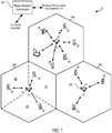
- a wireless communication system 10 includes base transceiver stations (BTSs) 12, disposed in cells 14, mobile access terminals 16 (ATs), and a base station controller (BSC) 18.
- the system 10 may support operation on multiple carriers (waveform signals of different frequencies).
- Multi-carrier transmitters can transmit modulated signals simultaneously on the multiple carriers.
- Each modulated signal may be a CDMA signal, a TDMA signal, an OFDMA signal, a SC-FDMA signal, etc.
- Each modulated signal may be sent on a different carrier and may carry pilot, overhead information, data, etc.
- the system 10 is a multi-carrier 1xEV-DO Rev. B network capable of efficiently allocating network resources.
- FIG. 1 shows the sectors 20 as being sharply defined, with the ATs being in only one sector 20 each, the sectors 20 overlap and a single AT 16 can be in multiple sectors 20 and multiple cells 14 simultaneously such that the BTSs 12 can communicate with the AT 16 through more than one sector 20 and more than one cell 14.
- the system 10 may include only macro base stations 12 or it can have base stations 12 of different types, e.g., macro, pico, and/or femto base stations.
- a macro base station may cover a relatively large geographic area (e.g., several kilometers in radius) and may allow unrestricted access by terminals with service subscription.
- a pico base station may cover a relatively small geographic area (e.g., a pico cell) and may allow unrestricted access by terminals with service subscription.
- a femto or home base station may cover a relatively small geographic area (e.g., a femto cell) and may allow restricted access by terminals having association with the femto cell (e.g., terminals for users in a home).
- the ATs 16 can be dispersed throughout the cells 14.
- the ATs 16 may be referred to as mobile stations, mobile devices, user equipment (UE), or subscriber units.
- the ATs 16 here include cellular phones and a wireless communication device, but can also include personal digital assistants (PDAs), other handheld devices, netbooks, notebook computers, etc.
- PDAs personal digital assistants
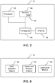
- an exemplary one of the ATs 16 comprises a computer system including a processor 40, memory 42, a transceiver 44, and an antenna 46.
- the transceiver 44 is configured to communicate bi-directionally with the BTS 12.
- the processor 40 is preferably an intelligent hardware device, e.g., a central processing unit (CPU) such as those made by Intel® Corporation or AMD®, a microcontroller, an application specific integrated circuit (ASIC), etc.
- the memory 42 includes random access memory (RAM) and read-only memory (ROM).
- the memory 42 stores computer-readable, computer-executable software code 43 containing instructions that are configured to, when executed, cause the processor 40 to perform various functions described herein.
- the software 43 may not be directly executable by the processor 40 but is configured to cause the computer, e.g., when compiled and executed, to perform the functions.
- the ATs 16 can communicate with the base stations 12 via forward and reverse links using an active set of carriers.
- the forward link (or downlink) refers to the communication link from the base station 12 to the terminal 16
- the reverse link (or uplink) refers to the communication link from the terminal 16 to the base station 12.
- the active set of carriers is the set of carriers for which communication with a base station 12 has been determined to be possible to a satisfactory degree.
- the active set can include sector-carrier pairs (pilots) corresponding to the base stations 12 that will decode transmissions from the AT 16 on the uplink and which can be selected by the AT 16 to receive downlink transmissions.
- soft-handoff terminals 16 select one sector for each carrier from the active set to receive downlink communications.
- each sector in a terminal's active set will attempt to decode its reverse link transmissions.
- the ATs 16 designate respective BTSs 12 for each of the carriers within the ATs' active sets of carriers. Each of the ATs 16 determines and selects, e.g., using a data rate control (DRC) signal, one of the BTSs 12 for each of its active set carriers. The selection is typically based upon which BTS 12 provides the best signal to interference-plus-noise ratio (SINR).
- DRC data rate control
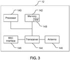
- an exemplary one of the BTSs 12 comprises a computer system including a processor 140, memory 142, a transceiver 144, an antenna 146, and a BSC interface 148.
- the transceiver 144 is configured to communicate bi-directionally with the ATs 16.
- the processor 140 is preferably an intelligent hardware device, e.g., a central processing unit (CPU) such as those made by Intel® Corporation or AMD®, a microcontroller, an application specific integrated circuit (ASIC), etc.
- the memory 142 includes random access memory (RAM) and read-only memory (ROM).
- the memory 142 stores computer-readable, computer-executable software code 143 containing instructions that are configured to, when executed, cause the processor 140 to perform various functions described herein.
- the software 143 may not be directly executable by the processor 140 but is configured to cause the computer, e.g., when compiled and executed, to perform the functions.
- the BTS 12 is connected and configured for bi-directional communication with the BSC 18. Typically, as here, the BSC 18 is hardwired to the BTSs 12.
- the BTS 12 is configured to convey, receive, encode, and decode transmissions to and from the BSC 18 using the transceiver 144 via the BSC interface 148.
- the BTS 12, through the processor 140 and the software code 143 implements, among other things, a scheduler to route data over pilots to the ATs 16 within the BTS's cell 14.
- the traffic load in the network 10 changes dynamically across the sectors and carriers as the ATs move and/or turn on/off applications.
- Data demand in the network 10 is intrinsically non-uniform, leading to chokepoint sectors or pilots and time variations so that which sectors or pilots are chokepoints change over time.
- a chokepoint sector operates at or close to a maximum tolerable or desired level for that sector 20. It has been found that typically there exists only a small portion of sectors 20 that are chokepoints at any given time and that chokepoint sectors typically have several lightly-loaded neighbor sectors. Neighbor sectors may not be adjacent physically, but are similar in a radio frequency (RF) sense as to the quality of communications available to a particular AT 16.
- RF radio frequency
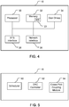
- the BSC 18 comprises a computer system including a processor 30, memory 32, disk drives 34, a network interface 36, and a BTS interface 38.
- the BTS interface 38 includes the transmitter and receiver for transmitting, receiving, encoding, and decoding transmissions between the BSC 18 and the BTSs 12.
- the processor 30 is preferably an intelligent hardware device, e.g., a central processing unit (CPU) such as those made by Intel® Corporation or AMD®, a microcontroller, an application specific integrated circuit (ASIC), etc.
- the memory 32 includes random access memory (RAM) and read-only memory (ROM).
- the disk drives 34 include a hard-disk drive and can include floppy-disk drives, a CD-ROM drive, and/or a zip drive.
- the network interface includes appropriate hardware for bi-directional communication to and from a mobile switch center (MSC) that is in communication with a phone network such as a public-switched telephone network (PSTN).
- MSC mobile switch center
- PSTN public-switched telephone network
- the BSC 18 is connected and configured for bi-directional communication with the BTSs 18.
- the BSC 18 is configured to convey, receive, encode, and decode transmissions to and from the BTSs 12 using the BTS interface 38 and the processor 30.
- the BSC 18 stores, e.g., in the memory 32, computer-readable, computer-executable software code 33 containing instructions that are configured to, when executed, cause the processor 30 to perform functions described below (although the description may read that the software 33 performs the function(s)).
- the software 33 may not be directly executable by the processor 30 but is configured to cause the computer, e.g., when compiled and executed, to perform the functions.
- the functions implement mechanisms for improving network performance through adapting network resources to network traffic load.
- the software 33 can be loaded onto the BSC 18, e.g., by being downloaded via a network connection, uploaded from a disk, etc.
- This is performed using a combination of distributed network scheduling at each BTS 12 and biasing flow control rates at the BSC 18 for sending data to multiple pilots serving an AT 16.
- each AT 16 may use information from the BSC 18 to send indications of poor link quality (null DRC in EV-DO systems) for inefficient pilots so that the AT 16 gets served on more efficient pilots.
- the BSC 18 includes a scheduler 50.
- the scheduler 50 is configured to determine and select the BTSs 12 to serve each of the ATs 16.
- the BSC 18 can cause multiple BTSs 12 to communicate with a single AT 16.
- the BTSs 12 will have uneven and perhaps less-than-desired loading, with some BTSs 12 being near capacity and other BTSs 12 being far from capacity.
- a process 70 of providing smart flow routing includes the stages shown.
- the process 70 is, however, exemplary only and not limiting.
- the process 70 can be altered, e.g., by having stages added, removed, or rearranged.
- the analysis and decisions described may be performed/made at the BSC 18, the ATs 16, or both the BSC 18 and the ATs 16.
- the BSC 18 controls which BTSs 12 serve which ATs 16 based on factors in addition to total load on the ATs 16.
- the scheduler 50 receives indicia regarding the ability to provide data to the ATs 16.
- the scheduler 50 receives data from which it can determine per-flow queue state, pilot service rate, AT channel state, loading level, quality of service (QoS) requirements of each flow, and spatial interference between pilots to help the scheduler 50 decide which pilots to use to serve the ATs 16 and at what data rates.
- the scheduler 50 receives feedback from the BTSs 12 as to the per-flow queue state of each pilot.
- the BSC 18 directly measures the service rates of each network flow in each pilot.
- the ATs 16 directly measure the AT channel states from each pilot and periodically send average AT channel state information to the BSC 18. This information includes indicia of forward link SINRs for respective pilots received at the ATs 16.
- these indicia of the received SINRs are the data rate control (DRC) signals.
- the BTSs 12 can filter the signals for the respective ATs 16 that the BTSs 12 serve and send the filtered information to the BSC 18, or each AT 16 can send the DRC signals to the BSC 18 directly.
- the BTSs 12 track the forward link data rate averaged over several seconds for each pilot for each AT 16 that the BTSs 12 serve. The BTSs 12 report these averages to the BSC 18.
- Neff s,c,t is the effective load for sector s, carrier c, at time t.
- Backhaul bandwidth limitations of the network 10 can also be included in the load measure.
- the spatial interference provides a measure of cross-coupling across pilots, and is discussed further below.
- the scheduler 50 determines a metric to bias the flow control rate across the pilots that serve respective ATs 16.
- the scheduler 50 uses the available data collected at stage 72 to decide which set of pilots and at what data rates to route packets for each flow in order to provide data to the ATs 16.
- the BSC 18 accounts for cross-pilot interference and load balancing by using pilot coupling (discussed further below) and flow service rate estimates.
- the scheduler 50 preferably uses all the available data to make its determination based on data rate expectations, both as to needs and availabilities.
- the scheduler 50 analyzes various options of data flow combinations and makes its decision as to which option to implement with a goal being to provide data to the ATs 16 efficiently, e.g., at the highest cumulative rate possible within the existing constraints, thus better utilizing available resources.
- An option may be analyzed by evaluating a whole option, or by evaluating a portion of the option that is different relative to another option.
- the scheduler 50 could, for example, decide to distribute incoming data proportional to the loading levels of the pilots, but a more efficient use will often be possible.
- the scheduler 50 for example, will likely route data from a first pilot to a second pilot that interferes little (or at least less than a third pilot) with the first pilot.
- Stage 74 is performed in conjunction with, and possibly concurrently with, stages 76 and 78 discussed below.
- the BSC 18 distributes data collected at stage 72 to the BTSs 12.
- the BSC 18 sends information to each pilot informing the pilot about its neighbor pilots.
- the neighbor pilots may be at different BTSs 12 and thus this mechanism uses the BSC 18 as a relay for passing information across pilots residing at distinct BTSs 12, given that the BTSs 12 do not communicate directly with each other.
- the BSC 18 conveys the average forward link data rate to each serving pilot for that AT 16.
- the BTSs 12 in a distributed manner use the information from the BSC 18 provided at stage 76 to further adjust data flow.
- Each BTS 12 computes a flow routing metric, or scheduler waiting, for each of the ATs 16 that the BTS 12 is serving for use in scheduling data flow to the ATs 16.
- w s , c , m , t is the scheduler weight for sector s, carrier c, for AT m, at time t
- d s , c , m , t and d s , c , m , t are the average an instantaneous forward link data rates for AT m, in sector s, on carrier c, at time t; r s , c , m ,
- the process 70 routes data flows away from heavily loaded pilots (chokepoints).
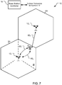
- the data are routed to flows that do not significantly interfere with the heavily loaded pilots, and the multiple paths are used in a highly efficient combination. For example, referring to FIG. 7 , suppose a BTS 12 1 serves an AT 16 at the cell edge with pilots 60 1 and 60 2 , and a BTS 12 2 serves the same AT 16 with another pilot 60 3 .
- the BSC 18 may instruct the BTS 12 1 to serve the AT 16 using the pilot 60 2 exclusively, or at least more heavily than the pilot 60 1 .
- the BSC 18 further determines that the pilot 60 3 has a lower SINR than either of the pilots 60 1 , 60 2 , but is so lightly loaded that the pilot 60 3 can provide better data rate despite its lower SINR, then the BSC 18 can direct the data through the BTS 12 2 instead of the BTS 12 1 .
- the example shown in FIG. 7 is for illustrative purposes.
- the BSC 18 can pass the raw information, e.g, loading, AT channel state, etc. to the BTS 12 and the BTS 12 can determine the efficient route for serving the ATs 16 in a distributed manner by using the information from the BSC 18.
- the cell 14b may be a chokepoint, as there are many ATs 16 being served.
- the process 70 can offload service from the BTS 12 in the cell 14b to a neighboring cell, for example by transferring ATs 16 at cell edges to neighboring sectors. Also, offloading sectors adjacent to chokepoint sectors reduces interference in the chokepoint sectors. Reducing load in chokepoint sectors can improve the chokepoint sector's capacity and improve the user's experience in that sector. This dynamic spatial isolation and dynamic flow routing can increase overall network capacity.
- the BTSs 12 can perform distributed network scheduling.
- the BTSs 12 can schedule data delivery to the ATs 16 in cooperation with other BTSs 12 instead of independently.
- the cooperation is distributed in that the cooperation is not centralized.
- the BTSs 12 periodically (e.g., every 2-3 seconds) convey their loading information to neighboring BTSs 12 through the BSC 18 as the BTSs 12 do not communicate directly with each other.
- the BTSs 12 send the loading levels and channel states for the ATs 16 that they are serving to the neighboring BTSs 12.
- the BTSs 12 can bias the scheduling weights for data delivery to their respective ATs 16.
- each BTS 12 can account for the service to a particular AT 16 from other BTSs 12 in addition to itself.
- smart flow routing includes two components.
- One component is the decision by the BSC 18 how to distribute data among available pilots for a given AT 16.
- the BSC 18 can also pass the raw information for this to the BTSs 12, and the BTSs 12 can use this to bias their flow control requests to the BSC 18.
- Another component is the BTSs 12 weighting the scheduling of data to the given AT 16 based on the channel state and loading level for each of the other pilots serving the given AT 16, including other pilots provided by one or more other BTSs 12. Network resource utilization can be improved on an average basis.
- Smart flow routing can be used in conjunction with other scheduler policies implemented for each pilot, and even if pilot schedulers are coordinating across carriers within a sector.
- the BSC 18 may use the BTS scheduler policies to determine expected flow service rates and to help decide how to relieve choke points.
- a process 110 of providing AT-controlled, BSC-assisted AT pointing includes the stages shown.
- the process 110 is, however, exemplary only and not limiting.
- the process 110 can be altered, e.g., by having stages added, removed, or rearranged.
- this information could be provided by the BTSs 12.
- the BSC 18 provides information for use by the ATs 16 in controlling which BTSs 12 the ATs 16 will select for service based on information in addition to SINR at the ATs 16.
- the ATs 16 work in conjunction with the BSC control of resource preference schemes at each BTS pilot scheduler discussed above with respect to FIG. 6 .
- the controller 52 sends information about pilot loading levels to the ATs 16.
- the controller 52 collects pilot loading information (stage 72 of FIG. 6 ) and broadcasts this information (using the BTS interface 38, FIG. 4 ) to the ATs 16. Additionally, the controller 52 sends a threshold value to be used by the ATs 16 to compare relative pilot strengths across pilots in each AT's active set. Typical threshold values are 3 dB or 4 dB.
- the non-legacy ATs 16 receive and decode the pilot loading information and the threshold value.
- the load level module 96 interprets the load level signal and the threshold value broadcast by the BSC 18 and provides this information to the pilot selection module 92.
- the module 92 uses the pilot load level information value to help determine which combination of pilots will provide a desirable (e.g., possibly optimal given the conditions) set of pilots for data flow.
- the pilot selection module 92 analyzes the information regarding load level and measured SINRs of forward link carriers. The module 92 determines which sector to use for each carrier by evaluating the tradeoff between (1) balancing pilot load and (2) partial loading performance and loss in serving pilot instantaneous signal quality similar to that discussed above.
- the pilot selection module 92 uses the threshold value to help determine the combination of pilots to use.
- the module 92 determines the relative pilot strengths of all the carriers in the AT's active set as compared to the pilot in the active set with the best strength. For any pilot whose relative strength is weaker than the best pilot strength by an amount greater than the threshold value sent by the BSC 18, and only any such pilots, the module 92 sends an indication of poor forward link quality to the BSC 18. In EV-DO systems, this indication is called a null DRC control signal. This signal indicates to the BTS 12 and the BSC 18 that the respective pilot is unacceptably poor and thus unavailable for use to communicate with the particular AT 16.
- the BTS 12 does not schedule an AT 16 on a forward link pilot for which the BTS 12 has received a null DRC for non-QoS traffic.
- the AT 16 can receive service only from a subset of pilots when there exists a large differential in pilot strength across the pilots in the AT's active set. Using this threshold value inhibits the AT 16 from eliminating pilots from use that have strengths close to the strongest pilot, and thus able to provide desirable data service.
- the BSC 18 further includes a cross-pilot coupling module 54.
- the module 54 is configured to analyze coupling between pilots and develop a topological spatial interference map 120 of pilot-to-pilot interference for use in smart-flow routing.
- the spatial-interference map 120 shows interference at pilots from neighbor pilots on the same channel, here the same CDMA channel.
- the neighbors are close in an RF or interference sense, even though they may be separated significantly in distance.
- BTSs 12a and 12b are neighbors, despite being physically separated by other cells 14.
- the map 120 is relatively static and changes due to long-term topology changes, e.g., new buildings, etc.
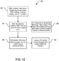
- a process 130 of developing the topological pilot-to-pilot interference map 120 includes the stages shown.
- the process 110 is, however, exemplary only and not limiting.
- the process 110 can be altered, e.g., by having stages added, removed, or rearranged. For example, stage 134 discussed below may be removed.
- the map 120 is shown and discussed, this is for illustrative purposes as different maps may be produced by the method 130.
- the process 130 is described as being performed by the BSC 18, but the process could be performed in a distributed manner by the BTSs 12, or offline, perhaps offsite from the network 10, and perhaps in a batch mode.
- data are collected and processed for use in preparing the map 120.
- ATs 16 near cell edges, they provide pilot strength information for handoff purposes, e.g., when forward link SINR falls below a threshold.
- the cross-pilot coupling module 54 tracks pilot strengths over time from pilot strength signals received from the ATs 16, in EV-DO the route update signals.
- the module 54 collects values of Ec/Io, i.e., the ratio of pilot signal energy to total received energy.
- the module 54 can use knowledge of pilot strength interplay (e.g., as strength in one sector weakens, the strength in another sector grows) to determine interference.
- the module 54 For each (serving sector-carrier, non-serving sector-carrier) pair reported by the ATs 16 (in the route update message), the module 54 generates an other-sector/serving-sector Ec ratio. For each non-serving sector-carrier not included in the information from the ATs 16, an Ec ratio of 0 is used for the serving sector.
- the module 54 averages the Ec ratios weighted by sector-carrier transmit power for a long time interval, e.g., several hours, greater than a day, greater than two days, about a week, etc.
- the module 54 thus develops estimates for relative pilot strength coupling, including directionality of the interference as indicated by arrows in the map 120.
- the map 120 provides average (e.g., over a week) interference indications.
- the strengths of the interference are indicated in the map 120 by solid lines (higher strength) and dashed lines (lower strength). Two interference strengths are shown for illustrative purposes, as the actual or relative strengths could be determined on
- the pilot-coupling module 54 gathers additional AT information.
- the module 54 gathers measured receive power and AT GPS location for a large number of representative AT locations within the cells 14.
- the module 54 processes this information to form a better estimate of pilot strength coupling and directionality.
- the module 54 stores the pilot coupling information developed at stages 132 and/or 134.
- the module 54 may not prepare the actual map 120, but does store the information from which such a map could be generated.
- the module 54 stores a value indicating interference magnitude for each servicing sector and non-serving sector pair.
- the stored value is, e.g., the average value of the Ec ratio as seen by ATs 16 served by the serving sector 20 averaged over the set of such reporting ATs 16.
- each BTS 12 computes this value for each serving sector-carrier using forward link signal strength information from the BSC 18 (e.g., from route update signals from the ATs 16).
- the cross-pilot coupling module 54 calculates interference metrics and provides its topological interference information to the scheduler 50.
- the module 54 determines an interference metric for each sector-carrier.
- the interference metric may be the sum, over all ATs 16 served by a sector-carrier, of the average Ec/Io of non-serving sector-carriers divided by the average Ec/Io of serving sector-carriers.
- the scheduler 50 uses this information to assist its determination of which pilots to use to serve the ATs 16, e.g., what data rates are available and which combination of pilots will improve, if not maximize, efficiency in the network 10.
- the cross-pilot coupling module 54 is configured to implement an adaptive reuse function to help adjust the resource preferences of the BTSs 12.
- the coupling module 54 distributes the topological interference map 120 information to the BTSs 12 so that they can determine preferred pilots for the ATs 16.
- the BTSs 12 use the interference information to reduce transmit power on capacity carriers (preferably not on coverage carriers) or to disable carriers completely.
- a BTS 12 may decide to reduce power by 3 dB, 6 dB, or to disable.
- the BTSs 12 do not reduce power more than 6 dB if the carrier is not to be disabled.
- the power reduction will apply for the pilot, MAC, and data portions of signals.
- the BTSs 12 are biased toward power reduction, preferring to disable carriers to the extent this is acceptable.
- the reuse function is distributed, with each BTS 12 determining when it should reduce transmit power or disable one or more sector-carriers.
- the sector-carrier power reductions and/or sector-carriers are reported to the BSC 18 for use in determining the flow routing, e.g., at stage 76 shown in FIG. 6 and discussed above.
- the ATs 16 can use pointing mechanisms such as DRC pointing control to enhance the ability of the BSC 18 to perform smart flow routing.
- ATs 16 choose the sector 20 with the highest forward link SINR for each carrier to be the serving sector 20 for that carrier, thus establishing the pilots (carrier-sector combinations).
- the BSC 18 influences the selection by the ATs 16, indicated by the DRC signals, by accounting for information in addition to SINR at the ATs 16 from which the BSC 18 can determine net resources that an AT 16 can receive.
- the BSC 18 uses more information, than traditional techniques, to try to determine an efficient use of network resources, preferably the best combination of resources to yield the best overall data rate given the system constraints. The result is that an AT 16 may be served by a pilot whose forward link SINR is worse than another available pilot, but whose loading is lighter.
- the BSC 18 further includes a controller 52 (in this EV-DO example, a DRC controller) configured to collect information in addition to SINR at the ATs 16.
- the controller 52 collects queue state information available from the scheduler 50 regarding flow control.
- the controller 52 can collect additional information including pilot loading information from the BTSs 12, information about current AT locations in the network in terms of channel quality to visible pilots, and/or position of the ATs 16. For example, information regarding pilot strength can be collected, with such information being contained in Route Update messages in DO systems.
- a controller 52 in this EV-DO example, a DRC controller
- each AT 16 includes a power and position module 94 that measures the power of received pilot signals periodically sends a message that contains (1) measured receive power from each pilot and (2) global positioning system (GPS) location of the AT 16.
- GPS global positioning system
- the controller 52 collects information about all of queue state, pilot loading, channel quality to visible pilots, and AT location. The controller 52 can broadcast the loading level of pilots to the ATs 16.
- This interference may be higher than for data traffic, especially as seen by a first sector if a second, neighboring, sector is lightly loaded.
- the interference induced by data traffic in the second sector on the first sector increases.
- the controller 52 thus controls the offloading of traffic while monitoring the changes in interference induced by doing so, and controls the traffic to inhibit the interference from increasing so much that the overall efficiency of the network decreases.
- the serving pilot instantaneous signal quality decreases because the controller 52 is causing an AT 16 to use a sector with a poorer SINR for a particular carrier and while lower SINR coupled with more time slots on the carrier may result in better data performance, the decrease in SINR is also monitored to inhibit decreases in overall network efficiency and to inhibit use of a SINR below an acceptable level.
- the BSC 18 is configured to provide AT DRC control for both non-legacy and legacy ATs 16.
- a non-legacy AT 16 includes a load level module 96 that can decode and interpret information in the broadcast message from the BSC 18 regarding loading level and bias the AT's sector selection, e.g., by biasing the measured SINRs using the loading information and selecting sectors using the biased SINRs.
- a legacy AT 16 cannot decode and understand the broadcast loading message from the BSC 18.
- the BSC 18 can select ATs 16 and force these ATs 16 to point to sectors 20 different from the sectors 20 that the ATs 16 would point to absent influence by the BSC 18.
- the controller 52 can send a DRC-lock signal to the legacy ATs 16 to control to which sectors the ATs 16 can point for a given carrier.
- the DRC-lock channel is a one-bit indication regarding the reverse link quality. If the DRC-lock is set to "unlock,” then the reverse link quality for the corresponding carrier-sector pair is poor, and thus unacceptable. If the DRC-lock is set to "lock,” then the reverse link quality (SINR) for the corresponding carrier-sector pair is good, and thus usable/reliable for decode purposes and acceptable for the AT 16 to point to this reverse link.
- Each of the ATs 16 includes a pilot selection module 92 configured to select carrier-sector pairs. Before the pilot selection module 92 selects a sector for a given carrier, the module 92 confirms that the reverse link quality for the instant carrier-sector pair is acceptable by analyzing the DRC-lock bit.
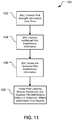
- a process 80 of providing AT DRC control includes the stages shown.
- the process 80 is, however, exemplary only and not limiting.
- the process 80 can be altered, e.g., by having stages added, removed, or rearranged.
- stages 82, 84, 86 are discussed as being implemented primarily by the BSC 18, these stages may be performed at the BSC 18, the ATs 16, or both the BSC 18 and the ATs 16.
- the BSC 18 controls which BTSs 12 the ATs 16 will select for service based on factors in addition to SINR at the ATs 16.
- the BSC 18 collects information to use in determining which pilots should be used by the ATs 16.
- the controller 52 collects information regarding queue state, pilot loading, channel quality of visible pilots, and AT locations.
- the BSC 18 broadcasts information for non-legacy ATs 16.
- the broadcast messages provide information about relative pilot loading levels of neighbor pilots.
- the BSC 18 periodically sends loading information (e.g., according to Equation (1), and possibly including backhaul bandwidth limitation effects) for each sector-carrier to all of its neighbor sector-carriers (i.e., to the BTSs 12 of the neighbor sector-carriers).
- the BTSs 12 collect the loading information into load messages that are broadcast periodically by the BTSs 12 on the control channel.
- the non-legacy ATs 16 receive the broadcast message from the BSC 18, interpret the message, and act upon it.
- the load level modules 96 of the non-legacy ATs 16 use the pilot loading information to bias the serving sector selections by the pilot selection module 92 by biasing the received SINRs based on the pilot loading.
- the module 92 chooses the sector providing the best biased SINR for each carrier.
- the result is BTS-assisted AT DRC repointing.
- the BTSs 12 send information to control sector selection by legacy ATs 16.
- the BTSs 12 analyze loading information (see stage 84) from each pilot, and the ATs' 16 pilot strength to each pilot in the ATs' 16 active sets. From this, the BTSs 12 determine which sectors the BTSs 12 do not want respective legacy ATs 16 to select for corresponding carriers, and send DRC-lock bits to indicate unlock for the reverse link for the respective sector-carrier pairs to the appropriate ATs 16.
- the legacy ATs 16 act upon the DRC-lock bits received from the controller 52.
- the pilot selection modules 92 of the legacy ATs 16 select the sector with the best SINR for a given carrier where the reverse link for that sector-carrier pair is locked. Note that while the pilot selection module 92 of FIG. 7 is referenced, this module differs between legacy and non-legacy ATs 16, and legacy ATs 16 will not include the load level module 96. The result is BTS-induced AT DRC repointing.
- AT pointing mechanisms can improve network efficiency.
- the efficiency can be improved even if less than all of the ATs 16 following balancing indications.
- having some ATs 16 follow the balancing indications can improve the overall network efficiency by more effectively using network resources.
- DSP digital signal processor
- ASIC application specific integrated circuit
- FPGA field programmable gate array
- a general-purpose processor may be a microprocessor, but in the alternative, the processor may be any conventional processor, controller, microcontroller, or state machine.
- a processor may also be implemented as a combination of computing devices, e.g., a combination of a DSP and a microprocessor, multiple microprocessors, one or more microprocessors in conjunction with a DSP core, or any other such configuration.
- a software module may reside in RAM memory, flash memory, ROM memory, EPROM memory, EEPROM memory, registers, hard disk, a removable disk, a CD-ROM, or any other form of storage medium known in the art.
- An exemplary storage medium is coupled to the processor such that the processor can read information from, and write information to, the storage medium.
- the storage medium may be integral to the processor.
- the processor and the storage medium may reside in an ASIC.
- the ASIC may reside in a user terminal.
- the processor and the storage medium may reside as discrete components in a user terminal.
- the functions described may be implemented in hardware, software executed by a processor, firmware, or any combination thereof. If implemented in software executed by a processor, the functions may be stored on or transmitted over as one or more instructions or code on a computer-readable medium.
- Computer-readable media includes both computer storage media and communication media including any medium that facilitates transfer of a computer program from one place to another.
- a storage medium may be any available medium that can be accessed by a general purpose or special purpose computer.
- computer-readable media can comprise RAM, ROM, EEPROM, CD-ROM or other optical disk storage, magnetic disk storage or other magnetic storage devices, or any other medium that can be used to carry or store desired program code means in the form of instructions or data structures and that can be accessed by a general-purpose or special-purpose computer, or a general-purpose or special-purpose processor. Also, any connection is properly termed a computer-readable medium.
- Disk and disc includes compact disc (CD), laser disc, optical disc, digital versatile disc (DVD), floppy disk and blu-ray disc where disks usually reproduce data magnetically, while discs reproduce data optically with lasers. Combinations of the above are also included within the scope of computer-readable media.
Landscapes
- Engineering & Computer Science (AREA)
- Computer Networks & Wireless Communication (AREA)
- Signal Processing (AREA)
- Quality & Reliability (AREA)
- Mobile Radio Communication Systems (AREA)
Applications Claiming Priority (4)
| Application Number | Priority Date | Filing Date | Title |
|---|---|---|---|
| US10833008P | 2008-10-24 | 2008-10-24 | |
| US12109008P | 2008-12-09 | 2008-12-09 | |
| US12/582,949 US8923125B2 (en) | 2008-10-24 | 2009-10-21 | Wireless network resource adaptation |
| PCT/US2009/061703 WO2010048419A2 (en) | 2008-10-24 | 2009-10-22 | Wireless network resource adaptation |
Publications (2)
| Publication Number | Publication Date |
|---|---|
| EP2351412A2 EP2351412A2 (en) | 2011-08-03 |
| EP2351412B1 true EP2351412B1 (en) | 2020-04-22 |
Family
ID=42026729
Family Applications (1)
| Application Number | Title | Priority Date | Filing Date |
|---|---|---|---|
| EP09748597.3A Active EP2351412B1 (en) | 2008-10-24 | 2009-10-22 | Wireless network resource adaptation |
Country Status (7)
| Country | Link |
|---|---|
| US (2) | US8923125B2 (enExample) |
| EP (1) | EP2351412B1 (enExample) |
| JP (3) | JP5551175B2 (enExample) |
| KR (3) | KR101389827B1 (enExample) |
| CN (1) | CN102187705B (enExample) |
| TW (1) | TWI454158B (enExample) |
| WO (1) | WO2010048419A2 (enExample) |
Families Citing this family (29)
| Publication number | Priority date | Publication date | Assignee | Title |
|---|---|---|---|---|
| JP5466034B2 (ja) * | 2010-02-15 | 2014-04-09 | 京セラ株式会社 | 無線基地局及び通信制御方法 |
| JP5440248B2 (ja) * | 2010-02-25 | 2014-03-12 | ソニー株式会社 | ハンドオーバを制御するための方法、端末装置、基地局及び無線通信システム |
| US8953444B2 (en) * | 2010-06-25 | 2015-02-10 | Qualcomm Incorporated | Load balancing |
| KR101761821B1 (ko) | 2010-07-29 | 2017-07-27 | 삼성전자주식회사 | 다중안테나 시스템에서 다중 섹터 협력 전송을 위한 송신 빔포밍과 다중 사용자 스케줄링 방법 및 장치 |
| GB2498311B (en) | 2010-10-28 | 2013-12-11 | Ibm | Method and system for transmitting data packets in a network |
| WO2012121656A1 (en) * | 2011-03-08 | 2012-09-13 | Telefonaktiebolaget L M Ericsson (Publ) | Methods and arrangements for handling carrier selection |
| US9769763B2 (en) * | 2011-04-26 | 2017-09-19 | Telefonaktiebolaget L M Ericsson | Nodes and method for power control |
| US9408223B2 (en) * | 2013-05-24 | 2016-08-02 | Sprint Spectrum L.P. | Systems and methods of managing frequency band selection |
| US10931721B2 (en) | 2013-12-27 | 2021-02-23 | T-Mobile Usa, Inc. | User account-based access to real-time communications |
| US20150188956A1 (en) | 2013-12-27 | 2015-07-02 | T-Mobile Usa, Inc. | Unified Communication Device |
| WO2016198112A1 (en) * | 2015-06-11 | 2016-12-15 | Telefonaktiebolaget Lm Ericsson (Publ) | Nodes and methods for handling packet flows |
| JP6955171B2 (ja) * | 2018-06-28 | 2021-10-27 | 日本電信電話株式会社 | 通信制御装置及び通信制御方法 |
| US10812216B2 (en) | 2018-11-05 | 2020-10-20 | XCOM Labs, Inc. | Cooperative multiple-input multiple-output downlink scheduling |
| US10659112B1 (en) | 2018-11-05 | 2020-05-19 | XCOM Labs, Inc. | User equipment assisted multiple-input multiple-output downlink configuration |
| US10756860B2 (en) | 2018-11-05 | 2020-08-25 | XCOM Labs, Inc. | Distributed multiple-input multiple-output downlink configuration |
| US10432272B1 (en) | 2018-11-05 | 2019-10-01 | XCOM Labs, Inc. | Variable multiple-input multiple-output downlink user equipment |
| KR20210087089A (ko) | 2018-11-27 | 2021-07-09 | 엑스콤 랩스 인코퍼레이티드 | 넌-코히어런트 협력 다중 입출력 통신 |
| US11063645B2 (en) | 2018-12-18 | 2021-07-13 | XCOM Labs, Inc. | Methods of wirelessly communicating with a group of devices |
| US10756795B2 (en) | 2018-12-18 | 2020-08-25 | XCOM Labs, Inc. | User equipment with cellular link and peer-to-peer link |
| US11330649B2 (en) | 2019-01-25 | 2022-05-10 | XCOM Labs, Inc. | Methods and systems of multi-link peer-to-peer communications |
| US10756767B1 (en) | 2019-02-05 | 2020-08-25 | XCOM Labs, Inc. | User equipment for wirelessly communicating cellular signal with another user equipment |
| US10911363B2 (en) | 2019-03-29 | 2021-02-02 | At&T Intellectual Property I, L.P. | Method and apparatus for performing file shaping |
| US10686502B1 (en) | 2019-04-29 | 2020-06-16 | XCOM Labs, Inc. | Downlink user equipment selection |
| US10735057B1 (en) | 2019-04-29 | 2020-08-04 | XCOM Labs, Inc. | Uplink user equipment selection |
| US11411778B2 (en) | 2019-07-12 | 2022-08-09 | XCOM Labs, Inc. | Time-division duplex multiple input multiple output calibration |
| US11902873B2 (en) * | 2019-10-25 | 2024-02-13 | Huawei Technologies Co., Ltd. | System, method and apparatus for managing network resources |
| US11411779B2 (en) | 2020-03-31 | 2022-08-09 | XCOM Labs, Inc. | Reference signal channel estimation |
| US12088499B2 (en) | 2020-04-15 | 2024-09-10 | Virewirx, Inc. | System and method for reducing data packet processing false alarms |
| WO2022241436A1 (en) | 2021-05-14 | 2022-11-17 | XCOM Labs, Inc. | Scrambling identifiers for wireless communication systems |
Family Cites Families (32)
| Publication number | Priority date | Publication date | Assignee | Title |
|---|---|---|---|---|
| US20030027250A1 (en) * | 1995-12-15 | 2003-02-06 | Mitchell Lloyd G. | Methods and compositions for use in spliceosome mediated RNA trans-splicing |
| ATE354957T1 (de) * | 1995-12-15 | 2006-03-15 | Intronn Inc | Durch trans-spaltung erhaltene therapeutische molekule |
| US6083702A (en) * | 1995-12-15 | 2000-07-04 | Intronn Holdings Llc | Methods and compositions for use in spliceosome mediated RNA trans-splicing |
| US6280978B1 (en) * | 1995-12-15 | 2001-08-28 | Intronn Holdings, Llc | Methods and compositions for use in spliceosome mediated RNA trans-splicing |
| US6434390B2 (en) | 1999-06-03 | 2002-08-13 | Lucent Technologies Inc. | Macrodiversity control system having macrodiversity mode based on operating category of wireless unit |
| US6563810B1 (en) * | 1999-09-30 | 2003-05-13 | Qualcomm Incorporated | Closed loop resource allocation |
| US7194280B2 (en) * | 2000-01-12 | 2007-03-20 | Telefonaktiebolaget Lm Ericsson (Publ) | Mobile station assisted forward link open loop power and rate control in a CDMA system |
| US6356767B2 (en) * | 2000-02-29 | 2002-03-12 | Motorola, Inc. | Method and apparatus for controlling mobile access to a wireless communication system |
| JP3821636B2 (ja) * | 2000-08-21 | 2006-09-13 | 松下電器産業株式会社 | 通信端末装置、基地局装置および無線通信方法 |
| US7099384B1 (en) | 2000-09-01 | 2006-08-29 | Qualcomm, Inc. | Method and apparatus for time-division power assignments in a wireless communication system |
| US6870808B1 (en) * | 2000-10-18 | 2005-03-22 | Adaptix, Inc. | Channel allocation in broadband orthogonal frequency-division multiple-access/space-division multiple-access networks |
| US6947748B2 (en) * | 2000-12-15 | 2005-09-20 | Adaptix, Inc. | OFDMA with adaptive subcarrier-cluster configuration and selective loading |
| US6842619B2 (en) * | 2001-07-19 | 2005-01-11 | Ericsson Inc. | Telecommunications system and method for load sharing within a code division multiple access 2000 network |
| GB0120033D0 (en) | 2001-08-16 | 2001-10-10 | Fujitsu Ltd | Cell selection |
| US20030204861A1 (en) * | 2002-04-30 | 2003-10-30 | Madaiah Puttaraju | Transgenic animal model for spliceosome-mediated RNA trans-splicing |
| US20050141446A1 (en) | 2002-05-31 | 2005-06-30 | Mitsubishi Denki Kabushiki Kaisha | Communication system |
| JP2007523509A (ja) | 2003-09-30 | 2007-08-16 | テレフオンアクチーボラゲット エル エム エリクソン(パブル) | 高速無線パケットデータネットワークにおける輻輳制御のための方法及び装置 |
| KR20060097720A (ko) | 2003-09-30 | 2006-09-14 | 텔레폰악티에볼라겟엘엠에릭슨(펍) | 고속 무선 패킷 데이터 네트워크 내의 혼잡 제어용 방법 및장치 |
| CN1860740A (zh) | 2003-09-30 | 2006-11-08 | 艾利森电话股份有限公司 | 用于高速无线分组数据网络中的拥塞控制的设备和方法 |
| ATE488068T1 (de) * | 2003-11-17 | 2010-11-15 | Quellan Inc | Verfahren und system zur löschung von antennenstörungen |
| US20050152320A1 (en) | 2004-01-08 | 2005-07-14 | Interdigital Technology Corporation | Wireless communication method and apparatus for balancing the loads of access points by controlling access point transmission power levels |
| EP1716165A4 (en) * | 2004-01-23 | 2008-06-18 | Virxsys Corp | EXPRESSION OF APOA-1 AND VARIANTS THEREOF, USING SPSSISSOSOM-MEDIATED RNA TRANS MIXING |
| US7968334B2 (en) * | 2004-01-23 | 2011-06-28 | Virxsys Corporation | Expression of apoAI and variants thereof using spliceosome mediated RNA trans-splicing |
| KR100800797B1 (ko) * | 2004-01-28 | 2008-02-04 | 삼성전자주식회사 | 통신 시스템에서 데이터 송수신 방법 |
| US20060134658A1 (en) * | 2004-08-09 | 2006-06-22 | Garcia-Blanco Mariano A | Use of RNA trans-splicing for generation of interfering RNA molecules |
| US7680093B2 (en) * | 2004-08-27 | 2010-03-16 | Telefonaktiebolaget Lm Ericsson (Publ) | Sector selection for F-SCH |
| EP1831365B1 (en) * | 2004-10-08 | 2013-08-07 | VIRxSYS Corporation | Use of rna trans-splicing for antibody gene transfer and antibody polypeptide production |
| US8027306B2 (en) | 2006-02-17 | 2011-09-27 | Lg Electronics Inc. | Miscellaneous improvements on the HRPD system |
| JPWO2008004299A1 (ja) * | 2006-07-06 | 2009-12-03 | 富士通株式会社 | 無線通信システム、基地局装置及び移動局装置 |
| JP2008042736A (ja) | 2006-08-09 | 2008-02-21 | Kddi Corp | セル重複検出装置、制御局装置、移動局装置及び無線通信制御方法 |
| US8160629B2 (en) * | 2006-09-07 | 2012-04-17 | Airvana, Corp. | Controlling reverse link interference in private access points for wireless networking |
| RU2485180C2 (ru) * | 2007-06-07 | 2013-06-20 | Эгрикалча Энд Эгри-Фуд Кэнэда | Способ трансфекции и трансдукции растительных клеток |
-
2009
- 2009-10-21 US US12/582,949 patent/US8923125B2/en active Active
- 2009-10-22 EP EP09748597.3A patent/EP2351412B1/en active Active
- 2009-10-22 US US13/121,399 patent/US20110235515A1/en not_active Abandoned
- 2009-10-22 KR KR1020117011792A patent/KR101389827B1/ko not_active Expired - Fee Related
- 2009-10-22 KR KR1020137011093A patent/KR101426889B1/ko active Active
- 2009-10-22 JP JP2011533339A patent/JP5551175B2/ja not_active Expired - Fee Related
- 2009-10-22 KR KR1020137035062A patent/KR101477567B1/ko not_active Expired - Fee Related
- 2009-10-22 CN CN200980142157.5A patent/CN102187705B/zh active Active
- 2009-10-22 WO PCT/US2009/061703 patent/WO2010048419A2/en not_active Ceased
- 2009-10-26 TW TW098136219A patent/TWI454158B/zh not_active IP Right Cessation
-
2013
- 2013-07-01 JP JP2013138127A patent/JP2013258709A/ja not_active Withdrawn
-
2015
- 2015-06-10 JP JP2015117552A patent/JP5960326B2/ja not_active Expired - Fee Related
Non-Patent Citations (1)
| Title |
|---|
| None * |
Also Published As
| Publication number | Publication date |
|---|---|
| JP2013258709A (ja) | 2013-12-26 |
| WO2010048419A2 (en) | 2010-04-29 |
| JP5551175B2 (ja) | 2014-07-16 |
| CN102187705A (zh) | 2011-09-14 |
| KR20130054454A (ko) | 2013-05-24 |
| JP2012507196A (ja) | 2012-03-22 |
| US20110235515A1 (en) | 2011-09-29 |
| JP2015216643A (ja) | 2015-12-03 |
| KR101426889B1 (ko) | 2014-08-05 |
| TWI454158B (zh) | 2014-09-21 |
| KR101389827B1 (ko) | 2014-05-13 |
| CN102187705B (zh) | 2015-07-08 |
| US8923125B2 (en) | 2014-12-30 |
| KR101477567B1 (ko) | 2014-12-30 |
| EP2351412A2 (en) | 2011-08-03 |
| US20100165845A1 (en) | 2010-07-01 |
| JP5960326B2 (ja) | 2016-08-02 |
| KR20140009594A (ko) | 2014-01-22 |
| KR20110074928A (ko) | 2011-07-04 |
| TW201032619A (en) | 2010-09-01 |
| WO2010048419A3 (en) | 2010-06-24 |
Similar Documents
| Publication | Publication Date | Title |
|---|---|---|
| EP2351412B1 (en) | Wireless network resource adaptation | |
| US9258743B2 (en) | Resource scaling in wireless communication systems | |
| US11569948B2 (en) | Wireless communication system, wireless communication method, radio station and program | |
| US9826409B2 (en) | Adaptive semi-static interference avoidance in cellular networks | |
| EP2761797B1 (en) | Methods and apparatus for interference management | |
| US7953417B2 (en) | Methods and apparatus for selecting and signaling a preferred link among a plurality of maintained wireless communications links | |
| US8385832B2 (en) | Inter-cell interference control in an uplink multi-carrier radio communications system | |
| AU2008350272B2 (en) | Sector interference management based on inter-sector performance | |
| JP2010525698A (ja) | 通信ネットワークにおいてセル間干渉を管理するための方法及び装置 | |
| WO2009025731A1 (en) | Method for selecting a serving carrier in a multi-carrier system | |
| WO2012099520A1 (en) | Methods and devices for multipoint transmission | |
| US20170215195A1 (en) | Radio Resource Management in Multi-Vendor Inter-eNB Carrier Aggregation | |
| WO2017045695A1 (en) | Method, system and apparatus for switching between d2d and cellular communications | |
| EP2835923B1 (en) | User equipment and method to report CQI when interference cancellation is supported at the receiver | |
| EP1958382B1 (en) | Methods and apparatus for selecting and signaling a preferred link among a plurality of maintained wireless communications links | |
| EP3167563B1 (en) | Carrier aggregation mode selection |
Legal Events
| Date | Code | Title | Description |
|---|---|---|---|
| PUAI | Public reference made under article 153(3) epc to a published international application that has entered the european phase |
Free format text: ORIGINAL CODE: 0009012 |
|
| 17P | Request for examination filed |
Effective date: 20110524 |
|
| AK | Designated contracting states |
Kind code of ref document: A2 Designated state(s): AT BE BG CH CY CZ DE DK EE ES FI FR GB GR HR HU IE IS IT LI LT LU LV MC MK MT NL NO PL PT RO SE SI SK SM TR |
|
| DAX | Request for extension of the european patent (deleted) | ||
| 17Q | First examination report despatched |
Effective date: 20120411 |
|
| STAA | Information on the status of an ep patent application or granted ep patent |
Free format text: STATUS: EXAMINATION IS IN PROGRESS |
|
| RIC1 | Information provided on ipc code assigned before grant |
Ipc: H04W 72/04 20090101ALN20190919BHEP Ipc: H04W 72/00 20090101ALN20190919BHEP Ipc: H04W 48/16 20090101ALN20190919BHEP Ipc: H04L 12/801 20130101ALI20190919BHEP Ipc: H04W 28/08 20090101AFI20190919BHEP |
|
| GRAP | Despatch of communication of intention to grant a patent |
Free format text: ORIGINAL CODE: EPIDOSNIGR1 |
|
| STAA | Information on the status of an ep patent application or granted ep patent |
Free format text: STATUS: GRANT OF PATENT IS INTENDED |
|
| RIC1 | Information provided on ipc code assigned before grant |
Ipc: H04L 12/801 20130101ALI20191030BHEP Ipc: H04W 28/08 20090101AFI20191030BHEP Ipc: H04W 48/16 20090101ALN20191030BHEP Ipc: H04W 72/00 20090101ALN20191030BHEP Ipc: H04W 72/04 20090101ALN20191030BHEP |
|
| INTG | Intention to grant announced |
Effective date: 20191113 |
|
| GRAS | Grant fee paid |
Free format text: ORIGINAL CODE: EPIDOSNIGR3 |
|
| GRAA | (expected) grant |
Free format text: ORIGINAL CODE: 0009210 |
|
| STAA | Information on the status of an ep patent application or granted ep patent |
Free format text: STATUS: THE PATENT HAS BEEN GRANTED |
|
| AK | Designated contracting states |
Kind code of ref document: B1 Designated state(s): AT BE BG CH CY CZ DE DK EE ES FI FR GB GR HR HU IE IS IT LI LT LU LV MC MK MT NL NO PL PT RO SE SI SK SM TR |
|
| REG | Reference to a national code |
Ref country code: GB Ref legal event code: FG4D |
|
| REG | Reference to a national code |
Ref country code: CH Ref legal event code: EP |
|
| REG | Reference to a national code |
Ref country code: DE Ref legal event code: R096 Ref document number: 602009061789 Country of ref document: DE |
|
| REG | Reference to a national code |
Ref country code: IE Ref legal event code: FG4D |
|
| REG | Reference to a national code |
Ref country code: AT Ref legal event code: REF Ref document number: 1261800 Country of ref document: AT Kind code of ref document: T Effective date: 20200515 |
|
| REG | Reference to a national code |
Ref country code: LT Ref legal event code: MG4D |
|
| REG | Reference to a national code |
Ref country code: NL Ref legal event code: MP Effective date: 20200422 |
|
| PG25 | Lapsed in a contracting state [announced via postgrant information from national office to epo] |
Ref country code: NL Free format text: LAPSE BECAUSE OF FAILURE TO SUBMIT A TRANSLATION OF THE DESCRIPTION OR TO PAY THE FEE WITHIN THE PRESCRIBED TIME-LIMIT Effective date: 20200422 Ref country code: SE Free format text: LAPSE BECAUSE OF FAILURE TO SUBMIT A TRANSLATION OF THE DESCRIPTION OR TO PAY THE FEE WITHIN THE PRESCRIBED TIME-LIMIT Effective date: 20200422 Ref country code: LT Free format text: LAPSE BECAUSE OF FAILURE TO SUBMIT A TRANSLATION OF THE DESCRIPTION OR TO PAY THE FEE WITHIN THE PRESCRIBED TIME-LIMIT Effective date: 20200422 Ref country code: PT Free format text: LAPSE BECAUSE OF FAILURE TO SUBMIT A TRANSLATION OF THE DESCRIPTION OR TO PAY THE FEE WITHIN THE PRESCRIBED TIME-LIMIT Effective date: 20200824 Ref country code: IS Free format text: LAPSE BECAUSE OF FAILURE TO SUBMIT A TRANSLATION OF THE DESCRIPTION OR TO PAY THE FEE WITHIN THE PRESCRIBED TIME-LIMIT Effective date: 20200822 Ref country code: NO Free format text: LAPSE BECAUSE OF FAILURE TO SUBMIT A TRANSLATION OF THE DESCRIPTION OR TO PAY THE FEE WITHIN THE PRESCRIBED TIME-LIMIT Effective date: 20200722 Ref country code: GR Free format text: LAPSE BECAUSE OF FAILURE TO SUBMIT A TRANSLATION OF THE DESCRIPTION OR TO PAY THE FEE WITHIN THE PRESCRIBED TIME-LIMIT Effective date: 20200723 Ref country code: FI Free format text: LAPSE BECAUSE OF FAILURE TO SUBMIT A TRANSLATION OF THE DESCRIPTION OR TO PAY THE FEE WITHIN THE PRESCRIBED TIME-LIMIT Effective date: 20200422 |
|
| PGFP | Annual fee paid to national office [announced via postgrant information from national office to epo] |
Ref country code: GB Payment date: 20200803 Year of fee payment: 12 |
|
| REG | Reference to a national code |
Ref country code: AT Ref legal event code: MK05 Ref document number: 1261800 Country of ref document: AT Kind code of ref document: T Effective date: 20200422 |
|
| PG25 | Lapsed in a contracting state [announced via postgrant information from national office to epo] |
Ref country code: LV Free format text: LAPSE BECAUSE OF FAILURE TO SUBMIT A TRANSLATION OF THE DESCRIPTION OR TO PAY THE FEE WITHIN THE PRESCRIBED TIME-LIMIT Effective date: 20200422 Ref country code: HR Free format text: LAPSE BECAUSE OF FAILURE TO SUBMIT A TRANSLATION OF THE DESCRIPTION OR TO PAY THE FEE WITHIN THE PRESCRIBED TIME-LIMIT Effective date: 20200422 Ref country code: BG Free format text: LAPSE BECAUSE OF FAILURE TO SUBMIT A TRANSLATION OF THE DESCRIPTION OR TO PAY THE FEE WITHIN THE PRESCRIBED TIME-LIMIT Effective date: 20200722 |
|
| REG | Reference to a national code |
Ref country code: DE Ref legal event code: R097 Ref document number: 602009061789 Country of ref document: DE |
|
| PG25 | Lapsed in a contracting state [announced via postgrant information from national office to epo] |
Ref country code: IT Free format text: LAPSE BECAUSE OF FAILURE TO SUBMIT A TRANSLATION OF THE DESCRIPTION OR TO PAY THE FEE WITHIN THE PRESCRIBED TIME-LIMIT Effective date: 20200422 Ref country code: CZ Free format text: LAPSE BECAUSE OF FAILURE TO SUBMIT A TRANSLATION OF THE DESCRIPTION OR TO PAY THE FEE WITHIN THE PRESCRIBED TIME-LIMIT Effective date: 20200422 Ref country code: RO Free format text: LAPSE BECAUSE OF FAILURE TO SUBMIT A TRANSLATION OF THE DESCRIPTION OR TO PAY THE FEE WITHIN THE PRESCRIBED TIME-LIMIT Effective date: 20200422 Ref country code: ES Free format text: LAPSE BECAUSE OF FAILURE TO SUBMIT A TRANSLATION OF THE DESCRIPTION OR TO PAY THE FEE WITHIN THE PRESCRIBED TIME-LIMIT Effective date: 20200422 Ref country code: AT Free format text: LAPSE BECAUSE OF FAILURE TO SUBMIT A TRANSLATION OF THE DESCRIPTION OR TO PAY THE FEE WITHIN THE PRESCRIBED TIME-LIMIT Effective date: 20200422 Ref country code: DK Free format text: LAPSE BECAUSE OF FAILURE TO SUBMIT A TRANSLATION OF THE DESCRIPTION OR TO PAY THE FEE WITHIN THE PRESCRIBED TIME-LIMIT Effective date: 20200422 Ref country code: EE Free format text: LAPSE BECAUSE OF FAILURE TO SUBMIT A TRANSLATION OF THE DESCRIPTION OR TO PAY THE FEE WITHIN THE PRESCRIBED TIME-LIMIT Effective date: 20200422 Ref country code: SM Free format text: LAPSE BECAUSE OF FAILURE TO SUBMIT A TRANSLATION OF THE DESCRIPTION OR TO PAY THE FEE WITHIN THE PRESCRIBED TIME-LIMIT Effective date: 20200422 |
|
| PGFP | Annual fee paid to national office [announced via postgrant information from national office to epo] |
Ref country code: DE Payment date: 20200409 Year of fee payment: 12 |
|
| PG25 | Lapsed in a contracting state [announced via postgrant information from national office to epo] |
Ref country code: SK Free format text: LAPSE BECAUSE OF FAILURE TO SUBMIT A TRANSLATION OF THE DESCRIPTION OR TO PAY THE FEE WITHIN THE PRESCRIBED TIME-LIMIT Effective date: 20200422 Ref country code: PL Free format text: LAPSE BECAUSE OF FAILURE TO SUBMIT A TRANSLATION OF THE DESCRIPTION OR TO PAY THE FEE WITHIN THE PRESCRIBED TIME-LIMIT Effective date: 20200422 |
|
| PLBE | No opposition filed within time limit |
Free format text: ORIGINAL CODE: 0009261 |
|
| STAA | Information on the status of an ep patent application or granted ep patent |
Free format text: STATUS: NO OPPOSITION FILED WITHIN TIME LIMIT |
|
| 26N | No opposition filed |
Effective date: 20210125 |
|
| PG25 | Lapsed in a contracting state [announced via postgrant information from national office to epo] |
Ref country code: SI Free format text: LAPSE BECAUSE OF FAILURE TO SUBMIT A TRANSLATION OF THE DESCRIPTION OR TO PAY THE FEE WITHIN THE PRESCRIBED TIME-LIMIT Effective date: 20200422 |
|
| REG | Reference to a national code |
Ref country code: CH Ref legal event code: PL |
|
| PG25 | Lapsed in a contracting state [announced via postgrant information from national office to epo] |
Ref country code: LU Free format text: LAPSE BECAUSE OF NON-PAYMENT OF DUE FEES Effective date: 20201022 Ref country code: MC Free format text: LAPSE BECAUSE OF FAILURE TO SUBMIT A TRANSLATION OF THE DESCRIPTION OR TO PAY THE FEE WITHIN THE PRESCRIBED TIME-LIMIT Effective date: 20200422 |
|
| REG | Reference to a national code |
Ref country code: BE Ref legal event code: MM Effective date: 20201031 |
|
| PG25 | Lapsed in a contracting state [announced via postgrant information from national office to epo] |
Ref country code: FR Free format text: LAPSE BECAUSE OF NON-PAYMENT OF DUE FEES Effective date: 20201031 |
|
| PG25 | Lapsed in a contracting state [announced via postgrant information from national office to epo] |
Ref country code: LI Free format text: LAPSE BECAUSE OF NON-PAYMENT OF DUE FEES Effective date: 20201031 Ref country code: BE Free format text: LAPSE BECAUSE OF NON-PAYMENT OF DUE FEES Effective date: 20201031 Ref country code: CH Free format text: LAPSE BECAUSE OF NON-PAYMENT OF DUE FEES Effective date: 20201031 |
|
| PG25 | Lapsed in a contracting state [announced via postgrant information from national office to epo] |
Ref country code: IE Free format text: LAPSE BECAUSE OF NON-PAYMENT OF DUE FEES Effective date: 20201022 |
|
| REG | Reference to a national code |
Ref country code: DE Ref legal event code: R119 Ref document number: 602009061789 Country of ref document: DE |
|
| PG25 | Lapsed in a contracting state [announced via postgrant information from national office to epo] |
Ref country code: TR Free format text: LAPSE BECAUSE OF FAILURE TO SUBMIT A TRANSLATION OF THE DESCRIPTION OR TO PAY THE FEE WITHIN THE PRESCRIBED TIME-LIMIT Effective date: 20200422 Ref country code: MT Free format text: LAPSE BECAUSE OF FAILURE TO SUBMIT A TRANSLATION OF THE DESCRIPTION OR TO PAY THE FEE WITHIN THE PRESCRIBED TIME-LIMIT Effective date: 20200422 Ref country code: CY Free format text: LAPSE BECAUSE OF FAILURE TO SUBMIT A TRANSLATION OF THE DESCRIPTION OR TO PAY THE FEE WITHIN THE PRESCRIBED TIME-LIMIT Effective date: 20200422 |
|
| GBPC | Gb: european patent ceased through non-payment of renewal fee |
Effective date: 20211022 |
|
| PG25 | Lapsed in a contracting state [announced via postgrant information from national office to epo] |
Ref country code: MK Free format text: LAPSE BECAUSE OF FAILURE TO SUBMIT A TRANSLATION OF THE DESCRIPTION OR TO PAY THE FEE WITHIN THE PRESCRIBED TIME-LIMIT Effective date: 20200422 |
|
| PG25 | Lapsed in a contracting state [announced via postgrant information from national office to epo] |
Ref country code: GB Free format text: LAPSE BECAUSE OF NON-PAYMENT OF DUE FEES Effective date: 20211022 Ref country code: DE Free format text: LAPSE BECAUSE OF NON-PAYMENT OF DUE FEES Effective date: 20220503 |