EP2350565B1 - Einrichtung und verfahren zum bestimmen eines charakteristikums eines durch aufeinanderfolgende positionen eines starr mit einem mobilen element verbundenen triaxialbeschleunigungsmessers gebildeten pfads - Google Patents
Einrichtung und verfahren zum bestimmen eines charakteristikums eines durch aufeinanderfolgende positionen eines starr mit einem mobilen element verbundenen triaxialbeschleunigungsmessers gebildeten pfads Download PDFInfo
- Publication number
- EP2350565B1 EP2350565B1 EP09736970.6A EP09736970A EP2350565B1 EP 2350565 B1 EP2350565 B1 EP 2350565B1 EP 09736970 A EP09736970 A EP 09736970A EP 2350565 B1 EP2350565 B1 EP 2350565B1
- Authority
- EP
- European Patent Office
- Prior art keywords
- triaxial accelerometer
- reference point
- triaxial
- immobility
- vector
- Prior art date
- Legal status (The legal status is an assumption and is not a legal conclusion. Google has not performed a legal analysis and makes no representation as to the accuracy of the status listed.)
- Active
Links
- 238000000034 method Methods 0.000 title claims description 13
- 239000013598 vector Substances 0.000 claims description 134
- 238000004364 calculation method Methods 0.000 claims description 58
- 239000011159 matrix material Substances 0.000 claims description 25
- 230000001133 acceleration Effects 0.000 claims description 22
- 230000033001 locomotion Effects 0.000 claims description 11
- 238000004458 analytical method Methods 0.000 claims description 4
- 101100129915 Escherichia coli (strain K12) melB gene Proteins 0.000 claims description 2
- 102100024594 Histone-lysine N-methyltransferase PRDM16 Human genes 0.000 claims description 2
- 101000686942 Homo sapiens Histone-lysine N-methyltransferase PRDM16 Proteins 0.000 claims description 2
- 230000000007 visual effect Effects 0.000 claims description 2
- 230000015556 catabolic process Effects 0.000 claims 3
- 238000005259 measurement Methods 0.000 description 23
- 238000006073 displacement reaction Methods 0.000 description 21
- 239000003550 marker Substances 0.000 description 10
- 230000002829 reductive effect Effects 0.000 description 9
- 238000012550 audit Methods 0.000 description 7
- 230000010354 integration Effects 0.000 description 7
- 101100401000 Saccharomyces cerevisiae MEL2 gene Proteins 0.000 description 6
- 238000000354 decomposition reaction Methods 0.000 description 6
- 238000011161 development Methods 0.000 description 6
- 230000005484 gravity Effects 0.000 description 4
- 241001465754 Metazoa Species 0.000 description 3
- 230000001419 dependent effect Effects 0.000 description 3
- 229940079593 drug Drugs 0.000 description 2
- 239000003814 drug Substances 0.000 description 2
- 238000011156 evaluation Methods 0.000 description 2
- 230000005021 gait Effects 0.000 description 2
- 238000004519 manufacturing process Methods 0.000 description 2
- 238000012544 monitoring process Methods 0.000 description 2
- 238000005070 sampling Methods 0.000 description 2
- 238000013519 translation Methods 0.000 description 2
- 238000007792 addition Methods 0.000 description 1
- 238000013459 approach Methods 0.000 description 1
- 230000003190 augmentative effect Effects 0.000 description 1
- 230000005540 biological transmission Effects 0.000 description 1
- 230000000903 blocking effect Effects 0.000 description 1
- 238000004891 communication Methods 0.000 description 1
- 230000003247 decreasing effect Effects 0.000 description 1
- 238000001514 detection method Methods 0.000 description 1
- 238000003745 diagnosis Methods 0.000 description 1
- 230000006870 function Effects 0.000 description 1
- 230000004927 fusion Effects 0.000 description 1
- 230000002452 interceptive effect Effects 0.000 description 1
- 230000000670 limiting effect Effects 0.000 description 1
- 230000004807 localization Effects 0.000 description 1
- 238000013507 mapping Methods 0.000 description 1
- 230000037230 mobility Effects 0.000 description 1
- 230000003287 optical effect Effects 0.000 description 1
- 230000001144 postural effect Effects 0.000 description 1
- 230000000135 prohibitive effect Effects 0.000 description 1
- 238000007619 statistical method Methods 0.000 description 1
- 230000002123 temporal effect Effects 0.000 description 1
- 230000009466 transformation Effects 0.000 description 1
- 238000002604 ultrasonography Methods 0.000 description 1
Images

Classifications
-
- G—PHYSICS
- G01—MEASURING; TESTING
- G01C—MEASURING DISTANCES, LEVELS OR BEARINGS; SURVEYING; NAVIGATION; GYROSCOPIC INSTRUMENTS; PHOTOGRAMMETRY OR VIDEOGRAMMETRY
- G01C22/00—Measuring distance traversed on the ground by vehicles, persons, animals or other moving solid bodies, e.g. using odometers, using pedometers
- G01C22/006—Pedometers
-
- G—PHYSICS
- G01—MEASURING; TESTING
- G01C—MEASURING DISTANCES, LEVELS OR BEARINGS; SURVEYING; NAVIGATION; GYROSCOPIC INSTRUMENTS; PHOTOGRAMMETRY OR VIDEOGRAMMETRY
- G01C21/00—Navigation; Navigational instruments not provided for in groups G01C1/00 - G01C19/00
- G01C21/10—Navigation; Navigational instruments not provided for in groups G01C1/00 - G01C19/00 by using measurements of speed or acceleration
- G01C21/12—Navigation; Navigational instruments not provided for in groups G01C1/00 - G01C19/00 by using measurements of speed or acceleration executed aboard the object being navigated; Dead reckoning
- G01C21/16—Navigation; Navigational instruments not provided for in groups G01C1/00 - G01C19/00 by using measurements of speed or acceleration executed aboard the object being navigated; Dead reckoning by integrating acceleration or speed, i.e. inertial navigation
- G01C21/165—Navigation; Navigational instruments not provided for in groups G01C1/00 - G01C19/00 by using measurements of speed or acceleration executed aboard the object being navigated; Dead reckoning by integrating acceleration or speed, i.e. inertial navigation combined with non-inertial navigation instruments
- G01C21/1654—Navigation; Navigational instruments not provided for in groups G01C1/00 - G01C19/00 by using measurements of speed or acceleration executed aboard the object being navigated; Dead reckoning by integrating acceleration or speed, i.e. inertial navigation combined with non-inertial navigation instruments with electromagnetic compass
-
- G—PHYSICS
- G01—MEASURING; TESTING
- G01P—MEASURING LINEAR OR ANGULAR SPEED, ACCELERATION, DECELERATION, OR SHOCK; INDICATING PRESENCE, ABSENCE, OR DIRECTION, OF MOVEMENT
- G01P15/00—Measuring acceleration; Measuring deceleration; Measuring shock, i.e. sudden change of acceleration
- G01P15/18—Measuring acceleration; Measuring deceleration; Measuring shock, i.e. sudden change of acceleration in two or more dimensions
Definitions
- the invention relates to a device for determining a characteristic of a trajectory formed of successive positions of a triaxial accelerometer linked to a movable element.
- Motion capture is for consumer applications such as entertainment applications (interactive game consoles, sports gesture tracking, virtual reality or augmented reality), pedestrian navigation assistance applications (most used at the time). currently being satellite navigation systems such as GPS), applications to help the mobility of vulnerable or temporarily weakened by their environment (disabled or dark), and fitness applications (pedometer, calculation energy expenditure or distance traveled).
- entertainment applications interactive game consoles, sports gesture tracking, virtual reality or augmented reality
- pedestrian navigation assistance applications most used at the time.
- satellite navigation systems such as GPS
- applications to help the mobility of vulnerable or temporarily weakened by their environment disabled or dark
- fitness applications pedometer, calculation energy expenditure or distance traveled.
- Motion capture also concerns medical applications (monitoring of the elderly and / or dependent, gait analysis for postural rehabilitation or assistance with diagnosis), safety or emergency applications (location of firefighters inside a building on fire, operational monitoring of soldiers, or surveillance of prisoners), but also commercial applications (statistics on trajectories followed by consumers in shopping centers or supermarkets, definition of archetypes of use, or proposal topo-dependent commercial services).
- attitude sensors accelerelerometer (s), magnetometer (s), gyrometer
- attitude sensors most often delivering inertial measurements.
- attitude sensors accelerelerometer (s), magnetometer (s), gyrometer
- Inertial head-tracker sensor fusion by a separate-biased kalman filter (E. Foxlin) published in March 1996 in Virtual Reality Annual International Symposium, Proceedings of the IEEE 1996, pages 185-194 ; " (Kogure L. Seon-Woo K. and K. Mase), published in 2005 in Engineering in Medicine and Biology Society, IEEE-EMBS 2005.
- Video game consoles such as the Wii, use optical and / or ultrasound sensors to determine the trajectory of a game control element. These systems are expensive and limited.
- the acceleration is integrated in the axis of the foot.
- These systems have a reduced cost, but have other disadvantages.
- the sensors are perfectly placed in the sagittal plane, which is almost impossible to achieve concretely by the user, and causes an estimation error related to the poor positioning of the sensor or sensors.
- walking occurs in the sagittal plane, which may not be the case, when walking on the side, for example.
- This system has a reduced cost of replacing a single-axis gyrometer by a pair of accelerometers compared to systems with gyrometers proposed by Alvarez et al and Scapellato and al.
- a system has the same disadvantages as the example cited above, because only the rotation about the orthogonal axis to the sagittal plane is taken into account.
- the estimation of the rotation by a pair of accelerometers like that made using a gyrometer, has significant drift.
- a heading is also determined using a magnetometer, for example when the foot is placed, which gives the direction of the foot and not the direction of the desired movement.
- the device JP2008116315 discloses determining a substantially invariant axis of rotation (or equivalently, the plane orthogonal to said axis) of the triaxial accelerometer from the vectors delivered by the triaxial accelerometer. This determination takes place between two instants of immobility, including two consecutive instants. On the other hand, the projection (see the use for the calculations) of the vectors delivered by the additional sensor (eg magnetometer) is not carried out at said successive times.
- the device JP2008116315 first performs a statistical analysis of vectors delivered by the accelerometer during a certain number of immobility times (equal to all the times during which the GPS sensor does not receive signals). The result of this analysis is the determination of the invariant orthogonal plane, from which the direction of the trajectory is obtained. The vectors delivered by the magnetometer are then considered to correct the direction of the trajectory.
- the object of the invention is to determine a trajectory at reduced cost, and to solve the problems mentioned above.
- the movable element may be a part of the human body such as a foot or a hand, or part of an animal body, as well as a part of an artificial body such as a robot or a computer mouse.
- the invention will be described for a foot of a human body, but may be applied by analogy to any moving element.
- said successive positions are substantially coplanar.
- Such a device makes it possible, at reduced cost, to determine a characteristic of a plane trajectory of a triaxial accelerometer connected to a mobile element, in a precise manner.
- said movable member is a foot, the time interval separating said first and second moments of immobility of the triaxial accelerometer corresponding to a pitch of said foot.
- said control means comprise first means for developing a direction vector, adapted to connect the respective positions of the triaxial accelerometer to said first moment of immobility and said second moment of immobility, expressed in said fixed global coordinate system.
- said control means comprise, in addition, second means for generating a displacement heading with respect to said vector field measured by the additional sensor, said second means of are adapted to perform an orthogonal projection, of said vector field measured by the additional sensor, on a horizontal plane orthogonal to said plane of the trajectory.
- the additional sensor is a magnetometer
- said second means for determining the plane of said trajectory of the triaxial accelerometer are adapted to perform a singular value decomposition of the three-column matrix formed by the vectors delivered by the triaxial accelerometer to said instants, in said moving coordinate system, and extract the two vectors corresponding to the two largest singular values.
- the device is in translation in a plane and rotates about a substantially constant direction. It is an inexpensive calculation method in number of operations and robust. On the other hand it is freed from the orientation of the sensor on the movable element. We do not make any hypothesis on the direction of the trajectory, which may be arbitrary.
- said second means for determining the plane of said trajectory of the triaxial accelerometer are adapted to perform a decomposition into eigenvalues and eigenvectors, in said movable coordinate system, the matrix of autocorrelation of the three-column matrix formed by the vectors delivered by the triaxial accelerometer at said successive instants, and extracting the two eigenvectors corresponding to the two largest eigenvalues.
- the device is in translation in a plane and rotates about a substantially constant direction. It is an inexpensive calculation method in number of operations and robust. On the other hand it is freed from the orientation of the sensor on the movable element. We do not make any hypothesis on the direction of the trajectory, which may be arbitrary.
- said second calculation means comprise fifth means of calculation of passage in an intermediate reference frame, linked to the terrestrial reference, defined by a first vector delivered by said first calculation means from a vector provided by the additional sensor, and by a second vector, orthogonal to said first vector and belonging to said plane of the trajectory.
- said third means for determining the rotation of passage of said movable marker to said fixed global reference comprise means for estimating an angle, said passage rotation being defined by an orthogonal projection on said substantially constant vector field, followed by a rotation of said estimated angle in said trajectory plane of the triaxial accelerometer.
- said estimation means are adapted to estimate said angle from the slope of the contact surface of the moving element, and the vector transmitted by said fifth calculation means from the vector transmitted by the triaxial accelerometer.
- the slope may be known from a predetermined correspondence table providing the slope of the contact surface of the movable member from the position of the accelerometer.
- This method is robust when the slope is precisely known (in buildings for example the slope is often zero, another example is a walk on a slope inclined constant slope). Thanks to this method, in the estimated characteristic of the trajectory, the foot is on the ground at each moment of immobility
- said estimation means are adapted to estimate said angle from a singular value decomposition of the three-column matrix provided by said fifth calculation means from the matrix formed by the vectors delivered by the accelerometer. triaxial to said successive instants.
- said estimation means are adapted to estimate said angle as the angle, at said first or second moment of immobility, between the vector delivered by said first calculation means from the vector supplied by the additional sensor, and the vector delivered by said first calculation means from the vector provided by the triaxial accelerometer.
- said control means comprise third means for developing the distance traveled between said first and second moments of immobility, and / or during a set of successive time intervals separating two successive moments of immobility of the triaxial accelerometer, from the data provided by said fourth calculation means.
- said control means comprise fourth means for generating a trajectory during a set of successive time intervals separating two successive instants of immobility of the triaxial accelerometer, on the basis of the data supplied by said fourth means of calculation.
- the invention makes it possible to elaborate, with a reduced number of calculations, a characteristic of the trajectory of a user during a displacement.
- said additional sensor is a triaxial magnetometer for measuring the terrestrial magnetic field, substantially constant between said first and second instants of immobility.
- said triaxial accelerometer is arranged to be positioned substantially at the contact surface of the movable element, at a moment of immobility of said triaxial accelerometer.
- the acceleration is zero when a support of the foot, which improves the accuracy of the device.
- said additional sensor is arranged to position itself at a distance from the contact surface of said mobile element at a moment of immobility of said triaxial accelerometer.
- said control means are connected to the movable element or arranged at a distance from the mobile element, and adapted to operate in real time or deferred.
- control means move with the mobile element or not, and which processes the information in real time or not.
- a video game system comprising a visual or auditory indicator, such as a screen or a loudspeaker, to indicate at least one step to be made by the player, comprising at least one device as previously described.
- a jump analysis system comprising at least one device as described above.
- a geolocation system outside or inside, comprising at least one device as described above.
- This system is a low-cost system that can be completed by a manual initialization (the user indicates where it is on a map) or using another system of geolocation (GPS, ULB ). In the latter case, the proposed system just improve the performance of the other system or replace it when it is no longer available (eg GPS in buildings).
- a system for calculating the energy expenditure of a user comprising at least one device as described above.
- This device provides important information on the movement of the foot. This information can thus be integrated over the duration of the step in order to obtain a detailed evaluation of the energy expenditure which takes into account the height of the foot at each moment.
- the characteristic of the trajectory of the triaxial accelerometer comprises the speed of the triaxial accelerometer, or the trajectory of the triaxial accelerometer.
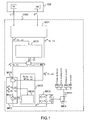
- a CMD control module receives the measurements transmitted by a triaxial accelerometer 3A and an additional sensor for measuring a vector vector vector that is substantially constant locally, in this case a triaxial 3M magnetometer for measuring the terrestrial magnetic field.
- the triaxial accelerometer 3A is connected to a mobile element EM, and the magnetometer 3M is also connected to the same mobile element EM, directly or indirectly, and its measurement axes are substantially parallel to the measurement axes of the accelerometer.
- the mobile element EM may be, for example, without limitation, a foot of a human body.
- the magnetometer is fixed in the reference of the accelerometer, the marks of the two sensors are linked by a passage matrix, and it is sufficient to perform an additional transformation to express coordinates of a reference mark. one of the sensors in the reference of the other sensor, in order to use the coordinates of the measurements of the sensors in the same reference.
- a first determination module MD1 makes it possible, from the measurements transmitted by the triaxial accelerometer 3A and the triaxial magnetometer 3M, to determine a first moment of immobility to and a second instant of immobility t n of the triaxial accelerometer, consecutive at said first moment of immobility t 0 .
- a moment of immobility corresponds to a foot support on the contact surface.
- the technique used by the first module of MD1 determination may, for example be that described in the document " Robust step detection method for pedestrian navigation systems "(DH Hwang, JH Jang, and JW Kim) published in Electronics Letters, 43 (14), July 2007 , in which the authors seek to detect a basic shape, corresponding to a typical signal for a step, in the signal of the standard accelerometers. When this shape is detected, the beginning corresponds to the instant t 0 and the end, to the instant t n .
- the successive instants t 0 , t 1 , ... t n are located in time, chronologically between the first moment of immobility t 0 and the second moment of immobility t n .
- the different successive instants t 0 , t 1 , ... t n correspond to a digitization and a sampling of the signals from the sensors followed by a calibration to go back to the measured physical quantities.
- a second determination module MD2 makes it possible to determine the plane [ u 1 , u 2 ] of said trajectory of the triaxial accelerometer 3A, from the vectors delivered by the triaxial accelerometer 3A, at different successive instants t 0 , t 1 , ..., t n , in a movable reference frame LF linked to the 3A triaxial accelerometer and 3M triaxial magnetometer.
- the second determination module MD2 can determine the plane [ u 1 , u 2 ] of said trajectory from the vectors delivered by triaxial magnetometer 3M.
- the method used by this variant is similar, replacing the measurements of the triaxial accelerometer 3A by the measurements of the triaxial magnetometer 3M.
- the plan [ u 1 , u 2 ] corresponds to the plane containing at most the measurements, considered as points or vectors in a three-dimensional space by considering the measurements transmitted for each axis of the triaxial accelerometer 3A, or respectively of the triaxial magnetometer, and the axis carried by the vector u 3 is the axis on which the projection of the measures varies the least.
- the vector u 3 is the vector normal to the plane of the trajectory [ u 1 , u 2 ], but also the axis of rotation of the triaxial accelerometer 3A.
- the second determination means form a matrix A LF with n + 1 rows, where n + 1 is the number of samples taken between t 0 and t n inclusive, and at 3 columns corresponding to the three measurements of the three axes x, y, z of the triaxial accelerometer 3A.
- AT p LF t 0 ... t not AT x LF t 0 AT there LF t 0 AT z LF t 0 ... ... ... AT x LF t not AT there LF t not AT z LF t not;
- a LF USV.
- V is a matrix with three rows and three columns, each column of which corresponds to one of the three vectors u 1 , u 2 , u 3 .
- the matrix S contains the three singular values s 1 , s 2 , s 3 . These three singular values s 1 , s 2 , s 3 , must be ranked in descending order.
- the vector u 3 is the column of the matrix V corresponding to the smallest singular value. The other two columns give the coordinates of the vectors forming the plane [ u 1 , u 2 ].
- a L F T corresponds to the transposed matrix of A LF .
- the two eigenvectors corresponding to the two largest eigenvalues correspond to the plane [ u 1 , u 2 ], the proper vector u 3 is the one corresponding to the smallest eigenvalue.
- the control module CMD also comprises a first calculation module MC1 for calculating, at successive instants t 0 , t 1 , ... t n , orthogonal projections of the vector delivered by the triaxial accelerometer 3A and the vector delivered by the magnetometer.
- the control module CMD furthermore comprises a third determination module MD3, at successive instants t 0 , t 1 , ... t n , from the rotation of the moving reference mark LF to a fixed global reference point.
- GF bound to the terrestrial reference, from the orthogonal projections of the vectors delivered by the 3M triaxial magnetometer.
- the third determination module MD3 advantageously determines an intermediate plane IF formed by the vectors b p ( t ), and b p ⁇ t , b p ( t ) being the unit vector of the terrestrial magnetic field B LF (t) and b p ⁇ t being obtained by the 90 ° rotation of the vector b p ( t ) in the plane of the trajectory or the march [ u 1 , u 2 ].
- a second calculation module MC2, of the control module CMD performs the computation, at successive instants t 0 , t 1 , ..., t n ,, of the orthogonal projection, in the fixed global coordinate system GF, of the vector delivered by the triaxial accelerometer 3A provided by the first calculation module MC1.
- the second calculation module MC2 comprises a fifth calculation module MC5 for calculating the passage in the intermediate frame IF, linked to the terrestrial frame:
- a fifth calculation module MC5 for calculating the passage in the intermediate frame IF, linked to the terrestrial frame:
- the third determination module MD3 for the rotation of the moving reference mark LF to the fixed global reference mark GF comprises an estimation module MEST of an angle ⁇ , said passage rotation being defined by an orthogonal projection on the substantially constant terrestrial magnetic field. between the two instants of immobility t 0 and t n , followed by a rotation of the estimated angle ⁇ in the plane [ u 1 , u 2 ] trajectory of the triaxial accelerometer 3A.
- the estimation module MEST makes it possible to find the rotation ⁇ (characterized by a rotation matrix M ⁇ ) to be carried out to pass from the intermediate marker IF b p t , b p ⁇ t at the benchmark Global GF in the plane of vector-driven walking ⁇ h , v ⁇ , the third vector of the global reference frame GF being u 3 .
- h is the horizontal in the plane of walking and v the vertical.
- This slope ⁇ can be estimated by the inclination of the sensors on the foot when it is supported, at t 0 or t n , considering that, the slope is constant during the duration of the step, or with the aid of a stored map outputting the slope of the contact surface of the place where the person (the mobile element EM) is located.
- the decomposition into singular values or SVD of the acceleration matrix A IF determines the matrix M ⁇ , the corresponding singular vector. at the highest singular value corresponds to the vector h .
- AT IF
- Another embodiment can also be envisaged, starting from the fact that at times t 0 and t n the foot is set, the vertical is according to the acceleration measured at this instant by the triaxial accelerometer 3A and ⁇ is the angle between AT p LF ( t 0 ) and B p LF ( t 0 ), or between AT p LF ( t n ) and B p LF ( t n ).
- the control module CMD further comprises a third calculation module MC3 for subtracting from the vector delivered by said second calculation means MC2 at said successive instants t 0 , t 1 , ... t n , the mean vector over said successive instants , so as to obtain accelerations centered in the plane [ u 1 , u 2 ] of the trajectory of the triaxial accelerometer 3A, devoid of the influence of the Earth's gravity and drifts of the device, in the fixed overall reference GF.
- a third calculation module MC3 for subtracting from the vector delivered by said second calculation means MC2 at said successive instants t 0 , t 1 , ... t n , the mean vector over said successive instants , so as to obtain accelerations centered in the plane [ u 1 , u 2 ] of the trajectory of the triaxial accelerometer 3A, devoid of the influence of the Earth's gravity and drifts of the device, in the fixed overall reference GF.
- the control module CMD also comprises a fourth calculation module MC4 of a characteristic of the trajectory of the triaxial accelerometer of the 3A starting from centered accelerations, for example by double time integration of the centered accelerations delivered by the third calculation module MC3.
- the trajectory of the triaxial accelerometer 3A ie the user's foot, in the plane of the foot trajectory during a step, expressed in the fixed global reference frame GF, between the first support and the second support, or instants of immobility, t 0 and t n .
- the fourth calculation module MC4 makes it possible to integrate twice, with respect to time, the acceleration to calculate the trajectory of the foot, or more precisely of the accelerometer linked to the foot, in the plane of the trajectory or the step.
- v and x are respectively velocity and position vectors along the two axes of the global reference ⁇ h , v ⁇ .
- the fourth calculation module MC4 can implement the double integration by more complex numerical calculation modes, for example by using Splines.
- the fourth calculation module MC4 can perform a simple integration to go up to speed.
- the control module CMD may comprise a first development module MEL1 of a direction vector, adapted to connect the respective positions of the triaxial accelerometer 3A at the first moment of immobility to and at the second moment of immobility t n , expressed in said fixed global coordinate system GF.
- the CMD control module may also comprise a second MEL2 development module of a displacement heading with respect to said vector field measured by the additional sensor, in this case with respect to the terrestrial magnetic field measured by the triaxial magnetometer 3M.
- the second MEL2 development module can develop the course as follows.
- the course of movement is defined as the angle between the Earth's magnetic north pole and the direction of travel. It should not be confused with the person's heading, which is his orientation to the North. It is often the latter which is estimated in the literature.
- the cape of the person is often supposed to be the same as the one of the displacement. However, this is the case only in the case of a walk forward but not when walking backwards, sideways, or a little skew.
- the second development module MEL2 estimates the heading of displacement and more generally the trajectory in the NED marker (North, East, Down) as follows.
- the trajectory is estimated in a plane ⁇ h , v ⁇ corresponding to the plane of the foot trajectory.
- the third vector u 3 which makes it possible to form a three-dimensional landmark ⁇ h , v , u 3 ⁇ respectively corresponding to the horizontal in the plane of the step, to the vertical in the plane of the march and to a vector normal to the plane of the march, which is also assumed horizontal.
- the component B u 3 must be substantially invariant as a function of time, which amounts to assuming a step in a plane and more generally a rotation around a substantially invariant axis and that the terrestrial magnetic field B is not disturbed.
- the second elaboration module can take the time average over the step (between the instants of immobility t 0 and t n ) as an estimate of this component.
- p 3 is the third vector forming a direct reference ⁇ p 1 , p 2 , p 3 ⁇ with the other two.
- the control module CMD can also comprise a third development module MEL3 of the distance traveled between the first and second instants of immobility t 0 and t n , ie a step, and / or during a set of intervals of successive times separating two successive instants of immobility t 0 and t n of the triaxial accelerometer, ie a succession of steps, from the data provided by the fourth calculation module.
- MEL3 of the distance traveled between the first and second instants of immobility t 0 and t n , ie a step, and / or during a set of intervals of successive times separating two successive instants of immobility t 0 and t n of the triaxial accelerometer, ie a succession of steps, from the data provided by the fourth calculation module.
- the distance traveled is given by the sum of the distances calculated for each step.
- the taking into account of the two successive moments of immobility can be replaced by the taking into account of two successive instants for which the velocity vectors in the plane of the trajectory are known, as well as of the angle ⁇ at these points.
- these data can be measured by additional sensors or estimated from measurements provided by additional sensors.
- the fourth calculation module must initialize the speed with the speed of the first moment and add a constant depending on the velocities of the two moments to the acceleration centered.
- the second determination module MD2 estimates the axis of rotation using the additional triaxial sensor
- the first calculation module MC1 also performs a projection according to the vector u 3
- the third calculation module MC3 calculates the acceleration centered on the vector u 3
- the fourth calculation module MC4 integrates the latter centered acceleration, once to obtain the speed, or twice for the position.
- the present invention makes it possible, at reduced cost, to determine a planar trajectory of a triaxial accelerometer linked to a mobile element, in particular a foot, precisely and at a reduced cost.
- the movable element may be another part of the human body, such as a hand, part of an animal body, or part of an artificial body such as a computer robot or mouse.
Claims (18)
- Vorrichtung zum Bestimmen einer Charakteristik eines Pfades, der von aufeinander folgenden Positionen eines triaxialen Beschleunigungsmessers (3A) gebildet wird, der fest mit einem beweglichen Element (EM) verbunden ist, zwischen einem ersten Immobilitätszeitpunkt (t0) und einem auf den ersten Immobilitätszeitpunkt (t0) folgenden zweiten Immobilitätszeitpunkt (tn) des triaxialen Beschleunigungsmessers (3A), wobei die Vorrichtung ferner einen zusätzlichen triaxialen Sensor zum Messen eines Vektors eines im Wesentlichen konstanten Vektorfeldes zwischen dem ersten und dem zweiten Immobilitätszeitpunkt (t0, tn), in einem mit dem terrestrischen Bezugspunkt verbundenen festen globalen Bezugspunkt (GF), wobei der zusätzliche Sensor fest mit dem beweglichen Element (EM) verbunden und im Bezugspunkt des Beschleunigungsmessers (3A) fest ist, und Steuermittel (CMD) umfasst, wobei die Steuermittel (CMD) Folgendes umfassen:- erste Mittel (MD1) zum Bestimmen des ersten und zweiten Immobilitätszeitpunkts (t0, tn) des triaxialen Beschleunigungsmessers (3A);- zweite Mittel (MD2) zum Bestimmen einer im Wesentlichen invarianten Rotationsachse des triaxialen Beschleunigungsmessers (3A) zwischen dem ersten und zweiten Immobilitätszeitpunkt (t0, tn) und einer Ebene orthogonal zu der im Wesentlichen invarianten Rotationsachse, in einem beweglichen Bezugspunkt (LF), der mit dem Beschleunigungsmesser (3A) oder dem zusätzlichen Sensor verbunden ist, auf der Basis von durch den triaxialen Beschleunigungsmesser (3A) gelieferten Vektoren oder auf der Basis von vom zusätzlichen Sensor gelieferten Vektoren;
dadurch gekennzeichnet, dass die Steuermittel (CMD) Folgendes umfassen:- erste Mittel (MC1) zum Berechnen, zu den aufeinander folgenden Zeitpunkten (to, t1, ..., tn), von ersten orthogonalen Projektionen auf der Ebene der vom triaxialen Beschleunigungsmesser (3A) gelieferten Vektoren und von vom zusätzlichen Sensor gelieferten Vektoren in dem beweglichen Bezugspunkt (LF);- dritte Mittel (MD3) zum Bestimmen, zu den aufeinander folgenden Zeitpunkten (to, t1, ..., tn), der Passagerotation von dem beweglichen Bezugspunkt (LF) zu dem festen globalen Bezugspunkt (GF) auf der Basis der ersten orthogonalen Projektionen der von dem zusätzlichen Sensor gelieferten Vektoren;- zweite Mittel (MC2) zum Berechnen, zu den aufeinander folgenden Zeitpunkten (t0, t1, ..., tn), von zweiten orthogonalen Projektionen in dem globalen festen Bezugspunkt (GF), von den ersten orthogonalen Projektionen in der Ebene der von dem triaxialen Beschleunigungsmesser (3A) gelieferten Vektoren, geliefert von den ersten Rechenmitteln (MC1);- dritte Rechenmittel (MC3) zum Subtrahieren, von jeder zweiten orthogonalen Projektion in dem festen globalen Bezugspunkt (GF), des mittleren Vektors zu den aufeinander folgenden Zeitpunkten (t0, t1, ..., tn), um die in der Ebene zentrierten Beschleunigungen zu erhalten, ohne den Einfluss von Erdanziehung und von Abweichungen der Vorrichtung, in dem festen globalen Bezugspunkt (GF); und- vierte Mittel (MC4) zum Berechnen einer Charakteristik des Pfades auf der Basis der zentrierten Beschleunigungen. - Vorrichtung nach Anspruch 1, bei der die aufeinander folgenden Positionen im Wesentlichen koplanar sind.
- Vorrichtung nach Anspruch 1 oder 2, bei der das bewegliche Element (EM) ein Fuß ist, wobei das den ersten und den zweiten Immobilitätszeitpunkt (t0, tn) des triaxialen Beschleunigungsmessers (3A) trennende Zeitintervall einem Schritt des Fußes entspricht.
- Vorrichtung nach einem der Ansprüche 1 bis 3, bei der die Steuermittel (CMD) erste Mittel (MEL1) zum Ausarbeiten eines Richtungsvektors umfassen, ausgelegt zum Verbinden der jeweiligen Positionen des triaxialen Beschleunigungsmessers (3A) zu dem ersten Immobilitätszeitpunkt (t0) und dem zweiten Immobilitätszeitpunkt (tn), ausgedrückt in dem festen globalen Bezugspunkt (GF).
- Vorrichtung nach Anspruch 4, bei der, da die Ebene des Pfades vertikal ist, die Steuermittel (CMD) ferner zweite Mittel (MEL2) zum Ausarbeiten eines Kurses der Bewegung in Bezug auf das von dem zusätzlichen Sensor gemessene Vektorfeld umfassen, wobei die zweiten Ausarbeitungsmittel (MEL2) zum Bewirken einer orthogonalen Projektion des vom zusätzlichen Sensor gemessenen Vektorfeldvektors in einer horizontalen Ebene orthogonal zur Ebene des Pfades umfassen.
- Vorrichtung nach einem der Ansprüche 1 bis 5, bei der, da die Ebene des Pfades vertikal ist, die zweiten Mittel (MD2) zum Ermitteln der Ebene des Pfades des triaxialen Beschleunigungsmessers (3A) ausgelegt sind zum:- Bewirken einer Zerlegung der Dreispaltenmatrix
 - Bewirken einer Zerlegung der Autokorrelationsmatrix der Dreispaltenmatrix, die von den durch den triaxialen Beschleunigungsmesser (3A) zu den aufeinander folgenden Zeitpunkten (t0, t1, ..., tn) gelieferten Vektoren gebildet wird, in Eigenwerte und Eigenvektoren, in dem beweglichen Bezugspunkt (LF), und Extrahieren der beiden Eigenvektoren, die den beiden größten Eigenwerten entsprechen.
 - Vorrichtung nach einem der Ansprüche 1 bis 6, bei der die zweiten Rechenmittel (MC2) fünfte Mittel (MC5) zum Berechnen der Passage in einem Zwischenbezugspunkt (IF) umfassen, der mit dem terrestrischen Bezugspunkt verbunden ist, definiert durch einen von den ersten Rechenmitteln (MC1) gelieferten ersten Vektor, auf der Basis eines von dem zusätzlichen Sensor gelieferten Vektors, und durch einen zweiten Vektor, orthogonal zu dem ersten Vektor, der zur Ebene des Pfades gehört.
- Vorrichtung nach einem der Ansprüche 1 bis 7, bei der die dritten Mittel (MD3) zum Bestimmen der Passagerotation von dem beweglichen Bezugspunkt (LF) zu dem festen globalen Bezugspunkt (GF) Mittel (MEST) zum Schätzen eines Winkels (α) umfassen, wobei die Passagerotation durch eine orthogonale Projektion auf dem im Wesentlichen konstanten Vektorfeld definiert wird, gefolgt von einer Rotation des geschätzten Winkels (α) in der Ebene des Pfades des triaxialen Beschleunigungsmessers (3A).
- Vorrichtung nach Anspruch 8, bei der die Schätzmittel (MEST) zum Schätzen des Winkels (α) ausgelegt sind:- auf der Basis der Neigung (θ) der Kontaktfläche des beweglichen Elements (EM) und des von den fünften Rechenmitteln (MC5) übertragenen Vektors auf der Basis des vom triaxialen Beschleunigungsmesser (3A) übertragenen Vektors; oder- auf der Basis einer Zerlegung der von den fünften Rechenmitteln (MC5) gelieferten Dreispaltenmatrix in Einzelwerte, auf der Basis der Matrix (AIF), die von den vom triaxialen Beschleunigungsmesser (3A) zu den aufeinander folgenden Zeitpunkten (to, t1, ..., tn) gelieferten Vektoren gebildet wird; oder- als Winkel, zum ersten oder zweiten Immobilitätszeitpunkt (to, tn), zwischen dem Vektor, der von den ersten Rechenmitteln (MC1) geliefert wird, auf der Basis des vom zusätzlichen Sensor gelieferten Vektors, und dem Vektor, der von den ersten Rechenmitteln (MC1) geliefert wird, auf der Basis des vom triaxialen Beschleunigungsmesser (3A) gelieferten Vektors.
- Vorrichtung nach einem der vorherigen Ansprüche, bei der die Steuermittel (CMD) dritte Mittel (MEL3) zum Ausarbeiten der Distanz umfassen, die von dem triaxialen Beschleunigungsmesser (3A) zwischen dem ersten und zweiten Immobilitätszeitpunkt (t0, tn) durchlaufen wird, und/oder bei einem Satz von aufeinander folgenden Zeitintervallen, die zwei aufeinander folgende Immobilitätszeitpunkte (t0, tn) des triaxialen Beschleunigungsmessers (3A) trennen, auf der Basis von Daten, die von den vierten Rechenmitteln (MC4) geliefert werden.
- Vorrichtung nach einem der vorherigen Ansprüche, bei der die Steuermittel (CMD) vierte Mittel (MEL4) zum Ausarbeiten eines Pfades während eines Satzes von aufeinander folgenden Zeitintervallen umfassen, die zwei aufeinander folgende Immobilitätszeitpunkte (t0, tn) des triaxialen Beschleunigungsmessers (3A) trennen, auf der Basis der Charakteristik des von den vierten Rechenmitteln (MC4) gelieferten Pfades.
- Vorrichtung nach einem der vorherigen Ansprüche, bei der der zusätzliche Sensor ein triaxiales Magnetometer (3M) zum Messen des terrestrischen Magnetfeldes, im Wesentlichen konstant, zwischen dem ersten und zweiten Immobilitätszeitpunkt (to, tn) ist.
- Vorrichtung nach einem der vorherigen Ansprüche, bei der der triaxiale Beschleunigungsmesser (3A) so angeordnet ist, dass er im Wesentlichen an der Kontaktfläche des beweglichen Elements (EM) zu einem Immobilitätszeitpunkt des triaxialen Beschleunigungsmessers (3A) angeordnet ist.
- Vorrichtung nach einem der vorherigen Ansprüche, bei der der zusätzliche Sensor so angeordnet ist, dass er sich in einer Distanz von der Kontaktfläche des beweglichen Elements (EM) zu einem Immobilitätszeitpunkt des triaxialen Beschleunigungsmessers (3A) befindet.
- Vorrichtung nach einem der vorherigen Ansprüche, bei der die Steuermittel (CMD) mit dem beweglichen Element (EM) verbunden oder in einer Distanz von dem beweglichen Element (EM) angeordnet und zum Arbeiten in Echtzeit oder zeitversetzt ausgelegt sind.
- System, das wenigstens eine Vorrichtung nach einem der Ansprüche 3 bis 15 umfasst, wobei das System Folgendes sein kann:- ein Videospielsystem, das eine visuelle oder akustische Anzeige zum Anzeigen von wenigstens einem vom Spieler auszuführenden Schritt umfasst, oder- ein Sprunganalysesystem, oder- ein externes oder internes Geolokalisierungssystem, oder- ein System zum Berechnen des Energieverbrauchs eines Nutzers.
- System nach einem der vorherigen Ansprüche, bei dem die Charakteristik des Pfades des triaxialen Beschleunigungsmessers (3A) die Geschwindigkeit des triaxialen Beschleunigungsmessers (3A) und/oder den Pfad des triaxialen Beschleunigungsmessers (3A) umfasst.
- Verfahren zum Bestimmen einer Charakteristik eines Pfades, der von aufeinander folgenden Positionen eines triaxialen Beschleunigungsmessers (3A) gebildet wird, der fest mit einem beweglichen Element (EM) verbunden ist, zwischen einem ersten Immobilitätszeitpunkt (t0) und einem auf den ersten Immobilitätszeitpunkt (t0) folgenden zweiten Immobilitätszeitpunkt (tn) des triaxialen Beschleunigungsmessers, ferner unter Verwendung eines triaxialen zusätzlichen Sensors zum Messen eines Vektors eines im Wesentlichen konstanten Vektorfeldes zwischen dem ersten und dem zweiten Immobilitätszeitpunkt (t0, tn) in einem festen globalen Bezugspunkt (GF), der mit dem terrestrischen Bezugspunkt verbunden ist, wobei der zusätzliche Sensor fest mit dem beweglichen Element (EM) verbunden und in dem Bezugspunkt des Beschleunigungsmessers (3A) fest ist, wobei das Verfahren von einer Vorrichtung ausgeführt wird, die den triaxialen Beschleunigungsmesser und den triaxialen zusätzlichen Sensor umfasst, und die folgenden Schritte beinhaltet:- Bestimmen des ersten und zweiten Immobilitätszeitpunkts (t0, tn) des triaxialen Beschleunigungsmessers (3A);- Bestimmen einer im Wesentlichen invarianten Rotationsachse des triaxialen Beschleunigungsmessers zwischen dem ersten und dem zweiten Immobilitätszeitpunkt, und Bestimmen einer Ebene orthogonal zu der im Wesentlichen invarianten Rotationsachse in einem beweglichen Bezugspunkt (LF), der mit dem Beschleunigungsmesser (3A) oder dem zusätzlichen Sensor verbunden ist, auf der Basis der von dem triaxialen Beschleunigungsmesser (3A) gelieferten Vektoren oder auf der Basis der von dem zusätzlichen Sensor gelieferten Vektoren;
wobei das Verfahren dadurch gekennzeichnet ist, dass es die folgenden Schritte beinhaltet:- Berechnen, zu den aufeinander folgenden Zeitpunkten (t0, t1, ..., tn), von ersten orthogonalen Projektionen in der Ebene, von von dem triaxialen Beschleunigungsmesser (3A) gelieferten Vektoren und von von dem zusätzlichen Sensor gelieferten Vektoren in dem beweglichen Bezugspunkt;- Bestimmen, zu den aufeinander folgenden Zeitpunkten (to, t1, ..., tn), der Passagerotation von dem beweglichen Bezugspunkt (LF) zu dem festen globalen Bezugspunkt (GF), auf der Basis der ersten orthogonalen Projektionen der von dem zusätzlichen Sensor gelieferten Vektoren;- Berechnen, zu den aufeinander folgenden Zeitpunkten (to, t1, ..., tn), von zweiten orthogonalen Projektionen in dem festen globalen Bezugspunkt der ersten orthogonalen Projektionen in der Ebene der von dem triaxialen Beschleunigungsmesser gelieferten Vektoren;- Subtrahieren von jeder zweiten orthogonalen Projektion in dem festen globalen Bezugspunkt des mittleren Vektors zu den aufeinander folgenden Zeitpunkten (to, t1, ..., tn), um die in der Ebene zentrierten Beschleunigungen zu erhalten, ohne den Einfluss der Erdanziehung und von Abweichungen der Vorrichtung, in dem globalen festen Bezugspunkt (GF); und- Bestimmen einer Charakteristik des Pfades auf der Basis der zentrierten Beschleunigungen.
Applications Claiming Priority (2)
| Application Number | Priority Date | Filing Date | Title |
|---|---|---|---|
| FR0857181A FR2937423B1 (fr) | 2008-10-22 | 2008-10-22 | Dispositif de determination d'une trajectoire formee de positions successives sensiblement coplanaires d'un accelerometre triaxial lie de maniere solidaire a un element mobile |
| PCT/EP2009/063741 WO2010046364A1 (fr) | 2008-10-22 | 2009-10-20 | Dispositif et procede de determination d'une caracteristique d'une trajectoire formee de positions successives d'un accelerometre triaxial lie de maniere solidaire a un element mobile |
Publications (2)
| Publication Number | Publication Date |
|---|---|
| EP2350565A1 EP2350565A1 (de) | 2011-08-03 |
| EP2350565B1 true EP2350565B1 (de) | 2014-06-18 |
Family
ID=40909976
Family Applications (1)
| Application Number | Title | Priority Date | Filing Date |
|---|---|---|---|
| EP09736970.6A Active EP2350565B1 (de) | 2008-10-22 | 2009-10-20 | Einrichtung und verfahren zum bestimmen eines charakteristikums eines durch aufeinanderfolgende positionen eines starr mit einem mobilen element verbundenen triaxialbeschleunigungsmessers gebildeten pfads |
Country Status (7)
| Country | Link |
|---|---|
| US (1) | US9068842B2 (de) |
| EP (1) | EP2350565B1 (de) |
| JP (1) | JP5754051B2 (de) |
| KR (1) | KR101680394B1 (de) |
| CN (1) | CN102239387B (de) |
| FR (1) | FR2937423B1 (de) |
| WO (1) | WO2010046364A1 (de) |
Families Citing this family (15)
| Publication number | Priority date | Publication date | Assignee | Title |
|---|---|---|---|---|
| US20120016624A1 (en) * | 2009-01-05 | 2012-01-19 | Commissariat A L'Energie Atomique Et Aux Engeries Alternatives | Device and method for characterizing movements |
| US8471869B1 (en) | 2010-11-02 | 2013-06-25 | Google Inc. | Optimizing display orientation |
| US8797358B1 (en) | 2010-11-02 | 2014-08-05 | Google Inc. | Optimizing display orientation |
| US9357948B2 (en) | 2010-12-01 | 2016-06-07 | Commissariat A L'energie Atomique Et Aux Energies Alternatives | Method and system for determining the values of parameters representative of a movement of at least two limbs of an entity represented in the form of an articulated line |
| CN102915130B (zh) * | 2011-08-04 | 2016-03-23 | 王振兴 | 移动轨迹校正方法及移动轨迹产生方法 |
| US8914037B2 (en) | 2011-08-11 | 2014-12-16 | Qualcomm Incorporated | Numerically stable computation of heading without a reference axis |
| US20130046505A1 (en) * | 2011-08-15 | 2013-02-21 | Qualcomm Incorporated | Methods and apparatuses for use in classifying a motion state of a mobile device |
| FR3000376B1 (fr) * | 2013-01-02 | 2015-02-20 | Movea | Procede d'estimation de mouvement d'un objet massique poly-articule |
| CN103476116B (zh) * | 2013-09-23 | 2016-10-12 | 东南大学 | 基于定位单元质量及多算法数据融合的抗NLoS误差定位方法 |
| US9696165B2 (en) * | 2015-02-03 | 2017-07-04 | The Regents Of The University Of Michigan | Last-mile navigation using smartphones |
| US9719787B2 (en) * | 2015-02-26 | 2017-08-01 | Invensense, Inc. | Method and system for multiple pass smoothing |
| KR101698681B1 (ko) * | 2015-08-26 | 2017-01-23 | 매그나칩 반도체 유한회사 | 지자기력의 수평 경사각 산출 방법 및 이를 이용한 장치 |
| US10041800B2 (en) | 2016-09-23 | 2018-08-07 | Qualcomm Incorporated | Pedestrian sensor assistance in a mobile device during typical device motions |
| CN108908331B (zh) * | 2018-07-13 | 2022-04-22 | 哈尔滨工业大学(深圳) | 超冗余柔性机器人的避障方法及系统、计算机存储介质 |
| FR3104703B1 (fr) * | 2019-12-11 | 2022-01-07 | Fingermind | Procede, dispositif utilisateur et produit programme d’ordinateur de determination d’une localisation |
Citations (1)
| Publication number | Priority date | Publication date | Assignee | Title |
|---|---|---|---|---|
| JP2008116315A (ja) * | 2006-11-02 | 2008-05-22 | Yamaha Corp | 歩行ナビゲーション方法、システムおよびプログラム |
Family Cites Families (8)
| Publication number | Priority date | Publication date | Assignee | Title |
|---|---|---|---|---|
| JP3532773B2 (ja) * | 1998-09-26 | 2004-05-31 | ジヤトコ株式会社 | 携帯用位置検出装置および位置管理システム |
| US6529827B1 (en) * | 1999-11-01 | 2003-03-04 | Garmin Corporation | GPS device with compass and altimeter and method for displaying navigation information |
| US6594617B2 (en) * | 2000-08-18 | 2003-07-15 | Applanix Corporation | Pedometer navigator system |
| FR2856145B1 (fr) * | 2003-06-16 | 2005-09-02 | Michelin Soc Tech | Detection des revolutions d'un ensemble pneumatique et roue, a l'aide du champ magnetique terrestre. |
| WO2006104140A1 (ja) * | 2005-03-28 | 2006-10-05 | Asahi Kasei Emd Corporation | 進行方向計測装置及び進行方向計測方法 |
| KR100703451B1 (ko) * | 2005-09-16 | 2007-04-03 | 삼성전자주식회사 | 개인 항법 기기에서 걸음 검출 장치 및 방법 |
| JP2008175559A (ja) * | 2007-01-16 | 2008-07-31 | Yokogawa Electric Corp | 歩行分析システム |
| US8221290B2 (en) * | 2007-08-17 | 2012-07-17 | Adidas International Marketing B.V. | Sports electronic training system with electronic gaming features, and applications thereof |
-
2008
- 2008-10-22 FR FR0857181A patent/FR2937423B1/fr not_active Expired - Fee Related
-
2009
- 2009-10-20 JP JP2011532611A patent/JP5754051B2/ja not_active Expired - Fee Related
- 2009-10-20 US US13/125,145 patent/US9068842B2/en active Active
- 2009-10-20 EP EP09736970.6A patent/EP2350565B1/de active Active
- 2009-10-20 CN CN200980148751.5A patent/CN102239387B/zh active Active
- 2009-10-20 KR KR1020117011638A patent/KR101680394B1/ko active IP Right Grant
- 2009-10-20 WO PCT/EP2009/063741 patent/WO2010046364A1/fr active Application Filing
Patent Citations (1)
| Publication number | Priority date | Publication date | Assignee | Title |
|---|---|---|---|---|
| JP2008116315A (ja) * | 2006-11-02 | 2008-05-22 | Yamaha Corp | 歩行ナビゲーション方法、システムおよびプログラム |
Also Published As
| Publication number | Publication date |
|---|---|
| KR20110094009A (ko) | 2011-08-19 |
| US20110264400A1 (en) | 2011-10-27 |
| CN102239387A (zh) | 2011-11-09 |
| CN102239387B (zh) | 2015-11-25 |
| WO2010046364A1 (fr) | 2010-04-29 |
| US9068842B2 (en) | 2015-06-30 |
| FR2937423A1 (fr) | 2010-04-23 |
| JP2012506550A (ja) | 2012-03-15 |
| JP5754051B2 (ja) | 2015-07-22 |
| KR101680394B1 (ko) | 2016-12-12 |
| FR2937423B1 (fr) | 2012-05-25 |
| EP2350565A1 (de) | 2011-08-03 |
Similar Documents
| Publication | Publication Date | Title |
|---|---|---|
| EP2350565B1 (de) | Einrichtung und verfahren zum bestimmen eines charakteristikums eines durch aufeinanderfolgende positionen eines starr mit einem mobilen element verbundenen triaxialbeschleunigungsmessers gebildeten pfads | |
| EP2560551B1 (de) | System zur analyse der fortschritte eines benutzers | |
| EP1984696B1 (de) | Bewegungserfassungsvorrichtung und entsprechendes verfahren | |
| Skog et al. | Zero-velocity detection—An algorithm evaluation | |
| EP3359915B1 (de) | Verfahren zur schätzung der bewegung eines fussgängers | |
| EP2646776B1 (de) | Verfahren und system zur bestimmung der werte der charakteristischen parameter einer bewegung von mindestens zwei gliedmassen einer einheit in form einer gelenkigen leitung | |
| EP1886517B1 (de) | Verfahren und Einrichtung zur Ortsbestimmung eines Endgeräts in einem drahtlosen lokalen Netzwerk | |
| EP2118621B1 (de) | Einrichtung und verfahren zur bestimmung des wegs eines sich in zwei dimensionen bewegenden objekts | |
| EP3201633B1 (de) | Verfahren und systeme zur festlegung einer vertikalen bahn und automatischen erkennung von sprüngen | |
| FR3012597B1 (fr) | Procede de localisation en interieur et exterieur et dispositif portatif mettant en œuvre un tel procede | |
| EP2494366B1 (de) | System und verfahren zur zählung der richtungsänderungen einer person | |
| TW200916730A (en) | Augmented navigation system and method of a moving object | |
| US10520330B2 (en) | Estimation of direction of motion of users on mobile devices | |
| EP3408612B1 (de) | Verfahren zur kalkulation der physischen aktivität einer oberen gliedmasse | |
| JP2011047950A (ja) | デッドレコニング装置 | |
| JP2007309803A (ja) | デッドレコニング装置 | |
| Chang et al. | Cycling dead reckoning for enhanced portable device navigation on multi-gear bicycles | |
| Jung et al. | A novel method for energy expenditure using multisensor based activity monitoring | |
| WO2024009048A1 (fr) | Procede de recalage d'une attitude fournie par un systeme de navigation a l'estime au moyen d'un systeme de positionnement relatif |
Legal Events
| Date | Code | Title | Description |
|---|---|---|---|
| PUAI | Public reference made under article 153(3) epc to a published international application that has entered the european phase |
Free format text: ORIGINAL CODE: 0009012 |
|
| 17P | Request for examination filed |
Effective date: 20110505 |
|
| AK | Designated contracting states |
Kind code of ref document: A1 Designated state(s): AT BE BG CH CY CZ DE DK EE ES FI FR GB GR HR HU IE IS IT LI LT LU LV MC MK MT NL NO PL PT RO SE SI SK SM TR |
|
| DAX | Request for extension of the european patent (deleted) | ||
| GRAP | Despatch of communication of intention to grant a patent |
Free format text: ORIGINAL CODE: EPIDOSNIGR1 |
|
| INTG | Intention to grant announced |
Effective date: 20140127 |
|
| GRAS | Grant fee paid |
Free format text: ORIGINAL CODE: EPIDOSNIGR3 |
|
| GRAA | (expected) grant |
Free format text: ORIGINAL CODE: 0009210 |
|
| AK | Designated contracting states |
Kind code of ref document: B1 Designated state(s): AT BE BG CH CY CZ DE DK EE ES FI FR GB GR HR HU IE IS IT LI LT LU LV MC MK MT NL NO PL PT RO SE SI SK SM TR |
|
| REG | Reference to a national code |
Ref country code: GB Ref legal event code: FG4D Free format text: NOT ENGLISH |
|
| REG | Reference to a national code |
Ref country code: CH Ref legal event code: EP |
|
| REG | Reference to a national code |
Ref country code: AT Ref legal event code: REF Ref document number: 673603 Country of ref document: AT Kind code of ref document: T Effective date: 20140715 |
|
| REG | Reference to a national code |
Ref country code: IE Ref legal event code: FG4D Free format text: LANGUAGE OF EP DOCUMENT: FRENCH |
|
| REG | Reference to a national code |
Ref country code: DE Ref legal event code: R096 Ref document number: 602009024760 Country of ref document: DE Effective date: 20140731 |
|
| PG25 | Lapsed in a contracting state [announced via postgrant information from national office to epo] |
Ref country code: GR Free format text: LAPSE BECAUSE OF FAILURE TO SUBMIT A TRANSLATION OF THE DESCRIPTION OR TO PAY THE FEE WITHIN THE PRESCRIBED TIME-LIMIT Effective date: 20140919 Ref country code: NO Free format text: LAPSE BECAUSE OF FAILURE TO SUBMIT A TRANSLATION OF THE DESCRIPTION OR TO PAY THE FEE WITHIN THE PRESCRIBED TIME-LIMIT Effective date: 20140918 Ref country code: CY Free format text: LAPSE BECAUSE OF FAILURE TO SUBMIT A TRANSLATION OF THE DESCRIPTION OR TO PAY THE FEE WITHIN THE PRESCRIBED TIME-LIMIT Effective date: 20140618 Ref country code: LT Free format text: LAPSE BECAUSE OF FAILURE TO SUBMIT A TRANSLATION OF THE DESCRIPTION OR TO PAY THE FEE WITHIN THE PRESCRIBED TIME-LIMIT Effective date: 20140618 Ref country code: FI Free format text: LAPSE BECAUSE OF FAILURE TO SUBMIT A TRANSLATION OF THE DESCRIPTION OR TO PAY THE FEE WITHIN THE PRESCRIBED TIME-LIMIT Effective date: 20140618 |
|
| REG | Reference to a national code |
Ref country code: NL Ref legal event code: VDEP Effective date: 20140618 |
|
| REG | Reference to a national code |
Ref country code: AT Ref legal event code: MK05 Ref document number: 673603 Country of ref document: AT Kind code of ref document: T Effective date: 20140618 |
|
| REG | Reference to a national code |
Ref country code: LT Ref legal event code: MG4D |
|
| PG25 | Lapsed in a contracting state [announced via postgrant information from national office to epo] |
Ref country code: LV Free format text: LAPSE BECAUSE OF FAILURE TO SUBMIT A TRANSLATION OF THE DESCRIPTION OR TO PAY THE FEE WITHIN THE PRESCRIBED TIME-LIMIT Effective date: 20140618 Ref country code: HR Free format text: LAPSE BECAUSE OF FAILURE TO SUBMIT A TRANSLATION OF THE DESCRIPTION OR TO PAY THE FEE WITHIN THE PRESCRIBED TIME-LIMIT Effective date: 20140618 Ref country code: SE Free format text: LAPSE BECAUSE OF FAILURE TO SUBMIT A TRANSLATION OF THE DESCRIPTION OR TO PAY THE FEE WITHIN THE PRESCRIBED TIME-LIMIT Effective date: 20140618 |
|
| PG25 | Lapsed in a contracting state [announced via postgrant information from national office to epo] |
Ref country code: CZ Free format text: LAPSE BECAUSE OF FAILURE TO SUBMIT A TRANSLATION OF THE DESCRIPTION OR TO PAY THE FEE WITHIN THE PRESCRIBED TIME-LIMIT Effective date: 20140618 Ref country code: EE Free format text: LAPSE BECAUSE OF FAILURE TO SUBMIT A TRANSLATION OF THE DESCRIPTION OR TO PAY THE FEE WITHIN THE PRESCRIBED TIME-LIMIT Effective date: 20140618 Ref country code: RO Free format text: LAPSE BECAUSE OF FAILURE TO SUBMIT A TRANSLATION OF THE DESCRIPTION OR TO PAY THE FEE WITHIN THE PRESCRIBED TIME-LIMIT Effective date: 20140618 Ref country code: SK Free format text: LAPSE BECAUSE OF FAILURE TO SUBMIT A TRANSLATION OF THE DESCRIPTION OR TO PAY THE FEE WITHIN THE PRESCRIBED TIME-LIMIT Effective date: 20140618 Ref country code: ES Free format text: LAPSE BECAUSE OF FAILURE TO SUBMIT A TRANSLATION OF THE DESCRIPTION OR TO PAY THE FEE WITHIN THE PRESCRIBED TIME-LIMIT Effective date: 20140618 Ref country code: PT Free format text: LAPSE BECAUSE OF FAILURE TO SUBMIT A TRANSLATION OF THE DESCRIPTION OR TO PAY THE FEE WITHIN THE PRESCRIBED TIME-LIMIT Effective date: 20141020 |
|
| PG25 | Lapsed in a contracting state [announced via postgrant information from national office to epo] |
Ref country code: IS Free format text: LAPSE BECAUSE OF FAILURE TO SUBMIT A TRANSLATION OF THE DESCRIPTION OR TO PAY THE FEE WITHIN THE PRESCRIBED TIME-LIMIT Effective date: 20141018 Ref country code: NL Free format text: LAPSE BECAUSE OF FAILURE TO SUBMIT A TRANSLATION OF THE DESCRIPTION OR TO PAY THE FEE WITHIN THE PRESCRIBED TIME-LIMIT Effective date: 20140618 Ref country code: AT Free format text: LAPSE BECAUSE OF FAILURE TO SUBMIT A TRANSLATION OF THE DESCRIPTION OR TO PAY THE FEE WITHIN THE PRESCRIBED TIME-LIMIT Effective date: 20140618 Ref country code: PL Free format text: LAPSE BECAUSE OF FAILURE TO SUBMIT A TRANSLATION OF THE DESCRIPTION OR TO PAY THE FEE WITHIN THE PRESCRIBED TIME-LIMIT Effective date: 20140618 |
|
| REG | Reference to a national code |
Ref country code: DE Ref legal event code: R097 Ref document number: 602009024760 Country of ref document: DE |
|
| PLBE | No opposition filed within time limit |
Free format text: ORIGINAL CODE: 0009261 |
|
| STAA | Information on the status of an ep patent application or granted ep patent |
Free format text: STATUS: NO OPPOSITION FILED WITHIN TIME LIMIT |
|
| PG25 | Lapsed in a contracting state [announced via postgrant information from national office to epo] |
Ref country code: DK Free format text: LAPSE BECAUSE OF FAILURE TO SUBMIT A TRANSLATION OF THE DESCRIPTION OR TO PAY THE FEE WITHIN THE PRESCRIBED TIME-LIMIT Effective date: 20140618 |
|
| 26N | No opposition filed |
Effective date: 20150319 |
|
| PG25 | Lapsed in a contracting state [announced via postgrant information from national office to epo] |
Ref country code: LU Free format text: LAPSE BECAUSE OF FAILURE TO SUBMIT A TRANSLATION OF THE DESCRIPTION OR TO PAY THE FEE WITHIN THE PRESCRIBED TIME-LIMIT Effective date: 20141020 Ref country code: MC Free format text: LAPSE BECAUSE OF FAILURE TO SUBMIT A TRANSLATION OF THE DESCRIPTION OR TO PAY THE FEE WITHIN THE PRESCRIBED TIME-LIMIT Effective date: 20140618 |
|
| REG | Reference to a national code |
Ref country code: CH Ref legal event code: PL |
|
| PG25 | Lapsed in a contracting state [announced via postgrant information from national office to epo] |
Ref country code: BE Free format text: LAPSE BECAUSE OF NON-PAYMENT OF DUE FEES Effective date: 20141031 |
|
| REG | Reference to a national code |
Ref country code: IE Ref legal event code: MM4A |
|
| PG25 | Lapsed in a contracting state [announced via postgrant information from national office to epo] |
Ref country code: CH Free format text: LAPSE BECAUSE OF NON-PAYMENT OF DUE FEES Effective date: 20141031 Ref country code: LI Free format text: LAPSE BECAUSE OF NON-PAYMENT OF DUE FEES Effective date: 20141031 Ref country code: SI Free format text: LAPSE BECAUSE OF FAILURE TO SUBMIT A TRANSLATION OF THE DESCRIPTION OR TO PAY THE FEE WITHIN THE PRESCRIBED TIME-LIMIT Effective date: 20140618 |
|
| PG25 | Lapsed in a contracting state [announced via postgrant information from national office to epo] |
Ref country code: IE Free format text: LAPSE BECAUSE OF NON-PAYMENT OF DUE FEES Effective date: 20141020 |
|
| PG25 | Lapsed in a contracting state [announced via postgrant information from national office to epo] |
Ref country code: SM Free format text: LAPSE BECAUSE OF FAILURE TO SUBMIT A TRANSLATION OF THE DESCRIPTION OR TO PAY THE FEE WITHIN THE PRESCRIBED TIME-LIMIT Effective date: 20140618 |
|
| PG25 | Lapsed in a contracting state [announced via postgrant information from national office to epo] |
Ref country code: BG Free format text: LAPSE BECAUSE OF FAILURE TO SUBMIT A TRANSLATION OF THE DESCRIPTION OR TO PAY THE FEE WITHIN THE PRESCRIBED TIME-LIMIT Effective date: 20140618 |
|
| PG25 | Lapsed in a contracting state [announced via postgrant information from national office to epo] |
Ref country code: TR Free format text: LAPSE BECAUSE OF FAILURE TO SUBMIT A TRANSLATION OF THE DESCRIPTION OR TO PAY THE FEE WITHIN THE PRESCRIBED TIME-LIMIT Effective date: 20140618 Ref country code: MT Free format text: LAPSE BECAUSE OF FAILURE TO SUBMIT A TRANSLATION OF THE DESCRIPTION OR TO PAY THE FEE WITHIN THE PRESCRIBED TIME-LIMIT Effective date: 20140618 Ref country code: HU Free format text: LAPSE BECAUSE OF FAILURE TO SUBMIT A TRANSLATION OF THE DESCRIPTION OR TO PAY THE FEE WITHIN THE PRESCRIBED TIME-LIMIT; INVALID AB INITIO Effective date: 20091020 |
|
| REG | Reference to a national code |
Ref country code: FR Ref legal event code: PLFP Year of fee payment: 8 |
|
| REG | Reference to a national code |
Ref country code: FR Ref legal event code: PLFP Year of fee payment: 9 |
|
| PG25 | Lapsed in a contracting state [announced via postgrant information from national office to epo] |
Ref country code: MK Free format text: LAPSE BECAUSE OF FAILURE TO SUBMIT A TRANSLATION OF THE DESCRIPTION OR TO PAY THE FEE WITHIN THE PRESCRIBED TIME-LIMIT Effective date: 20140618 |
|
| REG | Reference to a national code |
Ref country code: FR Ref legal event code: PLFP Year of fee payment: 10 |
|
| PGFP | Annual fee paid to national office [announced via postgrant information from national office to epo] |
Ref country code: IT Payment date: 20210929 Year of fee payment: 13 |
|
| PG25 | Lapsed in a contracting state [announced via postgrant information from national office to epo] |
Ref country code: IT Free format text: LAPSE BECAUSE OF NON-PAYMENT OF DUE FEES Effective date: 20221020 |
|
| PGFP | Annual fee paid to national office [announced via postgrant information from national office to epo] |
Ref country code: GB Payment date: 20230914 Year of fee payment: 15 |
|
| PGFP | Annual fee paid to national office [announced via postgrant information from national office to epo] |
Ref country code: FR Payment date: 20230921 Year of fee payment: 15 |
|
| PGFP | Annual fee paid to national office [announced via postgrant information from national office to epo] |
Ref country code: DE Payment date: 20230919 Year of fee payment: 15 |