EP3359915B1 - Verfahren zur schätzung der bewegung eines fussgängers - Google Patents
Verfahren zur schätzung der bewegung eines fussgängers Download PDFInfo
- Publication number
- EP3359915B1 EP3359915B1 EP16793957.8A EP16793957A EP3359915B1 EP 3359915 B1 EP3359915 B1 EP 3359915B1 EP 16793957 A EP16793957 A EP 16793957A EP 3359915 B1 EP3359915 B1 EP 3359915B1
- Authority
- EP
- European Patent Office
- Prior art keywords
- lower limb
- speed
- pedestrian
- acceleration
- measured
- Prior art date
- Legal status (The legal status is an assumption and is not a legal conclusion. Google has not performed a legal analysis and makes no representation as to the accuracy of the status listed.)
- Active
Links
- 238000000034 method Methods 0.000 title claims description 61
- 230000033001 locomotion Effects 0.000 title claims description 45
- 210000003141 lower extremity Anatomy 0.000 claims description 64
- 230000001133 acceleration Effects 0.000 claims description 63
- 238000005259 measurement Methods 0.000 claims description 56
- 238000012545 processing Methods 0.000 claims description 22
- 230000010354 integration Effects 0.000 claims description 15
- 210000003423 ankle Anatomy 0.000 claims description 7
- 238000004590 computer program Methods 0.000 claims description 7
- 238000012937 correction Methods 0.000 claims description 6
- 238000004364 calculation method Methods 0.000 claims description 4
- 230000005484 gravity Effects 0.000 claims description 4
- 210000003127 knee Anatomy 0.000 claims description 4
- 230000001419 dependent effect Effects 0.000 claims description 2
- 210000002683 foot Anatomy 0.000 description 33
- 230000006870 function Effects 0.000 description 20
- 238000004891 communication Methods 0.000 description 11
- 239000011159 matrix material Substances 0.000 description 11
- 239000013598 vector Substances 0.000 description 11
- 210000002414 leg Anatomy 0.000 description 6
- 230000008859 change Effects 0.000 description 4
- 238000013500 data storage Methods 0.000 description 4
- 230000035939 shock Effects 0.000 description 4
- 238000004458 analytical method Methods 0.000 description 3
- 230000005021 gait Effects 0.000 description 3
- 210000000689 upper leg Anatomy 0.000 description 3
- 238000009825 accumulation Methods 0.000 description 2
- 230000008901 benefit Effects 0.000 description 2
- 230000000295 complement effect Effects 0.000 description 2
- 238000001514 detection method Methods 0.000 description 2
- 239000000696 magnetic material Substances 0.000 description 2
- 238000012544 monitoring process Methods 0.000 description 2
- 230000008569 process Effects 0.000 description 2
- 238000005070 sampling Methods 0.000 description 2
- 210000002303 tibia Anatomy 0.000 description 2
- 238000011282 treatment Methods 0.000 description 2
- NCGICGYLBXGBGN-UHFFFAOYSA-N 3-morpholin-4-yl-1-oxa-3-azonia-2-azanidacyclopent-3-en-5-imine;hydrochloride Chemical compound Cl.[N-]1OC(=N)C=[N+]1N1CCOCC1 NCGICGYLBXGBGN-UHFFFAOYSA-N 0.000 description 1
- 241000748457 Melampodium Species 0.000 description 1
- 230000005540 biological transmission Effects 0.000 description 1
- 230000009194 climbing Effects 0.000 description 1
- 238000010586 diagram Methods 0.000 description 1
- 238000006073 displacement reaction Methods 0.000 description 1
- 230000000694 effects Effects 0.000 description 1
- 238000010616 electrical installation Methods 0.000 description 1
- 238000005516 engineering process Methods 0.000 description 1
- 210000003414 extremity Anatomy 0.000 description 1
- 238000001914 filtration Methods 0.000 description 1
- 239000011521 glass Substances 0.000 description 1
- 210000001699 lower leg Anatomy 0.000 description 1
- 230000000750 progressive effect Effects 0.000 description 1
- 230000000630 rising effect Effects 0.000 description 1
- 230000003068 static effect Effects 0.000 description 1
- 238000006467 substitution reaction Methods 0.000 description 1
- 230000002123 temporal effect Effects 0.000 description 1
- 238000012549 training Methods 0.000 description 1
- 230000007704 transition Effects 0.000 description 1
- 238000013519 translation Methods 0.000 description 1
- 210000000707 wrist Anatomy 0.000 description 1
Images


Classifications
-
- G—PHYSICS
- G01—MEASURING; TESTING
- G01C—MEASURING DISTANCES, LEVELS OR BEARINGS; SURVEYING; NAVIGATION; GYROSCOPIC INSTRUMENTS; PHOTOGRAMMETRY OR VIDEOGRAMMETRY
- G01C22/00—Measuring distance traversed on the ground by vehicles, persons, animals or other moving solid bodies, e.g. using odometers, using pedometers
- G01C22/006—Pedometers
-
- G—PHYSICS
- G01—MEASURING; TESTING
- G01C—MEASURING DISTANCES, LEVELS OR BEARINGS; SURVEYING; NAVIGATION; GYROSCOPIC INSTRUMENTS; PHOTOGRAMMETRY OR VIDEOGRAMMETRY
- G01C21/00—Navigation; Navigational instruments not provided for in groups G01C1/00 - G01C19/00
- G01C21/10—Navigation; Navigational instruments not provided for in groups G01C1/00 - G01C19/00 by using measurements of speed or acceleration
- G01C21/12—Navigation; Navigational instruments not provided for in groups G01C1/00 - G01C19/00 by using measurements of speed or acceleration executed aboard the object being navigated; Dead reckoning
- G01C21/16—Navigation; Navigational instruments not provided for in groups G01C1/00 - G01C19/00 by using measurements of speed or acceleration executed aboard the object being navigated; Dead reckoning by integrating acceleration or speed, i.e. inertial navigation
- G01C21/166—Mechanical, construction or arrangement details of inertial navigation systems
-
- G—PHYSICS
- G01—MEASURING; TESTING
- G01C—MEASURING DISTANCES, LEVELS OR BEARINGS; SURVEYING; NAVIGATION; GYROSCOPIC INSTRUMENTS; PHOTOGRAMMETRY OR VIDEOGRAMMETRY
- G01C21/00—Navigation; Navigational instruments not provided for in groups G01C1/00 - G01C19/00
- G01C21/20—Instruments for performing navigational calculations
- G01C21/206—Instruments for performing navigational calculations specially adapted for indoor navigation
-
- G—PHYSICS
- G01—MEASURING; TESTING
- G01P—MEASURING LINEAR OR ANGULAR SPEED, ACCELERATION, DECELERATION, OR SHOCK; INDICATING PRESENCE, ABSENCE, OR DIRECTION, OF MOVEMENT
- G01P13/00—Indicating or recording presence, absence, or direction, of movement
Definitions
- the present invention relates to the field of navigation without GPS.
- An inertial unit is made up of at least three accelerometers and three gyrometers arranged in triaxis.
- gyrometers "maintain" a benchmark, in which a double integration time measurements of the accelerometers are used to estimate the movement.
- a first widespread method consists in counting the steps taken.
- the detection of each step is carried out by locating a characteristic pattern of a step in the inertial measurements.
- An estimate of the direction of the walk is obtained separately from the speed or the distance, for example by orienting oneself to the magnetic north of the earth using sensors sensitive to the magnetic field.
- strong magnetic disturbances make the determination of the Earth's magnetic heading imprecise. These disturbances are particularly frequent inside buildings due to the presence of magnetic materials for example in furniture, walls, electrical installations and various objects, etc.
- attitude filter for example of the extended Kalman type, for combine magnetic and inertial field measurements. This improves the accuracy of the orientation and in particular the heading.
- the estimated position of the wearer is updated by moving the estimated length of a step in the direction of the estimated walk from the heading calculated by the inertial unit.
- This method has been used by attaching the inertial unit to various locations on an individual, for example on the foot, on the belt, in a pocket, on the wrist, on the hand, on glasses, on the front, etc.
- the performance obtained is limited by the imprecise estimation of the length of the step and the difference between heading and direction of travel. This estimation can be improved by harmonizing the benchmarks and by linking the length and frequency of the steps with a model. Nevertheless, significant uncertainty remains because, on the one hand, a pedestrian never has two exactly identical length steps, and on the other hand, a pedestrian performs different types of steps with variable length steps that cannot be distinguished, no model can gives satisfaction today.
- a second method consists in integrating the acceleration and angular velocity measurements over very short periods of time to determine the trajectory of the inertial unit and thus of the carrier of the unit. This method does not require an estimation of the step length but is limited by the accumulation of integration errors of which we have already spoken. For MEMS type sensors, this results in an error of the same order of magnitude as the length of a step after a few seconds.
- an estimation filter for example a Kalman filter, a non-linear filter or any other filter to combine the information from the different sensors.
- This filter can for example include a state with 6 degrees of freedom for speed and attitude. Other states can be added for example position, bias of sensors, etc.
- the filter also gives a measure of the uncertainty of the states estimated with a covariance matrix. This makes it possible to easily combine the measurements of additional sensors for which an estimate of the uncertainty is also available. And it can be absolute or relative position measurements.
- the updating of the filter states is progressive and possibly corrects all the states and not just the speed.
- the ZUPT method thus improves the quality of the estimation of the movement, but turns out to pose a certain number of additional problems due to the impractical position of the sensor on the foot. This makes it very sensitive to shocks (to be adjusted according to the type of sole), unattractive and uncomfortable because it must be integrated into the shoe. In addition, the course is difficult to determine near the ground with the presence of stray magnetic fields and the shoe itself is often made of magnetic materials. Finally, there is the problem of running, for which the phase during which the foot is stationary on the ground is very reduced, or even zero, which prevents correction of the filter states.
- the document EP1137911 discloses the estimation of the movement of a pedestrian based on measurements from an inertial unit. Said inertial unit is placed on a lower member of said pedestrian.
- the present invention thus relates according to a first aspect to a method for estimating the movement of a walking pedestrian according to claim 1.
- the invention relates to equipment for estimating the movement of a walking pedestrian according to claim 13.
- an example relates to a system comprising the equipment according to the second aspect of the invention and at least one connection unit.
- the invention relates to a computer program product comprising code instructions for the execution of a method for estimating the movement of a walking pedestrian according to the first aspect of the invention ; and a storage means readable by a computer equipment on which a computer program product comprises code instructions for the execution of a method for estimating the movement of a walking pedestrian according to the first aspect of the invention .
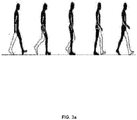
- the present invention relates to a method for estimating the movement of a walking pedestrian 1.
- what can define the movement is the overall movement of the pedestrian. This allows for example to follow its position on a map, to determine the distance traveled, etc., in particular for navigation without GPS, personal monitoring, etc.
- the pedestrian has at least one lower member 10 (ie a leg) equipped with inertial measurement means 20. It will be understood that each of the two lower members 10 of the pedestrian 1 can be equipped with inertial measurement means 20.
- the inertial measurement means 20 are integral with this lower limb 10, i.e. they have a substantially identical movement in the terrestrial frame of reference, we will see how later.
- the inertial measurement means are advantageously more precisely arranged in the so-called crural region of the lower leg 10, that is to say the lower half which extends between an ankle 12 and a knee 13 of the pedestrian (included), and generally any location having, when a distal end 11 of the lower limb 10 (ie the heel of the foot) is in contact with the ground (and advantageously permanently), substantially only a rotational movement relative to this distal end 11 of the lower limb 10, that is to say due to a lever arm.
- the means 20 can almost only rotate in the terrestrial frame of reference, and not a translation.
- the means 20 are typically arranged at the level of a tibia of the pedestrian 1, since by definition any point of the tibia is articulated with the foot only by the ankle 12, and therefore that their relative movement can only be a rotation, but we understand that they can also be on the thigh. Indeed, during a step, when the heel of the foot 11 is placed on the ground, the entire lower limb 10 is rigid (it is indeed physiologically necessary to stretch the leg on which one leans for a step, under penalty discomfort and ineffective walking). Due to this rigidity of the lower limb during this support phase, there is indeed a pure rotational movement between the points of the thigh and the distal end 11 of the limb 10.
- lever arm The distance between the point of rotation of the distal end 11 and the means 20 is called in the remainder of this description "lever arm”. And we note r the vector representing this lever arm oriented from the end 11 to the means 20.
- the inertial measurement means 20 are preferably those of a box 2 as shown in the figure 2 having means 23 for attachment to the lower limb 10.
- These attachment means 23 consist, for example, of a strap, for example with a hook-and-loop strap which encloses the member and allows the connection to be secured.
- the inertial measurement means 20 it is indeed desirable for the inertial measurement means 20 to be arranged as close as possible to the knee 13, and not to be able to move along the member 10.
- inertial measurement means 20 is meant an inertial unit comprising at least three accelerometers and three gyrometers arranged in triaxis.
- the gyrometers measure the instantaneous angular speed of the inertial unit with respect to the terrestrial reference system, noted ⁇ .
- Accelerometers are sensitive to external forces other than gravitational forces applied to the sensor, and make it possible to measure a noted acceleration ⁇ .
- the means 20 are advantageously accompanied by at least one magnetometer 24 so as to form means 20, 24 for magneto-inertial measurement.
- the magnetometer 24 measures a noted field B .
- Such a magnetometer 24 is useful for indicating a heading of the pedestrian (ie a direction in a horizontal plane), in particular at start-up since, as explained, the movement is relative.
- the magnetometer 24 is then no longer essential but can be used to readjust the heading which deviates following the accumulation of errors related to the angular speed measurements.
- the box 2 can comprise processing means 21 (typically a processor) for the direct implementation in real time of the treatments of the present method, or else the measurements can be transmitted via communication means 25 to an external device such as a mobile terminal (smartphone) 3, or even a remote server 4, or even the measurements can be recorded in local data storage means 22 (a memory for example of the flash type) local memory for an a posteriori processing for example on the waiter 4.
- processing means 21 typically a processor
- the measurements can be transmitted via communication means 25 to an external device such as a mobile terminal (smartphone) 3, or even a remote server 4, or even the measurements can be recorded in local data storage means 22 (a memory for example of the flash type) local memory for an a posteriori processing for example on the waiter 4.
- the communication means 25 can implement short-range wireless communication, for example Bluetooth or Wifi (in particular in one embodiment with a mobile terminal 3) or even be means of connection to a mobile network (typically UMTS / LTE ) for long distance communication. It should be noted that the communication means 25 may for example be a wired connection (typically USB) for transferring the data from the local data storage means 22 to those of a mobile terminal 3 or a server 4.
- short-range wireless communication for example Bluetooth or Wifi (in particular in one embodiment with a mobile terminal 3) or even be means of connection to a mobile network (typically UMTS / LTE ) for long distance communication.
- a mobile network typically UMTS / LTE
- the communication means 25 may for example be a wired connection (typically USB) for transferring the data from the local data storage means 22 to those of a mobile terminal 3 or a server 4.
- a mobile terminal 3 which hosts "intelligence"
- processing means 31 such as a processor for the implementation of the treatments of the present method which will be described.
- processing means 31 such as a processor for the implementation of the treatments of the present method which will be described.
- the processing means used are those of the case 2, the latter may also include communication means 25 for transmitting the estimated position.
- the position of the wearer can be sent to the mobile terminal 3 to display the position in an interface of navigation software.
- the method comprises the acquisition by the inertial measurement means 20 of the acceleration ⁇ and angular velocity ⁇ of said lower limb 10. It will be noted that in the following description, when mention is made of acceleration / speed / position of the lower limb 10, we mean at the level of the inertial measurement means 20.
- the orientation of the means 20 relative to the terrestrial inertial reference frame can be given for example by a rotation matrix (denoted R), an attitude quaternion (denoted q), the attitude is synonymous with orientation in space or Euler angles (roll ⁇ , pitch ⁇ , yaw ⁇ ). These three representations are equivalent, so we use them interchangeably in this document.
- the speed and the position of the means 20 are noted respectively v and d , and estimate themselves respectively by a simple and a double integration of the acceleration in the terrestrial frame of reference, which as we will see further on is calculated from the acceleration ⁇ measured (given in the mobile referential of the inertial measurement means 20) and of the orientation of the means 20 relative to the terrestrial reference (updated from the angular velocity measurements).
- the speed and the position of the means 20 relative to the terrestrial reference frame are initialized to zero.
- the initial position cannot be determined directly from accelerometer, gyrometer and magnetometer measurements, it can be provided by another sensor (for example GPS) or indicated by the user. We therefore know over time with the only inertial sensors (and if necessary magnetic) the relative position of the device 2 (and therefore of the pedestrian 1), defined with respect to the initial position.
- the terrestrial inertial frame of reference will be designated by the index i and the means frame of reference 20 also called body by the index b.
- the base change matrix from the terrestrial inertial reference frame to the central reference frame is denoted R i ⁇ b .
- R ⁇ n the estimation of this matrix after n no sample.
- Attitude is related to angular velocity ⁇ according to the differential equation on the passage matrix R i ⁇ b .
- the coordinates of ⁇ are expressed in the base of the inertial unit.
- R . i ⁇ b 0 - ⁇ bz ⁇ by ⁇ bz 0 - ⁇ bx - ⁇ by ⁇ bx 0 ⁇ R i ⁇ b
- R ⁇ not + 1 R ⁇ not + 0 - ⁇ z ⁇ there ⁇ z 0 - ⁇ x - ⁇ there ⁇ x 0 ⁇ R ⁇ not ⁇ dt
- the acceleration measurement is used.
- the method conventionally comprises a step (b) of estimating the speed as a function of said measured acceleration (in practice by integration) and a step (e) of estimating the movement as a function of the estimated speed (in practice also by integration).
- the covariance matrix is updated by linearizing the previous formulas around the current point.
- the present process cleverly uses the “foot on the ground” condition on which the ZUPT method is based, but without the need to have the sensor on the foot.
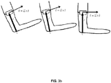
- the figure 3b this time represents a possible placement of the inertial measurement means 20 above the ankle 12 during the heel / ground contact phase.
- the inertial measurement means 20 rotate at least during this foot-to-ground phase, and therefore have an "expected speed" of the means 20 (ie of said lower limb 10) which will allow readjustment.
- a difficulty with respect to the ZUPT method is to arrive at determining a time interval of said walk of pedestrian 1 during which said distal end 11 of said lower member 10 is in contact with the ground, and more exactly the moment when the movement is pure rotation and the model giving the speed is correct.
- a step (c) makes it possible to determine this time interval of contact with the ground as a function of the acceleration measured, the angular speed measured, and the assumed or estimated lever arm. This explains why it is not essential that the means 20 have a substantially rotational movement relative to the distal end 11 of the lower limb 10 when it is not in contact with the ground.
- this step (c) comprises the calculation by the data processing means 21, 31, 41 of an "expected acceleration" as a function of said measured angular speed and of the lever arm.
- ⁇ att ⁇ - g ⁇ + d ⁇ ⁇ dt ⁇ r ⁇ + ⁇ ⁇ ⁇ ⁇ ⁇ r ⁇
- step (c) comprises the determination of the time interval of contact with the ground as a function of the acceleration measured and of said theoretical acceleration.
- the gravity field is known in the terrestrial frame of reference while the measurements of the gyrometer and the accelerometer as well as r are known in the base of the inertial unit.
- To calculate the vector difference it is therefore necessary to make a base change.
- we can compare the norms of the vectors difference ⁇ ⁇ - d ⁇ ⁇ dt ⁇ r ⁇ - ⁇ ⁇ ⁇ ⁇ ⁇ r ⁇ - g ⁇
- This difference is not in practice exactly zero and the period during which it is less than a predetermined threshold is selected, for example 10% of
- said time interval of said pedestrian walk 1 during which said distal end 11 of said lower limb 10 is in contact with the ground is determined in step (c) as that during which a difference between the measured acceleration and the theoretical acceleration is less than this predetermined threshold.
- a second embodiment which is not part of the present invention, it is possible to roughly search for the phase of contact with the ground on the basis of a characteristic pattern on the signal from the sensors.
- the rotation of the leg during rocking or the shock when the foot touches the ground for example can make it possible to determine approximately said contact interval with the ground.
- a characteristic duration for example a quarter of a second
- a step (d) allows the adjustment of the estimated speed.
- the expected speed of the lower limb 10 is calculated by the data processing means 21, 31, 41 as a function of said measured angular speed and of said lever arm.
- the estimated speed of said lower limb 10 is then corrected as a function of the expected speed.
- the length of the lever arm can be a constant entered by the user (if necessary after measurement).
- the method advantageously comprises a prior step (a0) for determining said lever arm.
- step (a0) can be implemented again (at regular intervals or on instructions from the pedestrian 1) when walking to redetermine r .
- a readjustment of r z is carried out as a function of the speed error measured at each phase of footing on the ground.
- this phase can be determined for example from the shock suffered when the foot touches the ground, or else it is a predetermined interval where the user knowingly places the foot in contact with the ground.
- the three coordinates of the lever arm can be added to the filter. The registration then concerns the three coordinates.
- the position of the means 20 on the lower limb 10 can also be estimated thanks to the complementary use of other sensors when they are available, for example a GPS giving a speed and the orientation of the power plant with respect to the earth, the unknown then being the lever arm, or even a vision system giving speed and orientation. Depending on the accuracy of the information compared to the exact speed at the sensor, a longer or shorter filtering time will be necessary.
- the figure 4a represents an example of a trajectory obtained after integration of the measurements of a box 2 carried above the ankle 12.
- the step consists of a round trip in a street with descent then climb of two stairs.
- the accelerometers and gyrometers used in the means 20 are precisely calibrated MEMS sensors.
- a extended Kalman filter was used with a recalibration using the lever arm model when the foot is on the ground as previously described.
- the figure 4b more precisely represents the descent and ascent of the stairs during the walk illustrated on the figure 4a .
- the height of the case 2 as a function of the distance traveled.
- Each stride on the flat is recognizable distinctly, the ankle 12 rising about 18 cm by performing a curved trajectory.
- the foot 11 crossing two steps and a height of about 30 cm.
- the marked distances of 128 m to 132 m we recognize for each stride the crossing of two steps.
- the latter is optimal for following the path of a pedestrian 1 in an area poorly or poorly covered by a GPS signal, inside buildings, in the basement, near high walls, in the forest, etc.
- the invention relates in particular to the equipment 2, 3, 4 for the implementation of one or the other of the embodiments of the method.
- the equipment is an autonomous box 2 comprising the means of inertial measurement 20 and the data processing means 21 configured for the implementation of the steps of the method.
- the case 2 further comprises means 23 for attaching the case 2 to the lower limb 10, and where appropriate a magnetometer 24, data storage means 22 (for storing the measured angular accelerations / velocities or estimated movements) and / or communication means 25 for exporting the results.
- the equipment is a mobile terminal 3 or a server 4, adapted to communicate with a box 2 comprising the inertial measurement means 20.
- the terminal 3 or the server 4 comprises the processing means 31 or 41 configured for the implementation of the steps of the method.
- Each box 2 can still include data processing means 21 for controlling the means 20 and the transmission (via communication means 25) of the measured data to the data processing means 31, 41.
- the means 21, 31, 41 can if necessary share the steps of the method.
- the processing means 21 of the box 2 can carry out the steps up to (e), and a posteriori the means 41 of the server 4 implement the step (f) of analysis so as to identify a possible disturbance in the walking of said pedestrian 1.
- the invention also relates in this case to the system comprising the equipment 3, 4 according to this embodiment and the box (es) 2 "satellites" in connection
- the invention relates to a computer program product comprising code instructions for the execution (on the processing means 21, 31, 41) of a method for estimating the movement of a pedestrian 1 in motion according to the first aspect of the invention, as well as storage means readable by computer equipment (for example data storage means 22) on which this computer program product is found.
Landscapes
- Engineering & Computer Science (AREA)
- Radar, Positioning & Navigation (AREA)
- Remote Sensing (AREA)
- Physics & Mathematics (AREA)
- General Physics & Mathematics (AREA)
- Automation & Control Theory (AREA)
- Measurement Of The Respiration, Hearing Ability, Form, And Blood Characteristics Of Living Organisms (AREA)
- Navigation (AREA)
Claims (15)
- Verfahren zum Schätzen der Bewegung eines gehenden Fußgängers (1), das Schritte umfasst des:(a) Messens einer Beschleunigung und einer Winkelgeschwindigkeit der unteren Extremität (10) durch Trägheitsmessmittel (20), die fest mit einer unteren Extremität (10) des Fußgängers (1) verbunden und so angeordnet sind, dass sie im Wesentlichen eine Drehbewegung in Bezug auf ein distales Ende (11) der unteren Extremität (10) mindestens dann aufweisen, wenn sich das distale Ende (11) der unteren Extremität (10) mit dem Boden in Kontakt befindet;(b) Schätzens einer Geschwindigkeit der unteren Extremität (10) durch Datenverarbeitungsmittel (21, 31, 41) in Abhängigkeit von der Beschleunigung und der Winkelgeschwindigkeit, die gemessen wurden;(c) Bestimmens eines Zeitintervalls des Gangs des Fußgängers (1), während dem sich das distale Ende (11) der unteren Extremität (10) mit dem Boden in Kontakt befindet, durch die Datenverarbeitungsmittel (21, 31, 41) in Abhängigkeit von der gemessenen Beschleunigung, der gemessenen Winkelgeschwindigkeit, und einem Hebelarm zwischen den Trägheitsmessmitteln (20) und dem distalen Ende (11);(d) in dem bestimmten Zeitintervall:∘ Berechnens einer erwarteten Geschwindigkeit der unteren Extremität (10) durch die Datenverarbeitungsmittel (21, 31, 41) in Abhängigkeit von der gemessenen Winkelgeschwindigkeit und dem Hebelarm;∘ Korrigierens der geschätzten Geschwindigkeit der unteren Extremität (10) in Abhängigkeit von der erwarteten Geschwindigkeit;(e) Schätzens der Bewegung des Fußgängers (1) durch die Datenverarbeitungsmittel (21, 31, 41) in Abhängigkeit von der korrigierten Geschwindigkeit der unteren Extremität (10).
- Verfahren nach Anspruch 1, wobei die Geschwindigkeit der unteren Extremität (10) durch Integration der gemessenen Beschleunigung, im terrestrischen Bezugssystem ausgedrückt, in Abhängigkeit von der gemessenen Winkelgeschwindigkeit geschätzt wird, und die Bewegung der unteren Extremität (10) durch Integration der geschätzten Geschwindigkeit geschätzt wird.
- Verfahren nach einem der Ansprüche 1 und 2, wobei die erwartete Geschwindigkeit durch die Formel
vatt =ω ∧r gegeben ist, wobeiω die gemessene Winkelgeschwindigkeit undr der Hebelarm ist. - Verfahren nach einem der Ansprüche 1 bis 3, wobei die Trägheitsmessmittel (20) zwischen einem Knöchel (12) und einem Knie (13) an der unteren Extremität (10) angeordnet sind.
- Verfahren nach einem der Ansprüche 1 bis 4, wobei der Schritt (c) das Berechnen einer erwarteten Beschleunigung durch die Datenverarbeitungsmittel (21, 31, 41) in Abhängigkeit von der gemessenen Winkelgeschwindigkeit und dem Hebelarm umfasst, wobei das Zeitintervall des Gangs des Fußgängers (1), während dem sich das distale Ende (11) der unteren Extremität (10) mit dem Boden in Kontakt befindet, in Abhängigkeit von der gemessenen Beschleunigung und der erwarteten Beschleunigung bestimmt wird.
- Verfahren nach Anspruch 5, wobei das Zeitintervall des Gangs des Fußgängers (1), während dem sich das distale Ende (11) der unteren Extremität (10) mit dem Boden in Kontakt befindet, im Schritt (c) als dasjenige bestimmt wird, während dem eine Abweichung zwischen der gemessenen Beschleunigung und der erwarteten Beschleunigung kleiner ist als eine vorbestimmte Schwelle.
- Verfahren nach einem der Ansprüche 5 und 6, wobei die erwartete Beschleunigung durch die Formel

ω die gemessene Winkelgeschwindigkeit,r der Hebelarm undg die Schwerebeschleunigung ist. - Verfahren nach einem der Ansprüche 1 bis 4, wobei das Zeitintervall des Gangs des Fußgängers (1), während dem sich das distale Ende (11) der unteren Extremität (10) mit dem Boden in Kontakt befindet, im Schritt (c) als dasjenige bestimmt wird, während oder nach dem die Beschleunigung und/oder die Winkelgeschwindigkeit, die gemessen wurden, einem vorbestimmten Muster entsprechen, das für den Kontakt des Endes (11) der unteren Extremität (10) repräsentativ ist.
- Verfahren nach einem der Ansprüche 1 bis 8, wobei das Korrigieren einer geschätzten Geschwindigkeit der unteren Extremität (10) im Schritt (c) das Implementieren eines linearen oder nichtlinearen Zustandsschätzfilters umfasst.
- Verfahren nach einem der Ansprüche 1 bis 9, das einen vorausgehenden Schritt (a0) des Bestimmens des Hebelarms umfasst.
- Verfahren nach Anspruch 10, wobei der Hebelarm unter Minimieren der Abweichung zwischen der gemessenen Beschleunigung und einer erwarteten Beschleunigung, die von der gemessenen Winkelgeschwindigkeit und dem Hebelarm abhängig ist, während eines vorbestimmten Zeitintervalls des Gangs des Fußgängers (1) bestimmt wird, während dem sich das distale Ende (11) der unteren Extremität (10) mit dem Boden in Kontakt befindet.
- Verfahren nach den Ansprüchen 9 und 10 in Kombination, wobei das Bestimmen des Hebelarms die Integration des Hebelarms in den Filter umfasst.
- Ausrüstung (2, 3, 4) zum Schätzen der Bewegung eines gehenden Fußgängers (1), die Datenverarbeitungsmittel (21, 31, 41) umfasst, die dafür konfiguriert sind, zu implementieren:- ein Modul zum Empfangen einer Beschleunigung und einer Winkelgeschwindigkeit einer unteren Extremität (10) des Fußgängers (1), die durch Trägheitsmessmittel (20) gemessen werden, welche fest mit der unteren Extremität (10) verbunden und so angeordnet sind, dass sie im Wesentlichen eine Drehbewegung in Bezug auf ein distales Ende (11) der unteren Extremität (10) mindestens dann aufweisen, wenn sich das distale Ende (11) der unteren Extremität (10) mit dem Boden in Kontakt befindet;- ein Modul zum Schätzen einer Geschwindigkeit der unteren Extremität (10) in Abhängigkeit von der Beschleunigung und der Winkelgeschwindigkeit, die gemessen wurden;- ein Modul zum Bestimmen eines Zeitintervalls des Gangs des Fußgängers (1), während dem sich das distale Ende (11) der unteren Extremität (10) mit dem Boden in Kontakt befindet, in Abhängigkeit von der gemessenen Beschleunigung, der gemessenen Winkelgeschwindigkeit, und einem Hebelarm zwischen den Trägheitsmessmitteln (20) und dem distalen Ende (11);- ein Modul zum Berechnen, in dem bestimmten Zeitintervall, einer erwarteten Geschwindigkeit der unteren Extremität (10) in Abhängigkeit von der gemessenen Winkelgeschwindigkeit und dem Hebelarm;- ein Modul zum Korrigieren, in dem Zeitintervall, der geschätzten Geschwindigkeit der unteren Extremität (10) in Abhängigkeit von der erwarteten Geschwindigkeit;- ein Modul zum Schätzen der Bewegung des Fußgängers (1) in Abhängigkeit von der korrigierten Geschwindigkeit der unteren Extremität (10).
- Computerprogrammprodukt, das Codeanweisungen umfasst für das Ausführen eines Verfahrens zum Schätzen der Bewegung eines gehenden Fußgängers (1) nach einem der Ansprüche 1 bis 12, wenn das Programm auf einem Computer ausgeführt wird.
- Speichermittel, das von einer IT-Ausrüstung gelesen werden kann, auf dem ein Computerprogrammprodukt Codeanweisungen für das Ausführen eines Verfahrens zum Schätzen der Bewegung eines gehenden Fußgängers (1) nach einem der Ansprüche 1 bis 12 umfasst.
Applications Claiming Priority (2)
| Application Number | Priority Date | Filing Date | Title |
|---|---|---|---|
| FR1559591A FR3042266B1 (fr) | 2015-10-08 | 2015-10-08 | Procede d'estimation du mouvement d'un pieton |
| PCT/FR2016/052619 WO2017060660A1 (fr) | 2015-10-08 | 2016-10-10 | Procédé d'estimation du mouvement d'un piéton |
Publications (2)
| Publication Number | Publication Date |
|---|---|
| EP3359915A1 EP3359915A1 (de) | 2018-08-15 |
| EP3359915B1 true EP3359915B1 (de) | 2019-12-25 |
Family
ID=55542748
Family Applications (1)
| Application Number | Title | Priority Date | Filing Date |
|---|---|---|---|
| EP16793957.8A Active EP3359915B1 (de) | 2015-10-08 | 2016-10-10 | Verfahren zur schätzung der bewegung eines fussgängers |
Country Status (6)
| Country | Link |
|---|---|
| US (1) | US11099029B2 (de) |
| EP (1) | EP3359915B1 (de) |
| JP (1) | JP7023234B2 (de) |
| ES (1) | ES2779764T3 (de) |
| FR (1) | FR3042266B1 (de) |
| WO (1) | WO2017060660A1 (de) |
Families Citing this family (12)
| Publication number | Priority date | Publication date | Assignee | Title |
|---|---|---|---|---|
| US9877668B1 (en) * | 2014-11-21 | 2018-01-30 | University Of South Florida | Orientation invariant gait matching |
| FR3047070B1 (fr) | 2016-01-27 | 2021-09-24 | Sysnav | Procede d'estimation de l'activite physique d'un membre superieur |
| FR3069316B1 (fr) * | 2017-07-21 | 2019-08-16 | Sysnav | Procede d'estimation du mouvement d'un objet evoluant dans un champ magnetique |
| KR102581198B1 (ko) * | 2018-04-16 | 2023-09-22 | 한국전자통신연구원 | 신발 모델을 이용한 보행 항법 장치 및 그 방법 |
| FR3082722B1 (fr) | 2018-06-21 | 2020-09-25 | Sysnav | Procede d'analyse de foulee d'un pieton en marche |
| US11109192B2 (en) | 2018-09-12 | 2021-08-31 | Apple Inc. | User-specific motion model for location estimation |
| CN110579212B (zh) * | 2019-08-13 | 2022-11-29 | 湘潭大学 | 室内定位方法及装置 |
| IT201900024045A1 (it) * | 2019-12-16 | 2021-06-16 | Davide Marzotto | Dispositivo per il tracciamento della posizione in ambiente subacqueo o sotterraneo. |
| FR3120939A1 (fr) * | 2021-03-18 | 2022-09-23 | Continental Automotive | Procede de determination de la position d’un equipement portable par rapport a un vehicule automobile et equipement portable associe |
| KR102639232B1 (ko) * | 2021-06-02 | 2024-02-21 | 인하대학교 산학협력단 | 가속도 센서를 이용한 정확도 높은 보행속도 측정 방법 및 시스템 |
| CN114279441B (zh) * | 2021-12-15 | 2023-12-29 | 中国科学院深圳先进技术研究院 | 一种零速区间检测方法、行人导航系统及存储介质 |
| FR3137764A1 (fr) | 2022-07-08 | 2024-01-12 | Sysnav | Procédé de recalage d’une attitude fournie par un système de navigation à l’estime au moyen d’un système de positionnement relatif |
Family Cites Families (7)
| Publication number | Priority date | Publication date | Assignee | Title |
|---|---|---|---|---|
| GB9916482D0 (en) * | 1999-07-15 | 1999-09-15 | British Aerospace | Terrain navigation apparatus for a legged animal traversing terrain |
| PT103933A (pt) | 2008-01-17 | 2009-07-17 | Univ Do Porto | Dispositivo portátil e método para medição e cálculo de parâmetros dinâmicos da locomoção pedestre |
| US8224575B2 (en) * | 2008-04-08 | 2012-07-17 | Ensco, Inc. | Method and computer-readable storage medium with instructions for processing data in an internal navigation system |
| EP2593009B1 (de) | 2010-07-14 | 2020-08-26 | Ecole Polytechnique Federale De Lausanne (Epfl) | System und verfahren zur 3d-untersuchung von gehbewegungen |
| WO2012072961A2 (fr) * | 2010-12-01 | 2012-06-07 | Commissariat à l'énergie atomique et aux énergies alternatives | Procede et systeme de determination de valeurs de parametres representatifs d'un mouvement d'au moins deux membres d'une entite representee sous la forme d'une chaine articulee |
| US20130131555A1 (en) * | 2011-11-17 | 2013-05-23 | William R. Hook | Gait analysis using angular rate reversal |
| US9288298B2 (en) * | 2014-05-06 | 2016-03-15 | Fitbit, Inc. | Notifications regarding interesting or unusual activity detected from an activity monitoring device |
-
2015
- 2015-10-08 FR FR1559591A patent/FR3042266B1/fr active Active
-
2016
- 2016-10-10 JP JP2018537731A patent/JP7023234B2/ja active Active
- 2016-10-10 WO PCT/FR2016/052619 patent/WO2017060660A1/fr active Application Filing
- 2016-10-10 EP EP16793957.8A patent/EP3359915B1/de active Active
- 2016-10-10 US US15/766,296 patent/US11099029B2/en active Active
- 2016-10-10 ES ES16793957T patent/ES2779764T3/es active Active
Non-Patent Citations (1)
| Title |
|---|
| None * |
Also Published As
| Publication number | Publication date |
|---|---|
| FR3042266A1 (fr) | 2017-04-14 |
| EP3359915A1 (de) | 2018-08-15 |
| US20180292230A1 (en) | 2018-10-11 |
| JP2018536869A (ja) | 2018-12-13 |
| ES2779764T3 (es) | 2020-08-19 |
| US11099029B2 (en) | 2021-08-24 |
| WO2017060660A1 (fr) | 2017-04-13 |
| FR3042266B1 (fr) | 2019-04-19 |
| JP7023234B2 (ja) | 2022-02-21 |
Similar Documents
| Publication | Publication Date | Title |
|---|---|---|
| EP3359915B1 (de) | Verfahren zur schätzung der bewegung eines fussgängers | |
| EP2646775B1 (de) | Verfahren und system zur schätzung des weges eines mobilen elements oder körpers | |
| EP2646776B1 (de) | Verfahren und system zur bestimmung der werte der charakteristischen parameter einer bewegung von mindestens zwei gliedmassen einer einheit in form einer gelenkigen leitung | |
| EP2350565B1 (de) | Einrichtung und verfahren zum bestimmen eines charakteristikums eines durch aufeinanderfolgende positionen eines starr mit einem mobilen element verbundenen triaxialbeschleunigungsmessers gebildeten pfads | |
| FR3012597B1 (fr) | Procede de localisation en interieur et exterieur et dispositif portatif mettant en œuvre un tel procede | |
| EP2560551B1 (de) | System zur analyse der fortschritte eines benutzers | |
| EP2245479B1 (de) | Navigationssystem mit phasenmessungshybridisierung | |
| WO2015091402A1 (fr) | Procede de determination de l'orientation d'un repere capteur lie a un terminal mobile muni d'un ensemble capteur, porte par un utilisateur et comprenant au moins un capteur de mouvement lie en mouvement | |
| EP3447654B1 (de) | Bestimmungsverfahren der bewegungsbahn eines beweglichen objekts, programm und vorrichtung zur umsetzung dieses verfahrens | |
| FR3064350A1 (fr) | Procede de calcul d'une vitesse d'un aeronef, procede de calcul d'un rayon de protection, systeme de positionnement et aeronef associes | |
| EP3408612B1 (de) | Verfahren zur kalkulation der physischen aktivität einer oberen gliedmasse | |
| KR102581198B1 (ko) | 신발 모델을 이용한 보행 항법 장치 및 그 방법 | |
| EP3807595A1 (de) | Verfahren zum kalibrieren eines in einem objekt eingebauten gyrometers | |
| FR3109212A1 (fr) | Procede d’identification d’une phase statique d’un vehicule | |
| EP3655725A1 (de) | Verfahren zur schätzung der bewegung eines objekts, das sich in einer magnetfeldumgebung beweget | |
| EP3658852A1 (de) | Bestimmung eines steuerkurses unter verwendung eines durch magnetische sensoren gemessenen feldes | |
| FR2939191A1 (fr) | Dispositif et procede d'assistance au guidage d'un pieton en difficulte de perception visuelle, telle qu'une personne aveugle | |
| WO2024009048A1 (fr) | Procede de recalage d'une attitude fournie par un systeme de navigation a l'estime au moyen d'un systeme de positionnement relatif | |
| FR3041769A1 (fr) | Procede de geolocalisation | |
| FR2968395A1 (fr) | Systeme d'estimation d'une trajectoire | |
| CH707379B1 (fr) | Procédé de calcul de distance et podomètre associé. |
Legal Events
| Date | Code | Title | Description |
|---|---|---|---|
| STAA | Information on the status of an ep patent application or granted ep patent |
Free format text: STATUS: UNKNOWN |
|
| STAA | Information on the status of an ep patent application or granted ep patent |
Free format text: STATUS: THE INTERNATIONAL PUBLICATION HAS BEEN MADE |
|
| PUAI | Public reference made under article 153(3) epc to a published international application that has entered the european phase |
Free format text: ORIGINAL CODE: 0009012 |
|
| STAA | Information on the status of an ep patent application or granted ep patent |
Free format text: STATUS: REQUEST FOR EXAMINATION WAS MADE |
|
| 17P | Request for examination filed |
Effective date: 20180504 |
|
| AK | Designated contracting states |
Kind code of ref document: A1 Designated state(s): AL AT BE BG CH CY CZ DE DK EE ES FI FR GB GR HR HU IE IS IT LI LT LU LV MC MK MT NL NO PL PT RO RS SE SI SK SM TR |
|
| AX | Request for extension of the european patent |
Extension state: BA ME |
|
| DAV | Request for validation of the european patent (deleted) | ||
| DAX | Request for extension of the european patent (deleted) | ||
| GRAP | Despatch of communication of intention to grant a patent |
Free format text: ORIGINAL CODE: EPIDOSNIGR1 |
|
| STAA | Information on the status of an ep patent application or granted ep patent |
Free format text: STATUS: GRANT OF PATENT IS INTENDED |
|
| INTG | Intention to grant announced |
Effective date: 20190826 |
|
| GRAS | Grant fee paid |
Free format text: ORIGINAL CODE: EPIDOSNIGR3 |
|
| GRAA | (expected) grant |
Free format text: ORIGINAL CODE: 0009210 |
|
| STAA | Information on the status of an ep patent application or granted ep patent |
Free format text: STATUS: THE PATENT HAS BEEN GRANTED |
|
| AK | Designated contracting states |
Kind code of ref document: B1 Designated state(s): AL AT BE BG CH CY CZ DE DK EE ES FI FR GB GR HR HU IE IS IT LI LT LU LV MC MK MT NL NO PL PT RO RS SE SI SK SM TR |
|
| REG | Reference to a national code |
Ref country code: GB Ref legal event code: FG4D Free format text: NOT ENGLISH |
|
| REG | Reference to a national code |
Ref country code: CH Ref legal event code: EP |
|
| REG | Reference to a national code |
Ref country code: AT Ref legal event code: REF Ref document number: 1217602 Country of ref document: AT Kind code of ref document: T Effective date: 20200115 |
|
| REG | Reference to a national code |
Ref country code: DE Ref legal event code: R096 Ref document number: 602016026978 Country of ref document: DE |
|
| REG | Reference to a national code |
Ref country code: IE Ref legal event code: FG4D Free format text: LANGUAGE OF EP DOCUMENT: FRENCH |
|
| REG | Reference to a national code |
Ref country code: NL Ref legal event code: MP Effective date: 20191225 |
|
| PG25 | Lapsed in a contracting state [announced via postgrant information from national office to epo] |
Ref country code: LT Free format text: LAPSE BECAUSE OF FAILURE TO SUBMIT A TRANSLATION OF THE DESCRIPTION OR TO PAY THE FEE WITHIN THE PRESCRIBED TIME-LIMIT Effective date: 20191225 Ref country code: SE Free format text: LAPSE BECAUSE OF FAILURE TO SUBMIT A TRANSLATION OF THE DESCRIPTION OR TO PAY THE FEE WITHIN THE PRESCRIBED TIME-LIMIT Effective date: 20191225 Ref country code: NO Free format text: LAPSE BECAUSE OF FAILURE TO SUBMIT A TRANSLATION OF THE DESCRIPTION OR TO PAY THE FEE WITHIN THE PRESCRIBED TIME-LIMIT Effective date: 20200325 Ref country code: LV Free format text: LAPSE BECAUSE OF FAILURE TO SUBMIT A TRANSLATION OF THE DESCRIPTION OR TO PAY THE FEE WITHIN THE PRESCRIBED TIME-LIMIT Effective date: 20191225 Ref country code: GR Free format text: LAPSE BECAUSE OF FAILURE TO SUBMIT A TRANSLATION OF THE DESCRIPTION OR TO PAY THE FEE WITHIN THE PRESCRIBED TIME-LIMIT Effective date: 20200326 Ref country code: FI Free format text: LAPSE BECAUSE OF FAILURE TO SUBMIT A TRANSLATION OF THE DESCRIPTION OR TO PAY THE FEE WITHIN THE PRESCRIBED TIME-LIMIT Effective date: 20191225 Ref country code: BG Free format text: LAPSE BECAUSE OF FAILURE TO SUBMIT A TRANSLATION OF THE DESCRIPTION OR TO PAY THE FEE WITHIN THE PRESCRIBED TIME-LIMIT Effective date: 20200325 |
|
| REG | Reference to a national code |
Ref country code: LT Ref legal event code: MG4D |
|
| PG25 | Lapsed in a contracting state [announced via postgrant information from national office to epo] |
Ref country code: RS Free format text: LAPSE BECAUSE OF FAILURE TO SUBMIT A TRANSLATION OF THE DESCRIPTION OR TO PAY THE FEE WITHIN THE PRESCRIBED TIME-LIMIT Effective date: 20191225 Ref country code: HR Free format text: LAPSE BECAUSE OF FAILURE TO SUBMIT A TRANSLATION OF THE DESCRIPTION OR TO PAY THE FEE WITHIN THE PRESCRIBED TIME-LIMIT Effective date: 20191225 |
|
| PG25 | Lapsed in a contracting state [announced via postgrant information from national office to epo] |
Ref country code: AL Free format text: LAPSE BECAUSE OF FAILURE TO SUBMIT A TRANSLATION OF THE DESCRIPTION OR TO PAY THE FEE WITHIN THE PRESCRIBED TIME-LIMIT Effective date: 20191225 |
|
| PG25 | Lapsed in a contracting state [announced via postgrant information from national office to epo] |
Ref country code: PT Free format text: LAPSE BECAUSE OF FAILURE TO SUBMIT A TRANSLATION OF THE DESCRIPTION OR TO PAY THE FEE WITHIN THE PRESCRIBED TIME-LIMIT Effective date: 20200520 Ref country code: EE Free format text: LAPSE BECAUSE OF FAILURE TO SUBMIT A TRANSLATION OF THE DESCRIPTION OR TO PAY THE FEE WITHIN THE PRESCRIBED TIME-LIMIT Effective date: 20191225 Ref country code: RO Free format text: LAPSE BECAUSE OF FAILURE TO SUBMIT A TRANSLATION OF THE DESCRIPTION OR TO PAY THE FEE WITHIN THE PRESCRIBED TIME-LIMIT Effective date: 20191225 Ref country code: NL Free format text: LAPSE BECAUSE OF FAILURE TO SUBMIT A TRANSLATION OF THE DESCRIPTION OR TO PAY THE FEE WITHIN THE PRESCRIBED TIME-LIMIT Effective date: 20191225 Ref country code: CZ Free format text: LAPSE BECAUSE OF FAILURE TO SUBMIT A TRANSLATION OF THE DESCRIPTION OR TO PAY THE FEE WITHIN THE PRESCRIBED TIME-LIMIT Effective date: 20191225 |
|
| REG | Reference to a national code |
Ref country code: ES Ref legal event code: FG2A Ref document number: 2779764 Country of ref document: ES Kind code of ref document: T3 Effective date: 20200819 |
|
| PG25 | Lapsed in a contracting state [announced via postgrant information from national office to epo] |
Ref country code: IS Free format text: LAPSE BECAUSE OF FAILURE TO SUBMIT A TRANSLATION OF THE DESCRIPTION OR TO PAY THE FEE WITHIN THE PRESCRIBED TIME-LIMIT Effective date: 20200425 Ref country code: SK Free format text: LAPSE BECAUSE OF FAILURE TO SUBMIT A TRANSLATION OF THE DESCRIPTION OR TO PAY THE FEE WITHIN THE PRESCRIBED TIME-LIMIT Effective date: 20191225 Ref country code: SM Free format text: LAPSE BECAUSE OF FAILURE TO SUBMIT A TRANSLATION OF THE DESCRIPTION OR TO PAY THE FEE WITHIN THE PRESCRIBED TIME-LIMIT Effective date: 20191225 |
|
| REG | Reference to a national code |
Ref country code: DE Ref legal event code: R097 Ref document number: 602016026978 Country of ref document: DE |
|
| PG25 | Lapsed in a contracting state [announced via postgrant information from national office to epo] |
Ref country code: DK Free format text: LAPSE BECAUSE OF FAILURE TO SUBMIT A TRANSLATION OF THE DESCRIPTION OR TO PAY THE FEE WITHIN THE PRESCRIBED TIME-LIMIT Effective date: 20191225 |
|
| PLBE | No opposition filed within time limit |
Free format text: ORIGINAL CODE: 0009261 |
|
| STAA | Information on the status of an ep patent application or granted ep patent |
Free format text: STATUS: NO OPPOSITION FILED WITHIN TIME LIMIT |
|
| REG | Reference to a national code |
Ref country code: AT Ref legal event code: MK05 Ref document number: 1217602 Country of ref document: AT Kind code of ref document: T Effective date: 20191225 |
|
| PG25 | Lapsed in a contracting state [announced via postgrant information from national office to epo] |
Ref country code: SI Free format text: LAPSE BECAUSE OF FAILURE TO SUBMIT A TRANSLATION OF THE DESCRIPTION OR TO PAY THE FEE WITHIN THE PRESCRIBED TIME-LIMIT Effective date: 20191225 |
|
| 26N | No opposition filed |
Effective date: 20200928 |
|
| PG25 | Lapsed in a contracting state [announced via postgrant information from national office to epo] |
Ref country code: AT Free format text: LAPSE BECAUSE OF FAILURE TO SUBMIT A TRANSLATION OF THE DESCRIPTION OR TO PAY THE FEE WITHIN THE PRESCRIBED TIME-LIMIT Effective date: 20191225 |
|
| PG25 | Lapsed in a contracting state [announced via postgrant information from national office to epo] |
Ref country code: PL Free format text: LAPSE BECAUSE OF FAILURE TO SUBMIT A TRANSLATION OF THE DESCRIPTION OR TO PAY THE FEE WITHIN THE PRESCRIBED TIME-LIMIT Effective date: 20191225 |
|
| REG | Reference to a national code |
Ref country code: CH Ref legal event code: PL |
|
| PG25 | Lapsed in a contracting state [announced via postgrant information from national office to epo] |
Ref country code: LU Free format text: LAPSE BECAUSE OF NON-PAYMENT OF DUE FEES Effective date: 20201010 Ref country code: MC Free format text: LAPSE BECAUSE OF FAILURE TO SUBMIT A TRANSLATION OF THE DESCRIPTION OR TO PAY THE FEE WITHIN THE PRESCRIBED TIME-LIMIT Effective date: 20191225 |
|
| REG | Reference to a national code |
Ref country code: BE Ref legal event code: MM Effective date: 20201031 |
|
| PG25 | Lapsed in a contracting state [announced via postgrant information from national office to epo] |
Ref country code: CH Free format text: LAPSE BECAUSE OF NON-PAYMENT OF DUE FEES Effective date: 20201031 Ref country code: BE Free format text: LAPSE BECAUSE OF NON-PAYMENT OF DUE FEES Effective date: 20201031 Ref country code: LI Free format text: LAPSE BECAUSE OF NON-PAYMENT OF DUE FEES Effective date: 20201031 |
|
| PG25 | Lapsed in a contracting state [announced via postgrant information from national office to epo] |
Ref country code: IE Free format text: LAPSE BECAUSE OF NON-PAYMENT OF DUE FEES Effective date: 20201010 |
|
| PG25 | Lapsed in a contracting state [announced via postgrant information from national office to epo] |
Ref country code: TR Free format text: LAPSE BECAUSE OF FAILURE TO SUBMIT A TRANSLATION OF THE DESCRIPTION OR TO PAY THE FEE WITHIN THE PRESCRIBED TIME-LIMIT Effective date: 20191225 Ref country code: MT Free format text: LAPSE BECAUSE OF FAILURE TO SUBMIT A TRANSLATION OF THE DESCRIPTION OR TO PAY THE FEE WITHIN THE PRESCRIBED TIME-LIMIT Effective date: 20191225 Ref country code: CY Free format text: LAPSE BECAUSE OF FAILURE TO SUBMIT A TRANSLATION OF THE DESCRIPTION OR TO PAY THE FEE WITHIN THE PRESCRIBED TIME-LIMIT Effective date: 20191225 |
|
| PG25 | Lapsed in a contracting state [announced via postgrant information from national office to epo] |
Ref country code: MK Free format text: LAPSE BECAUSE OF FAILURE TO SUBMIT A TRANSLATION OF THE DESCRIPTION OR TO PAY THE FEE WITHIN THE PRESCRIBED TIME-LIMIT Effective date: 20191225 |
|
| PGFP | Annual fee paid to national office [announced via postgrant information from national office to epo] |
Ref country code: FR Payment date: 20230913 Year of fee payment: 8 |
|
| PGFP | Annual fee paid to national office [announced via postgrant information from national office to epo] |
Ref country code: GB Payment date: 20231019 Year of fee payment: 8 |
|
| PGFP | Annual fee paid to national office [announced via postgrant information from national office to epo] |
Ref country code: ES Payment date: 20231114 Year of fee payment: 8 |
|
| PGFP | Annual fee paid to national office [announced via postgrant information from national office to epo] |
Ref country code: IT Payment date: 20231010 Year of fee payment: 8 Ref country code: DE Payment date: 20231011 Year of fee payment: 8 |