EP2349831B1 - Arrangement for adjusting an aircraft propeller - Google Patents
Arrangement for adjusting an aircraft propeller Download PDFInfo
- Publication number
- EP2349831B1 EP2349831B1 EP20090782475 EP09782475A EP2349831B1 EP 2349831 B1 EP2349831 B1 EP 2349831B1 EP 20090782475 EP20090782475 EP 20090782475 EP 09782475 A EP09782475 A EP 09782475A EP 2349831 B1 EP2349831 B1 EP 2349831B1
- Authority
- EP
- European Patent Office
- Prior art keywords
- hydraulic
- pressure
- pump
- propeller
- hydraulic pump
- Prior art date
- Legal status (The legal status is an assumption and is not a legal conclusion. Google has not performed a legal analysis and makes no representation as to the accuracy of the status listed.)
- Not-in-force
Links
Images
Classifications
-
- B—PERFORMING OPERATIONS; TRANSPORTING
- B64—AIRCRAFT; AVIATION; COSMONAUTICS
- B64C—AEROPLANES; HELICOPTERS
- B64C11/00—Propellers, e.g. of ducted type; Features common to propellers and rotors for rotorcraft
- B64C11/30—Blade pitch-changing mechanisms
- B64C11/38—Blade pitch-changing mechanisms fluid, e.g. hydraulic
-
- Y—GENERAL TAGGING OF NEW TECHNOLOGICAL DEVELOPMENTS; GENERAL TAGGING OF CROSS-SECTIONAL TECHNOLOGIES SPANNING OVER SEVERAL SECTIONS OF THE IPC; TECHNICAL SUBJECTS COVERED BY FORMER USPC CROSS-REFERENCE ART COLLECTIONS [XRACs] AND DIGESTS
- Y10—TECHNICAL SUBJECTS COVERED BY FORMER USPC
- Y10T—TECHNICAL SUBJECTS COVERED BY FORMER US CLASSIFICATION
- Y10T137/00—Fluid handling
- Y10T137/8593—Systems
- Y10T137/85978—With pump
- Y10T137/85986—Pumped fluid control
- Y10T137/86002—Fluid pressure responsive
- Y10T137/86019—Direct response valve
Definitions
- the invention relates to an arrangement for the hydraulic adjustment of the propeller blades of an aircraft propeller with a hydraulic cylinder connected via a pressure relief valve to a hydraulic pump.
- propellers In aviation, it is known to use propellers with adjustable propeller blades (pitch propellers) whose pitch can be adjusted in this way to different operating situations, especially during takeoff and landing and when maneuvering on the airfield.
- pitch propellers In a known arrangement for adjusting the propeller blades, these are connected via an adjusting mechanism to the piston actuated in a hydraulic cylinder by the energy of a hydraulic fluid.
- the hydraulic fluid is provided with a constant volume and a certain pressure via a pressure line from a suction side to a hydraulic fluid reservoir, such as an oil reservoir or the transmission housing, connected hydraulic pump.
- a pressure relief valve and a propeller control hydraulics In the pressure line, a pressure relief valve and a propeller control hydraulics are involved.
- the pressure relief valve limits the pressure to a constant maximum target pressure by opening the pressure limiting valve when the setpoint pressure is exceeded and excess hydraulic fluid supplied by the hydraulic pump returns via a return line into the oil reservoir until the target pressure has fallen below.
- the invention has for its object to further develop the initially mentioned arrangement for the hydraulic adjustment of the propeller blades of an aircraft propeller so that the efficiency of the hydraulic system is improved.
- the basic idea of the invention consists in the return of the oil volume diverted at the pressure limiting valve to set a constant pressure acting on the hydraulic cylinder by the shortest route into the hydraulic oil circuit by the pressure limiting valve being arranged parallel to the hydraulic pump and directly connected to its pressure connection and its suction connection.
- the pressure relief valve and the corresponding connecting lines to the pressure and suction port of the hydraulic pump are integrated into the pump housing, so that the branched off for setpoint adjustment oil actually covers the shortest path and also a compact design is possible.
- the hydraulic pump is a gear pump, preferably an external gear pump.
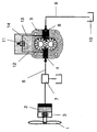
- the pitch of an aircraft propeller 1 is adjusted by means of a single-acting, on one side of the hydraulic piston 2 with hydraulic oil (hydraulic fluid) acted upon hydraulic cylinder 3.
- the supply of hydraulic oil to the hydraulic cylinder 3 takes place from the pressure port 4 of a trained as external gear pump hydraulic pump 5 via a pressure line 6 and a connected thereto propeller control hydraulics 7.
- the suction port 8 of the hydraulic pump 5 is via a suction line 9 to a hydraulic fluid reservoir 10, here an oil reservoir or a transmission housing, connected.
- the hydraulic pump 5 generates a continuous volume flow of the hydraulic oil, which reaches the hydraulic cylinder 3 under pressure.
- a for limiting a certain maximum, acting on the hydraulic cylinder 3 target pressure relief valve 11 is arranged in parallel and in close proximity to the hydraulic pump 5 and connected via a short auxiliary pressure line 12 directly to the pressure port 4 and a short return line 13 directly to the suction port 8 of the hydraulic pump 5 ,
- the pressure relief valve 11 is integrated in the pump housing 14 of the hydraulic pump 5, so that the hydraulic oil branched off to limit the pressure only has to travel very short distances.
Description
Die Erfindung betrifft eine Anordnung zum hydraulischen Verstellen der Propellerblätter eines Flugzeugpropellers mit einem über ein Druckbegrenzungsventil an eine Hydraulikpumpe angeschlossenen Hydraulikzylinder.The invention relates to an arrangement for the hydraulic adjustment of the propeller blades of an aircraft propeller with a hydraulic cylinder connected via a pressure relief valve to a hydraulic pump.
In der Luftfahrt werden bekanntermaßen Propeller mit einstellbaren Propellerblättern (Verstellpropeller) eingesetzt, deren Anstellwinkel auf diese Weise an verschiedene Betriebssituationen, insbesondere beim Start und bei der Landung und beim Rangieren auf dem Flugfeld, angepasst werden kann. Bei einer bekannten Anordnung zum Verstellen der Propellerblätter stehen diese über einen Stellmechanismus mit dem in einem Hydraulikzylinder durch die Energie einer Hydraulikflüssigkeit betätigten Kolbens in Verbindung. Die Hydraulikflüssigkeit wird mit konstantem Volumen und einem bestimmten Druck über eine Druckleitung von einer saugseitig an ein Hydraulikflüssigkeitsreservoir, beispielsweise einen Ölbehälter oder das Getriebegehäuse, angeschlossenen Hydraulikpumpe bereitgestellt. In die Druckleitung sind ein Druckbegrenzungsventil und eine Propeller-Regelhydraulik eingebunden. Das Druckbegrenzungsventil begrenzt den Druck auf einen konstanten maximalen Solldruck, indem das Druckbegrenzungsventil beim Überschreiten des Solldrucks solange öffnet und von der Hydraulikpumpe zugeführte überschüssige Hydraulikflüssigkeit über eine Rücklaufleitung in den Ölbehälter zurückführt bis der Solldruck unterschritten ist. Im praktischen Betrieb besteht somit ein ständiger Hydraulikflüssigkeitskreislauf vom Ölbehälter über die Saugleitung, die Hydraulikpumpe, die Druckleitung, das Druckbegrenzungsventil und die lange Rücklaufleitung zurück zum Ölbehälter. Infolge des ständigen Ölkreislaufs über eine lange Wegstrecke ergeben sich Strömungsverluste und eine damit verbundene Erwärmung des Öls und letztlich eine Verminderung des Wirkungsgrades des gesamten hydraulischen Systems.In aviation, it is known to use propellers with adjustable propeller blades (pitch propellers) whose pitch can be adjusted in this way to different operating situations, especially during takeoff and landing and when maneuvering on the airfield. In a known arrangement for adjusting the propeller blades, these are connected via an adjusting mechanism to the piston actuated in a hydraulic cylinder by the energy of a hydraulic fluid. The hydraulic fluid is provided with a constant volume and a certain pressure via a pressure line from a suction side to a hydraulic fluid reservoir, such as an oil reservoir or the transmission housing, connected hydraulic pump. In the pressure line, a pressure relief valve and a propeller control hydraulics are involved. The pressure relief valve limits the pressure to a constant maximum target pressure by opening the pressure limiting valve when the setpoint pressure is exceeded and excess hydraulic fluid supplied by the hydraulic pump returns via a return line into the oil reservoir until the target pressure has fallen below. In practical operation, there is thus a constant hydraulic fluid circuit from the oil reservoir via the suction line, the hydraulic pump, the pressure line, the pressure relief valve and the long return line back to the oil reservoir. As a result of the constant oil circulation Over a long distance, there are flow losses and associated heating of the oil and ultimately a reduction in the efficiency of the entire hydraulic system.
Ein wesentlicher Stand der Technik ist durch
Der Erfindung liegt die Aufgabe zugrunde, die eingangs erwähnte Anordnung zur hydraulischen Verstellung der Propellerblätter eines Flugzeugpropellers so weiterzuentwickeln, dass der Wirkungsgrad des hydraulischen Systems verbessert wird.The invention has for its object to further develop the initially mentioned arrangement for the hydraulic adjustment of the propeller blades of an aircraft propeller so that the efficiency of the hydraulic system is improved.
Erfindungsgemäß wird die Aufgabe mit einer gemäß den Merkmalen des Patentanspruchs 1 ausgebildeten Anordnung zur hydraulischen Verstellung der Propellerblätter gelöst. Zweckmäßige Ausgestaltungen der Erfindung sind Gegenstand der Unteransprüche.According to the invention the object is achieved with a trained according to the features of
Der Grundgedanke der Erfindung besteht mit anderen Worten in der Rückführung des zur Einstellung eines am Hydraulikzylinder wirkenden gleichbleibenden Druckes am Druckbegrenzungsventil abgezweigten Ölvolumens auf kürzestem Weg in den Hydraulikölkreislauf, indem das Druckbegrenzungsventil parallel zur Hydraulikpumpe angeordnet ist und unmittelbar an deren Druckanschluss und deren Sauganschluss angeschlossen ist. Dadurch werden die Erwärmung und Verschäumung des Hydrauliköls minimiert und die Pumpverluste verringert, so dass letztlich ein verbesserter Wirkungsgrad des hydraulischen Systems erzielt werden kann.In other words, the basic idea of the invention consists in the return of the oil volume diverted at the pressure limiting valve to set a constant pressure acting on the hydraulic cylinder by the shortest route into the hydraulic oil circuit by the pressure limiting valve being arranged parallel to the hydraulic pump and directly connected to its pressure connection and its suction connection. As a result, the heating and foaming of the hydraulic oil are minimized and the pumping losses are reduced, so that ultimately an improved efficiency of the hydraulic system can be achieved.
Zudem werden das Druckbegrenzungsventil und die entsprechenden Anschlussleitungen zum Druck- und zum Sauganschluss der Hydraulikpumpe in das Pumpengehäuse integriert, so dass das zur Sollwerteinstellung abgezweigte Öl tatsächlich den kürzesten Weg zurücklegt und zudem eine kompakte Bauweise ermöglicht wird.In addition, the pressure relief valve and the corresponding connecting lines to the pressure and suction port of the hydraulic pump are integrated into the pump housing, so that the branched off for setpoint adjustment oil actually covers the shortest path and also a compact design is possible.
In Ausgestaltung der Erfindung ist die Hydraulikpumpe eine Zahnradpumpe, vorzugsweise eine Außenzahnradpumpe. Die Zuführung der Hydraulikflüssigkeit vom Druckanschluss der Hydraulikpumpe zum Hydraulikzylinder erfolgt über eine Propeller-Regelhydraulik auf der Basis eines 3/2-Wegeventils.In an embodiment of the invention, the hydraulic pump is a gear pump, preferably an external gear pump. The supply of hydraulic fluid from the pressure port of the hydraulic pump to the hydraulic cylinder via a propeller control hydraulics based on a 3/2-way valve.
Ein Ausführungsbeispiel der Erfindung wird anhand der Zeichnung, in der schematisch eine Anordnung zur hydraulischen Verstellung der Propellerblätter eines Flugzeugs dargestellt ist, näher erläutert.An embodiment of the invention will be explained in more detail with reference to the drawing, in which an arrangement for the hydraulic adjustment of the propeller blades of an aircraft is shown schematically.
Wie in der Zeichnung schematisch angedeutet, wird die Blattsteigung eines Flugzeugpropellers 1 mit Hilfe eines einfachwirkenden, an einer Seite des Hydraulikkolbens 2 mit Hydrauliköl (Hydraulikflüssigkeit) beaufschlagten Hydraulikzylinders 3 verstellt. Die Zuführung des Hydrauliköls zum Hydraulikzylinder 3 erfolgt vom Druckanschluss 4 einer als Außenzahnradpumpe ausgebildeten Hydraulikpumpe 5 über eine Druckleitung 6 und eine in diese eingebundenen Propeller-Regelhydraulik 7. Der Sauganschluss 8 der Hydraulikpumpe 5 ist über eine Saugleitung 9 an ein Hydraulikflüssigkeitsreservoir 10, hier ein Ölbehälter bzw. ein Getriebegehäuse, angeschlossen. Die Hydraulikpumpe 5 erzeugt einen kontinuierlichen Volumenstrom des Hydrauliköls, das unter Druck zum Hydraulikzylinder 3 gelangt. Ein zur Begrenzung eines bestimmten maximalen, am Hydraulikzylinder 3 wirkenden Solldrucks erforderliches Druckbegrenzungsventil 11 ist parallel und in unmittelbarer Nähe zur Hydraulikpumpe 5 angeordnet und über eine kurze Hilfsdruckleitung 12 unmittelbar mit dem Druckanschluss 4 sowie eine kurze Rückführleitung 13 unmittelbar mit dem Sauganschluss 8 der Hydraulikpumpe 5 verbunden. In der vorliegenden Ausführungsform ist das Druckbegrenzungsventil 11 in das Pumpengehäuse 14 der Hydraulikpumpe 5 integriert, so dass das zur Druckbegrenzung abgezweigte Hydrauliköl nur sehr kurze Wege zurücklegen muss.As indicated schematically in the drawing, the pitch of an
Durch die Rückführung des am Druckbegrenzungsventil 11 zur Druckbegrenzung anfallenden überschüssigen Öls auf kürzestem Weg unmittelbar zum Sauganschluss 8 werden gegenüber den bekannten Anordnungen zur hydraulischen Propellerverstellung, bei denen das abgezweigte Öl über eine lange Rücklaufleitung in das Getriebegehäuse 10 zurückfließt und somit auf einer langen Wegstrecke umgefördert werden muss, die Strömungsverluste und die damit verbundene Erwärmung des Hydrauliköls deutlich reduziert. Aufgrund der geringen Verluste und der nicht durch Erwärmung beeinträchtigten Ölqualität verringert sich die erforderliche Antriebsleistung der Hydraulikpumpe 5, so dass sich der Wirkungsgrad des hydraulischen Systems zur Propellerverstellung erhöht. Zudem ermöglicht die Einbindung des Druckbegrenzungsventils 11 in das Pumpengehäuse eine kompakte Bauweise.Due to the return of the
- 11
- Flugzeugpropellerairplane propeller
- 22
- Hydraulikkolbenhydraulic pistons
- 33
- Hydraulikzylinderhydraulic cylinders
- 44
- Druckanschlusspressure connection
- 55
- Hydraulikpumpe, ZahnradpumpeHydraulic pump, gear pump
- 66
- Druckleitungpressure line
- 77
- Propeller-RegelhydraulikPropeller control hydraulics
- 88th
- Sauganschlusssuction
- 99
- Saugleitungsuction
- 1010
- Hydraulikflüssigkeitsreservoir, Getriebegehäuse, ÖlbehälterHydraulic fluid reservoir, gearbox, oil reservoir
- 1111
- DruckbegrenzungsventilPressure relief valve
- 1212
- HilfsdruckleitungAuxiliary pressure line
- 1313
- RückführleitungReturn line
- 1414
- Pumpengehäusepump housing
Claims (4)
- An arrangement for the hydraulic adjustment of the propeller blades of an aircraft propeller (1) by means of a hydraulic cylinder (3) which is connected by way of a pressure control valve (11) to the pressure connection (4) of a hydraulic pump (5) that on the suction connection (8) is connected to a hydraulic fluid reservoir (10), characterised in that the pressure control valve (11) is arranged parallel to the hydraulic pump (5) between the pressure and the suction connection (4, 8), wherein the pressure control valve (11) and its connection pipes (12, 13) with the pressure and suction connection (4, 8) are integrated in the pump casing (14) of the hydraulic pump (5).
- The arrangement according to claim 1, characterised in that the hydraulic fluid reservoir (10) is formed by a transmission casing or is an oil container.
- The arrangement according to claim 1, characterised in that the hydraulic pump (5) is a gear pump.
- The arrangement according to any one of claims 1 to 3, characterised in that the supply of the hydraulic fluid from the pressure connection of the hydraulic pump (5) to the hydraulic cylinder (3) takes place by way of propeller control hydraulics (7) on the basis of a 3/2-way valve.
Applications Claiming Priority (2)
| Application Number | Priority Date | Filing Date | Title |
|---|---|---|---|
| DE200810043587 DE102008043587A1 (en) | 2008-11-07 | 2008-11-07 | Arrangement for adjusting an aircraft propeller |
| PCT/EP2009/061298 WO2010052042A2 (en) | 2008-11-07 | 2009-09-01 | Arrangement for adjusting an aircraft propeller |
Publications (2)
| Publication Number | Publication Date |
|---|---|
| EP2349831A2 EP2349831A2 (en) | 2011-08-03 |
| EP2349831B1 true EP2349831B1 (en) | 2013-04-10 |
Family
ID=42104767
Family Applications (1)
| Application Number | Title | Priority Date | Filing Date |
|---|---|---|---|
| EP20090782475 Not-in-force EP2349831B1 (en) | 2008-11-07 | 2009-09-01 | Arrangement for adjusting an aircraft propeller |
Country Status (8)
| Country | Link |
|---|---|
| US (1) | US20110253235A1 (en) |
| EP (1) | EP2349831B1 (en) |
| CN (1) | CN102209663A (en) |
| CA (1) | CA2742925A1 (en) |
| DE (1) | DE102008043587A1 (en) |
| DK (1) | DK2349831T3 (en) |
| ES (1) | ES2449090T3 (en) |
| WO (1) | WO2010052042A2 (en) |
Families Citing this family (2)
| Publication number | Priority date | Publication date | Assignee | Title |
|---|---|---|---|---|
| US9448566B2 (en) * | 2013-07-01 | 2016-09-20 | Hamilton Sundstrand Corporation | Fluid pressure regulating system |
| FR3011048B1 (en) * | 2013-09-24 | 2016-05-13 | Snecma | HYDRAULIC FLUID SUPPLY DEVICE FOR A CYLINDER AND MECHANISM FOR CONTROLLING THE BLADES OF A TURBOMOTOR PROPELLER COMPRISING THE CYLINDER |
Family Cites Families (12)
| Publication number | Priority date | Publication date | Assignee | Title |
|---|---|---|---|---|
| US2204639A (en) * | 1934-12-08 | 1940-06-18 | Woodward Governor Co | Governor mechanism |
| DE749869C (en) * | 1939-07-11 | 1945-01-15 | Overload protection for aircraft components adjustable against air forces, especially landing flaps | |
| CH257958A (en) * | 1943-08-14 | 1948-10-31 | Sulzer Ag | Device for adjusting the blades of a propeller. |
| US2557334A (en) * | 1947-03-10 | 1951-06-19 | Bendix Aviat Corp | Fluid control system and means |
| US2661806A (en) * | 1948-02-27 | 1953-12-08 | Chrysler Corp | Control for propeller governor having delayed propeller speed regulation |
| FR1036542A (en) * | 1950-05-08 | 1953-09-08 | Lucas Ltd Joseph | Turbine Controlled Aircraft Propeller Control Device |
| US2927648A (en) * | 1954-10-19 | 1960-03-08 | United Aircraft Corp | Propeller control mechanism |
| DE1038401B (en) * | 1954-10-29 | 1958-09-04 | W & W Schenk K G Leichtgusswer | Device for electrohydraulic reversal of pressure medium-driven piston pumps, especially for the promotion of plastic masses |
| DE1142280B (en) * | 1958-06-05 | 1963-01-10 | Rolls Royce | Device on aircraft for adjusting the pitch of propeller blades in the sense of a reversal |
| US3115937A (en) * | 1962-10-15 | 1963-12-31 | Hartzell Propeller Inc | Feathering propeller |
| US4097189A (en) * | 1976-09-20 | 1978-06-27 | Hartzell Propeller, Inc. | Aircraft propeller and blade pitch control system |
| US5364231A (en) * | 1992-12-22 | 1994-11-15 | Alliedsignal Inc. | Full authority propeller pitch control |
-
2008
- 2008-11-07 DE DE200810043587 patent/DE102008043587A1/en not_active Ceased
-
2009
- 2009-09-01 WO PCT/EP2009/061298 patent/WO2010052042A2/en active Application Filing
- 2009-09-01 CA CA 2742925 patent/CA2742925A1/en not_active Abandoned
- 2009-09-01 DK DK09782475T patent/DK2349831T3/en active
- 2009-09-01 US US13/127,882 patent/US20110253235A1/en not_active Abandoned
- 2009-09-01 ES ES09782475T patent/ES2449090T3/en active Active
- 2009-09-01 CN CN2009801444469A patent/CN102209663A/en active Pending
- 2009-09-01 EP EP20090782475 patent/EP2349831B1/en not_active Not-in-force
Also Published As
| Publication number | Publication date |
|---|---|
| WO2010052042A3 (en) | 2010-07-15 |
| DE102008043587A1 (en) | 2010-05-20 |
| CN102209663A (en) | 2011-10-05 |
| WO2010052042A2 (en) | 2010-05-14 |
| US20110253235A1 (en) | 2011-10-20 |
| ES2449090T3 (en) | 2014-03-18 |
| DK2349831T3 (en) | 2013-07-15 |
| EP2349831A2 (en) | 2011-08-03 |
| CA2742925A1 (en) | 2010-05-14 |
Similar Documents
| Publication | Publication Date | Title |
|---|---|---|
| EP1967739B1 (en) | Device for hydraulic adjustment of the rotor blades of a wheel of an axial ventilator | |
| EP2307726B1 (en) | Adjustable pump | |
| EP0337124B1 (en) | Hydrostatic transmission | |
| DE102014221594A1 (en) | Hydrostatic braking concept | |
| DE102013001928A1 (en) | Motor vehicle transmission device with a hydraulic system | |
| DE102015218832A1 (en) | Pump-controller combination with power limitation | |
| EP2349831B1 (en) | Arrangement for adjusting an aircraft propeller | |
| DE102012113102A1 (en) | HYDRAULIC PRESSURE FEEDING SYSTEM OF AN AUTOMATIC GEARBOX | |
| EP2052965B1 (en) | Hydraulic adjustable propeller | |
| DE112013004977B4 (en) | Hydraulic drive system and method for driving a belt conveyor | |
| EP2444316B1 (en) | Hydraulic variable pitch propeller | |
| DE102006039698B3 (en) | Feed pump for feeding hydraulic medium to internal combustion engine of motor vehicle, has pump controller adjusting feed pump toward maximum delivery, if system pressure is smaller than minimum pressure | |
| EP3105118B1 (en) | Rudder driving system and method | |
| DE112012005709T5 (en) | Power steering apparatus | |
| DE2130178A1 (en) | Pressure medium supply system for vehicles, in particular motor vehicles | |
| DE202006015508U1 (en) | Hydraulic pump has input and output, with delivery pressure available at output and pressure reduction component provided at output | |
| DE3901349C2 (en) | ||
| DE2903988A1 (en) | HYDRAULIC AUXILIARY STEERING | |
| DE102014202411A1 (en) | Electrically controlled pressure control valve for an adjustable hydrostatic pump and an adjustable hydrostatic pump with a pressure control valve | |
| DE102009018414A1 (en) | Hydrostatic drive system for use in internal combustion engine-driven fork-lift truck, has filter device arranged in secondary flow and delivery line of circulation pump, where line is connected with suction side of variable flow pump | |
| DE102017121471A1 (en) | Hydraulic power supply device for aircraft application | |
| EP1809507B1 (en) | Hydrostatic drive | |
| DE19823776C2 (en) | Hydraulic system for a ship | |
| DE102016011543A1 (en) | Oil supply device for a motor vehicle, in particular for a motor vehicle | |
| DE102020004399A1 (en) | Hydraulic system for a double clutch transmission |
Legal Events
| Date | Code | Title | Description |
|---|---|---|---|
| PUAI | Public reference made under article 153(3) epc to a published international application that has entered the european phase |
Free format text: ORIGINAL CODE: 0009012 |
|
| 17P | Request for examination filed |
Effective date: 20110525 |
|
| AK | Designated contracting states |
Kind code of ref document: A2 Designated state(s): AT BE BG CH CY CZ DE DK EE ES FI FR GB GR HR HU IE IS IT LI LT LU LV MC MK MT NL NO PL PT RO SE SI SK SM TR |
|
| DAX | Request for extension of the european patent (deleted) | ||
| GRAP | Despatch of communication of intention to grant a patent |
Free format text: ORIGINAL CODE: EPIDOSNIGR1 |
|
| RIN1 | Information on inventor provided before grant (corrected) |
Inventor name: BOEHM, MATTHIAS |
|
| GRAS | Grant fee paid |
Free format text: ORIGINAL CODE: EPIDOSNIGR3 |
|
| GRAA | (expected) grant |
Free format text: ORIGINAL CODE: 0009210 |
|
| AK | Designated contracting states |
Kind code of ref document: B1 Designated state(s): AT BE BG CH CY CZ DE DK EE ES FI FR GB GR HR HU IE IS IT LI LT LU LV MC MK MT NL NO PL PT RO SE SI SK SM TR |
|
| REG | Reference to a national code |
Ref country code: GB Ref legal event code: FG4D Free format text: NOT ENGLISH |
|
| REG | Reference to a national code |
Ref country code: CH Ref legal event code: EP Ref country code: AT Ref legal event code: REF Ref document number: 605839 Country of ref document: AT Kind code of ref document: T Effective date: 20130415 |
|
| REG | Reference to a national code |
Ref country code: IE Ref legal event code: FG4D Free format text: LANGUAGE OF EP DOCUMENT: GERMAN |
|
| REG | Reference to a national code |
Ref country code: DE Ref legal event code: R096 Ref document number: 502009006844 Country of ref document: DE Effective date: 20130606 |
|
| REG | Reference to a national code |
Ref country code: DK Ref legal event code: T3 |
|
| REG | Reference to a national code |
Ref country code: SE Ref legal event code: TRGR |
|
| REG | Reference to a national code |
Ref country code: NO Ref legal event code: T2 Effective date: 20130410 |
|
| PG25 | Lapsed in a contracting state [announced via postgrant information from national office to epo] |
Ref country code: SI Free format text: LAPSE BECAUSE OF FAILURE TO SUBMIT A TRANSLATION OF THE DESCRIPTION OR TO PAY THE FEE WITHIN THE PRESCRIBED TIME-LIMIT Effective date: 20130410 |
|
| REG | Reference to a national code |
Ref country code: NL Ref legal event code: T3 |
|
| REG | Reference to a national code |
Ref country code: LT Ref legal event code: MG4D |
|
| PG25 | Lapsed in a contracting state [announced via postgrant information from national office to epo] |
Ref country code: IS Free format text: LAPSE BECAUSE OF FAILURE TO SUBMIT A TRANSLATION OF THE DESCRIPTION OR TO PAY THE FEE WITHIN THE PRESCRIBED TIME-LIMIT Effective date: 20130810 Ref country code: GR Free format text: LAPSE BECAUSE OF FAILURE TO SUBMIT A TRANSLATION OF THE DESCRIPTION OR TO PAY THE FEE WITHIN THE PRESCRIBED TIME-LIMIT Effective date: 20130711 Ref country code: LT Free format text: LAPSE BECAUSE OF FAILURE TO SUBMIT A TRANSLATION OF THE DESCRIPTION OR TO PAY THE FEE WITHIN THE PRESCRIBED TIME-LIMIT Effective date: 20130410 Ref country code: PT Free format text: LAPSE BECAUSE OF FAILURE TO SUBMIT A TRANSLATION OF THE DESCRIPTION OR TO PAY THE FEE WITHIN THE PRESCRIBED TIME-LIMIT Effective date: 20130812 |
|
| PG25 | Lapsed in a contracting state [announced via postgrant information from national office to epo] |
Ref country code: LV Free format text: LAPSE BECAUSE OF FAILURE TO SUBMIT A TRANSLATION OF THE DESCRIPTION OR TO PAY THE FEE WITHIN THE PRESCRIBED TIME-LIMIT Effective date: 20130410 Ref country code: CY Free format text: LAPSE BECAUSE OF FAILURE TO SUBMIT A TRANSLATION OF THE DESCRIPTION OR TO PAY THE FEE WITHIN THE PRESCRIBED TIME-LIMIT Effective date: 20130410 Ref country code: HR Free format text: LAPSE BECAUSE OF FAILURE TO SUBMIT A TRANSLATION OF THE DESCRIPTION OR TO PAY THE FEE WITHIN THE PRESCRIBED TIME-LIMIT Effective date: 20130410 Ref country code: BG Free format text: LAPSE BECAUSE OF FAILURE TO SUBMIT A TRANSLATION OF THE DESCRIPTION OR TO PAY THE FEE WITHIN THE PRESCRIBED TIME-LIMIT Effective date: 20130710 Ref country code: PL Free format text: LAPSE BECAUSE OF FAILURE TO SUBMIT A TRANSLATION OF THE DESCRIPTION OR TO PAY THE FEE WITHIN THE PRESCRIBED TIME-LIMIT Effective date: 20130410 |
|
| PG25 | Lapsed in a contracting state [announced via postgrant information from national office to epo] |
Ref country code: SK Free format text: LAPSE BECAUSE OF FAILURE TO SUBMIT A TRANSLATION OF THE DESCRIPTION OR TO PAY THE FEE WITHIN THE PRESCRIBED TIME-LIMIT Effective date: 20130410 Ref country code: EE Free format text: LAPSE BECAUSE OF FAILURE TO SUBMIT A TRANSLATION OF THE DESCRIPTION OR TO PAY THE FEE WITHIN THE PRESCRIBED TIME-LIMIT Effective date: 20130410 |
|
| PLBE | No opposition filed within time limit |
Free format text: ORIGINAL CODE: 0009261 |
|
| STAA | Information on the status of an ep patent application or granted ep patent |
Free format text: STATUS: NO OPPOSITION FILED WITHIN TIME LIMIT |
|
| PG25 | Lapsed in a contracting state [announced via postgrant information from national office to epo] |
Ref country code: RO Free format text: LAPSE BECAUSE OF FAILURE TO SUBMIT A TRANSLATION OF THE DESCRIPTION OR TO PAY THE FEE WITHIN THE PRESCRIBED TIME-LIMIT Effective date: 20130410 |
|
| REG | Reference to a national code |
Ref country code: ES Ref legal event code: FG2A Ref document number: 2449090 Country of ref document: ES Kind code of ref document: T3 Effective date: 20140318 |
|
| 26N | No opposition filed |
Effective date: 20140113 |
|
| BERE | Be: lapsed |
Owner name: THIELERT AIRCRAFT ENGINES G.M.B.H. VERTR. D. D. I Effective date: 20130930 |
|
| REG | Reference to a national code |
Ref country code: NL Ref legal event code: V1 Effective date: 20140401 |
|
| REG | Reference to a national code |
Ref country code: DE Ref legal event code: R097 Ref document number: 502009006844 Country of ref document: DE Effective date: 20140113 |
|
| REG | Reference to a national code |
Ref country code: SE Ref legal event code: EUG |
|
| PG25 | Lapsed in a contracting state [announced via postgrant information from national office to epo] |
Ref country code: CZ Free format text: LAPSE BECAUSE OF FAILURE TO SUBMIT A TRANSLATION OF THE DESCRIPTION OR TO PAY THE FEE WITHIN THE PRESCRIBED TIME-LIMIT Effective date: 20130410 Ref country code: MC Free format text: LAPSE BECAUSE OF FAILURE TO SUBMIT A TRANSLATION OF THE DESCRIPTION OR TO PAY THE FEE WITHIN THE PRESCRIBED TIME-LIMIT Effective date: 20130410 Ref country code: SE Free format text: LAPSE BECAUSE OF NON-PAYMENT OF DUE FEES Effective date: 20130902 Ref country code: FI Free format text: LAPSE BECAUSE OF NON-PAYMENT OF DUE FEES Effective date: 20130901 |
|
| REG | Reference to a national code |
Ref country code: CH Ref legal event code: PL |
|
| REG | Reference to a national code |
Ref country code: DK Ref legal event code: EBP Effective date: 20130930 |
|
| GBPC | Gb: european patent ceased through non-payment of renewal fee |
Effective date: 20130901 |
|
| REG | Reference to a national code |
Ref country code: DE Ref legal event code: R119 Ref document number: 502009006844 Country of ref document: DE Effective date: 20140401 |
|
| REG | Reference to a national code |
Ref country code: FR Ref legal event code: ST Effective date: 20140530 |
|
| REG | Reference to a national code |
Ref country code: IE Ref legal event code: MM4A |
|
| PG25 | Lapsed in a contracting state [announced via postgrant information from national office to epo] |
Ref country code: CH Free format text: LAPSE BECAUSE OF NON-PAYMENT OF DUE FEES Effective date: 20130930 Ref country code: NO Free format text: LAPSE BECAUSE OF NON-PAYMENT OF DUE FEES Effective date: 20130930 Ref country code: GB Free format text: LAPSE BECAUSE OF NON-PAYMENT OF DUE FEES Effective date: 20130901 Ref country code: BE Free format text: LAPSE BECAUSE OF NON-PAYMENT OF DUE FEES Effective date: 20130930 Ref country code: IE Free format text: LAPSE BECAUSE OF NON-PAYMENT OF DUE FEES Effective date: 20130901 Ref country code: LI Free format text: LAPSE BECAUSE OF NON-PAYMENT OF DUE FEES Effective date: 20130930 |
|
| PG25 | Lapsed in a contracting state [announced via postgrant information from national office to epo] |
Ref country code: FR Free format text: LAPSE BECAUSE OF NON-PAYMENT OF DUE FEES Effective date: 20130930 Ref country code: NL Free format text: LAPSE BECAUSE OF NON-PAYMENT OF DUE FEES Effective date: 20140401 Ref country code: DE Free format text: LAPSE BECAUSE OF NON-PAYMENT OF DUE FEES Effective date: 20140401 Ref country code: IT Free format text: LAPSE BECAUSE OF NON-PAYMENT OF DUE FEES Effective date: 20130901 |
|
| PG25 | Lapsed in a contracting state [announced via postgrant information from national office to epo] |
Ref country code: DK Free format text: LAPSE BECAUSE OF NON-PAYMENT OF DUE FEES Effective date: 20130930 |
|
| REG | Reference to a national code |
Ref country code: ES Ref legal event code: FD2A Effective date: 20150428 |
|
| PG25 | Lapsed in a contracting state [announced via postgrant information from national office to epo] |
Ref country code: SM Free format text: LAPSE BECAUSE OF FAILURE TO SUBMIT A TRANSLATION OF THE DESCRIPTION OR TO PAY THE FEE WITHIN THE PRESCRIBED TIME-LIMIT Effective date: 20130410 |
|
| PG25 | Lapsed in a contracting state [announced via postgrant information from national office to epo] |
Ref country code: MT Free format text: LAPSE BECAUSE OF FAILURE TO SUBMIT A TRANSLATION OF THE DESCRIPTION OR TO PAY THE FEE WITHIN THE PRESCRIBED TIME-LIMIT Effective date: 20130410 Ref country code: TR Free format text: LAPSE BECAUSE OF FAILURE TO SUBMIT A TRANSLATION OF THE DESCRIPTION OR TO PAY THE FEE WITHIN THE PRESCRIBED TIME-LIMIT Effective date: 20130410 |
|
| PG25 | Lapsed in a contracting state [announced via postgrant information from national office to epo] |
Ref country code: ES Free format text: LAPSE BECAUSE OF NON-PAYMENT OF DUE FEES Effective date: 20130902 Ref country code: HU Free format text: LAPSE BECAUSE OF FAILURE TO SUBMIT A TRANSLATION OF THE DESCRIPTION OR TO PAY THE FEE WITHIN THE PRESCRIBED TIME-LIMIT; INVALID AB INITIO Effective date: 20090901 Ref country code: LU Free format text: LAPSE BECAUSE OF NON-PAYMENT OF DUE FEES Effective date: 20130901 Ref country code: MK Free format text: LAPSE BECAUSE OF FAILURE TO SUBMIT A TRANSLATION OF THE DESCRIPTION OR TO PAY THE FEE WITHIN THE PRESCRIBED TIME-LIMIT Effective date: 20130410 |
|
| REG | Reference to a national code |
Ref country code: AT Ref legal event code: MM01 Ref document number: 605839 Country of ref document: AT Kind code of ref document: T Effective date: 20140901 |
|
| PG25 | Lapsed in a contracting state [announced via postgrant information from national office to epo] |
Ref country code: AT Free format text: LAPSE BECAUSE OF NON-PAYMENT OF DUE FEES Effective date: 20140901 |