EP2349084B1 - Stent graft fixation coupling - Google Patents
Stent graft fixation coupling Download PDFInfo
- Publication number
- EP2349084B1 EP2349084B1 EP09789194.9A EP09789194A EP2349084B1 EP 2349084 B1 EP2349084 B1 EP 2349084B1 EP 09789194 A EP09789194 A EP 09789194A EP 2349084 B1 EP2349084 B1 EP 2349084B1
- Authority
- EP
- European Patent Office
- Prior art keywords
- ring
- fenestration
- vessel
- hyperboloid
- fixation coupling
- Prior art date
- Legal status (The legal status is an assumption and is not a legal conclusion. Google has not performed a legal analysis and makes no representation as to the accuracy of the status listed.)
- Active
Links
- 230000008878 coupling Effects 0.000 title claims description 46
- 238000010168 coupling process Methods 0.000 title claims description 46
- 238000005859 coupling reaction Methods 0.000 title claims description 46
- 239000000463 material Substances 0.000 claims description 20
- 238000012800 visualization Methods 0.000 claims description 2
- 238000000034 method Methods 0.000 description 7
- 210000002254 renal artery Anatomy 0.000 description 7
- 210000000709 aorta Anatomy 0.000 description 5
- 210000002376 aorta thoracic Anatomy 0.000 description 4
- 210000001367 artery Anatomy 0.000 description 4
- 230000017531 blood circulation Effects 0.000 description 4
- 238000002513 implantation Methods 0.000 description 4
- 206010002329 Aneurysm Diseases 0.000 description 3
- 229920000728 polyester Polymers 0.000 description 3
- 239000005020 polyethylene terephthalate Substances 0.000 description 3
- 229920004934 Dacron® Polymers 0.000 description 2
- 210000004204 blood vessel Anatomy 0.000 description 2
- 229920000139 polyethylene terephthalate Polymers 0.000 description 2
- 238000011144 upstream manufacturing Methods 0.000 description 2
- 238000005299 abrasion Methods 0.000 description 1
- 239000000560 biocompatible material Substances 0.000 description 1
- 239000008280 blood Substances 0.000 description 1
- 210000004369 blood Anatomy 0.000 description 1
- 210000002168 brachiocephalic trunk Anatomy 0.000 description 1
- 210000001168 carotid artery common Anatomy 0.000 description 1
- 238000004891 communication Methods 0.000 description 1
- 239000002131 composite material Substances 0.000 description 1
- 238000013461 design Methods 0.000 description 1
- 238000010586 diagram Methods 0.000 description 1
- 239000012530 fluid Substances 0.000 description 1
- 238000002594 fluoroscopy Methods 0.000 description 1
- 238000010348 incorporation Methods 0.000 description 1
- 238000009940 knitting Methods 0.000 description 1
- 239000007788 liquid Substances 0.000 description 1
- 230000013011 mating Effects 0.000 description 1
- 239000000203 mixture Substances 0.000 description 1
- HLXZNVUGXRDIFK-UHFFFAOYSA-N nickel titanium Chemical group [Ti].[Ti].[Ti].[Ti].[Ti].[Ti].[Ti].[Ti].[Ti].[Ti].[Ti].[Ni].[Ni].[Ni].[Ni].[Ni].[Ni].[Ni].[Ni].[Ni].[Ni].[Ni].[Ni].[Ni].[Ni] HLXZNVUGXRDIFK-UHFFFAOYSA-N 0.000 description 1
- -1 polyethylene terephthalate Polymers 0.000 description 1
- 238000007789 sealing Methods 0.000 description 1
- 210000003270 subclavian artery Anatomy 0.000 description 1
- 238000001356 surgical procedure Methods 0.000 description 1
- 229920001169 thermoplastic Polymers 0.000 description 1
- 239000004416 thermosoftening plastic Substances 0.000 description 1
- 210000005166 vasculature Anatomy 0.000 description 1
- 238000009941 weaving Methods 0.000 description 1
Images


Classifications
-
- A—HUMAN NECESSITIES
- A61—MEDICAL OR VETERINARY SCIENCE; HYGIENE
- A61F—FILTERS IMPLANTABLE INTO BLOOD VESSELS; PROSTHESES; DEVICES PROVIDING PATENCY TO, OR PREVENTING COLLAPSING OF, TUBULAR STRUCTURES OF THE BODY, e.g. STENTS; ORTHOPAEDIC, NURSING OR CONTRACEPTIVE DEVICES; FOMENTATION; TREATMENT OR PROTECTION OF EYES OR EARS; BANDAGES, DRESSINGS OR ABSORBENT PADS; FIRST-AID KITS
- A61F2/00—Filters implantable into blood vessels; Prostheses, i.e. artificial substitutes or replacements for parts of the body; Appliances for connecting them with the body; Devices providing patency to, or preventing collapsing of, tubular structures of the body, e.g. stents
- A61F2/02—Prostheses implantable into the body
- A61F2/04—Hollow or tubular parts of organs, e.g. bladders, tracheae, bronchi or bile ducts
- A61F2/06—Blood vessels
- A61F2/064—Blood vessels with special features to facilitate anastomotic coupling
-
- A—HUMAN NECESSITIES
- A61—MEDICAL OR VETERINARY SCIENCE; HYGIENE
- A61F—FILTERS IMPLANTABLE INTO BLOOD VESSELS; PROSTHESES; DEVICES PROVIDING PATENCY TO, OR PREVENTING COLLAPSING OF, TUBULAR STRUCTURES OF THE BODY, e.g. STENTS; ORTHOPAEDIC, NURSING OR CONTRACEPTIVE DEVICES; FOMENTATION; TREATMENT OR PROTECTION OF EYES OR EARS; BANDAGES, DRESSINGS OR ABSORBENT PADS; FIRST-AID KITS
- A61F2/00—Filters implantable into blood vessels; Prostheses, i.e. artificial substitutes or replacements for parts of the body; Appliances for connecting them with the body; Devices providing patency to, or preventing collapsing of, tubular structures of the body, e.g. stents
- A61F2/02—Prostheses implantable into the body
- A61F2/04—Hollow or tubular parts of organs, e.g. bladders, tracheae, bronchi or bile ducts
- A61F2/06—Blood vessels
- A61F2/07—Stent-grafts
-
- A—HUMAN NECESSITIES
- A61—MEDICAL OR VETERINARY SCIENCE; HYGIENE
- A61F—FILTERS IMPLANTABLE INTO BLOOD VESSELS; PROSTHESES; DEVICES PROVIDING PATENCY TO, OR PREVENTING COLLAPSING OF, TUBULAR STRUCTURES OF THE BODY, e.g. STENTS; ORTHOPAEDIC, NURSING OR CONTRACEPTIVE DEVICES; FOMENTATION; TREATMENT OR PROTECTION OF EYES OR EARS; BANDAGES, DRESSINGS OR ABSORBENT PADS; FIRST-AID KITS
- A61F2/00—Filters implantable into blood vessels; Prostheses, i.e. artificial substitutes or replacements for parts of the body; Appliances for connecting them with the body; Devices providing patency to, or preventing collapsing of, tubular structures of the body, e.g. stents
- A61F2/82—Devices providing patency to, or preventing collapsing of, tubular structures of the body, e.g. stents
- A61F2/86—Stents in a form characterised by the wire-like elements; Stents in the form characterised by a net-like or mesh-like structure
- A61F2/89—Stents in a form characterised by the wire-like elements; Stents in the form characterised by a net-like or mesh-like structure the wire-like elements comprising two or more adjacent rings flexibly connected by separate members
-
- A—HUMAN NECESSITIES
- A61—MEDICAL OR VETERINARY SCIENCE; HYGIENE
- A61F—FILTERS IMPLANTABLE INTO BLOOD VESSELS; PROSTHESES; DEVICES PROVIDING PATENCY TO, OR PREVENTING COLLAPSING OF, TUBULAR STRUCTURES OF THE BODY, e.g. STENTS; ORTHOPAEDIC, NURSING OR CONTRACEPTIVE DEVICES; FOMENTATION; TREATMENT OR PROTECTION OF EYES OR EARS; BANDAGES, DRESSINGS OR ABSORBENT PADS; FIRST-AID KITS
- A61F2/00—Filters implantable into blood vessels; Prostheses, i.e. artificial substitutes or replacements for parts of the body; Appliances for connecting them with the body; Devices providing patency to, or preventing collapsing of, tubular structures of the body, e.g. stents
- A61F2/82—Devices providing patency to, or preventing collapsing of, tubular structures of the body, e.g. stents
- A61F2/86—Stents in a form characterised by the wire-like elements; Stents in the form characterised by a net-like or mesh-like structure
- A61F2/90—Stents in a form characterised by the wire-like elements; Stents in the form characterised by a net-like or mesh-like structure characterised by a net-like or mesh-like structure
- A61F2/91—Stents in a form characterised by the wire-like elements; Stents in the form characterised by a net-like or mesh-like structure characterised by a net-like or mesh-like structure made from perforated sheet material or tubes, e.g. perforated by laser cuts or etched holes
-
- A—HUMAN NECESSITIES
- A61—MEDICAL OR VETERINARY SCIENCE; HYGIENE
- A61F—FILTERS IMPLANTABLE INTO BLOOD VESSELS; PROSTHESES; DEVICES PROVIDING PATENCY TO, OR PREVENTING COLLAPSING OF, TUBULAR STRUCTURES OF THE BODY, e.g. STENTS; ORTHOPAEDIC, NURSING OR CONTRACEPTIVE DEVICES; FOMENTATION; TREATMENT OR PROTECTION OF EYES OR EARS; BANDAGES, DRESSINGS OR ABSORBENT PADS; FIRST-AID KITS
- A61F2/00—Filters implantable into blood vessels; Prostheses, i.e. artificial substitutes or replacements for parts of the body; Appliances for connecting them with the body; Devices providing patency to, or preventing collapsing of, tubular structures of the body, e.g. stents
- A61F2/95—Instruments specially adapted for placement or removal of stents or stent-grafts
- A61F2/954—Instruments specially adapted for placement or removal of stents or stent-grafts for placing stents or stent-grafts in a bifurcation
-
- A—HUMAN NECESSITIES
- A61—MEDICAL OR VETERINARY SCIENCE; HYGIENE
- A61F—FILTERS IMPLANTABLE INTO BLOOD VESSELS; PROSTHESES; DEVICES PROVIDING PATENCY TO, OR PREVENTING COLLAPSING OF, TUBULAR STRUCTURES OF THE BODY, e.g. STENTS; ORTHOPAEDIC, NURSING OR CONTRACEPTIVE DEVICES; FOMENTATION; TREATMENT OR PROTECTION OF EYES OR EARS; BANDAGES, DRESSINGS OR ABSORBENT PADS; FIRST-AID KITS
- A61F2/00—Filters implantable into blood vessels; Prostheses, i.e. artificial substitutes or replacements for parts of the body; Appliances for connecting them with the body; Devices providing patency to, or preventing collapsing of, tubular structures of the body, e.g. stents
- A61F2/02—Prostheses implantable into the body
- A61F2/04—Hollow or tubular parts of organs, e.g. bladders, tracheae, bronchi or bile ducts
- A61F2/06—Blood vessels
- A61F2002/061—Blood vessels provided with means for allowing access to secondary lumens
-
- A—HUMAN NECESSITIES
- A61—MEDICAL OR VETERINARY SCIENCE; HYGIENE
- A61F—FILTERS IMPLANTABLE INTO BLOOD VESSELS; PROSTHESES; DEVICES PROVIDING PATENCY TO, OR PREVENTING COLLAPSING OF, TUBULAR STRUCTURES OF THE BODY, e.g. STENTS; ORTHOPAEDIC, NURSING OR CONTRACEPTIVE DEVICES; FOMENTATION; TREATMENT OR PROTECTION OF EYES OR EARS; BANDAGES, DRESSINGS OR ABSORBENT PADS; FIRST-AID KITS
- A61F2/00—Filters implantable into blood vessels; Prostheses, i.e. artificial substitutes or replacements for parts of the body; Appliances for connecting them with the body; Devices providing patency to, or preventing collapsing of, tubular structures of the body, e.g. stents
- A61F2/02—Prostheses implantable into the body
- A61F2/04—Hollow or tubular parts of organs, e.g. bladders, tracheae, bronchi or bile ducts
- A61F2/06—Blood vessels
- A61F2/07—Stent-grafts
- A61F2002/075—Stent-grafts the stent being loosely attached to the graft material, e.g. by stitching
-
- A—HUMAN NECESSITIES
- A61—MEDICAL OR VETERINARY SCIENCE; HYGIENE
- A61F—FILTERS IMPLANTABLE INTO BLOOD VESSELS; PROSTHESES; DEVICES PROVIDING PATENCY TO, OR PREVENTING COLLAPSING OF, TUBULAR STRUCTURES OF THE BODY, e.g. STENTS; ORTHOPAEDIC, NURSING OR CONTRACEPTIVE DEVICES; FOMENTATION; TREATMENT OR PROTECTION OF EYES OR EARS; BANDAGES, DRESSINGS OR ABSORBENT PADS; FIRST-AID KITS
- A61F2220/00—Fixations or connections for prostheses classified in groups A61F2/00 - A61F2/26 or A61F2/82 or A61F9/00 or A61F11/00 or subgroups thereof
- A61F2220/0025—Connections or couplings between prosthetic parts, e.g. between modular parts; Connecting elements
- A61F2220/0075—Connections or couplings between prosthetic parts, e.g. between modular parts; Connecting elements sutured, ligatured or stitched, retained or tied with a rope, string, thread, wire or cable
Definitions
- the present invention relates to a branch vessel stent graft endoluminal prostheses with a fixation coupling.
- it relates to a fixation joint for use with a fenestrated stent graft and a smaller branch stent that provides secure and complete rotational movement.
- Stent grafts to treat aneurysms is common in the medical field.
- Stent grafts are deployed by accessing vasculature with a small incision in the skin and guiding a delivery system to the target area. This intraluminal delivery is less invasive and generally preferred over more intrusive forms of surgery.
- Multiple stent grafts may be implanted using intraluminal delivery to provide a system of interconnected stent grafts.
- Interconnected stent grafts can be made of fenestrated grafts and smaller side branch stents, including bifurcated grafts.
- aneurysms engulf a vessel and its branch vessels, such as the aorta and the renal arteries or the aortic arch and the branch arteries.
- a fenestrated graft can be implanted in the main vessel while smaller branch grafts can be deployed in the branch arteries.
- the main vessel grafts have fenestrations that correspond with the opening of the branch vessel.
- the smaller branch grafts are joined with the main vessel graft at the fenestrations. Due to the torsion and rigors of the endovascular system, this juncture can be subject to significant stress.
- US 2008/0167704 discloses a branch vessel stent graft and delivery system.
- US 2006/0155359 discloses a branch vessel graft design and deployment method.
- prosthesis means any replacement for a body part or for a function of that body part or any device that enhances or adds functionality to a physiological system.
- graft or graft material means a generally cannular or tubular member which acts as an artificial vessel or prosthesis.
- a graft by itself or with the addition of other elements, such as structural components, may be an endoluminal prosthesis.
- the graft may comprise a single material, a blend of materials, a weave, a laminate, or a composite of two or more materials.
- the graft material is a biocompatible material that is both flexible and abrasion resistant. Furthermore, the graft material should be selected from those materials that are particularly well suited for thermoplastic deformation, such that the material may be thermoplastically fused to a stent.
- the woven graft material can be a woven polyester.
- the woven graft material may be a polyethylene terephthalate (PET), such as DACRON® (DUPONT, Wilmington, DE) or TWILLWEAVE MICREL® (VASCUTEK, Renfrewshire, Scotland).
- PET polyethylene terephthalate
- Woven polyesters such as Dacron, possess varying degrees of porosity, where the degree of porosity may be selectively controlled based on the weaving or knitting process that is used to produce the woven polyester.
- the porosity may be adjusted to encourage incorporation of a patient's tissue into the woven graft material, which in turn may more securely anchor the prosthesis within the patient's vessel or lumen.
- the degree of porosity may be adjusted also to provide a woven graft material that is impermeable to liquids, including blood or other physiological fluids.
- distal with respect to a prosthesis, is intended to refer to a location that is, or a portion of the prosthesis that when implanted is, further downstream with respect to blood flow.
- distal means in the direction of blood flow or further downstream.
- proximal is intended to refer to a location that is, or a portion of the prosthesis that when implanted is, further upstream with respect to blood flow.
- proximally means in the direction opposite to the direction of blood flow, or further upstream.
- a branch vessel stent graft includes a proximal end, a distal end, and a body portion configured for placement in a body vessel branching from a main body vessel.
- the branch vessel stent graft may be placed in a renal artery, which branches from the aorta, or in the innominate artery, which branches from the aortic arch.
- the stent graft also includes a fixation coupling positioned at or near the proximal end and configured for placement within a fenestration of a fenestrated device.
- the fenestrated device may be a fenestrated stent graft that may be placed in a main blood vessel.
- the fixation coupling includes a distal ring, a proximal ring, and a hyperboloid area positioned between the rings.
- the rings are non-helical.
- the fixation coupling also may have first and second outer extents that are hyperboloid areas closest to the proximal and distal rings.
- the diameter of at least one of the rings is greater than any diameter of the hyperboloid area.
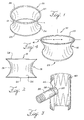
- the hyperboloid fixation coupling 10 may include nitinol rings 25 and 28 on its proximal and distal ends that are self-expanding.
- the coupling 10 may be integrated with a small-vessel stent graft for joining with a fenestrated stent graft.
- Figure 1 shows a fixation coupling 10 with two rings 25 and 28 that are placed on either side of the hyperboloid area 15.
- the rings 25 and 28 may include radiopaque elements to assist an operator in viewing the placement under fluoroscopy.
- the hyperboloid area 15 has an apex 13, or middle point, that is slightly larger in diameter than the diameter of the fenestration of a fenestrated graft 40 when not implanted.
- the smallest diameter of the hyperboloid can be at least the diameter of the fenestration 42, and preferably larger than the diameter of the fenestration 42.
- the fenestration 42 may be provided with a support ring surrounding the perimeter of the fenestration 42.
- the support ring may be made of a material that permits visualisation of the support ring during deployment of the hyperboloid area 15 within the fenestration 42.
- the support ring also may be of a material that expands to a larger diameter and then contracts to a smaller diameter to contact and seal against the hyperboloid area 15.
- the fixation coupling 10 has two outer extents 21, 26 that are the outermost points on the material.
- the first outer extent 21 and the second outer extent 26 are immediately adjacent the distal ring 28 and proximal ring 25, respectively.
- the outer extents (21, 26) have diameters that may be up to 20% larger in diameter than the apex 13.
- the diameters of both rings 28, 25 may be larger than any diameter in the hyperboloid area 15.
- the hyperboloid area 15 of the small vessel stent graft 30 allows for multi-directional movement without compromising the integrity of the sealing zone and, thus, reduces any stress on the small vessel stent graft 30.
- the hyperboloid area 15 may act also as a moveable joint resembling an open-ended ball joint.
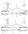
- Figure 4 shows a fixation coupling 10 with a distal ring 23 that is elliptical.
- the bottom, or proximal, ring 25 is circular. Both rings in some fixation couplings 10 described herein may also be elliptical rings.
- the elliptical distal ring 23 has a directrix 4 that may be greater than any diameter in the hyperboloid area 15.
- the directrix 4 may also be greater than the fenestration diameter in the stent graft to which it may be attached.
- the system may include a first prosthesis for implantation in the primary vessel with the first prosthesis having a tubular wall, a lumen therethrough, and a fenestration in the tubular wall.
- the system may include also a second prosthesis for implantation in the secondary vessel. This second prosthesis may include a fixation coupling as described herein, where the diameter of at least one of the rings is larger than any diameter of the hyperboloid area.
- the deployment methods although not part of the present invention provide accurate placement of the small vessel stent graft with fenestrated stent grafts. Tactile feedback is provided to the operator when one of the rings abuts the wall around the fenestration. A fully deployed ring will not go through the fenestration and, as such, the operator will feel such resistance. This will help prevent misplacing the coupling and the small vessel stent graft. This lets the surgeon know that the small vessel stent graft is properly placed before complete deployment.
- the method may include deploying the first prosthesis 60 in a primary vessel and aligning the fenestration with a secondary vessel.
- the fixation coupling 10 may be deployed in the fenestration by placing the proximal ring 25 in the lumen of the first prosthesis 60 and abutting the proximal ring 25 against an internal side of the wall 67 surrounding the fenestration 65.
- the distal ring 28 may be placed outside the lumen of the first prosthesis 60 and deployed such that the fenestration 65 surrounds the hyperboloid area 15 to form a joint.
- the first prosthesis is a fenestrated graft 60 that has been implanted into a primary vessel, such as an aorta, having an aneurysm 110.
- the fenestration 65 is aligned with the opening of the branch vessel, such as the renal artery 100. Radiopaque markers may be used in placing the fenestrated graft 60 in the artery.
- a guidewire 64 is threaded through the fenestrated graft 60, through the fenestration 65, and into the renal artery.
- a balloon-expandable or self-expanding small vessel stent graft 62 with a fixation coupling is inserted over the guidewire 64 in Figure 5B using a delivery system 66.
- the delivery system 66 is advanced through the fenestration 65 and into the renal artery 100.
- the delivery system 66 has been advanced until the proximal ring 25 of the fixation coupling 10 is proximal to the internal side of the wall 67 surrounding the fenestration 65 and the distal ring 28 is on the distal side of the fenestration 65.
- the hyperboloid section 15 is surrounded by the fenestration 65.
- the proximal ring 25 has been deployed while the distal ring 28 is only partially deployed. When the proximal ring 25 is pushed in a distal direction to abut the wall 67 surrounding the fenestration 65, the distal second ring 28 may be deployed fully as shown in Figure 5E.
- Figure 5F shows the system of endoprostheses with a fixation coupling 10 when implantation is complete.
- the method also may include a step where the small vessel stent graft 62 is advanced into a branch vessel such as the renal artery 100 until the distal ring 28 is just distal to the fenestration 65 and deployed.
- the small vessel stent graft 62 may be pulled in a proximal direction such that the deployed distal ring 28 abuts the external side of the wall surrounding the fenestration 65.
- the proximal ring 25 may then be deployed to surround the fenestration 65 with the fixation coupling 10.
- the proximal ring 25 can be deployed while advancing the small vessel stent graft 62 through the fenestrated graft 60. Once the proximal ring 25 abuts the wall 67 surrounding the fenestration 65, the operator can feel the obstruction.
- the deployed proximal ring 25 provides tactile feedback when abutting the wall 67.
- a branch vessel stent graft may include a distal end and a body portion configured for placement in a body vessel branching from a main body vessel. There may be a proximal end configured for at least partial placement within an internal branch of a branched stent graft.
- the small vessel stent graft 62 also may have a fixation coupling 50 positioned at or near the proximal end, where the fixation coupling 50 includes a flared proximal opening 57 with a diameter larger than any diameter of the small vessel stent graft 62, and a ring 55 surrounding the flared proximal opening 57.
- FIG. 6 shows a bell-bottomed shape fixation coupling 50.
- This fixation coupling 50 may be integrated with the proximal portion of the small vessel stent graft 62.
- a ring 55 is at the flared proximal opening 57 and may be stitched around the opening 57 or embedded in the graft material.
- the fixation coupling 50 may be self-expanding or balloon expandable.
- the ring 55 may include radiopaque elements and may have an elliptical shape. If the ring 55 is an ellipse, the flared proximal opening 57 may be an ellipse also.
- the directrix of an elliptical ring and the flared proximal elliptical opening may be larger than any diameter in the bell-bottomed fixation coupling 50.
- the bell-bottomed shaped fixation coupling 50 may be implanted in the internal branches 92, 94, 96 of an arch branch device 90 as shown in Figure 7 .
- the internal branches 92, 94, 96 correspond, respectively, to the innominate, left common carotid, and the left subclavian arteries when the device 90 is planted in the aortic arch.
- Figures 8A to 8D show steps that may be used in deploying a small vessel stent graft 62 with a bell-bottomed fixation coupling 50 into internal branch 94.
- a guidewire 72 is inserted through a small incision made in the patient's neck to access the left common carotid artery.
- the guidewire 72 is advanced through the artery and then into the internal branch 94 in a proximal direction toward the heart as shown in Figure 8A .
- a delivery sheath 76 follows over the guidewire 72.
- the delivery sheath 76 is pulled back in Figure 8C to begin deployment of the small vessel stent graft 62 by revealing the fixation coupling 50.
- the fixation coupling 50 may be self-expanding or balloon expandable.
- the diameters of the fixation coupling 50 and the ring 55 are greater than the diameter of the internal branch 94, thus preventing the small vessel stent graft 62 from withdrawing from the internal branch 94 in a distal direction away from the internal branch opening 79.
- Figure 8D shows the fixation coupling 50 fully deployed.
Description
- The present invention relates to a branch vessel stent graft endoluminal prostheses with a fixation coupling. In particular, it relates to a fixation joint for use with a fenestrated stent graft and a smaller branch stent that provides secure and complete rotational movement.
- Using stent grafts to treat aneurysms is common in the medical field. Stent grafts are deployed by accessing vasculature with a small incision in the skin and guiding a delivery system to the target area. This intraluminal delivery is less invasive and generally preferred over more intrusive forms of surgery. Multiple stent grafts may be implanted using intraluminal delivery to provide a system of interconnected stent grafts. Interconnected stent grafts can be made of fenestrated grafts and smaller side branch stents, including bifurcated grafts.
- Sometimes aneurysms engulf a vessel and its branch vessels, such as the aorta and the renal arteries or the aortic arch and the branch arteries. In such instances a fenestrated graft can be implanted in the main vessel while smaller branch grafts can be deployed in the branch arteries. The main vessel grafts have fenestrations that correspond with the opening of the branch vessel. The smaller branch grafts are joined with the main vessel graft at the fenestrations. Due to the torsion and rigors of the endovascular system, this juncture can be subject to significant stress.
-
US 2008/0167704 discloses a branch vessel stent graft and delivery system. -
US 2006/0155359 discloses a branch vessel graft design and deployment method. - According to an aspect of the present invention, there is provided a system for repairing an anatomical vessel at the junction of a main anatomical vessel and a branch anatomical vessel as specified in
claim 1. - Preferred embodiments of the present invention are described below, by way of example only, with reference to the accompanying drawings, in which:
-
FIG. 1 is a perspective view of a hyperboloid shaped fixation coupling; -
FIG. 2 is a side view of the hyperboloid shaped fixation coupling; -
FIG. 3 is a longitudinal cross-sectional view of a fenestrated stent graft coupled to a hyperboloid shaped fixation coupling on the proximal end of a small vessel stent graft; -
FIG. 4 is a perspective view of a hyperboloid shaped fixation coupling with an elliptical ring on one end; -
FIGS. 5A to 5F are cross sectional schematic diagrams showing the steps of deploying a stent graft having a hyperboloid shaped coupling into a renal artery and mating with a fenestrated stent graft implanted in the aorta; -
FIG. 6 is a perspective view of a bell shaped fixation coupling in an internal branch; -
FIG. 7 is an internally branched stent graft for implantation in the aortic arch; and -
FIGS. 8A to 8D are cross-sectional views of the deployment steps of a secondary graft with a bell-shaped fixation coupling with a fenestrated stentFigures 6 to 8 do not show embodiments of the present invention. - The term "prosthesis" means any replacement for a body part or for a function of that body part or any device that enhances or adds functionality to a physiological system.
- The term "graft or graft material" means a generally cannular or tubular member which acts as an artificial vessel or prosthesis. A graft by itself or with the addition of other elements, such as structural components, may be an endoluminal prosthesis. The graft may comprise a single material, a blend of materials, a weave, a laminate, or a composite of two or more materials.
- The graft material is a biocompatible material that is both flexible and abrasion resistant. Furthermore, the graft material should be selected from those materials that are particularly well suited for thermoplastic deformation, such that the material may be thermoplastically fused to a stent. The woven graft material can be a woven polyester. The woven graft material may be a polyethylene terephthalate (PET), such as DACRON® (DUPONT, Wilmington, DE) or TWILLWEAVE MICREL® (VASCUTEK, Renfrewshire, Scotland). Woven polyesters, such as Dacron, possess varying degrees of porosity, where the degree of porosity may be selectively controlled based on the weaving or knitting process that is used to produce the woven polyester. Consequently, depending on the application, the porosity may be adjusted to encourage incorporation of a patient's tissue into the woven graft material, which in turn may more securely anchor the prosthesis within the patient's vessel or lumen. Furthermore, the degree of porosity may be adjusted also to provide a woven graft material that is impermeable to liquids, including blood or other physiological fluids.
- Throughout this specification, when discussing the application of this invention to the aorta or other blood vessels, the term "distal," with respect to a prosthesis, is intended to refer to a location that is, or a portion of the prosthesis that when implanted is, further downstream with respect to blood flow. The term "distally" means in the direction of blood flow or further downstream. The term "proximal" is intended to refer to a location that is, or a portion of the prosthesis that when implanted is, further upstream with respect to blood flow. The term "proximally" means in the direction opposite to the direction of blood flow, or further upstream.
- A branch vessel stent graft includes a proximal end, a distal end, and a body portion configured for placement in a body vessel branching from a main body vessel. For instance, the branch vessel stent graft may be placed in a renal artery, which branches from the aorta, or in the innominate artery, which branches from the aortic arch. The stent graft also includes a fixation coupling positioned at or near the proximal end and configured for placement within a fenestration of a fenestrated device. The fenestrated device may be a fenestrated stent graft that may be placed in a main blood vessel. The fixation coupling includes a distal ring, a proximal ring, and a hyperboloid area positioned between the rings. The rings are non-helical.
- The fixation coupling also may have first and second outer extents that are hyperboloid areas closest to the proximal and distal rings. The diameter of at least one of the rings is greater than any diameter of the hyperboloid area.
- The
hyperboloid fixation coupling 10 may includenitinol rings coupling 10 may be integrated with a small-vessel stent graft for joining with a fenestrated stent graft.Figure 1 shows afixation coupling 10 with tworings hyperboloid area 15. Therings hyperboloid area 15 has anapex 13, or middle point, that is slightly larger in diameter than the diameter of the fenestration of afenestrated graft 40 when not implanted. As shown inFigure 3 , when thecoupling 10 is implanted, theapex 13 is squeezed to fit within thefenestration 42 and to provide a secure seal. The smallest diameter of the hyperboloid can be at least the diameter of thefenestration 42, and preferably larger than the diameter of thefenestration 42. Thefenestration 42 may be provided with a support ring surrounding the perimeter of thefenestration 42. The support ring may be made of a material that permits visualisation of the support ring during deployment of thehyperboloid area 15 within thefenestration 42. The support ring also may be of a material that expands to a larger diameter and then contracts to a smaller diameter to contact and seal against thehyperboloid area 15. - The
fixation coupling 10 has twoouter extents outer extent 21 and the secondouter extent 26 are immediately adjacent thedistal ring 28 andproximal ring 25, respectively. The outer extents (21, 26) have diameters that may be up to 20% larger in diameter than the apex 13. There may becouplings 10 with outer extents greater than 20% of the apex 13 diameter. When deployed, thedistal ring 28 and theproximal ring 25 expand thehyperboloid area 15 about thefenestration 42. Deployment seals off thefenestration 42 and connects thesmall vessel device 30 to thefenestrated stent graft 40 as shown inFigure 3 . The diameters of bothrings hyperboloid area 15. Thehyperboloid area 15 of the smallvessel stent graft 30 allows for multi-directional movement without compromising the integrity of the sealing zone and, thus, reduces any stress on the smallvessel stent graft 30. Thehyperboloid area 15 may act also as a moveable joint resembling an open-ended ball joint. -
Figure 4 shows afixation coupling 10 with adistal ring 23 that is elliptical. The bottom, or proximal,ring 25 is circular. Both rings in somefixation couplings 10 described herein may also be elliptical rings. The ellipticaldistal ring 23 has a directrix 4 that may be greater than any diameter in thehyperboloid area 15. The directrix 4 may also be greater than the fenestration diameter in the stent graft to which it may be attached. There can also be fenestrated grafts that include an elliptical fenestration. - There is a method of deploying a system of endoluminal prostheses with a fixation coupling that provides angular and rotational movement in a body having a primary vessel in communication with a secondary vessel. The system may include a first prosthesis for implantation in the primary vessel with the first prosthesis having a tubular wall, a lumen therethrough, and a fenestration in the tubular wall. The system may include also a second prosthesis for implantation in the secondary vessel. This second prosthesis may include a fixation coupling as described herein, where the diameter of at least one of the rings is larger than any diameter of the hyperboloid area.
- The deployment methods although not part of the present invention provide accurate placement of the small vessel stent graft with fenestrated stent grafts. Tactile feedback is provided to the operator when one of the rings abuts the wall around the fenestration. A fully deployed ring will not go through the fenestration and, as such, the operator will feel such resistance. This will help prevent misplacing the coupling and the small vessel stent graft. This lets the surgeon know that the small vessel stent graft is properly placed before complete deployment.
- The method may include deploying the
first prosthesis 60 in a primary vessel and aligning the fenestration with a secondary vessel. Thefixation coupling 10 may be deployed in the fenestration by placing theproximal ring 25 in the lumen of thefirst prosthesis 60 and abutting theproximal ring 25 against an internal side of thewall 67 surrounding thefenestration 65. Thedistal ring 28 may be placed outside the lumen of thefirst prosthesis 60 and deployed such that thefenestration 65 surrounds thehyperboloid area 15 to form a joint. - As shown in
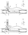
Figure 5A , the first prosthesis is afenestrated graft 60 that has been implanted into a primary vessel, such as an aorta, having ananeurysm 110. Thefenestration 65 is aligned with the opening of the branch vessel, such as therenal artery 100. Radiopaque markers may be used in placing thefenestrated graft 60 in the artery. Aguidewire 64 is threaded through thefenestrated graft 60, through thefenestration 65, and into the renal artery. A balloon-expandable or self-expanding smallvessel stent graft 62 with a fixation coupling is inserted over theguidewire 64 inFigure 5B using adelivery system 66. Thedelivery system 66 is advanced through thefenestration 65 and into therenal artery 100. - In
Figure 5C , thedelivery system 66 has been advanced until theproximal ring 25 of thefixation coupling 10 is proximal to the internal side of thewall 67 surrounding thefenestration 65 and thedistal ring 28 is on the distal side of thefenestration 65. Thehyperboloid section 15 is surrounded by thefenestration 65. InFigure 5D , theproximal ring 25 has been deployed while thedistal ring 28 is only partially deployed. When theproximal ring 25 is pushed in a distal direction to abut thewall 67 surrounding thefenestration 65, the distalsecond ring 28 may be deployed fully as shown inFigure 5E. Figure 5F shows the system of endoprostheses with afixation coupling 10 when implantation is complete. - The method also may include a step where the small
vessel stent graft 62 is advanced into a branch vessel such as therenal artery 100 until thedistal ring 28 is just distal to thefenestration 65 and deployed. The smallvessel stent graft 62 may be pulled in a proximal direction such that the deployeddistal ring 28 abuts the external side of the wall surrounding thefenestration 65. Theproximal ring 25 may then be deployed to surround thefenestration 65 with thefixation coupling 10. In another method, theproximal ring 25 can be deployed while advancing the smallvessel stent graft 62 through thefenestrated graft 60. Once theproximal ring 25 abuts thewall 67 surrounding thefenestration 65, the operator can feel the obstruction. The deployedproximal ring 25 provides tactile feedback when abutting thewall 67. - A branch vessel stent graft may include a distal end and a body portion configured for placement in a body vessel branching from a main body vessel. There may be a proximal end configured for at least partial placement within an internal branch of a branched stent graft. The small
vessel stent graft 62 also may have afixation coupling 50 positioned at or near the proximal end, where thefixation coupling 50 includes a flaredproximal opening 57 with a diameter larger than any diameter of the smallvessel stent graft 62, and aring 55 surrounding the flaredproximal opening 57. -
Figure 6 shows a bell-bottomedshape fixation coupling 50. Thisfixation coupling 50 may be integrated with the proximal portion of the smallvessel stent graft 62. Aring 55 is at the flaredproximal opening 57 and may be stitched around theopening 57 or embedded in the graft material. Thefixation coupling 50 may be self-expanding or balloon expandable. Thering 55 may include radiopaque elements and may have an elliptical shape. If thering 55 is an ellipse, the flaredproximal opening 57 may be an ellipse also. The directrix of an elliptical ring and the flared proximal elliptical opening may be larger than any diameter in the bell-bottomedfixation coupling 50. - The bell-bottomed
shaped fixation coupling 50 may be implanted in theinternal branches arch branch device 90 as shown inFigure 7 . Theinternal branches device 90 is planted in the aortic arch.Figures 8A to 8D show steps that may be used in deploying a smallvessel stent graft 62 with a bell-bottomedfixation coupling 50 intointernal branch 94. Aguidewire 72 is inserted through a small incision made in the patient's neck to access the left common carotid artery. Theguidewire 72 is advanced through the artery and then into theinternal branch 94 in a proximal direction toward the heart as shown inFigure 8A . InFigure 8B , adelivery sheath 76 follows over theguidewire 72. Thedelivery sheath 76 is pulled back inFigure 8C to begin deployment of the smallvessel stent graft 62 by revealing thefixation coupling 50. Thefixation coupling 50 may be self-expanding or balloon expandable. The diameters of thefixation coupling 50 and thering 55 are greater than the diameter of theinternal branch 94, thus preventing the smallvessel stent graft 62 from withdrawing from theinternal branch 94 in a distal direction away from theinternal branch opening 79.Figure 8D shows thefixation coupling 50 fully deployed.
Claims (12)
- A system for repairing an anatomical vessel at the junction of a main anatomical vessel and branch anatomical vessel including:a primary stent graft (40; 60) configured for placement in the main anatomical vessel, including a tubular graft material, at least one stent, a fenestration (42; 65) in a sidewall of the tubular graft material, the fenestration having a diameter;a branch vessel stent graft (30; 62) including:a proximal end;a distal end;a body portion configured for placement in a body vessel branching from a main body vessel; anda fixation coupling (10) positioned at or near the proximal end and configured for placement within the fenestration;wherein the fixation coupling comprises a distal non-helical ring (28) coupled to its distal end, a proximal non-helical ring (25) coupled to its proximal end, characterized by a hyperboloid-shaped section (15) positioned between the rings, and a first outer extent (21) and a second outer extent (26), wherein the diameter or directrix (4) of both of the rings is larger than any diameter of the hyperboloid-shaped section; andwherein the diameter of the apex (13) of the hyperboloid-shaped section is larger than the diameter of the fenestration.
- A system as claimed in claim 1, wherein the distal ring (28) is an ellipse.
- A system as claimed in claim 1 or 2, wherein the proximal ring (25) is an ellipse.
- A system as claimed in claim 1, 2 or 3, wherein the distal ring (28) includes a radiopaque element.
- A system as claimed in any preceding claim, wherein the proximal ring (25) includes a radiopaque element.
- A system as claimed in any preceding claim, wherein the fixation coupling (10; 50) is deployable by balloon expansion.
- A system as claimed in any of claims 1 to 5, wherein the fixation coupling (10; 50) is self-expanding.
- A system as claimed in any preceding claim, wherein the fixation coupling (10) is integrated with the branch vessel stent graft (30; 62).
- A system as claimed in any preceding claim, wherein the fenestration (42) is provided with a support ring surrounding the perimeter of the fenestration.
- A system as claimed in claim 9, wherein the support ring is of a material that permits visualisation of the support ring during deployment of the hyperboloid-shaped section (15) within the fenestration (42).
- A system as claimed in claim 9 or 10, wherein the support ring is of a material that expands and then contracts to contact and seal against the hyperboloid-shaped section (15).
- A system as claimed in any preceding claim, wherein the fixation coupling (10) has a first outer extent (21) immediately adjacent the distal ring (28) and a second outer extent immediately adjacent the proximal ring (25), and wherein the outer extents (21, 26) have diameters up to 20% larger than the diameter of the apex (13) of the hyperboloid-shaped section.
Applications Claiming Priority (2)
| Application Number | Priority Date | Filing Date | Title |
|---|---|---|---|
| US9215008P | 2008-08-27 | 2008-08-27 | |
| PCT/US2009/004805 WO2010024867A1 (en) | 2008-08-27 | 2009-08-24 | Stent graft fixation coupling |
Publications (2)
| Publication Number | Publication Date |
|---|---|
| EP2349084A1 EP2349084A1 (en) | 2011-08-03 |
| EP2349084B1 true EP2349084B1 (en) | 2016-10-26 |
Family
ID=41112816
Family Applications (1)
| Application Number | Title | Priority Date | Filing Date |
|---|---|---|---|
| EP09789194.9A Active EP2349084B1 (en) | 2008-08-27 | 2009-08-24 | Stent graft fixation coupling |
Country Status (5)
| Country | Link |
|---|---|
| US (1) | US8915955B2 (en) |
| EP (1) | EP2349084B1 (en) |
| JP (1) | JP5531016B2 (en) |
| AU (1) | AU2009286139B2 (en) |
| WO (1) | WO2010024867A1 (en) |
Families Citing this family (40)
| Publication number | Priority date | Publication date | Assignee | Title |
|---|---|---|---|---|
| US7147661B2 (en) | 2001-12-20 | 2006-12-12 | Boston Scientific Santa Rosa Corp. | Radially expandable stent |
| US8540764B2 (en) * | 2009-04-17 | 2013-09-24 | Medtronic Vascular, Inc. | Mobile external coupling for branch vessel connection |
| US8506622B2 (en) * | 2009-04-17 | 2013-08-13 | Medtronic Vascular, Inc. | Mobile external coupling for branch vessel connection |
| WO2011064782A2 (en) | 2009-11-30 | 2011-06-03 | Endospan Ltd. | Multi-component stent-graft system for implantation in a blood vessel with multiple branches |
| WO2011070576A1 (en) | 2009-12-08 | 2011-06-16 | Endospan Ltd. | Endovascular stent-graft system with fenestrated and crossing stent-grafts |
| AU2010201067B1 (en) * | 2010-03-19 | 2011-06-09 | Cook Incorporated | Thoracic stent graft |
| AU2010202544B1 (en) * | 2010-06-18 | 2010-08-26 | Cook Incorporated | Side branch stent graft |
| US9566149B2 (en) | 2010-11-16 | 2017-02-14 | W. L. Gore & Associates, Inc. | Devices and methods for in situ fenestration of a stent-graft at the site of a branch vessel |
| US20120136431A1 (en) * | 2010-11-29 | 2012-05-31 | Wei-Hui Chen | Stent Graft System |
| US9254209B2 (en) | 2011-07-07 | 2016-02-09 | Endospan Ltd. | Stent fixation with reduced plastic deformation |
| US9839510B2 (en) | 2011-08-28 | 2017-12-12 | Endospan Ltd. | Stent-grafts with post-deployment variable radial displacement |
| CN106333765B (en) | 2011-11-11 | 2019-10-11 | 波顿医疗公司 | General endovascular graft object |
| BR112014011779A2 (en) | 2011-11-16 | 2017-05-09 | Bolton Medical Inc | device and method for the repair of branched aortic vessel |
| CN102499791A (en) * | 2011-11-18 | 2012-06-20 | 姬尚义 | Artery connecting lantern ring and artery connector |
| WO2013084235A2 (en) | 2011-12-04 | 2013-06-13 | Endospan Ltd. | Branched stent-graft system |
| FR2984112B1 (en) * | 2011-12-15 | 2013-12-06 | Assist Publ Hopitaux De Paris | ENDOVASCULAR PROSTHESIS |
| US9811613B2 (en) | 2012-05-01 | 2017-11-07 | University Of Washington Through Its Center For Commercialization | Fenestration template for endovascular repair of aortic aneurysms |
| FR2995206B1 (en) * | 2012-09-11 | 2014-09-26 | Univ Strasbourg | TREATMENT KIT, TREATMENT DEVICE AND METHOD FOR MANUFACTURING THE SAME |
| CN105208969B (en) | 2013-03-11 | 2017-10-20 | 恩多斯潘有限公司 | Multicompartment stent graft system for dissection of aorta |
| US9402751B2 (en) | 2013-03-13 | 2016-08-02 | W. L. Gore & Associates, Inc. | Devices and methods for treatment of the aortic arch |
| WO2015075708A1 (en) | 2013-11-19 | 2015-05-28 | Endospan Ltd. | Stent system with radial-expansion locking |
| US9808363B2 (en) * | 2014-09-10 | 2017-11-07 | The Cleveland Clinic Foundation | Frame structures, stent grafts incorporating the same, and methods for extended aortic repair |
| ES2731434T3 (en) | 2014-09-23 | 2019-11-15 | Bolton Medical Inc | Vascular repair devices |
| US10485684B2 (en) | 2014-12-18 | 2019-11-26 | Endospan Ltd. | Endovascular stent-graft with fatigue-resistant lateral tube |
| WO2017176730A1 (en) | 2016-04-05 | 2017-10-12 | Bolton Medical, Inc. | Stent graft with internal tunnels and fenestrations and methods of use |
| US20170340462A1 (en) | 2016-05-25 | 2017-11-30 | Bolton Medical, Inc. | Stent grafts and methods of use for treating aneurysms |
| EP3468505B1 (en) | 2016-06-13 | 2021-02-24 | Aortica Corporation | Systems and devices for marking and/or reinforcing fenestrations in prosthetic implants |
| AU2017306141A1 (en) | 2016-08-02 | 2019-03-07 | Aortica Corporation | Systems, devices, and methods for coupling a prosthetic implant to a fenestrated body |
| WO2018156849A1 (en) | 2017-02-24 | 2018-08-30 | Bolton Medical, Inc. | Vascular prosthesis with fenestration ring and methods of use |
| EP3585306B1 (en) | 2017-02-24 | 2021-01-27 | Bolton Medical, Inc. | System to radially constrict a stent graft |
| WO2018156848A1 (en) * | 2017-02-24 | 2018-08-30 | Bolton Medical, Inc. | Vascular prosthesis with crimped adapter and methods of use |
| WO2018156850A1 (en) | 2017-02-24 | 2018-08-30 | Bolton Medical, Inc. | Stent graft with fenestration lock |
| WO2018156851A1 (en) | 2017-02-24 | 2018-08-30 | Bolton Medical, Inc. | Vascular prosthesis with moveable fenestration |
| WO2018156847A1 (en) | 2017-02-24 | 2018-08-30 | Bolton Medical, Inc. | Delivery system and method to radially constrict a stent graft |
| US10660770B2 (en) | 2017-07-18 | 2020-05-26 | Cook Medical Technologies Llc | Method of making an internal bidirectional branch |
| JP7271510B2 (en) * | 2017-09-25 | 2023-05-11 | ボルトン メディカル インコーポレイテッド | Systems, devices and methods for coupling prosthetic implants to fenestrated bodies |
| EP4049633A1 (en) | 2017-10-31 | 2022-08-31 | Bolton Medical, Inc. | Distal torque component, delivery system and method of using same |
| CN109646160A (en) * | 2019-01-29 | 2019-04-19 | 戴向晨 | Branched membrane-covered support in a kind of novel aorta |
| CA3133857A1 (en) | 2019-03-20 | 2020-09-24 | inQB8 Medical Technologies, LLC | Aortic dissection implant |
| US20200405515A1 (en) * | 2019-06-25 | 2020-12-31 | Atrium Medical Corporation | Stent device including a flarable crown |
Citations (1)
| Publication number | Priority date | Publication date | Assignee | Title |
|---|---|---|---|---|
| US20060155359A1 (en) * | 2005-01-13 | 2006-07-13 | Medtronic Vascular, Inc. | Branch vessel graft design and deployment method |
Family Cites Families (7)
| Publication number | Priority date | Publication date | Assignee | Title |
|---|---|---|---|---|
| US5904697A (en) * | 1995-02-24 | 1999-05-18 | Heartport, Inc. | Devices and methods for performing a vascular anastomosis |
| US5695504A (en) * | 1995-02-24 | 1997-12-09 | Heartport, Inc. | Devices and methods for performing a vascular anastomosis |
| CN1218414A (en) * | 1996-02-02 | 1999-06-02 | 血管转换公司 | Methods and apparatus for blocking flow through blood vessels |
| US6994713B2 (en) * | 1998-01-30 | 2006-02-07 | St. Jude Medical Atg, Inc. | Medical graft connector or plug structures, and methods of making and installing same |
| NL1010386C2 (en) * | 1998-10-23 | 2000-04-26 | Eric Berreklouw | Anastomosis device. |
| US6890349B2 (en) * | 2000-10-13 | 2005-05-10 | Rex Medical, L.P. | Covered stent with side branch |
| US8216298B2 (en) * | 2007-01-05 | 2012-07-10 | Medtronic Vascular, Inc. | Branch vessel graft method and delivery system |
-
2009
- 2009-08-24 AU AU2009286139A patent/AU2009286139B2/en active Active
- 2009-08-24 WO PCT/US2009/004805 patent/WO2010024867A1/en active Application Filing
- 2009-08-24 EP EP09789194.9A patent/EP2349084B1/en active Active
- 2009-08-24 US US12/546,232 patent/US8915955B2/en active Active
- 2009-08-24 JP JP2011524979A patent/JP5531016B2/en active Active
Patent Citations (1)
| Publication number | Priority date | Publication date | Assignee | Title |
|---|---|---|---|---|
| US20060155359A1 (en) * | 2005-01-13 | 2006-07-13 | Medtronic Vascular, Inc. | Branch vessel graft design and deployment method |
Also Published As
| Publication number | Publication date |
|---|---|
| US8915955B2 (en) | 2014-12-23 |
| AU2009286139A1 (en) | 2010-03-04 |
| JP2012501205A (en) | 2012-01-19 |
| WO2010024867A1 (en) | 2010-03-04 |
| JP5531016B2 (en) | 2014-06-25 |
| US20100057186A1 (en) | 2010-03-04 |
| AU2009286139B2 (en) | 2013-04-04 |
| EP2349084A1 (en) | 2011-08-03 |
Similar Documents
| Publication | Publication Date | Title |
|---|---|---|
| EP2349084B1 (en) | Stent graft fixation coupling | |
| EP1517651B1 (en) | Thoracic aortic aneurysm stent graft | |
| US8216298B2 (en) | Branch vessel graft method and delivery system | |
| JP4464972B2 (en) | Interconnected leg extensions for endoluminal prostheses | |
| US7674284B2 (en) | Endoluminal graft | |
| EP1737389B1 (en) | Stent graft repair device | |
| EP1441782B1 (en) | Interlocking endoluminal stent-graft | |
| EP1684668B1 (en) | Aorta and branch vessel stent grafts and system | |
| JP4291971B2 (en) | Modified guidewire access modulator endoluminal prosthesis with connections | |
| EP3005980B1 (en) | Branch vessel prothesis | |
| US20090222078A1 (en) | Prosthesis for Implantation in Aorta and Method of Using Same | |
| EP3040050B1 (en) | Support structures for prostheses with branching portions | |
| EP2702960B1 (en) | Endoluminal prosthesis and delivery device |
Legal Events
| Date | Code | Title | Description |
|---|---|---|---|
| PUAI | Public reference made under article 153(3) epc to a published international application that has entered the european phase |
Free format text: ORIGINAL CODE: 0009012 |
|
| 17P | Request for examination filed |
Effective date: 20110325 |
|
| AK | Designated contracting states |
Kind code of ref document: A1 Designated state(s): AT BE BG CH CY CZ DE DK EE ES FI FR GB GR HR HU IE IS IT LI LT LU LV MC MK MT NL NO PL PT RO SE SI SK SM TR |
|
| DAX | Request for extension of the european patent (deleted) | ||
| 17Q | First examination report despatched |
Effective date: 20131021 |
|
| GRAP | Despatch of communication of intention to grant a patent |
Free format text: ORIGINAL CODE: EPIDOSNIGR1 |
|
| INTG | Intention to grant announced |
Effective date: 20160603 |
|
| GRAJ | Information related to disapproval of communication of intention to grant by the applicant or resumption of examination proceedings by the epo deleted |
Free format text: ORIGINAL CODE: EPIDOSDIGR1 |
|
| GRAR | Information related to intention to grant a patent recorded |
Free format text: ORIGINAL CODE: EPIDOSNIGR71 |
|
| GRAS | Grant fee paid |
Free format text: ORIGINAL CODE: EPIDOSNIGR3 |
|
| GRAA | (expected) grant |
Free format text: ORIGINAL CODE: 0009210 |
|
| INTC | Intention to grant announced (deleted) | ||
| AK | Designated contracting states |
Kind code of ref document: B1 Designated state(s): AT BE BG CH CY CZ DE DK EE ES FI FR GB GR HR HU IE IS IT LI LT LU LV MC MK MT NL NO PL PT RO SE SI SK SM TR |
|
| INTG | Intention to grant announced |
Effective date: 20160919 |
|
| REG | Reference to a national code |
Ref country code: GB Ref legal event code: FG4D |
|
| REG | Reference to a national code |
Ref country code: CH Ref legal event code: EP |
|
| REG | Reference to a national code |
Ref country code: AT Ref legal event code: REF Ref document number: 839446 Country of ref document: AT Kind code of ref document: T Effective date: 20161115 |
|
| REG | Reference to a national code |
Ref country code: IE Ref legal event code: FG4D |
|
| REG | Reference to a national code |
Ref country code: DE Ref legal event code: R096 Ref document number: 602009041977 Country of ref document: DE |
|
| REG | Reference to a national code |
Ref country code: LT Ref legal event code: MG4D |
|
| PG25 | Lapsed in a contracting state [announced via postgrant information from national office to epo] |
Ref country code: LV Free format text: LAPSE BECAUSE OF FAILURE TO SUBMIT A TRANSLATION OF THE DESCRIPTION OR TO PAY THE FEE WITHIN THE PRESCRIBED TIME-LIMIT Effective date: 20161026 |
|
| REG | Reference to a national code |
Ref country code: NL Ref legal event code: MP Effective date: 20161026 |
|
| REG | Reference to a national code |
Ref country code: AT Ref legal event code: MK05 Ref document number: 839446 Country of ref document: AT Kind code of ref document: T Effective date: 20161026 |
|
| PG25 | Lapsed in a contracting state [announced via postgrant information from national office to epo] |
Ref country code: SE Free format text: LAPSE BECAUSE OF FAILURE TO SUBMIT A TRANSLATION OF THE DESCRIPTION OR TO PAY THE FEE WITHIN THE PRESCRIBED TIME-LIMIT Effective date: 20161026 Ref country code: GR Free format text: LAPSE BECAUSE OF FAILURE TO SUBMIT A TRANSLATION OF THE DESCRIPTION OR TO PAY THE FEE WITHIN THE PRESCRIBED TIME-LIMIT Effective date: 20170127 Ref country code: LT Free format text: LAPSE BECAUSE OF FAILURE TO SUBMIT A TRANSLATION OF THE DESCRIPTION OR TO PAY THE FEE WITHIN THE PRESCRIBED TIME-LIMIT Effective date: 20161026 Ref country code: NO Free format text: LAPSE BECAUSE OF FAILURE TO SUBMIT A TRANSLATION OF THE DESCRIPTION OR TO PAY THE FEE WITHIN THE PRESCRIBED TIME-LIMIT Effective date: 20170126 |
|
| PG25 | Lapsed in a contracting state [announced via postgrant information from national office to epo] |
Ref country code: IS Free format text: LAPSE BECAUSE OF FAILURE TO SUBMIT A TRANSLATION OF THE DESCRIPTION OR TO PAY THE FEE WITHIN THE PRESCRIBED TIME-LIMIT Effective date: 20170226 Ref country code: AT Free format text: LAPSE BECAUSE OF FAILURE TO SUBMIT A TRANSLATION OF THE DESCRIPTION OR TO PAY THE FEE WITHIN THE PRESCRIBED TIME-LIMIT Effective date: 20161026 Ref country code: ES Free format text: LAPSE BECAUSE OF FAILURE TO SUBMIT A TRANSLATION OF THE DESCRIPTION OR TO PAY THE FEE WITHIN THE PRESCRIBED TIME-LIMIT Effective date: 20161026 Ref country code: NL Free format text: LAPSE BECAUSE OF FAILURE TO SUBMIT A TRANSLATION OF THE DESCRIPTION OR TO PAY THE FEE WITHIN THE PRESCRIBED TIME-LIMIT Effective date: 20161026 Ref country code: FI Free format text: LAPSE BECAUSE OF FAILURE TO SUBMIT A TRANSLATION OF THE DESCRIPTION OR TO PAY THE FEE WITHIN THE PRESCRIBED TIME-LIMIT Effective date: 20161026 Ref country code: PT Free format text: LAPSE BECAUSE OF FAILURE TO SUBMIT A TRANSLATION OF THE DESCRIPTION OR TO PAY THE FEE WITHIN THE PRESCRIBED TIME-LIMIT Effective date: 20170227 Ref country code: HR Free format text: LAPSE BECAUSE OF FAILURE TO SUBMIT A TRANSLATION OF THE DESCRIPTION OR TO PAY THE FEE WITHIN THE PRESCRIBED TIME-LIMIT Effective date: 20161026 Ref country code: BE Free format text: LAPSE BECAUSE OF FAILURE TO SUBMIT A TRANSLATION OF THE DESCRIPTION OR TO PAY THE FEE WITHIN THE PRESCRIBED TIME-LIMIT Effective date: 20161026 Ref country code: PL Free format text: LAPSE BECAUSE OF FAILURE TO SUBMIT A TRANSLATION OF THE DESCRIPTION OR TO PAY THE FEE WITHIN THE PRESCRIBED TIME-LIMIT Effective date: 20161026 |
|
| REG | Reference to a national code |
Ref country code: DE Ref legal event code: R097 Ref document number: 602009041977 Country of ref document: DE |
|
| PG25 | Lapsed in a contracting state [announced via postgrant information from national office to epo] |
Ref country code: DK Free format text: LAPSE BECAUSE OF FAILURE TO SUBMIT A TRANSLATION OF THE DESCRIPTION OR TO PAY THE FEE WITHIN THE PRESCRIBED TIME-LIMIT Effective date: 20161026 Ref country code: SK Free format text: LAPSE BECAUSE OF FAILURE TO SUBMIT A TRANSLATION OF THE DESCRIPTION OR TO PAY THE FEE WITHIN THE PRESCRIBED TIME-LIMIT Effective date: 20161026 Ref country code: RO Free format text: LAPSE BECAUSE OF FAILURE TO SUBMIT A TRANSLATION OF THE DESCRIPTION OR TO PAY THE FEE WITHIN THE PRESCRIBED TIME-LIMIT Effective date: 20161026 Ref country code: EE Free format text: LAPSE BECAUSE OF FAILURE TO SUBMIT A TRANSLATION OF THE DESCRIPTION OR TO PAY THE FEE WITHIN THE PRESCRIBED TIME-LIMIT Effective date: 20161026 Ref country code: CZ Free format text: LAPSE BECAUSE OF FAILURE TO SUBMIT A TRANSLATION OF THE DESCRIPTION OR TO PAY THE FEE WITHIN THE PRESCRIBED TIME-LIMIT Effective date: 20161026 |
|
| PG25 | Lapsed in a contracting state [announced via postgrant information from national office to epo] |
Ref country code: BG Free format text: LAPSE BECAUSE OF FAILURE TO SUBMIT A TRANSLATION OF THE DESCRIPTION OR TO PAY THE FEE WITHIN THE PRESCRIBED TIME-LIMIT Effective date: 20170126 Ref country code: SM Free format text: LAPSE BECAUSE OF FAILURE TO SUBMIT A TRANSLATION OF THE DESCRIPTION OR TO PAY THE FEE WITHIN THE PRESCRIBED TIME-LIMIT Effective date: 20161026 Ref country code: IT Free format text: LAPSE BECAUSE OF FAILURE TO SUBMIT A TRANSLATION OF THE DESCRIPTION OR TO PAY THE FEE WITHIN THE PRESCRIBED TIME-LIMIT Effective date: 20161026 |
|
| PLBE | No opposition filed within time limit |
Free format text: ORIGINAL CODE: 0009261 |
|
| STAA | Information on the status of an ep patent application or granted ep patent |
Free format text: STATUS: NO OPPOSITION FILED WITHIN TIME LIMIT |
|
| 26N | No opposition filed |
Effective date: 20170727 |
|
| PG25 | Lapsed in a contracting state [announced via postgrant information from national office to epo] |
Ref country code: SI Free format text: LAPSE BECAUSE OF FAILURE TO SUBMIT A TRANSLATION OF THE DESCRIPTION OR TO PAY THE FEE WITHIN THE PRESCRIBED TIME-LIMIT Effective date: 20161026 |
|
| REG | Reference to a national code |
Ref country code: CH Ref legal event code: PL |
|
| PG25 | Lapsed in a contracting state [announced via postgrant information from national office to epo] |
Ref country code: MC Free format text: LAPSE BECAUSE OF FAILURE TO SUBMIT A TRANSLATION OF THE DESCRIPTION OR TO PAY THE FEE WITHIN THE PRESCRIBED TIME-LIMIT Effective date: 20161026 |
|
| PG25 | Lapsed in a contracting state [announced via postgrant information from national office to epo] |
Ref country code: CH Free format text: LAPSE BECAUSE OF NON-PAYMENT OF DUE FEES Effective date: 20170831 Ref country code: LI Free format text: LAPSE BECAUSE OF NON-PAYMENT OF DUE FEES Effective date: 20170831 |
|
| REG | Reference to a national code |
Ref country code: FR Ref legal event code: ST Effective date: 20180430 |
|
| PG25 | Lapsed in a contracting state [announced via postgrant information from national office to epo] |
Ref country code: LU Free format text: LAPSE BECAUSE OF NON-PAYMENT OF DUE FEES Effective date: 20170824 |
|
| PG25 | Lapsed in a contracting state [announced via postgrant information from national office to epo] |
Ref country code: FR Free format text: LAPSE BECAUSE OF NON-PAYMENT OF DUE FEES Effective date: 20170831 |
|
| PG25 | Lapsed in a contracting state [announced via postgrant information from national office to epo] |
Ref country code: MT Free format text: LAPSE BECAUSE OF NON-PAYMENT OF DUE FEES Effective date: 20170824 |
|
| PG25 | Lapsed in a contracting state [announced via postgrant information from national office to epo] |
Ref country code: HU Free format text: LAPSE BECAUSE OF FAILURE TO SUBMIT A TRANSLATION OF THE DESCRIPTION OR TO PAY THE FEE WITHIN THE PRESCRIBED TIME-LIMIT; INVALID AB INITIO Effective date: 20090824 |
|
| PG25 | Lapsed in a contracting state [announced via postgrant information from national office to epo] |
Ref country code: CY Free format text: LAPSE BECAUSE OF NON-PAYMENT OF DUE FEES Effective date: 20161026 |
|
| PG25 | Lapsed in a contracting state [announced via postgrant information from national office to epo] |
Ref country code: MK Free format text: LAPSE BECAUSE OF FAILURE TO SUBMIT A TRANSLATION OF THE DESCRIPTION OR TO PAY THE FEE WITHIN THE PRESCRIBED TIME-LIMIT Effective date: 20161026 |
|
| PG25 | Lapsed in a contracting state [announced via postgrant information from national office to epo] |
Ref country code: TR Free format text: LAPSE BECAUSE OF FAILURE TO SUBMIT A TRANSLATION OF THE DESCRIPTION OR TO PAY THE FEE WITHIN THE PRESCRIBED TIME-LIMIT Effective date: 20161026 |
|
| PGFP | Annual fee paid to national office [announced via postgrant information from national office to epo] |
Ref country code: IE Payment date: 20230726 Year of fee payment: 15 Ref country code: GB Payment date: 20230712 Year of fee payment: 15 |
|
| PGFP | Annual fee paid to national office [announced via postgrant information from national office to epo] |
Ref country code: DE Payment date: 20230711 Year of fee payment: 15 |