JP4464972B2 - Interconnected leg extensions for endoluminal prostheses - Google Patents
Interconnected leg extensions for endoluminal prostheses Download PDFInfo
- Publication number
- JP4464972B2 JP4464972B2 JP2006545438A JP2006545438A JP4464972B2 JP 4464972 B2 JP4464972 B2 JP 4464972B2 JP 2006545438 A JP2006545438 A JP 2006545438A JP 2006545438 A JP2006545438 A JP 2006545438A JP 4464972 B2 JP4464972 B2 JP 4464972B2
- Authority
- JP
- Japan
- Prior art keywords
- stent graft
- stent
- prosthesis
- opening
- flexible bridge
- Prior art date
- Legal status (The legal status is an assumption and is not a legal conclusion. Google has not performed a legal analysis and makes no representation as to the accuracy of the status listed.)
- Active
Links
Images


Classifications
-
- A—HUMAN NECESSITIES
- A61—MEDICAL OR VETERINARY SCIENCE; HYGIENE
- A61F—FILTERS IMPLANTABLE INTO BLOOD VESSELS; PROSTHESES; DEVICES PROVIDING PATENCY TO, OR PREVENTING COLLAPSING OF, TUBULAR STRUCTURES OF THE BODY, e.g. STENTS; ORTHOPAEDIC, NURSING OR CONTRACEPTIVE DEVICES; FOMENTATION; TREATMENT OR PROTECTION OF EYES OR EARS; BANDAGES, DRESSINGS OR ABSORBENT PADS; FIRST-AID KITS
- A61F2/00—Filters implantable into blood vessels; Prostheses, i.e. artificial substitutes or replacements for parts of the body; Appliances for connecting them with the body; Devices providing patency to, or preventing collapsing of, tubular structures of the body, e.g. stents
- A61F2/82—Devices providing patency to, or preventing collapsing of, tubular structures of the body, e.g. stents
- A61F2/86—Stents in a form characterised by the wire-like elements; Stents in the form characterised by a net-like or mesh-like structure
- A61F2/90—Stents in a form characterised by the wire-like elements; Stents in the form characterised by a net-like or mesh-like structure characterised by a net-like or mesh-like structure
- A61F2/91—Stents in a form characterised by the wire-like elements; Stents in the form characterised by a net-like or mesh-like structure characterised by a net-like or mesh-like structure made from perforated sheet material or tubes, e.g. perforated by laser cuts or etched holes
-
- A—HUMAN NECESSITIES
- A61—MEDICAL OR VETERINARY SCIENCE; HYGIENE
- A61F—FILTERS IMPLANTABLE INTO BLOOD VESSELS; PROSTHESES; DEVICES PROVIDING PATENCY TO, OR PREVENTING COLLAPSING OF, TUBULAR STRUCTURES OF THE BODY, e.g. STENTS; ORTHOPAEDIC, NURSING OR CONTRACEPTIVE DEVICES; FOMENTATION; TREATMENT OR PROTECTION OF EYES OR EARS; BANDAGES, DRESSINGS OR ABSORBENT PADS; FIRST-AID KITS
- A61F2/00—Filters implantable into blood vessels; Prostheses, i.e. artificial substitutes or replacements for parts of the body; Appliances for connecting them with the body; Devices providing patency to, or preventing collapsing of, tubular structures of the body, e.g. stents
- A61F2/02—Prostheses implantable into the body
- A61F2/04—Hollow or tubular parts of organs, e.g. bladders, tracheae, bronchi or bile ducts
- A61F2/06—Blood vessels
- A61F2/07—Stent-grafts
-
- A—HUMAN NECESSITIES
- A61—MEDICAL OR VETERINARY SCIENCE; HYGIENE
- A61F—FILTERS IMPLANTABLE INTO BLOOD VESSELS; PROSTHESES; DEVICES PROVIDING PATENCY TO, OR PREVENTING COLLAPSING OF, TUBULAR STRUCTURES OF THE BODY, e.g. STENTS; ORTHOPAEDIC, NURSING OR CONTRACEPTIVE DEVICES; FOMENTATION; TREATMENT OR PROTECTION OF EYES OR EARS; BANDAGES, DRESSINGS OR ABSORBENT PADS; FIRST-AID KITS
- A61F2/00—Filters implantable into blood vessels; Prostheses, i.e. artificial substitutes or replacements for parts of the body; Appliances for connecting them with the body; Devices providing patency to, or preventing collapsing of, tubular structures of the body, e.g. stents
- A61F2/82—Devices providing patency to, or preventing collapsing of, tubular structures of the body, e.g. stents
- A61F2/86—Stents in a form characterised by the wire-like elements; Stents in the form characterised by a net-like or mesh-like structure
- A61F2/90—Stents in a form characterised by the wire-like elements; Stents in the form characterised by a net-like or mesh-like structure characterised by a net-like or mesh-like structure
- A61F2/91—Stents in a form characterised by the wire-like elements; Stents in the form characterised by a net-like or mesh-like structure characterised by a net-like or mesh-like structure made from perforated sheet material or tubes, e.g. perforated by laser cuts or etched holes
- A61F2/915—Stents in a form characterised by the wire-like elements; Stents in the form characterised by a net-like or mesh-like structure characterised by a net-like or mesh-like structure made from perforated sheet material or tubes, e.g. perforated by laser cuts or etched holes with bands having a meander structure, adjacent bands being connected to each other
-
- A—HUMAN NECESSITIES
- A61—MEDICAL OR VETERINARY SCIENCE; HYGIENE
- A61F—FILTERS IMPLANTABLE INTO BLOOD VESSELS; PROSTHESES; DEVICES PROVIDING PATENCY TO, OR PREVENTING COLLAPSING OF, TUBULAR STRUCTURES OF THE BODY, e.g. STENTS; ORTHOPAEDIC, NURSING OR CONTRACEPTIVE DEVICES; FOMENTATION; TREATMENT OR PROTECTION OF EYES OR EARS; BANDAGES, DRESSINGS OR ABSORBENT PADS; FIRST-AID KITS
- A61F2/00—Filters implantable into blood vessels; Prostheses, i.e. artificial substitutes or replacements for parts of the body; Appliances for connecting them with the body; Devices providing patency to, or preventing collapsing of, tubular structures of the body, e.g. stents
- A61F2/82—Devices providing patency to, or preventing collapsing of, tubular structures of the body, e.g. stents
- A61F2/86—Stents in a form characterised by the wire-like elements; Stents in the form characterised by a net-like or mesh-like structure
- A61F2/89—Stents in a form characterised by the wire-like elements; Stents in the form characterised by a net-like or mesh-like structure the wire-like elements comprising two or more adjacent rings flexibly connected by separate members
-
- A—HUMAN NECESSITIES
- A61—MEDICAL OR VETERINARY SCIENCE; HYGIENE
- A61F—FILTERS IMPLANTABLE INTO BLOOD VESSELS; PROSTHESES; DEVICES PROVIDING PATENCY TO, OR PREVENTING COLLAPSING OF, TUBULAR STRUCTURES OF THE BODY, e.g. STENTS; ORTHOPAEDIC, NURSING OR CONTRACEPTIVE DEVICES; FOMENTATION; TREATMENT OR PROTECTION OF EYES OR EARS; BANDAGES, DRESSINGS OR ABSORBENT PADS; FIRST-AID KITS
- A61F2/00—Filters implantable into blood vessels; Prostheses, i.e. artificial substitutes or replacements for parts of the body; Appliances for connecting them with the body; Devices providing patency to, or preventing collapsing of, tubular structures of the body, e.g. stents
- A61F2/02—Prostheses implantable into the body
- A61F2/04—Hollow or tubular parts of organs, e.g. bladders, tracheae, bronchi or bile ducts
- A61F2/06—Blood vessels
- A61F2002/065—Y-shaped blood vessels
- A61F2002/067—Y-shaped blood vessels modular
-
- A—HUMAN NECESSITIES
- A61—MEDICAL OR VETERINARY SCIENCE; HYGIENE
- A61F—FILTERS IMPLANTABLE INTO BLOOD VESSELS; PROSTHESES; DEVICES PROVIDING PATENCY TO, OR PREVENTING COLLAPSING OF, TUBULAR STRUCTURES OF THE BODY, e.g. STENTS; ORTHOPAEDIC, NURSING OR CONTRACEPTIVE DEVICES; FOMENTATION; TREATMENT OR PROTECTION OF EYES OR EARS; BANDAGES, DRESSINGS OR ABSORBENT PADS; FIRST-AID KITS
- A61F2/00—Filters implantable into blood vessels; Prostheses, i.e. artificial substitutes or replacements for parts of the body; Appliances for connecting them with the body; Devices providing patency to, or preventing collapsing of, tubular structures of the body, e.g. stents
- A61F2/02—Prostheses implantable into the body
- A61F2/04—Hollow or tubular parts of organs, e.g. bladders, tracheae, bronchi or bile ducts
- A61F2/06—Blood vessels
- A61F2/07—Stent-grafts
- A61F2002/075—Stent-grafts the stent being loosely attached to the graft material, e.g. by stitching
-
- A—HUMAN NECESSITIES
- A61—MEDICAL OR VETERINARY SCIENCE; HYGIENE
- A61F—FILTERS IMPLANTABLE INTO BLOOD VESSELS; PROSTHESES; DEVICES PROVIDING PATENCY TO, OR PREVENTING COLLAPSING OF, TUBULAR STRUCTURES OF THE BODY, e.g. STENTS; ORTHOPAEDIC, NURSING OR CONTRACEPTIVE DEVICES; FOMENTATION; TREATMENT OR PROTECTION OF EYES OR EARS; BANDAGES, DRESSINGS OR ABSORBENT PADS; FIRST-AID KITS
- A61F2/00—Filters implantable into blood vessels; Prostheses, i.e. artificial substitutes or replacements for parts of the body; Appliances for connecting them with the body; Devices providing patency to, or preventing collapsing of, tubular structures of the body, e.g. stents
- A61F2/82—Devices providing patency to, or preventing collapsing of, tubular structures of the body, e.g. stents
- A61F2002/828—Means for connecting a plurality of stents allowing flexibility of the whole structure
-
- A—HUMAN NECESSITIES
- A61—MEDICAL OR VETERINARY SCIENCE; HYGIENE
- A61F—FILTERS IMPLANTABLE INTO BLOOD VESSELS; PROSTHESES; DEVICES PROVIDING PATENCY TO, OR PREVENTING COLLAPSING OF, TUBULAR STRUCTURES OF THE BODY, e.g. STENTS; ORTHOPAEDIC, NURSING OR CONTRACEPTIVE DEVICES; FOMENTATION; TREATMENT OR PROTECTION OF EYES OR EARS; BANDAGES, DRESSINGS OR ABSORBENT PADS; FIRST-AID KITS
- A61F2/00—Filters implantable into blood vessels; Prostheses, i.e. artificial substitutes or replacements for parts of the body; Appliances for connecting them with the body; Devices providing patency to, or preventing collapsing of, tubular structures of the body, e.g. stents
- A61F2/82—Devices providing patency to, or preventing collapsing of, tubular structures of the body, e.g. stents
- A61F2/86—Stents in a form characterised by the wire-like elements; Stents in the form characterised by a net-like or mesh-like structure
- A61F2/90—Stents in a form characterised by the wire-like elements; Stents in the form characterised by a net-like or mesh-like structure characterised by a net-like or mesh-like structure
- A61F2/91—Stents in a form characterised by the wire-like elements; Stents in the form characterised by a net-like or mesh-like structure characterised by a net-like or mesh-like structure made from perforated sheet material or tubes, e.g. perforated by laser cuts or etched holes
- A61F2/915—Stents in a form characterised by the wire-like elements; Stents in the form characterised by a net-like or mesh-like structure characterised by a net-like or mesh-like structure made from perforated sheet material or tubes, e.g. perforated by laser cuts or etched holes with bands having a meander structure, adjacent bands being connected to each other
- A61F2002/91525—Stents in a form characterised by the wire-like elements; Stents in the form characterised by a net-like or mesh-like structure characterised by a net-like or mesh-like structure made from perforated sheet material or tubes, e.g. perforated by laser cuts or etched holes with bands having a meander structure, adjacent bands being connected to each other within the whole structure different bands showing different meander characteristics, e.g. frequency or amplitude
-
- A—HUMAN NECESSITIES
- A61—MEDICAL OR VETERINARY SCIENCE; HYGIENE
- A61F—FILTERS IMPLANTABLE INTO BLOOD VESSELS; PROSTHESES; DEVICES PROVIDING PATENCY TO, OR PREVENTING COLLAPSING OF, TUBULAR STRUCTURES OF THE BODY, e.g. STENTS; ORTHOPAEDIC, NURSING OR CONTRACEPTIVE DEVICES; FOMENTATION; TREATMENT OR PROTECTION OF EYES OR EARS; BANDAGES, DRESSINGS OR ABSORBENT PADS; FIRST-AID KITS
- A61F2/00—Filters implantable into blood vessels; Prostheses, i.e. artificial substitutes or replacements for parts of the body; Appliances for connecting them with the body; Devices providing patency to, or preventing collapsing of, tubular structures of the body, e.g. stents
- A61F2/82—Devices providing patency to, or preventing collapsing of, tubular structures of the body, e.g. stents
- A61F2/86—Stents in a form characterised by the wire-like elements; Stents in the form characterised by a net-like or mesh-like structure
- A61F2/90—Stents in a form characterised by the wire-like elements; Stents in the form characterised by a net-like or mesh-like structure characterised by a net-like or mesh-like structure
- A61F2/91—Stents in a form characterised by the wire-like elements; Stents in the form characterised by a net-like or mesh-like structure characterised by a net-like or mesh-like structure made from perforated sheet material or tubes, e.g. perforated by laser cuts or etched holes
- A61F2/915—Stents in a form characterised by the wire-like elements; Stents in the form characterised by a net-like or mesh-like structure characterised by a net-like or mesh-like structure made from perforated sheet material or tubes, e.g. perforated by laser cuts or etched holes with bands having a meander structure, adjacent bands being connected to each other
- A61F2002/91533—Stents in a form characterised by the wire-like elements; Stents in the form characterised by a net-like or mesh-like structure characterised by a net-like or mesh-like structure made from perforated sheet material or tubes, e.g. perforated by laser cuts or etched holes with bands having a meander structure, adjacent bands being connected to each other characterised by the phase between adjacent bands
-
- A—HUMAN NECESSITIES
- A61—MEDICAL OR VETERINARY SCIENCE; HYGIENE
- A61F—FILTERS IMPLANTABLE INTO BLOOD VESSELS; PROSTHESES; DEVICES PROVIDING PATENCY TO, OR PREVENTING COLLAPSING OF, TUBULAR STRUCTURES OF THE BODY, e.g. STENTS; ORTHOPAEDIC, NURSING OR CONTRACEPTIVE DEVICES; FOMENTATION; TREATMENT OR PROTECTION OF EYES OR EARS; BANDAGES, DRESSINGS OR ABSORBENT PADS; FIRST-AID KITS
- A61F2/00—Filters implantable into blood vessels; Prostheses, i.e. artificial substitutes or replacements for parts of the body; Appliances for connecting them with the body; Devices providing patency to, or preventing collapsing of, tubular structures of the body, e.g. stents
- A61F2/82—Devices providing patency to, or preventing collapsing of, tubular structures of the body, e.g. stents
- A61F2/86—Stents in a form characterised by the wire-like elements; Stents in the form characterised by a net-like or mesh-like structure
- A61F2/90—Stents in a form characterised by the wire-like elements; Stents in the form characterised by a net-like or mesh-like structure characterised by a net-like or mesh-like structure
- A61F2/91—Stents in a form characterised by the wire-like elements; Stents in the form characterised by a net-like or mesh-like structure characterised by a net-like or mesh-like structure made from perforated sheet material or tubes, e.g. perforated by laser cuts or etched holes
- A61F2/915—Stents in a form characterised by the wire-like elements; Stents in the form characterised by a net-like or mesh-like structure characterised by a net-like or mesh-like structure made from perforated sheet material or tubes, e.g. perforated by laser cuts or etched holes with bands having a meander structure, adjacent bands being connected to each other
- A61F2002/9155—Adjacent bands being connected to each other
- A61F2002/91575—Adjacent bands being connected to each other connected peak to trough
-
- A—HUMAN NECESSITIES
- A61—MEDICAL OR VETERINARY SCIENCE; HYGIENE
- A61F—FILTERS IMPLANTABLE INTO BLOOD VESSELS; PROSTHESES; DEVICES PROVIDING PATENCY TO, OR PREVENTING COLLAPSING OF, TUBULAR STRUCTURES OF THE BODY, e.g. STENTS; ORTHOPAEDIC, NURSING OR CONTRACEPTIVE DEVICES; FOMENTATION; TREATMENT OR PROTECTION OF EYES OR EARS; BANDAGES, DRESSINGS OR ABSORBENT PADS; FIRST-AID KITS
- A61F2210/00—Particular material properties of prostheses classified in groups A61F2/00 - A61F2/26 or A61F2/82 or A61F9/00 or A61F11/00 or subgroups thereof
- A61F2210/0076—Particular material properties of prostheses classified in groups A61F2/00 - A61F2/26 or A61F2/82 or A61F9/00 or A61F11/00 or subgroups thereof multilayered, e.g. laminated structures
-
- A—HUMAN NECESSITIES
- A61—MEDICAL OR VETERINARY SCIENCE; HYGIENE
- A61F—FILTERS IMPLANTABLE INTO BLOOD VESSELS; PROSTHESES; DEVICES PROVIDING PATENCY TO, OR PREVENTING COLLAPSING OF, TUBULAR STRUCTURES OF THE BODY, e.g. STENTS; ORTHOPAEDIC, NURSING OR CONTRACEPTIVE DEVICES; FOMENTATION; TREATMENT OR PROTECTION OF EYES OR EARS; BANDAGES, DRESSINGS OR ABSORBENT PADS; FIRST-AID KITS
- A61F2220/00—Fixations or connections for prostheses classified in groups A61F2/00 - A61F2/26 or A61F2/82 or A61F9/00 or A61F11/00 or subgroups thereof
- A61F2220/0025—Connections or couplings between prosthetic parts, e.g. between modular parts; Connecting elements
- A61F2220/0058—Connections or couplings between prosthetic parts, e.g. between modular parts; Connecting elements soldered or brazed or welded
-
- A—HUMAN NECESSITIES
- A61—MEDICAL OR VETERINARY SCIENCE; HYGIENE
- A61F—FILTERS IMPLANTABLE INTO BLOOD VESSELS; PROSTHESES; DEVICES PROVIDING PATENCY TO, OR PREVENTING COLLAPSING OF, TUBULAR STRUCTURES OF THE BODY, e.g. STENTS; ORTHOPAEDIC, NURSING OR CONTRACEPTIVE DEVICES; FOMENTATION; TREATMENT OR PROTECTION OF EYES OR EARS; BANDAGES, DRESSINGS OR ABSORBENT PADS; FIRST-AID KITS
- A61F2220/00—Fixations or connections for prostheses classified in groups A61F2/00 - A61F2/26 or A61F2/82 or A61F9/00 or A61F11/00 or subgroups thereof
- A61F2220/0025—Connections or couplings between prosthetic parts, e.g. between modular parts; Connecting elements
- A61F2220/0075—Connections or couplings between prosthetic parts, e.g. between modular parts; Connecting elements sutured, ligatured or stitched, retained or tied with a rope, string, thread, wire or cable
-
- A—HUMAN NECESSITIES
- A61—MEDICAL OR VETERINARY SCIENCE; HYGIENE
- A61F—FILTERS IMPLANTABLE INTO BLOOD VESSELS; PROSTHESES; DEVICES PROVIDING PATENCY TO, OR PREVENTING COLLAPSING OF, TUBULAR STRUCTURES OF THE BODY, e.g. STENTS; ORTHOPAEDIC, NURSING OR CONTRACEPTIVE DEVICES; FOMENTATION; TREATMENT OR PROTECTION OF EYES OR EARS; BANDAGES, DRESSINGS OR ABSORBENT PADS; FIRST-AID KITS
- A61F2230/00—Geometry of prostheses classified in groups A61F2/00 - A61F2/26 or A61F2/82 or A61F9/00 or A61F11/00 or subgroups thereof
- A61F2230/0002—Two-dimensional shapes, e.g. cross-sections
- A61F2230/0028—Shapes in the form of latin or greek characters
- A61F2230/005—Rosette-shaped, e.g. star-shaped
-
- A—HUMAN NECESSITIES
- A61—MEDICAL OR VETERINARY SCIENCE; HYGIENE
- A61F—FILTERS IMPLANTABLE INTO BLOOD VESSELS; PROSTHESES; DEVICES PROVIDING PATENCY TO, OR PREVENTING COLLAPSING OF, TUBULAR STRUCTURES OF THE BODY, e.g. STENTS; ORTHOPAEDIC, NURSING OR CONTRACEPTIVE DEVICES; FOMENTATION; TREATMENT OR PROTECTION OF EYES OR EARS; BANDAGES, DRESSINGS OR ABSORBENT PADS; FIRST-AID KITS
- A61F2230/00—Geometry of prostheses classified in groups A61F2/00 - A61F2/26 or A61F2/82 or A61F9/00 or A61F11/00 or subgroups thereof
- A61F2230/0002—Two-dimensional shapes, e.g. cross-sections
- A61F2230/0028—Shapes in the form of latin or greek characters
- A61F2230/0054—V-shaped
-
- A—HUMAN NECESSITIES
- A61—MEDICAL OR VETERINARY SCIENCE; HYGIENE
- A61F—FILTERS IMPLANTABLE INTO BLOOD VESSELS; PROSTHESES; DEVICES PROVIDING PATENCY TO, OR PREVENTING COLLAPSING OF, TUBULAR STRUCTURES OF THE BODY, e.g. STENTS; ORTHOPAEDIC, NURSING OR CONTRACEPTIVE DEVICES; FOMENTATION; TREATMENT OR PROTECTION OF EYES OR EARS; BANDAGES, DRESSINGS OR ABSORBENT PADS; FIRST-AID KITS
- A61F2230/00—Geometry of prostheses classified in groups A61F2/00 - A61F2/26 or A61F2/82 or A61F9/00 or A61F11/00 or subgroups thereof
- A61F2230/0063—Three-dimensional shapes
- A61F2230/0067—Three-dimensional shapes conical
Abstract
Description
関連出願
本特許文書は、米国特許法第119条(e)に基づき、2003年12月17日に出願された米国仮特許出願連続番号第60/530,388号の出願日の利益を主張し、それが本願明細書に引用にて援用される。
RELATED APPLICATIONS This patent document claims the benefit of the filing date of US Provisional Patent Application Serial No. 60 / 530,388, filed on December 17, 2003, under Section 119 (e) of the US Patent Act. Which is incorporated herein by reference.
技術分野
本発明は、損傷を受けた血管などの内腔を再建するための、人間または動物の体内への移植用人工器官に関する。
TECHNICAL FIELD The present invention relates to a prosthesis for implantation into a human or animal body for reconstructing a lumen such as a damaged blood vessel.
背景
人間および動物の身体の血管および管路などの機能的な脈管は、しばしば弱ったり、さらには破裂したりする。例えば大動脈では、血管壁が弱ったり破れたりした結果、動脈瘤および解離などの危険状態となることがある。このような状態の処置は、侵襲が最小の外科的手術手順を用いて、脈管系内に人工器官を移植することにより行なうことができる。腔内人工器官は典型的には、グラフト材料に取付けられた1つ以上のステントを含み、血管内挿入によって処置部位に送達される。一旦腔内人工器官が径方向に拡大すれば、それは血管壁への自己接着によって永久的に定位置に残るはずであって、血液または他の流体の流れのために脈管の代用の役割をする。
Background Functional vessels such as blood vessels and ducts in the human and animal bodies are often weakened and even ruptured. For example, in the aorta, blood vessel walls may weaken or tear, resulting in dangerous conditions such as aneurysms and dissections. Treatment of such a condition can be performed by implanting a prosthesis in the vascular system using a minimally invasive surgical procedure. An endoluminal prosthesis typically includes one or more stents attached to a graft material and is delivered to a treatment site by intravascular insertion. Once the endoluminal prosthesis expands in the radial direction, it should remain permanently in place by self-adhesion to the vessel wall, acting as a vascular substitute for blood or other fluid flow To do.
腔内人工器官を用いた分岐点近くでの脈管状態の処置は、多くの障害を伴い得る。管状人工器官の一個の真直ぐな部分が、健康な血管組織との十分な接触をなおも維持しながら人工器官を固定し、かつエンドリークを防ぐよう動脈瘤または解離にまたがることができないことがある。例えば、ほとんどの腹部大動脈瘤が腸骨の分岐部において、または分岐部の近くで生じ、人工器官を用いる処置では、人工器官材料が主要な大動脈と腸骨枝動脈内とに存在することを要する。(E.B.ディートリヒ(E.B. Dietrich)著、J.Invasive Cardiol.、13(5):2001年発行、383頁−390頁)。典型的には、分岐部近くで用いるための腔内人工器官は、大動脈内に配置するための管腔本体部と、管腔本体部から枝動脈に延在する2つの枝管腔とを有する。 Treatment of vascular conditions near a bifurcation using an endoluminal prosthesis can involve many obstacles. One straight section of a tubular prosthesis may not be able to span an aneurysm or dissection to secure the prosthesis while still maintaining good contact with healthy vascular tissue and prevent endoleaks . For example, most abdominal aortic aneurysms occur at or near the bifurcation of the iliac, and procedures using prosthesis require prosthetic material to be present in the main aorta and iliac branch artery . (E.B. Dietrich, J. Invasive Cardiol., 13 (5): 2001, pages 383-390). Typically, an endoluminal prosthesis for use near a bifurcation has a lumen body for placement in the aorta and two branch lumens extending from the lumen body to the branch artery. .
材料という観点からは、単片の人工器官を用いるのが、分岐した人工器官への簡明なアプローチである。このような単一構造は、主要管状本体および予備形成されたレッグ延長部を有する。この構成によってもたらされる継ぎ目のない構造は、人工器官内の漏れの可能性を最小限にすることができる。しかしながら、枝分かれした脈管構造のジオメトリは制限されるので、このような大きな構造物を処置部位に送達することが非常に困難になる。例えば大動脈瘤を処置する際、対側性の腸骨動脈に沿ったレッグ延長部の配置が特に問題である。 From a material standpoint, using a single piece of prosthesis is a straightforward approach to a branched prosthesis. Such a unitary structure has a main tubular body and a preformed leg extension. The seamless structure provided by this configuration can minimize the possibility of leakage within the prosthesis. However, the geometry of the branched vasculature is limited, making it very difficult to deliver such large structures to the treatment site. For example, when treating an aneurysm, the placement of leg extensions along the contralateral iliac artery is particularly problematic.
単片のものを用いるアプローチよりさらに一般的な代替案は、モジュールシステムの使用である。このシステムでは、片方または両方のレッグ延長部を主要管状本体に取付けて完成人工器官を提供することができる。モジュールシステムの例は、本願明細書に引用にて援用される、PCT特許出願公開第WO98/53761号および米国特許出願公開第2002/0198587A1号に記載される。モジュールシステムの送達は、個々の構成要素のサイズがより小さいのでそれほど困難ではないが、それでもなお本体と片方また
は両方のレッグとを正確に接続するのは複雑かつ時間のかかるプロセスであり得る。挿入し、位置合わせし、配置する個々の部分がさらに多いときは、処置手順の困難性と危険性はさらに増加しかねない。モジュールシステムを用いる場合に起り得る問題としては、本体とレッグ構成要素との封止が不完全なために生じるエンドリーク、および時が経つとレッグが主要人工器官本体から分離することが含まれる。
A more common alternative to the single piece approach is the use of a modular system. In this system, one or both leg extensions can be attached to the main tubular body to provide a finished prosthesis. Examples of modular systems are described in PCT Patent Application Publication No. WO 98/53761 and US Patent Application Publication No. 2002/0198587 A1, which are incorporated herein by reference. Delivery of the modular system is not that difficult because of the smaller size of the individual components, but still accurately connecting the body and one or both legs can be a complex and time consuming process. When there are more individual parts to insert, align and place, the difficulty and risk of the procedure may increase further. Problems that can occur when using a modular system include endoleaks due to imperfect sealing of the body and leg components, and the separation of the leg from the main prosthetic body over time.
概要
本発明の1つの局面において腔内人工器官アセンブリがあり、アセンブリは、第1のステントグラフトと、第2のステントグラフトと、第1のステントグラフトおよび第2ステントグラフトの間に延在してそれらに接続される可撓性ブリッジとを含む。
SUMMARY In one aspect of the invention is an endoluminal prosthesis assembly that extends between and is connected to a first stent graft, a second stent graft, and a first stent graft and a second stent graft. And a flexible bridge.
本発明の別の局面において腔内人工器官アセンブリがあり、アセンブリは、単一の近位開口部および2つの遠位開口部を有する主要管状本体を含む分岐した人工器官と、第1のステントグラフト、第2ステントグラフト、ならびに第1のステントグラフトおよび第2ステントグラフトの間に延在してそれらに接続される可撓性ブリッジを含む相互接続された延長人工器官とを含む。 In another aspect of the invention, there is an endoluminal prosthesis assembly, the assembly comprising a bifurcated prosthesis including a main tubular body having a single proximal opening and two distal openings, a first stent graft, A second stent graft and an interconnected extension prosthesis including a flexible bridge extending between and connecting to the first and second stent grafts.
これらの局面はさらに腔内人工器官を含み、第1のステントグラフトは複数の自己拡張型ステントを含み、第2のステントグラフトは複数の自己拡張型ステントを含み、可撓性ブリッジはワイヤを含み、可撓性ブリッジは部分的ステントを含み、第1のステントグラフトおよび第2ステントグラフトは各々可撓性ブリッジに隣接するステントを含み、可撓性ブリッジは少なくとも1つのステントと一体化し、可撓性ブリッジは両方のステントと一体化し、可撓性ブリッジはステントの一方と一体化し、他方に取付けられる。これらの局面はさらに腔内人工器官を含んでもよく、第1のステントグラフトおよび第2のステントグラフトは各々可撓性ブリッジに取付けられたステントを含み、第1のステントグラフトおよび第2のステントグラフトは各々終端開口部および中央開口部を含み、中央開口部は可撓性ブリッジに隣接してその対向する両側にあり、可撓性ブリッジは人工器官が患者に配置されると鋭角に曲がり、第1のステントグラフトおよび第2ステントグラフトの各々は中央開口部に内部ステントを、かつ終端開口部に内部ステントを含み、第1のステントグラフトはさらに中央開口部と終端開口部との間に少なくとも1つの外部ステントを含み、第2のステントグラフトはさらに中央開口部と終端開口部との間に少なくとも1つの外部ステントを含む。 These aspects further include an endoluminal prosthesis, the first stent graft includes a plurality of self-expanding stents, the second stent graft includes a plurality of self-expanding stents, the flexible bridge includes a wire, The flexible bridge includes a partial stent, the first stent graft and the second stent graft each include a stent adjacent to the flexible bridge, the flexible bridge being integral with at least one stent, the flexible bridge being both The flexible bridge is integrated with one of the stents and attached to the other. These aspects may further include an endoluminal prosthesis, wherein the first stent graft and the second stent graft each include a stent attached to a flexible bridge, the first stent graft and the second stent graft each having a terminal opening. And a central opening, the central opening being adjacent to and opposite to the flexible bridge, the flexible bridge being bent at an acute angle when the prosthesis is placed in the patient, the first stent graft and Each of the second stent grafts includes an inner stent in the central opening and an inner stent in the terminal opening, the first stent graft further includes at least one outer stent between the central opening and the terminal opening, The two stent grafts further include at least one external stent between the central opening and the terminal opening.
これらの局面はさらに腔内人工器官アセンブリを含み、相互接続された延長人工器官は、分岐したステントグラフトの2つの遠位開口部を係合するようサイズ決めされて構成され、分岐したステントグラフトは近位開口部に取付けられてそこから延在する自己拡張型ステントを含み、分岐したステントグラフトは、主要管状本体と一方の遠位開口部との間に短い方のステントグラフトレッグを含み、主要管状本体と他方の遠位開口部との間に長い方のステントグラフトレッグを含み、第1のステントグラフトは第2のステントグラフトより長く、第1のステントグラフトは短い方のステントグラフトレッグの遠位開口部を係合するようサイズ決めされて構成され、第2のステントグラフトは長い方のステントグラフトレッグの遠位開口部を係合するようサイズ決めされて構成される。 These aspects further include an endoluminal prosthesis assembly, wherein the interconnected extension prosthesis is sized and configured to engage the two distal openings of the bifurcated stent graft, the bifurcated stent graft being proximal A bifurcated stent graft includes a short stent graft leg between a main tubular body and one distal opening, the self-expanding stent attached to and extending from the opening, the main tubular body and the other A longer stent graft leg with a distal stent graft, the first stent graft being longer than the second stent graft, the first stent graft sized to engage the distal opening of the shorter stent graft leg The second stent graft engages the distal opening of the longer stent graft leg. Constructed is sized to.
本発明のさらに別の局面において、大動脈瘤を処置する方法があり、方法は、単一の近位開口部、第1の遠位開口部、および第2の遠位開口部を有する主要管状本体を含む分岐したステントグラフトを大動脈に挿入するステップと、相互接続された延長人工器官の少なくとも一部分を第1の遠位開口部および主要管状本体を通って第1の腸骨動脈に挿入するステップとを含み、相互接続された延長人工器官は圧縮状態にあって、第1のステントグラフトと、第2のステントグラフトと、第1のステントグラフトおよび第2のステント
グラフトの間に延在してそれらに接続される可撓性ブリッジとを含み、さらに、第1のステントグラフトの少なくとも一部分を第2の遠位開口部を通って第2の腸骨動脈に挿入するステップと、第1のステントグラフトが第2の遠位開口部を封止的に係合し、第2のステントグラフトが第1の遠位開口部を封止的に係合するよう、相互接続された延長人工器官が拡張状態に拡張することを可能にするステップとを含む。
In yet another aspect of the present invention, there is a method for treating an aortic aneurysm, the method comprising a main tubular body having a single proximal opening, a first distal opening, and a second distal opening. Inserting a bifurcated stent-graft comprising: into the aorta; and inserting at least a portion of the interconnected extension prosthesis through the first distal opening and the main tubular body into the first iliac artery. The extension prosthesis including and interconnected is in a compressed state and may extend between and connect to the first stent graft, the second stent graft, the first stent graft and the second stent graft. A flexible bridge, and further inserting at least a portion of the first stent graft through the second distal opening into the second iliac artery; The interconnected extension prosthesis is expanded such that the raft sealably engages the second distal opening and the second stent graft sealingly engages the first distal opening. Enabling to be expanded.
詳細な説明
本発明は、相互接続されたレッグ延長部を有する腔内人工器官に関する。人工器官は、可撓性ブリッジ部分によって隔てられた2つのステントグラフト部分を含む。ステントグラフト部分は可撓性ブリッジによって相互に接続され、分岐した人工器官と連係して腔内人工器官アセンブリのレッグ部分を形成することができる。大動脈瘤の処置において人工器官は、一方の腸骨動脈を通って分岐した主要な人工器官へ、および他方の腸骨動脈へと送達することができる。
DETAILED DESCRIPTION The present invention relates to an endoluminal prosthesis having interconnected leg extensions. The prosthesis includes two stent graft portions separated by a flexible bridge portion. The stent graft portions can be interconnected by flexible bridges and associated with the bifurcated prosthesis to form the leg portion of the endoluminal prosthesis assembly. In the treatment of an aneurysm, the prosthesis can be delivered to the main prosthesis bifurcated through one iliac artery and to the other iliac artery.
本願明細書の全体にわたって、本発明の大動脈への適用について説明する場合、人工器官に関する遠位という用語は、心臓から血流方向に最も遠く離れた人工器官端部を指すよう意図され、近位という用語は、移植された時に心臓に最も近い人工器官端部を意味するよう意図される。 Throughout this specification, when describing the application of the present invention to the aorta, the term distal to the prosthesis is intended to refer to the prosthetic end furthest away from the heart in the direction of blood flow, and proximal. The term is intended to mean the prosthetic end closest to the heart when implanted.
用語「人工器官」は、体の一部分もしくは体のその一部分の機能に対するあらゆる置換、または生理システムを増強したり機能性を加えたりするあらゆる装置を意味する。 The term “prosthesis” means any replacement for a part of the body or the function of that part of the body, or any device that enhances or adds functionality to a physiological system.
用語「腔内」は、人間または動物の体の管腔または空間の内部にあるか、またはそこに置くことができる対象について説明する。これは、血管などの管腔、胃腸管の部分、胆管などの管路、呼吸器系の部分などを含む。したがって「腔内人工器官」とはこれらの内腔のうちの1つの内部に置くことができる人工器官を説明する。 The term “intracavity” describes a subject that is within or can be placed within a lumen or space of a human or animal body. This includes lumens such as blood vessels, gastrointestinal tract parts, ducts such as bile ducts, respiratory system parts, and the like. Thus, “intracavitary prosthesis” describes a prosthesis that can be placed within one of these lumens.
用語「グラフト」は、人工血管の役割をする、一般にカニューレ状または管状の部材を意味する。グラフトのみでも、他の要素を追加したグラフトも、腔内人工器官となり得る。 The term “graft” means a generally cannulated or tubular member that acts as an artificial blood vessel. A graft alone or a graft with other elements added can be an endoluminal prosthesis.
用語「ステント」は、人工器官に硬さ、拡張力または支持を加える、あらゆる装置または構造を意味する。典型的にはステントは、腔内に適用して使用された場合に管状の形状を有する。用語「ステントグラフト」は、グラフト材料に縫い付けられ、縫合され、または他のやり方で接続されたステントを意味する。用語「部分的ステント」は完全な管状形状を形成せず、典型的にはその軸に沿って、または軸と平行に分割されて構成されるステントを意味する。 The term “stent” means any device or structure that applies stiffness, expansion force or support to a prosthesis. Typically, a stent has a tubular shape when used in a lumen. The term “stent graft” means a stent that is sewn, sutured or otherwise connected to a graft material. The term “partial stent” refers to a stent that does not form a complete tubular shape and is typically configured to be divided along or parallel to its axis.
図1を参照して、相互接続されたレッグ延長人工器官20の例は、可撓性ブリッジ40によって接続される2つの管状ステントグラフト部分22および24を含む。各ステントグラフト部分は、生体適合性のあるグラフト材料32または34に取付けられる、少なくとも1つのステント26または28を含む。各ステントグラフト部分は、人工器官の端部において、可撓性ブリッジの近くに中央開口部42または44を有し、可撓性ブリッジから離れて終端開口部46または48を有する。可撓性ブリッジの各端部は中央開口部においてステントグラフト部分の1つに撤回不能に取付けられる。
With reference to FIG. 1, an example of an interconnected
各ステントグラフト部分のステントを覆うグラフト材料は、生体適合性のある材料である。好ましくは生体適合性のある材料は、血液または他の生理的流体を含む液体に対して不浸透性の織物の形をとる。生体適合性のある材料の例は、ポリ(エチレンテレフタレー
ト)などのポリエステル、ポリテトラフルオロエチレン(PTFE)および拡張PTFEなどのフッ素化ポリマを含む。生体適合性のあるポリエステルの例は、ダクロン(DACRON)(登録商標)(デュポン社(DUPONT)、デラウェア州ウィルミントン(Willminton,DE))およびツイルウィー・ヴミクレル(TWILLWEAVE
MICREL)(バスクテック社(VASCUTEK)、スコットランド、レンフリューシャー(Renfrewshire、Scotland)を含む。生体適合性のある材料の例はさらに、粘膜下組織組織由来の浄化されたコラーゲンベース基質などの細胞外基質(ECM)材料を含む。ECM材料の例は、心膜、胃粘膜下組織、肝臓基底膜、膀胱粘膜下組織、組織粘膜および硬膜を含む。ECM材料の特定の例は、米国特許第6,206,931号に記載されるような小腸粘膜下組織(SIS)であって、この特許は本願明細書に引用にて援用される。
The graft material that covers the stent in each stent graft portion is a biocompatible material. Preferably, the biocompatible material takes the form of a fabric that is impermeable to liquids including blood or other physiological fluids. Examples of biocompatible materials include polyesters such as poly (ethylene terephthalate), fluorinated polymers such as polytetrafluoroethylene (PTFE) and expanded PTFE. Examples of biocompatible polyesters include DACRON® (DUPONT, Willminton, Del.) And TWILLWEAVE.
MICREL) (VASCUTEK, Scotland, Renfrewshire, Scotland) Examples of biocompatible materials further include extracellular, such as purified collagen-based matrix derived from submucosa tissue Examples of ECM materials include pericardium, gastric submucosa, liver basement membrane, urinary bladder submucosa, tissue mucosa, and dura mater. Intestinal submucosa (SIS) as described in US Pat. No. 6,206,931, which is incorporated herein by reference.
グラフト材料は単一の材料でできていてもよく、2つ以上の材料の混合物、織物、積層物または合成物でもよい。グラフト材料はさらに、可塑剤、相溶化剤、表面調製剤、ペプチドおよび酵素などの生体物質、ならびに医薬品または他の薬物などの治療薬など、他の添加物を含んでもよい。各ステントグラフト部分の特定のグラフト材料は同じでもよく、異なる材料でもよい。グラフト材料の一部が中央開口部間の距離をまたがるように、単片のグラフト材料が使用されてもよい。 The graft material may be made of a single material and may be a mixture, fabric, laminate or composite of two or more materials. The graft material may further include other additives such as plasticizers, compatibilizers, surface preparation agents, biological materials such as peptides and enzymes, and therapeutic agents such as pharmaceuticals or other drugs. The specific graft material for each stent graft portion may be the same or different. A single piece of graft material may be used so that a portion of the graft material spans the distance between the central openings.
各ステントグラフト部分のグラフト材料は1つ以上のステントに固定される。例えば、標準的な外科的縫合技術を用いてグラフト材料をステントに固定してもよい。ステントは、管状グラフト材料の内部に位置決めすることができ、またはグラフト材料の外部に位置決めすることもできる。ステントが材料から延在するように、管状グラフト材料の開口部のうちの1つにステントを固定することもできる。グラフト材料から延在するステントは、材料の内部および/または外部に固定することができる。別の例において、ステントは、グラフト材料の2つの層の間にはさむことができ、このステントを縫合によって固定してもよい。縫合材料の例は、プロリーン(PROLENE)(登録商標)(5−0)を含む。 The graft material of each stent graft portion is secured to one or more stents. For example, the graft material may be secured to the stent using standard surgical suturing techniques. The stent can be positioned inside the tubular graft material or can be positioned outside the graft material. The stent can also be secured to one of the openings in the tubular graft material so that the stent extends from the material. A stent extending from the graft material can be secured to the interior and / or exterior of the material. In another example, the stent can be sandwiched between two layers of graft material and the stent may be secured by stitching. An example of a suture material includes PROLENE (R) (5-0).
ステントは広くさまざまな構成を有してもよく、バルーン拡張可能でも自己拡張型でもよい。典型的にはステントは完全に拡張すると環状の断面を有し、そのため一般に環状の体腔の断面に一致する。例えば、ステントグラフト部分に使用されるステントは、真っ直ぐな支柱が互いに角度をつけて設定され、急な曲がりによって接続される、ジグザグ構成を有する離散的なステントでもよい。したがって支柱は永久ループに接続され、ほぼ管状の構造を形成する。離散的なジグザグステントはジャントルコ(Gianturco)ステントまたはZステントとも呼ばれる。Zステントの具体的な例は、クック社(COOK,INC.)(インディアナ洲ブルーミントン(Bloomington、IN))から入手可能なZ−STENTである。別の例において、ステントは、細長い可撓性のステントをもたらすよう接続される個別のステントセグメントを含んでもよい。個別のステントセグメントはジグザグ構成を含むさまざまな構成を有し得る。接続されたジグザグステントの具体的な例は、クック社(COOK,INC.)から入手可能なZILVER(登録商標)ステントである。 Stents may have a wide variety of configurations and may be balloon expandable or self-expanding. Typically, a stent has an annular cross-section when fully expanded, and therefore generally coincides with the cross-section of an annular body cavity. For example, the stent used in the stent graft portion may be a discrete stent having a zigzag configuration in which straight struts are set at an angle to each other and connected by a sharp bend. The struts are therefore connected to the permanent loop, forming a generally tubular structure. Discrete zigzag stents are also referred to as Gianturco stents or Z-stents. A specific example of a Z-stent is Z-STENT available from COOK, INC. (Bloomington, IN). In another example, the stent may include individual stent segments connected to provide an elongated flexible stent. Individual stent segments can have a variety of configurations, including a zigzag configuration. A specific example of a connected zigzag stent is the ZILVER® stent available from Cook, Inc.
ステントは、金属、プラスチック、またはセラミックなどの任意の硬質な生体適合性のある材料でできていてもよい。好ましくはステントは、ステンレス鋼、ニチノールおよび他の生体適合性のある合金などの金属でできている。ステントは、人工器官を血管壁または人工器官の別の構成要素に固定するために、1つ以上の羽枝(barb)を備えていてもよい。ステントが縫合によってグラフト材料に固定される場合、縫合はステント内の支柱に沿って、および/または曲がりにおいて位置決めされてもよい。ジグザグ構成を有するステントについては、本願明細書に引用にて援用されるオーストラリア仮特許出願第200
2950951号に記載されるように、ステントの各曲がりに2つの縫合を利用してさらに接続の安定性を高めることが望ましい。
The stent may be made of any rigid biocompatible material such as metal, plastic, or ceramic. Preferably, the stent is made of a metal such as stainless steel, nitinol and other biocompatible alloys. The stent may include one or more barbs to secure the prosthesis to the vessel wall or another component of the prosthesis. If the stent is secured to the graft material by a suture, the suture may be positioned along struts in the stent and / or in a bend. For stents having a zigzag configuration, Australian Provisional Patent Application No. 200, incorporated herein by reference.
As described in U.S. Pat. No. 2,950,951, it is desirable to utilize two sutures for each bend of the stent to further increase the stability of the connection.
可撓性ブリッジはさまざまな構成を有してもよく、ステントグラフト部分を互いの距離を最小に抑えつつ保持するよう機能する。図2Aを参照して、可撓性ブリッジは、ステントグラフト部分の各々のグラフト材料に縫合されるかまたは一体化された、一片のグラフト材料52でもよい。好ましくは可撓性ブリッジは、金属、プラスチック、またはセラミックなどの材料でできており、そのためいくらかの硬さを有しながらなお鋭角に曲がることができる。例えば、図2Bおよび2Cを参照して、可撓性ブリッジは金属、プラスチックまたはセラミックの部分であってワイヤ54またはリボン56として構成されてもよい。図2Bから図2Eを参照して、ワイヤまたはリボンとして構成された可撓性ブリッジは、ステントグラフト部分の間で比較的線形の接続を形成してもよく、または、ジグザグ(58)もしくは正弦曲線(59)状のさらに柔軟な形状を有してもよい。
The flexible bridge may have a variety of configurations and functions to hold the stent-graft portions while minimizing the distance from each other. Referring to FIG. 2A, the flexible bridge may be a piece of
別の例において、可撓性ブリッジは、湾曲した断面積を有する1つ以上のステントの部分を含む。図3を参照して、特定の例において、可撓性ブリッジ60は部分的Zステント、すなわちステント材料の永久ループを形成しないようにある点で裂かれたZステントとして構成される。この部分的Zステントブリッジは、ステントグラフト部分61および63のステント部分に撤回不能に取付けられる。さまざまなステント材料および構成の部分が部分的ステントとして可撓性ブリッジに使用されてもよい。このような部分的ステントは好ましくは湾曲した断面積を有する。
In another example, the flexible bridge includes one or more portions of a stent having a curved cross-sectional area. With reference to FIG. 3, in a particular example, the flexible bridge 60 is configured as a partial Z-stent, ie, a Z-stent that has been split at some point so as not to form a permanent loop of stent material. This partial Z-stent bridge is non-retractably attached to the stent portions of the
可撓性ブリッジはステントグラフト部分に撤回不能に取付けられ、グラフト材料および/またはステントグラフト部分のステントに取付けることができる。用語「撤回不能な取付部」は、可撓性ブリッジが、通常の使用環境下において、2つの構成要素のいずれかを破損または破壊することなくステントグラフト部分から分離することができないことを意味する。さまざまな撤回不能な取付部を使用することができる。例えば可撓性ブリッジ70は、ブリッジの端部をグラフト材料66に縫合することによりステントグラフト64に撤回不能に取付けることができる(図4A)。別の例において可撓性ブリッジ72は、ステントグラフト部分のグラフト材料66に撤回不能に取付けられるグラフト材料73の長さにブリッジを縫合することにより、ステントグラフト64に撤回不能に取付けることができる(図4B)。さらに別の例において、可撓性ブリッジ74は、ステントグラフト64のステント68に撤回不能に取付けることができる(図4C)。好ましくは可撓性ブリッジは、ステントグラフト部分のステントに取付けられる。可撓性ブリッジは一方または両方のステントと一体化していてもよい。すなわち、可撓性ブリッジおよび一方または両方のステントは、単片の材料から形成されてもよい。可撓性ブリッジは、溶接(welding)、ろう付け(brazing)およびはんだ付け(soldering)を含むさまざまな方法のうちのいずれかによって一方または両方のステントに取付けられた、別個の切片材料であってもよい。
The flexible bridge is non-removably attached to the stent graft portion and can be attached to the graft material and / or the stent of the stent graft portion. The term “non-retractable attachment” means that the flexible bridge cannot be separated from the stent graft portion under normal use conditions without damaging or destroying either of the two components. A variety of non-retractable attachments can be used. For example, the
好ましくは可撓性ブリッジは、湾曲した断面積を有する、中央開口部に位置するステントの各々に撤回不能に取付けられた、部分的ステントである。好ましくは可撓性ブリッジは、ステンレス鋼、ニチノールおよび他の合金などの金属でできている。好ましい構成では、可撓性ブリッジは部分的ジグザグステントであって、中央開口部に位置するステントの両方と一体化しており、その各々もまたジグザグステントである。 Preferably, the flexible bridge is a partial stent that has a curved cross-sectional area and is non-removably attached to each of the stents located in the central opening. Preferably, the flexible bridge is made of a metal such as stainless steel, nitinol and other alloys. In a preferred configuration, the flexible bridge is a partial zigzag stent that is integral with both of the stents located in the central opening, each of which is also a zigzag stent.
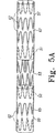
別の例において、可撓性ブリッジは接続されたジグザグステントの部分である部分的ステントである。この例において可撓性ブリッジは、ステントグラフト部分の各々の中央開口部に位置する各内部ステントと一体化している。図5Aを参照して、内部ステント50および51、ならびに可撓性ブリッジ53の部分的ステントは、接続された単一のジグザ
グステントの一体的部分である。内部ステントはグラフト材料55および57で覆われている。ステントグラフト部分65および67は各々中央開口部から離れた追加的Zステント62を有してもよく、これらのステントは内部でも外部でもよい。図5Bを参照して、内部ステント75および76はグラフト材料55および57で覆われており、それぞれのステントグラフト部分78および79の中央開口部から終端開口部まで延在する。これらの内部ステントと可撓性ブリッジ77の部分的ステントとは、接続された単一のジグザグステントの一体的部分である。
In another example, the flexible bridge is a partial stent that is part of a connected zigzag stent. In this example, the flexible bridge is integral with each internal stent located in each central opening of the stent graft portion. Referring to FIG. 5A, the
可撓性ブリッジおよびステントグラフト部分の各々の寸法は、人工器官の使用意図によって決定される。理想的には、相互接続されたレッグ延長人工器官の各部分、および相互接続されたレッグ延長人工器官が構成要素となる人工器官アセンブリの各構成要素は、処置される血管構造に人工器官アセンブリが最適に適合するように、正確に構築される。血管構造の寸法は、術中血管内超音波(IVUS)、コンピュータ断層撮影装置(CT)などの放射線学的方法、磁気共鳴映像法(MRI)、血管造影法を含むさまざまな方法によって決定され得る。相互接続された人工器官は、一定範囲で別々のサイズになるよう構築されてもよい。このように、相互接続されたレッグ延長人工器官は、緊急処置用の他の保管器具とともに使用するために在庫保管することができる。この一般的なタイプのシステムは、例えば米国特許出願公開番号第2002/0198587A1号に記載される。 The dimensions of each of the flexible bridge and stent graft portion are determined by the intended use of the prosthesis. Ideally, each part of the interconnected leg extension prosthesis, and each component of the prosthesis assembly that is a component of the interconnected leg extension prosthesis, has the prosthesis assembly in the vascular structure to be treated. Accurately constructed to fit optimally. The dimensions of the vasculature can be determined by various methods including intraoperative intravascular ultrasound (IVUS), radiological methods such as computed tomography (CT), magnetic resonance imaging (MRI), angiography. The interconnected prostheses may be constructed to have different sizes over a range. In this way, the interconnected leg extension prosthesis can be stocked for use with other storage devices for emergency treatment. This general type of system is described, for example, in US Patent Application Publication No. 2002 / 0198587A1.
相互接続されたレッグ延長人工器官の用途の可能性の1つは、大動脈瘤の処置のための人工器官アセンブリの構成要素としての使用である。このようなアセンブリは相互接続されたレッグ延長人工器官と、近位開口部および2つの遠位開口部を備えた主要管状本体を有する分岐した人工器官とを含み得る。分岐した人工器官の主要管状本体は、人工器官の近位開口部の近くで動脈瘤の上部の健康な組織に取付けられるように意図される。主要管状本体の遠位端の2つの開口部は、各遠位開口部が腸骨枝動脈のうちの1つの上または中にあるように、腸骨の分岐部にわたって適合する分岐部を形成する。このような分岐した人工器官の例は、W098/53761に記載されている。 One possible application of the interconnected leg extension prosthesis is its use as a component of a prosthetic assembly for the treatment of an aortic aneurysm. Such an assembly may include an interconnected leg extension prosthesis and a bifurcated prosthesis having a main tubular body with a proximal opening and two distal openings. The main tubular body of the bifurcated prosthesis is intended to be attached to the healthy tissue above the aneurysm near the proximal opening of the prosthesis. The two openings at the distal end of the main tubular body form a bifurcation that fits over the iliac bifurcation such that each distal opening is on or in one of the iliac branch arteries. . An example of such a branched prosthesis is described in W098 / 53761.
大動脈瘤の処置では、相互接続されたレッグ延長人工器官の所望の寸法は、腸骨動脈の寸法および状態(すなわち健康か動脈瘤があるか)、ならびにレッグ延長部と連係する分岐した人工器官の寸法によって決定される。図1を再び参照して、この例において、ステントグラフト部分の直径30または31は典型的には8mmから24mmまでの範囲であって、長さ35または36は典型的には15mmから125mmまでの範囲である。この例のステントグラフト部分の中央開口部の間の距離38は、典型的には30mmから60mmまでの範囲である。2つ以上の個別のステントまたはステントセグメントを含むステントグラフト部分については、ステントグラフトの軸に沿ったステントの間隔39は好ましくは0mmから8mmまである。
For aortic aneurysm treatment, the desired dimensions of the interconnected leg extension prosthesis include the dimensions and condition of the iliac arteries (ie, whether there is health or an aneurysm), and the bifurcated prosthesis associated with the leg extension. Determined by dimensions. Referring again to FIG. 1, in this example, the diameter 30 or 31 of the stent graft portion typically ranges from 8 mm to 24 mm and the
大動脈瘤処置用の分岐した人工器官の具体的な1つの例は、クック社(COOK、INK)から入手可能なZENITH(登録商標)AAA人工器官システムであり、それはW098/53761に一般に記載される。図6を参照して、この種の分岐した人工器官100は、近位開口部104を備えた主要管状本体102を有し、分岐部110において2つの遠位管状レッグ106および108を有する。ステント112は近位開口部104近くのグラフト材料に取付けられてそこから延在する。このステントは羽枝114を含み、動脈瘤の上部で人工器官の固定をもたらす。長い方の遠位レッグ106は、典型的に同側性の腸骨動脈に配置され、短い方の遠位レッグ108は典型的には対側性の腸骨動脈に配置される。短い方のレッグは、分岐部と遠位開口部109との間に1つの外部ジグザグステント111を含み、長い方のレッグは、分岐部と遠位開口部107との間に2つの外部ジグザグステント111を含む。
One specific example of a bifurcated prosthesis for treating an aortic aneurysm is the ZENITH® AAA prosthetic system available from Cook, Inc., which is generally described in W098 / 53761. . Referring to FIG. 6, this type of bifurcated prosthesis 100 has a main
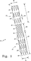
図6の分岐した人工器官と共に特に用いるための相互接続されたレッグ延長人工器官80の例が、図7に示される。この例は、長いステントグラフト部分81および短いステントグラフト部分82を有する。これらのステントグラフト部分は、分岐した人工器官の短い方のレッグおよび長い方のレッグをそれぞれ係合するよう設計される。長い方のステントグラフト部分は、中央開口部85の近くに内部ステント83を含み、部分の長さに沿って3つの外部ステント84を含む。短い方のステントグラフト部分は、中央開口部88の近くに内部ステント86を含み、部分の長さに沿って2つの外部ステント87を含む。各ステントグラフト部分の終端部90または91は内部ステントまたは外部ステントのいずれかを含むことができる。ステントグラフト部分の終端部については内部ステントが好ましい。なぜならこれが血管壁と人工器官との間の封止を強化し得るからである。
An example of an interconnected
図7をなお参照すると、可撓性ブリッジ95が曲がった形状で示され、処置部位に配置された時の人工器官のあり得る構成を例示する。可撓性ブリッジは中央開口部において内部ステントの各々に撤回不能に取付けられる。これらの中央開口部は、配置後各ステントグラフト部分の近位開口部として機能し、分岐した人工器官の遠位開口部と連係することが意図される。 Still referring to FIG. 7, the flexible bridge 95 is shown in a bent shape, illustrating a possible configuration of the prosthesis when placed at the treatment site. A flexible bridge is non-retractably attached to each of the inner stents at the central opening. These central openings function as proximal openings for each stent graft portion after deployment and are intended to be associated with the distal openings of the bifurcated prosthesis.
ステントグラフト部分の長さ、および部分内に含まれるステントの数は個別に変えることができる。例えば図8を参照して、分岐した人工器官150は長い遠位レッグ156および短い遠位レッグ158を有する。この分岐した人工器官と共に用いる相互接続されたレッグ延長人工器官160は、短いステントグラフト部分166および長いステントグラフト部分168を有することができる。好ましくは、短い方のステントグラフト部分は、中央開口部で少なくとも1つの内部ステントを含み、終端開口部で別の内部ステントを含む。図7に示される相互接続されたレッグ延長人工器官80は、処置要件に依存して、分岐した人工器官150と共に使用することもできる。
The length of the stent graft portion and the number of stents contained within the portion can vary individually. For example, referring to FIG. 8, a
相互接続されたレッグ延長人工器官は、さまざまな血管内技術を用いて処置部位に送達することができる。大動脈瘤を処置する際に、カテーテルベースのイントロデューサを用いて圧縮した人工器官を体内に挿入し、次に大腿動脈を通って大動脈に挿入することができる。イントロデューサは、WO03/53761およびUS2002/0198587に記載されたものに類似してもよい。 The interconnected leg extension prosthesis can be delivered to the treatment site using a variety of endovascular techniques. In treating an aortic aneurysm, a prosthesis compressed with a catheter-based introducer can be inserted into the body and then inserted through the femoral artery into the aorta. The introducer may be similar to those described in WO03 / 53761 and US2002 / 0198587.
図9を参照して、相互接続されたレッグ延長人工器官201用のイントロデューサ200の例は、送達シース202と、近位端206におけるテーパ状拡張器204と、送達システムの遠位端210におけるフィッティング208とを含む。ハンドル216に接続された内部カニューレ214は、テーパ状拡張器204から遠位端210まで全体に延在する。人工器官の配置に先立って抗凝固性ヘパリンまたは他の助剤を染み込ませ、および配置後に任意で造影剤または他の助剤を注入するために、注入システム212がフィッティング208の側面に連結される。
Referring to FIG. 9, an example of an
図9をなお参照して、イントロデューサ200はさらにチェックフローバルブ226、プッシャ228、プッシャフィッティング230、およびピンバイス232を含み、それらはすべて保護管234で覆われている。保護管234は操作中に遠位端の構成要素を覆い、使用前に取除かれる。タブ220が短いシース222の遠位端に与えられ、使用前にシースを剥がす。シース222は、出荷中および操作中にチェックフローバルブにおいてイントロデューサ内腔の開通性を保護し、フィッティング208内のみに延在する。スタイレット224は、カニューレ214、プッシャ228、およびイントロデューサシース202を通って、テーパ状拡張器204の近位端から突出する近位先端部205まで延在する。スタイレット224もまた出荷中および操作中に保護的に働き、同じく医学処置における使用前に取除かれる。
Still referring to FIG. 9, the
図10の断面図を参照して、送達システム300は、同側の腸骨動脈350を通って、主要大動脈に配置された分岐した人工器官301の遠位開口部307の中へ挿入されることにより、送達シース302において患者に導入される。その後内部カニューレが鋭角に曲がり、対側性の動脈351を下って分岐した人工器官の他方の遠位開口部309を通過するように拡張器304を方向付ける。この時点で、ステントグラフト部分320の圧縮された中央開口部324はレッグ308の遠位部分内にあり、ステントグラフト部分322の圧縮された中央開口部326はレッグ306の遠位部分内にあり、可撓性ブリッジ332は鋭角に曲がっている。その後、送達シース302が送達システムの遠位端に向けて引き戻され、ステントグラフト部分320の終端開口部328および中央開口部324、可撓性ブリッジ332、ならびにステントグラフト部分の中央開口部326および終端開口部330を連続的に解放する。
Referring to the cross-sectional view of FIG. 10, the
図11を参照して、人工器官の各ステントグラフト部分が解放されるとともにその部分は自己拡張し、分岐した人工器官の内面または腸骨動脈の血管壁に対して押付けられ得る。中央開口部部分324および326は、レッグ306および308の遠位部分に対して拡張して、ステントグラフト部分と分岐した人工器官との間に摩擦嵌めを確立する。したがってステントグラフト部分320および322は人工器官アセンブリ用のレッグ延長部として機能し、中央開口部324および326はレッグの近位端として機能する。終端開口部328および330は腸骨動脈の血管壁を係合し、レッグの遠位端として機能する。移植部位における人工器官の結合、および分岐した人工器官と血管壁とに対するその封止的係合は、各部位で成型バルーンを膨らませて人工器官を一杯に拡張させ、分岐した人工器官および/または血管壁に対して押し付けることにより、さらに強化され得る。
Referring to FIG. 11, each stent graft portion of the prosthesis is released and the portion self-expands and can be pressed against the inner surface of the bifurcated prosthesis or the vessel wall of the iliac artery.
図11から明らかなように、可撓性ブリッジは主要人工器官内で分岐部にわたって曲がり、各ステントグラフト部分のグラフト材料は主要人工器官のグラフト材料に重なる。両方のレッグ延長部はともに相互接続された単一の構成要素の一部であるので、完全な人工器官アセンブリの送達が簡単になる。さらに、この人工器官システムは、2つの腸骨レッグステントグラフトの力が釣り合うので、レッグ延長部が分離する危険を減じる。 As is apparent from FIG. 11, the flexible bridge bends across the bifurcation within the main prosthesis, and the graft material of each stent graft portion overlaps the graft material of the main prosthesis. Since both leg extensions are part of a single component interconnected together, delivery of a complete prosthetic assembly is simplified. In addition, this prosthetic system reduces the risk of leg extensions separating because the forces of the two iliac leg stent grafts are balanced.
本願明細書の全体にわたって、発明の範囲に関してさまざまな例示が与えられたが、本発明はこれらのうちのいずれにも限定されるのではなく、それらの2つ以上が組合されたものに存在し得る。例は限定ではなく例示のためにのみ挙げられる。 Throughout this specification, various examples have been given regarding the scope of the invention, but the invention is not limited to any of these, but exists in a combination of two or more thereof. obtain. The examples are given for illustration only and not for limitation.
Claims (8)
単一の近位開口部(104)ならびに第1および第2の遠位管状レッグ(106,108)を分岐部(110)に有する主要管状本体(102)を含む分岐した人工器官(150)を含み、第1の遠位管状レッグは第1の遠位開口部(107)を有し、第2の遠位管状レッグ(106)は第2の遠位開口部(109)を有し、腔内人工器官アセンブリはさらに、
第1のステントグラフト(81)、第2のステントグラフト(82)、ならびに、第1のステントグラフトおよび第2のステントグラフトの各々の端部の外周の一部に沿って第1のステントグラフトおよび第2のステントグラフト(81,82)の間に延在し、第1のステントグラフトおよび第2のステントグラフトに接続された、可撓性ブリッジ(95)を含む延長人工器官(160)を含み、
第1のステントグラフト(81)は、第2の遠位開口部(109)を係合するようサイズ決めされて構成され、第2のステントグラフトは、第1の遠位開口部(107)を係合するようサイズ決めされて構成され、可撓性ブリッジは、第1および第2のステントグラフトが分岐した人工器官のためのレッグ延長部として機能するように主要管状本体の分岐部にわたって曲げることができる、腔内人工器官アセンブリ。An endoluminal prosthesis assembly comprising:
A bifurcated prosthesis ( 150) comprising a main tubular body (102) having a single proximal opening (104) and first and second distal tubular legs (106, 108) in the bifurcation (110). A first distal tubular leg having a first distal opening (107) and a second distal tubular leg (106) having a second distal opening (109); The endoprosthesis assembly further includes
A first stent graft (81), a second stent graft (82), and a first stent graft and a second stent graft along a portion of the outer circumference of each end of the first stent graft and the second stent graft ( extends between 81 and 82), connected to the first stent graft and the second stent graft, the extension prosthesis (the 160) viewed contains include a flexible bridge (95),
The first stent graft (81) is sized and configured to engage the second distal opening (109), and the second stent graft engages the first distal opening (107). Sized and configured so that the flexible bridge can be bent over the bifurcation of the main tubular body so that the first and second stent grafts function as leg extensions for the bifurcated prosthesis , Intracavity prosthesis assembly.
ンブリ。The first stent graft (81) is longer than the second stent graft (82), the first stent graft is sized and configured to engage the distal opening of the shorter stent graft leg, and the second stent graft is 4. The endoluminal prosthesis assembly of claim 3 , wherein the endoprosthesis assembly is sized and configured to engage a distal opening of a longer stent graph leg.
Applications Claiming Priority (2)
| Application Number | Priority Date | Filing Date | Title |
|---|---|---|---|
| US53038803P | 2003-12-17 | 2003-12-17 | |
| PCT/US2004/042298 WO2005058202A1 (en) | 2003-12-17 | 2004-12-16 | Interconnected leg extensions for an endoluminal prostehsis |
Publications (3)
| Publication Number | Publication Date |
|---|---|
| JP2007514498A JP2007514498A (en) | 2007-06-07 |
| JP2007514498A5 JP2007514498A5 (en) | 2008-01-17 |
| JP4464972B2 true JP4464972B2 (en) | 2010-05-19 |
Family
ID=34700132
Family Applications (1)
| Application Number | Title | Priority Date | Filing Date |
|---|---|---|---|
| JP2006545438A Active JP4464972B2 (en) | 2003-12-17 | 2004-12-16 | Interconnected leg extensions for endoluminal prostheses |
Country Status (7)
| Country | Link |
|---|---|
| US (1) | US8257430B2 (en) |
| EP (1) | EP1696828B1 (en) |
| JP (1) | JP4464972B2 (en) |
| AT (1) | ATE478629T1 (en) |
| AU (1) | AU2004299108B2 (en) |
| DE (1) | DE602004028863D1 (en) |
| WO (1) | WO2005058202A1 (en) |
Families Citing this family (73)
| Publication number | Priority date | Publication date | Assignee | Title |
|---|---|---|---|---|
| US20040267349A1 (en) | 2003-06-27 | 2004-12-30 | Kobi Richter | Amorphous metal alloy medical devices |
| US8382821B2 (en) | 1998-12-03 | 2013-02-26 | Medinol Ltd. | Helical hybrid stent |
| US20060122691A1 (en) * | 1998-12-03 | 2006-06-08 | Jacob Richter | Hybrid stent |
| US8038708B2 (en) | 2001-02-05 | 2011-10-18 | Cook Medical Technologies Llc | Implantable device with remodelable material and covering material |
| US7147661B2 (en) | 2001-12-20 | 2006-12-12 | Boston Scientific Santa Rosa Corp. | Radially expandable stent |
| US9155639B2 (en) | 2009-04-22 | 2015-10-13 | Medinol Ltd. | Helical hybrid stent |
| US9039755B2 (en) | 2003-06-27 | 2015-05-26 | Medinol Ltd. | Helical hybrid stent |
| US11596537B2 (en) | 2003-09-03 | 2023-03-07 | Bolton Medical, Inc. | Delivery system and method for self-centering a proximal end of a stent graft |
| US7763063B2 (en) | 2003-09-03 | 2010-07-27 | Bolton Medical, Inc. | Self-aligning stent graft delivery system, kit, and method |
| US11259945B2 (en) | 2003-09-03 | 2022-03-01 | Bolton Medical, Inc. | Dual capture device for stent graft delivery system and method for capturing a stent graft |
| US8292943B2 (en) | 2003-09-03 | 2012-10-23 | Bolton Medical, Inc. | Stent graft with longitudinal support member |
| US20080264102A1 (en) | 2004-02-23 | 2008-10-30 | Bolton Medical, Inc. | Sheath Capture Device for Stent Graft Delivery System and Method for Operating Same |
| US8500792B2 (en) | 2003-09-03 | 2013-08-06 | Bolton Medical, Inc. | Dual capture device for stent graft delivery system and method for capturing a stent graft |
| US9198786B2 (en) | 2003-09-03 | 2015-12-01 | Bolton Medical, Inc. | Lumen repair device with capture structure |
| US20070198078A1 (en) * | 2003-09-03 | 2007-08-23 | Bolton Medical, Inc. | Delivery system and method for self-centering a Proximal end of a stent graft |
| WO2005067817A1 (en) | 2004-01-13 | 2005-07-28 | Remon Medical Technologies Ltd | Devices for fixing a sensor in a body lumen |
| US7674284B2 (en) * | 2004-03-31 | 2010-03-09 | Cook Incorporated | Endoluminal graft |
| KR100601969B1 (en) * | 2004-06-15 | 2006-07-14 | 주식회사 에스앤지바이오텍 | Artificial blood vessel stent |
| US10390714B2 (en) | 2005-01-12 | 2019-08-27 | Remon Medical Technologies, Ltd. | Devices for fixing a sensor in a lumen |
| AU2006269444B2 (en) * | 2005-07-07 | 2011-07-21 | Cook Medical Technologies Llc | Branch vessel stent graft |
| US20100070043A1 (en) * | 2005-08-04 | 2010-03-18 | Kitchen Michael S | Shape memory orthopedic joint |
| GB0517085D0 (en) * | 2005-08-19 | 2005-09-28 | Angiomed Ag | Polymer prosthesis |
| WO2007040249A1 (en) * | 2005-10-06 | 2007-04-12 | Kaneka Corporation | Stent to be placed in the living body |
| US7670369B2 (en) * | 2005-10-13 | 2010-03-02 | Cook Incorporated | Endoluminal prosthesis |
| US20070106375A1 (en) * | 2005-11-07 | 2007-05-10 | Carlos Vonderwalde | Bifurcated stent assembly |
| JP5067891B2 (en) * | 2005-11-15 | 2012-11-07 | レモン メディカル テクノロジーズ リミテッド | Implantable device for securing a sensor to a body lumen |
| US8840657B2 (en) * | 2006-01-18 | 2014-09-23 | Cook Medical Technologies Llc | Self expanding stent |
| WO2007100716A2 (en) * | 2006-02-27 | 2007-09-07 | William A. Cook Australia Pty. Ltd. | Retention of stents |
| US8676349B2 (en) | 2006-09-15 | 2014-03-18 | Cardiac Pacemakers, Inc. | Mechanism for releasably engaging an implantable medical device for implantation |
| EP2162185B1 (en) | 2007-06-14 | 2015-07-01 | Cardiac Pacemakers, Inc. | Multi-element acoustic recharging system |
| US8066755B2 (en) | 2007-09-26 | 2011-11-29 | Trivascular, Inc. | System and method of pivoted stent deployment |
| US8663309B2 (en) * | 2007-09-26 | 2014-03-04 | Trivascular, Inc. | Asymmetric stent apparatus and method |
| US8226701B2 (en) * | 2007-09-26 | 2012-07-24 | Trivascular, Inc. | Stent and delivery system for deployment thereof |
| CN101917929A (en) | 2007-10-04 | 2010-12-15 | 特里瓦斯库拉尔公司 | Modular vascular graft for low profile percutaneous delivery |
| US8328861B2 (en) * | 2007-11-16 | 2012-12-11 | Trivascular, Inc. | Delivery system and method for bifurcated graft |
| US8083789B2 (en) | 2007-11-16 | 2011-12-27 | Trivascular, Inc. | Securement assembly and method for expandable endovascular device |
| WO2009102439A1 (en) | 2008-02-11 | 2009-08-20 | William Cook Europe Aps | Prosthesis coupling device and method |
| US10028747B2 (en) | 2008-05-01 | 2018-07-24 | Aneuclose Llc | Coils with a series of proximally-and-distally-connected loops for occluding a cerebral aneurysm |
| US10716573B2 (en) | 2008-05-01 | 2020-07-21 | Aneuclose | Janjua aneurysm net with a resilient neck-bridging portion for occluding a cerebral aneurysm |
| CN107961098A (en) | 2008-06-30 | 2018-04-27 | 波顿医疗公司 | System and method for abdominal aneurvsm |
| JP5362828B2 (en) | 2008-07-15 | 2013-12-11 | カーディアック ペースメイカーズ, インコーポレイテッド | Implant assist for an acoustically enabled implantable medical device |
| US20100049307A1 (en) * | 2008-08-25 | 2010-02-25 | Aga Medical Corporation | Stent graft having extended landing area and method for using the same |
| US8694129B2 (en) | 2009-02-13 | 2014-04-08 | Cardiac Pacemakers, Inc. | Deployable sensor platform on the lead system of an implantable device |
| EP3284447B1 (en) | 2009-03-13 | 2020-05-20 | Bolton Medical Inc. | System for deploying an endoluminal prosthesis at a surgical site |
| CN102740807B (en) | 2009-11-30 | 2015-11-25 | 恩多斯潘有限公司 | For implantation into the multi-part overlay film frame system had in the blood vessel of multiple branch |
| WO2011070576A1 (en) * | 2009-12-08 | 2011-06-16 | Endospan Ltd. | Endovascular stent-graft system with fenestrated and crossing stent-grafts |
| US20120029611A1 (en) * | 2010-07-28 | 2012-02-02 | Medtronic Vascular, Inc. | Stent Graft System and Method of Use |
| US9707108B2 (en) * | 2010-11-24 | 2017-07-18 | Tryton Medical, Inc. | Support for treating vascular bifurcations |
| US10335296B2 (en) * | 2011-05-17 | 2019-07-02 | The University Of Kentucky Research Foundation | Graft within a graft endoluminal graft |
| EP2729095B1 (en) | 2011-07-07 | 2016-10-26 | Endospan Ltd. | Stent fixation with reduced plastic deformation |
| WO2013071222A1 (en) | 2011-11-11 | 2013-05-16 | Parodi Juan C | Universal endovascular grafts |
| ES2625629T7 (en) | 2011-11-16 | 2017-12-19 | Bolton Medical Inc. | Device for the repair of the bifurcated aortic vessel |
| DE102012100839A1 (en) | 2012-02-01 | 2013-08-01 | Jotec Gmbh | Intraluminal vascular prosthesis |
| US8992595B2 (en) | 2012-04-04 | 2015-03-31 | Trivascular, Inc. | Durable stent graft with tapered struts and stable delivery methods and devices |
| US9498363B2 (en) | 2012-04-06 | 2016-11-22 | Trivascular, Inc. | Delivery catheter for endovascular device |
| WO2013154749A1 (en) | 2012-04-12 | 2013-10-17 | Bolton Medical, Inc. | Vascular prosthetic delivery device and method of use |
| US9668892B2 (en) | 2013-03-11 | 2017-06-06 | Endospan Ltd. | Multi-component stent-graft system for aortic dissections |
| US9439751B2 (en) | 2013-03-15 | 2016-09-13 | Bolton Medical, Inc. | Hemostasis valve and delivery systems |
| CN105744913A (en) * | 2013-09-19 | 2016-07-06 | 曼霍勒公司 | Systems and methods for deploying a luminal prostheses over a carina |
| WO2015075708A1 (en) | 2013-11-19 | 2015-05-28 | Endospan Ltd. | Stent system with radial-expansion locking |
| US10524893B2 (en) | 2014-09-23 | 2020-01-07 | Bolton Medical, Inc. | Vascular repair devices and methods of use |
| EP3068339B1 (en) | 2014-12-18 | 2017-11-01 | Endospan Ltd. | Endovascular stent-graft with fatigue-resistant lateral tube |
| EP3653177B1 (en) | 2015-01-11 | 2021-09-01 | Ascyrus Medical, LLC | Hybrid device for surgical aortic repair |
| US10512533B1 (en) | 2016-02-23 | 2019-12-24 | W. L. Gore & Associates, Inc. | Branched graft assembly method in vivo |
| WO2017176730A1 (en) | 2016-04-05 | 2017-10-12 | Bolton Medical, Inc. | Stent graft with internal tunnels and fenestrations and methods of use |
| US9987122B2 (en) | 2016-04-13 | 2018-06-05 | Medtronic Vascular, Inc. | Iliac branch device and method |
| EP3463184B1 (en) | 2016-05-25 | 2021-12-22 | Bolton Medical, Inc. | Stent grafts for treating aneurysms |
| EP3524175A4 (en) * | 2016-10-10 | 2020-10-14 | Jeng Wei | Blood conduit with stent |
| WO2018156717A1 (en) * | 2017-02-24 | 2018-08-30 | The Cleveland Clinic Foundation | Method and apparatus for time-differential deployment of an endovascular device within a body lumen |
| CN106983581A (en) * | 2017-04-20 | 2017-07-28 | 江门市众新思创医疗科技有限公司 | A kind of Intravascular stent for aorta |
| CN107296668A (en) * | 2017-08-01 | 2017-10-27 | 有研医疗器械(北京)有限公司 | A kind of non-film-coated vascular support and its method for releasing |
| JP2022525788A (en) | 2019-03-20 | 2022-05-19 | インキュベート メディカル テクノロジーズ、 エルエルシー | Aortic dissection implant |
| CN111067664B (en) * | 2019-12-25 | 2022-07-05 | 先健科技(深圳)有限公司 | Covered stent |
Family Cites Families (93)
| Publication number | Priority date | Publication date | Assignee | Title |
|---|---|---|---|---|
| US4994071A (en) | 1989-05-22 | 1991-02-19 | Cordis Corporation | Bifurcating stent apparatus and method |
| CA2026604A1 (en) * | 1989-10-02 | 1991-04-03 | Rodney G. Wolff | Articulated stent |
| US5135536A (en) | 1991-02-05 | 1992-08-04 | Cordis Corporation | Endovascular stent and method |
| US5628783A (en) | 1991-04-11 | 1997-05-13 | Endovascular Technologies, Inc. | Bifurcated multicapsule intraluminal grafting system and method |
| CA2065634C (en) | 1991-04-11 | 1997-06-03 | Alec A. Piplani | Endovascular graft having bifurcation and apparatus and method for deploying the same |
| US5316023A (en) | 1992-01-08 | 1994-05-31 | Expandable Grafts Partnership | Method for bilateral intra-aortic bypass |
| DE69419877T2 (en) | 1993-11-04 | 1999-12-16 | Bard Inc C R | Fixed vascular prosthesis |
| DE9319267U1 (en) | 1993-12-15 | 1994-02-24 | Vorwerk Dierk Dr | Aortic endoprosthesis |
| US6051020A (en) | 1994-02-09 | 2000-04-18 | Boston Scientific Technology, Inc. | Bifurcated endoluminal prosthesis |
| US5609627A (en) | 1994-02-09 | 1997-03-11 | Boston Scientific Technology, Inc. | Method for delivering a bifurcated endoluminal prosthesis |
| US6039749A (en) | 1994-02-10 | 2000-03-21 | Endovascular Systems, Inc. | Method and apparatus for deploying non-circular stents and graftstent complexes |
| US5507769A (en) | 1994-10-18 | 1996-04-16 | Stentco, Inc. | Method and apparatus for forming an endoluminal bifurcated graft |
| US5683451A (en) | 1994-06-08 | 1997-11-04 | Cardiovascular Concepts, Inc. | Apparatus and methods for deployment release of intraluminal prostheses |
| US5575817A (en) | 1994-08-19 | 1996-11-19 | Martin; Eric C. | Aorto femoral bifurcation graft and method of implantation |
| US5609605A (en) | 1994-08-25 | 1997-03-11 | Ethicon, Inc. | Combination arterial stent |
| NL9500094A (en) | 1995-01-19 | 1996-09-02 | Industrial Res Bv | Y-shaped stent and method of deployment. |
| US5683449A (en) | 1995-02-24 | 1997-11-04 | Marcade; Jean Paul | Modular bifurcated intraluminal grafts and methods for delivering and assembling same |
| US5709713A (en) | 1995-03-31 | 1998-01-20 | Cardiovascular Concepts, Inc. | Radially expansible vascular prosthesis having reversible and other locking structures |
| FR2733682B1 (en) | 1995-05-04 | 1997-10-31 | Dibie Alain | ENDOPROSTHESIS FOR THE TREATMENT OF STENOSIS ON BIFURCATIONS OF BLOOD VESSELS AND LAYING EQUIPMENT THEREFOR |
| US6602281B1 (en) * | 1995-06-05 | 2003-08-05 | Avantec Vascular Corporation | Radially expansible vessel scaffold having beams and expansion joints |
| US6033434A (en) | 1995-06-08 | 2000-03-07 | Ave Galway Limited | Bifurcated endovascular stent and methods for forming and placing |
| US5769882A (en) | 1995-09-08 | 1998-06-23 | Medtronic, Inc. | Methods and apparatus for conformably sealing prostheses within body lumens |
| US6193745B1 (en) | 1995-10-03 | 2001-02-27 | Medtronic, Inc. | Modular intraluminal prosteheses construction and methods |
| US5591195A (en) | 1995-10-30 | 1997-01-07 | Taheri; Syde | Apparatus and method for engrafting a blood vessel |
| US6576009B2 (en) | 1995-12-01 | 2003-06-10 | Medtronic Ave, Inc. | Bifurcated intraluminal prostheses construction and methods |
| US5824040A (en) | 1995-12-01 | 1998-10-20 | Medtronic, Inc. | Endoluminal prostheses and therapies for highly variable body lumens |
| US6878161B2 (en) | 1996-01-05 | 2005-04-12 | Medtronic Vascular, Inc. | Stent graft loading and deployment device and method |
| US6251133B1 (en) | 1996-05-03 | 2001-06-26 | Medinol Ltd. | Bifurcated stent with improved side branch aperture and method of making same |
| FR2749160B1 (en) | 1996-05-28 | 1999-05-21 | Patrice Bergeron | MODULAR BIFURCED VASCULAR PROSTHESIS |
| CA2227446A1 (en) | 1996-05-31 | 1997-12-04 | Bard Galway Limited | Bifurcated endovascular stents and method and apparatus for their placement |
| US5755773A (en) | 1996-06-04 | 1998-05-26 | Medtronic, Inc. | Endoluminal prosthetic bifurcation shunt |
| FR2749500B1 (en) | 1996-06-06 | 1998-11-20 | Jacques Seguin | DEVICE ALLOWING THE TREATMENT OF BODY DUCTS AT THE LEVEL OF A BIFURCATION |
| US6666883B1 (en) | 1996-06-06 | 2003-12-23 | Jacques Seguin | Endoprosthesis for vascular bifurcation |
| US5676697A (en) | 1996-07-29 | 1997-10-14 | Cardiovascular Dynamics, Inc. | Two-piece, bifurcated intraluminal graft for repair of aneurysm |
| US6325819B1 (en) | 1996-08-19 | 2001-12-04 | Cook Incorporated | Endovascular prosthetic device, an endovascular graft prothesis with such a device, and a method for repairing an abdominal aortic aneurysm |
| US5911732A (en) | 1997-03-10 | 1999-06-15 | Johnson & Johnson Interventional Systems, Co. | Articulated expandable intraluminal stent |
| GR970100134A (en) | 1997-04-10 | 1998-12-31 | Bifurcated inravascular implant for the intravascular treatment of aneurysms of the abdominal aorta and implanting technique | |
| US6245102B1 (en) | 1997-05-07 | 2001-06-12 | Iowa-India Investments Company Ltd. | Stent, stent graft and stent valve |
| AUPO700897A0 (en) | 1997-05-26 | 1997-06-19 | William A Cook Australia Pty Ltd | A method and means of deploying a graft |
| CA2235911C (en) * | 1997-05-27 | 2003-07-29 | Schneider (Usa) Inc. | Stent and stent-graft for treating branched vessels |
| US6102938A (en) | 1997-06-17 | 2000-08-15 | Medtronic Inc. | Endoluminal prosthetic bifurcation shunt |
| US5904713A (en) * | 1997-07-14 | 1999-05-18 | Datascope Investment Corp. | Invertible bifurcated stent/graft and method of deployment |
| US6070589A (en) | 1997-08-01 | 2000-06-06 | Teramed, Inc. | Methods for deploying bypass graft stents |
| US6361544B1 (en) | 1997-08-13 | 2002-03-26 | Advanced Cardiovascular Systems, Inc. | Stent and catheter assembly and method for treating bifurcations |
| US6165195A (en) | 1997-08-13 | 2000-12-26 | Advanced Cardiovascylar Systems, Inc. | Stent and catheter assembly and method for treating bifurcations |
| US6306164B1 (en) | 1997-09-05 | 2001-10-23 | C. R. Bard, Inc. | Short body endoprosthesis |
| DE69838256T2 (en) | 1997-09-24 | 2008-05-15 | Med Institute, Inc., West Lafayette | RADIAL EXPANDABLE STENT |
| US5893887A (en) | 1997-10-14 | 1999-04-13 | Iowa-India Investments Company Limited | Stent for positioning at junction of bifurcated blood vessel and method of making |
| US5961548A (en) | 1997-11-18 | 1999-10-05 | Shmulewitz; Ascher | Bifurcated two-part graft and methods of implantation |
| AUPP083597A0 (en) | 1997-12-10 | 1998-01-08 | William A Cook Australia Pty Ltd | Endoluminal aortic stents |
| US6129756A (en) | 1998-03-16 | 2000-10-10 | Teramed, Inc. | Biluminal endovascular graft system |
| US6524336B1 (en) | 1998-04-09 | 2003-02-25 | Cook Incorporated | Endovascular graft |
| US6093203A (en) | 1998-05-13 | 2000-07-25 | Uflacker; Renan | Stent or graft support structure for treating bifurcated vessels having different diameter portions and methods of use and implantation |
| US6143002A (en) | 1998-08-04 | 2000-11-07 | Scimed Life Systems, Inc. | System for delivering stents to bifurcation lesions |
| US6117117A (en) | 1998-08-24 | 2000-09-12 | Advanced Cardiovascular Systems, Inc. | Bifurcated catheter assembly |
| US6368345B1 (en) | 1998-09-30 | 2002-04-09 | Edwards Lifesciences Corporation | Methods and apparatus for intraluminal placement of a bifurcated intraluminal garafat |
| US6197049B1 (en) | 1999-02-17 | 2001-03-06 | Endologix, Inc. | Articulating bifurcation graft |
| US6022359A (en) * | 1999-01-13 | 2000-02-08 | Frantzen; John J. | Stent delivery system featuring a flexible balloon |
| US6200339B1 (en) * | 1999-02-23 | 2001-03-13 | Datascope Investment Corp. | Endovascular split-tube bifurcated graft prosthesis and an implantation method for such a prosthesis |
| US6258117B1 (en) * | 1999-04-15 | 2001-07-10 | Mayo Foundation For Medical Education And Research | Multi-section stent |
| US6409757B1 (en) | 1999-09-15 | 2002-06-25 | Eva Corporation | Method and apparatus for supporting a graft assembly |
| US6344056B1 (en) * | 1999-12-29 | 2002-02-05 | Edwards Lifesciences Corp. | Vascular grafts for bridging a vessel side branch |
| US20020198585A1 (en) | 1999-10-05 | 2002-12-26 | Willem Wisselink | System and method for edoluminal grafting of bifurcated or branched vessels |
| US6585758B1 (en) | 1999-11-16 | 2003-07-01 | Scimed Life Systems, Inc. | Multi-section filamentary endoluminal stent |
| US6673107B1 (en) * | 1999-12-06 | 2004-01-06 | Advanced Cardiovascular Systems, Inc. | Bifurcated stent and method of making |
| DE60118657T2 (en) * | 2000-02-07 | 2007-04-05 | S & G Biotech Inc. | BLOOD TISSUE PLANT AND TRANSPLANT INTRODUCER |
| ATE255860T1 (en) | 2000-03-03 | 2003-12-15 | Cook Inc | ENDOVASCULAR DEVICE WITH STENT |
| US6695875B2 (en) | 2000-03-14 | 2004-02-24 | Cook Incorporated | Endovascular stent graft |
| US6454796B1 (en) * | 2000-05-05 | 2002-09-24 | Endovascular Technologies, Inc. | Vascular graft |
| US20020042644A1 (en) | 2000-10-10 | 2002-04-11 | Greenhalgh E. Skott | Bifurcated fabric sleeve stent graft with junction region strengthening elements |
| WO2002067815A1 (en) | 2001-02-26 | 2002-09-06 | Scimed Life Systems, Inc. | Bifurcated stent |
| WO2002067653A2 (en) | 2001-02-26 | 2002-09-06 | Scimed Life Systems, Inc. | Bifurcated stent and delivery system |
| US6602225B2 (en) | 2001-02-28 | 2003-08-05 | Scimed Life Systems, Inc | Substantially circular catheter assembly |
| FR2822370B1 (en) | 2001-03-23 | 2004-03-05 | Perouse Lab | TUBULAR ENDOPROSTHESIS COMPRISING A DEFORMABLE RING AND REQUIRED OF INTERVENTION FOR ITS IMPLANTATION |
| ATE272369T1 (en) | 2001-03-27 | 2004-08-15 | Cook William Europ | VESSEL TRANSPLANT FOR THE AORTA |
| US6585753B2 (en) | 2001-03-28 | 2003-07-01 | Scimed Life Systems, Inc. | Expandable coil stent |
| US7160318B2 (en) | 2001-03-28 | 2007-01-09 | Cook Incorporated | Modular stent graft assembly and use thereof |
| US6949121B1 (en) | 2002-02-07 | 2005-09-27 | Sentient Engineering & Technology, Llc | Apparatus and methods for conduits and materials |
| WO2003082153A2 (en) | 2002-03-25 | 2003-10-09 | Cook Incorporated | Branched vessel prothesis |
| US7131991B2 (en) | 2002-04-24 | 2006-11-07 | Medtronic Vascular, Inc. | Endoluminal prosthetic assembly and extension method |
| US7655036B2 (en) * | 2002-04-24 | 2010-02-02 | Medtronic Vascular, Inc. | Bifurcated endoluminal prosthetic assembly and method |
| US7887575B2 (en) | 2002-05-22 | 2011-02-15 | Boston Scientific Scimed, Inc. | Stent with segmented graft |
| AU2003262754B2 (en) | 2002-08-23 | 2007-06-21 | Cook Incorporated | Composite prosthesis |
| AU2003295797B2 (en) | 2002-11-22 | 2009-01-29 | Cook Biotech, Inc. | Stent tissue graft prosthesis |
| US7314485B2 (en) | 2003-02-03 | 2008-01-01 | Cardiac Dimensions, Inc. | Mitral valve device using conditioned shape memory alloy |
| EP1608293B1 (en) | 2003-04-03 | 2015-06-03 | Cook Medical Technologies LLC | Deployment system for a branched stent graft |
| US7530995B2 (en) | 2003-04-17 | 2009-05-12 | 3F Therapeutics, Inc. | Device for reduction of pressure effects of cardiac tricuspid valve regurgitation |
| WO2004100836A1 (en) | 2003-05-12 | 2004-11-25 | Cook Incorporated | Stent graft |
| US20040243221A1 (en) | 2003-05-27 | 2004-12-02 | Fawzi Natalie V. | Endovascular graft including substructure for positioning and sealing within vasculature |
| US7674284B2 (en) | 2004-03-31 | 2010-03-09 | Cook Incorporated | Endoluminal graft |
| US7699883B2 (en) | 2004-10-25 | 2010-04-20 | Myles Douglas | Vascular graft and deployment system |
| US20060089704A1 (en) | 2004-10-25 | 2006-04-27 | Myles Douglas | Vascular graft and deployment system |
| CA2586018A1 (en) | 2004-11-03 | 2006-07-13 | Jacques Seguin | Vascular graft and deployment system |
-
2004
- 2004-12-16 WO PCT/US2004/042298 patent/WO2005058202A1/en not_active Application Discontinuation
- 2004-12-16 JP JP2006545438A patent/JP4464972B2/en active Active
- 2004-12-16 US US11/014,669 patent/US8257430B2/en active Active
- 2004-12-16 AU AU2004299108A patent/AU2004299108B2/en active Active
- 2004-12-16 DE DE602004028863T patent/DE602004028863D1/en active Active
- 2004-12-16 EP EP04814477A patent/EP1696828B1/en active Active
- 2004-12-16 AT AT04814477T patent/ATE478629T1/en not_active IP Right Cessation
Also Published As
| Publication number | Publication date |
|---|---|
| JP2007514498A (en) | 2007-06-07 |
| EP1696828B1 (en) | 2010-08-25 |
| AU2004299108A1 (en) | 2005-06-30 |
| AU2004299108B2 (en) | 2010-04-22 |
| WO2005058202A1 (en) | 2005-06-30 |
| DE602004028863D1 (en) | 2010-10-07 |
| US20050177222A1 (en) | 2005-08-11 |
| ATE478629T1 (en) | 2010-09-15 |
| US8257430B2 (en) | 2012-09-04 |
| EP1696828A1 (en) | 2006-09-06 |
Similar Documents
| Publication | Publication Date | Title |
|---|---|---|
| JP4464972B2 (en) | Interconnected leg extensions for endoluminal prostheses | |
| US7674284B2 (en) | Endoluminal graft | |
| US8002816B2 (en) | Prosthesis for implantation in aorta and method of using same | |
| US8915955B2 (en) | Stent graft fixation coupling | |
| US6652580B1 (en) | Modular, staged graft and attachment system for endovascular repair | |
| US7105020B2 (en) | Branched vessel endoluminal device | |
| US9974674B2 (en) | Branch vessel prothesis with positional indicator system and method | |
| US8343204B2 (en) | Composite stent graft | |
| US9687337B2 (en) | Locking mechanism for securing the interface between stent grafts | |
| US20110218617A1 (en) | Endoluminal vascular prosthesis | |
| US9510936B2 (en) | Stent element |
Legal Events
| Date | Code | Title | Description |
|---|---|---|---|
| A521 | Request for written amendment filed |
Free format text: JAPANESE INTERMEDIATE CODE: A523 Effective date: 20071119 |
|
| A621 | Written request for application examination |
Free format text: JAPANESE INTERMEDIATE CODE: A621 Effective date: 20071119 |
|
| A131 | Notification of reasons for refusal |
Free format text: JAPANESE INTERMEDIATE CODE: A131 Effective date: 20091020 |
|
| A977 | Report on retrieval |
Free format text: JAPANESE INTERMEDIATE CODE: A971007 Effective date: 20091022 |
|
| A521 | Request for written amendment filed |
Free format text: JAPANESE INTERMEDIATE CODE: A523 Effective date: 20100105 |
|
| TRDD | Decision of grant or rejection written | ||
| A01 | Written decision to grant a patent or to grant a registration (utility model) |
Free format text: JAPANESE INTERMEDIATE CODE: A01 Effective date: 20100202 |
|
| A01 | Written decision to grant a patent or to grant a registration (utility model) |
Free format text: JAPANESE INTERMEDIATE CODE: A01 |
|
| A61 | First payment of annual fees (during grant procedure) |
Free format text: JAPANESE INTERMEDIATE CODE: A61 Effective date: 20100219 |
|
| FPAY | Renewal fee payment (event date is renewal date of database) |
Free format text: PAYMENT UNTIL: 20130226 Year of fee payment: 3 |
|
| R150 | Certificate of patent or registration of utility model |
Free format text: JAPANESE INTERMEDIATE CODE: R150 Ref document number: 4464972 Country of ref document: JP Free format text: JAPANESE INTERMEDIATE CODE: R150 |
|
| FPAY | Renewal fee payment (event date is renewal date of database) |
Free format text: PAYMENT UNTIL: 20130226 Year of fee payment: 3 |
|
| FPAY | Renewal fee payment (event date is renewal date of database) |
Free format text: PAYMENT UNTIL: 20140226 Year of fee payment: 4 |
|
| R250 | Receipt of annual fees |
Free format text: JAPANESE INTERMEDIATE CODE: R250 |
|
| R250 | Receipt of annual fees |
Free format text: JAPANESE INTERMEDIATE CODE: R250 |
|
| R250 | Receipt of annual fees |
Free format text: JAPANESE INTERMEDIATE CODE: R250 |
|
| R250 | Receipt of annual fees |
Free format text: JAPANESE INTERMEDIATE CODE: R250 |
|
| R250 | Receipt of annual fees |
Free format text: JAPANESE INTERMEDIATE CODE: R250 |
|
| R250 | Receipt of annual fees |
Free format text: JAPANESE INTERMEDIATE CODE: R250 |
|
| R250 | Receipt of annual fees |
Free format text: JAPANESE INTERMEDIATE CODE: R250 |
|
| R250 | Receipt of annual fees |
Free format text: JAPANESE INTERMEDIATE CODE: R250 |
|
| R250 | Receipt of annual fees |
Free format text: JAPANESE INTERMEDIATE CODE: R250 |
|
| R250 | Receipt of annual fees |
Free format text: JAPANESE INTERMEDIATE CODE: R250 |
|
| R250 | Receipt of annual fees |
Free format text: JAPANESE INTERMEDIATE CODE: R250 |