EP2348950B1 - Endoskopendkappe zum nähen von gewebe - Google Patents
Endoskopendkappe zum nähen von gewebe Download PDFInfo
- Publication number
- EP2348950B1 EP2348950B1 EP09745205.6A EP09745205A EP2348950B1 EP 2348950 B1 EP2348950 B1 EP 2348950B1 EP 09745205 A EP09745205 A EP 09745205A EP 2348950 B1 EP2348950 B1 EP 2348950B1
- Authority
- EP
- European Patent Office
- Prior art keywords
- interior space
- tissue
- sidewall
- side port
- medical device
- Prior art date
- Legal status (The legal status is an assumption and is not a legal conclusion. Google has not performed a legal analysis and makes no representation as to the accuracy of the status listed.)
- Active
Links
- 238000004891 communication Methods 0.000 claims description 7
- 238000012800 visualization Methods 0.000 claims description 6
- 239000000463 material Substances 0.000 claims description 4
- 210000001519 tissue Anatomy 0.000 description 85
- 238000000034 method Methods 0.000 description 14
- 210000001035 gastrointestinal tract Anatomy 0.000 description 6
- 229920003023 plastic Polymers 0.000 description 5
- 239000004033 plastic Substances 0.000 description 5
- 238000012986 modification Methods 0.000 description 3
- 230000004048 modification Effects 0.000 description 3
- 210000000214 mouth Anatomy 0.000 description 3
- 210000003200 peritoneal cavity Anatomy 0.000 description 3
- 241001465754 Metazoa Species 0.000 description 2
- 210000003484 anatomy Anatomy 0.000 description 2
- 210000000436 anus Anatomy 0.000 description 2
- 238000010276 construction Methods 0.000 description 2
- 229920001971 elastomer Polymers 0.000 description 2
- 239000004744 fabric Substances 0.000 description 2
- 230000002496 gastric effect Effects 0.000 description 2
- 210000003736 gastrointestinal content Anatomy 0.000 description 2
- 208000015181 infectious disease Diseases 0.000 description 2
- 210000002784 stomach Anatomy 0.000 description 2
- 210000001215 vagina Anatomy 0.000 description 2
- 241000894006 Bacteria Species 0.000 description 1
- 239000004698 Polyethylene Substances 0.000 description 1
- 230000003187 abdominal effect Effects 0.000 description 1
- NIXOWILDQLNWCW-UHFFFAOYSA-N acrylic acid group Chemical group C(C=C)(=O)O NIXOWILDQLNWCW-UHFFFAOYSA-N 0.000 description 1
- 239000000853 adhesive Substances 0.000 description 1
- 230000001070 adhesive effect Effects 0.000 description 1
- 238000001574 biopsy Methods 0.000 description 1
- 210000001124 body fluid Anatomy 0.000 description 1
- 239000002537 cosmetic Substances 0.000 description 1
- 230000002498 deadly effect Effects 0.000 description 1
- 210000005069 ears Anatomy 0.000 description 1
- 239000000806 elastomer Substances 0.000 description 1
- 210000003238 esophagus Anatomy 0.000 description 1
- 239000012530 fluid Substances 0.000 description 1
- 230000036512 infertility Effects 0.000 description 1
- 210000000936 intestine Anatomy 0.000 description 1
- 238000002357 laparoscopic surgery Methods 0.000 description 1
- 230000014759 maintenance of location Effects 0.000 description 1
- 210000001331 nose Anatomy 0.000 description 1
- 229920001643 poly(ether ketone) Polymers 0.000 description 1
- 229920000058 polyacrylate Polymers 0.000 description 1
- 229920002239 polyacrylonitrile Polymers 0.000 description 1
- -1 polyethylene Polymers 0.000 description 1
- 229920000573 polyethylene Polymers 0.000 description 1
- 229920000642 polymer Polymers 0.000 description 1
- 229920000915 polyvinyl chloride Polymers 0.000 description 1
- 239000004800 polyvinyl chloride Substances 0.000 description 1
- 230000002980 postoperative effect Effects 0.000 description 1
- 230000002265 prevention Effects 0.000 description 1
- 238000011084 recovery Methods 0.000 description 1
- 239000005060 rubber Substances 0.000 description 1
- 238000001356 surgical procedure Methods 0.000 description 1
- 238000009810 tubal ligation Methods 0.000 description 1
- 210000001835 viscera Anatomy 0.000 description 1
Images


Classifications
-
- A—HUMAN NECESSITIES
- A61—MEDICAL OR VETERINARY SCIENCE; HYGIENE
- A61B—DIAGNOSIS; SURGERY; IDENTIFICATION
- A61B17/00—Surgical instruments, devices or methods, e.g. tourniquets
- A61B17/04—Surgical instruments, devices or methods, e.g. tourniquets for suturing wounds; Holders or packages for needles or suture materials
- A61B17/0401—Suture anchors, buttons or pledgets, i.e. means for attaching sutures to bone, cartilage or soft tissue; Instruments for applying or removing suture anchors
-
- A—HUMAN NECESSITIES
- A61—MEDICAL OR VETERINARY SCIENCE; HYGIENE
- A61B—DIAGNOSIS; SURGERY; IDENTIFICATION
- A61B1/00—Instruments for performing medical examinations of the interior of cavities or tubes of the body by visual or photographical inspection, e.g. endoscopes; Illuminating arrangements therefor
- A61B1/00064—Constructional details of the endoscope body
- A61B1/00071—Insertion part of the endoscope body
- A61B1/0008—Insertion part of the endoscope body characterised by distal tip features
- A61B1/00087—Tools
-
- A—HUMAN NECESSITIES
- A61—MEDICAL OR VETERINARY SCIENCE; HYGIENE
- A61B—DIAGNOSIS; SURGERY; IDENTIFICATION
- A61B1/00—Instruments for performing medical examinations of the interior of cavities or tubes of the body by visual or photographical inspection, e.g. endoscopes; Illuminating arrangements therefor
- A61B1/012—Instruments for performing medical examinations of the interior of cavities or tubes of the body by visual or photographical inspection, e.g. endoscopes; Illuminating arrangements therefor characterised by internal passages or accessories therefor
- A61B1/018—Instruments for performing medical examinations of the interior of cavities or tubes of the body by visual or photographical inspection, e.g. endoscopes; Illuminating arrangements therefor characterised by internal passages or accessories therefor for receiving instruments
-
- A—HUMAN NECESSITIES
- A61—MEDICAL OR VETERINARY SCIENCE; HYGIENE
- A61B—DIAGNOSIS; SURGERY; IDENTIFICATION
- A61B17/00—Surgical instruments, devices or methods, e.g. tourniquets
- A61B17/04—Surgical instruments, devices or methods, e.g. tourniquets for suturing wounds; Holders or packages for needles or suture materials
- A61B17/0487—Suture clamps, clips or locks, e.g. for replacing suture knots; Instruments for applying or removing suture clamps, clips or locks
-
- A—HUMAN NECESSITIES
- A61—MEDICAL OR VETERINARY SCIENCE; HYGIENE
- A61B—DIAGNOSIS; SURGERY; IDENTIFICATION
- A61B17/00—Surgical instruments, devices or methods, e.g. tourniquets
- A61B17/00234—Surgical instruments, devices or methods, e.g. tourniquets for minimally invasive surgery
- A61B2017/00292—Surgical instruments, devices or methods, e.g. tourniquets for minimally invasive surgery mounted on or guided by flexible, e.g. catheter-like, means
- A61B2017/00296—Surgical instruments, devices or methods, e.g. tourniquets for minimally invasive surgery mounted on or guided by flexible, e.g. catheter-like, means mounted on an endoscope
-
- A—HUMAN NECESSITIES
- A61—MEDICAL OR VETERINARY SCIENCE; HYGIENE
- A61B—DIAGNOSIS; SURGERY; IDENTIFICATION
- A61B17/00—Surgical instruments, devices or methods, e.g. tourniquets
- A61B17/04—Surgical instruments, devices or methods, e.g. tourniquets for suturing wounds; Holders or packages for needles or suture materials
- A61B17/0401—Suture anchors, buttons or pledgets, i.e. means for attaching sutures to bone, cartilage or soft tissue; Instruments for applying or removing suture anchors
- A61B2017/0409—Instruments for applying suture anchors
-
- A—HUMAN NECESSITIES
- A61—MEDICAL OR VETERINARY SCIENCE; HYGIENE
- A61B—DIAGNOSIS; SURGERY; IDENTIFICATION
- A61B17/00—Surgical instruments, devices or methods, e.g. tourniquets
- A61B17/04—Surgical instruments, devices or methods, e.g. tourniquets for suturing wounds; Holders or packages for needles or suture materials
- A61B17/0401—Suture anchors, buttons or pledgets, i.e. means for attaching sutures to bone, cartilage or soft tissue; Instruments for applying or removing suture anchors
- A61B2017/0417—T-fasteners
Definitions
- the present invention relates generally to a medical system and a device for suturing tissue, and more particularly for endoscopically suturing openings in tissue.
- Openings or perforations in the walls of internal organs and vessels may be naturally occurring, or formed intentionally or unintentionally. These openings may be used to gain access to adjacent structures of the body, such techniques being commonly referred to as transluminal procedures.
- transluminal procedures For example, culdoscopy was developed over 70 years ago, and involves transvaginally accessing the peritoneal cavity by forming an opening in the cuI de sac. This access to the peritoneal cavity allows medical professionals to visually inspect numerous anatomical structures, as well as perform various procedures such as biopsies or other operations, such as tubal ligation. Many transluminal procedures for gaining access to various body cavities using other bodily lumens have also been developed.
- Natural orifices such as the mouth, nose, ear, anus or vagina may provide access to such bodily lumens and cavities.
- the bodily lumen(s) of the gastrointestinal tract are often endoscopically explored and can be utilized to provide access to the peritoneal cavity and other body cavities, all in a minimally invasive manner.
- transluminal procedures are less invasive by eliminating abdominal incisions (or other exterior incisions) and incision related complications, while also reducing postoperative recovery time, reducing pain, and improving cosmetic appearance.
- there remain challenges to transluminal procedures including providing a suitable conduit to the openings and body cavities, robust medical devices that are maneuverable via the conduit and operable within the body cavity, sterility of the conduit, maintaining insufflation of the body cavity, proper closure of the opening, and prevention of infection.
- a bodily wall of the gastrointestinal tract such as in the stomach or intestines
- spillage of the stomach contents, intestinal contents or other bodily fluids into the adjacent body cavity can occur. Travel of bacteria laden fluids outside of the gastrointestinal tract may cause unwanted and sometimes deadly infection.
- the suture device is intended for use with an endoscope and comprises a tubular end cap having an interior space and a side port for receiving and locating the tissue within the interior space. Further, in the interior space a substantially T-shaped restricting member is positioned. The restricting member projects into the interior space and is provided to restrict contact between the endoscope and a pledget into which needles can be inserted.
- the present invention provides a medical device and a system for suturing a perforation in tissue, that may be used endoscopically and/or laparoscopically, and that offer simple, reliable and controllable placement of sutures around a perforation for complete closure thereof.
- the medical device constructed in accordance with the teachings of the present invention, generally includes an endcap for use with an endoscope to suture an opening in tissue using a tissue anchor.
- the endcap has a tubular shape defined by an annular sidewall, and the sidewall defines an interior space.
- a side port is further defined by the annular sidewall and is in communication with the interior space. The side port is sized to receive and locate the tissue within the interior space for suturing.
- a support rib is positioned within the interior space and distal to the side port.
- the support rib extends laterally from a first position on the sidewall to a second position on the sidewall.
- the support rib and sidewall define a piercing aperture therebetween which is sized to be larger than a length of the tissue anchor, allowing the anchor to freely exit the interior space via the piercing aperture and side port.
- the support rib bisects a portion of the interior space that is distal to the side port.
- a proximal edge of the support rib defines a support surface.
- the support rib together with a portion of the sidewall that is exposed by the side port, define an annular support surface for supporting the tissue.
- the piercing aperture and the side port are located on the same lateral side of the endcap and preferably engage each other over a line.
- the support rib is preferably oriented longitudinally.
- the endcap may also include an end wall, wherein the support rib preferably extends between the end wall and the first and second positions along the sidewall. In preferred constructions, a majority of the end wall is exposed to the endoscope permitting visualization through the end wall, and thus the endcap is preferably formed of an optical-grade plastic.
- the medical system constructed in accordance with the teachings of the present invention, generally includes the medical device having the endcap, an endoscope, and a needle assembly.
- the endoscope has a working channel defining a longitudinal axis.
- the needle assembly has a needle defining a distal end and a needle lumen.
- a tissue anchor is slidably received within the needle lumen, and a suture is attached to the tissue anchor.
- the needle assembly is slidably received within the working channel of the endoscope.
- the endcap has an annular sidewall defining a proximal interior space, and an intermediate interior space, and a distal interior space. The proximal interior space is sized to receive a distal end of the endoscope.
- the side wall defines a side port in communication with the intermediate interior space and is sized to receive the tissue therein.
- the endcap includes a support rib bisecting the annular sidewall and the distal interior space to define an anchor ejection portion of the distal interior space.
- the anchor ejection portion is sized to receive the tissue anchor therein when the tissue anchor is in a lengthwise orientation.
- the anchor ejection portion of the distal interior space is circumferentially aligned with the working channel of the endoscope.
- the anchor ejection portion of the distal interior space is in direct communication with the side port without any intervening structure therebetween.
- the area between the ejection portion of the distal interior space and the intermediate interior space defines a piercing aperture that is preferably sized to pass the tissue anchor therethrough in its lengthwise orientation.
- the endcap of the medical device is fitted to the distal end of the endoscope.
- the endoscope and medical device are introduced to a first site proximate the opening, and the tissue is positioned within the intermediate interior space of the endcap.
- the needle assembly is advanced distally through the tissue and the piercing aperture.
- a tissue anchor is deployed into the distal interior space, and the needle assembly is retracted proximally through the tissue.
- the endoscope and medical device can then be moved along the periphery of the opening while the tissue remains within the intermediate interior space, whereby the tissue anchor passes directly back through the piercing aperture and exits the side port.
- the needle assembly is advanced distally through the tissue at a second site proximate the opening and a second tissue anchor is deployed. The free ends of the suture are tightened to close the opening.
- the free ends of the suture are pulled proximally to draw the tissue anchors closer together and close the opening.
- the plurality of tissue anchors are connected to a single suture, and each tissue anchor is slidably attached to the suture.
- the application of the medical device and the system may thus further comprise the steps of positioning the plurality of tissue anchors around the opening and tensioning the ends of the suture to reduce the distance between the tissue anchors and compress the tissue around the opening to close the opening in a purse-string fashion.
- proximal refers to a direction that is generally towards a physician during a medical procedure
- distal refers to a direction that is generally towards a target site within a patient's anatomy during a medical procedure.
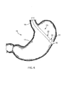
- FIGS. 1-2 depict a medical system 20 for suturing closed a perforation 10 in tissue 12 (see, e.g., FIG. 6 ), constructed in accordance with the teachings of the present invention.
- the medical system 20 generally comprises an endoscope 22, a needle assembly 24 and a medical device 26 adapted for use with the endoscope 22.
- the endoscope 22 may be any scope known to those skilled in the art, and therefore may have various lengths, diameters and functionality.
- the endoscope 22 generally defines a longitudinal axis 14, and a working channel 28 extends longitudinally through the endoscope 22.
- the needle assembly 24 is received within the working channel 28, and as best seen in FIG.
- a needle 30 with a needle lumen 32 receiving one or more tissue anchors 34 having suture 36 connected thereto.
- a stylet 38 or other pushing element is typically fitted within the needle lumen 32 to eject the anchors 34, as is known in the art.
- a needle sheath 40 may also be provided to shield and control exposure of the piercing distal tip of the needle 30.
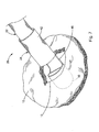
- the medical device 26 generally includes an endcap 42 having a tubular or annular sidewall 44 defining an interior space 46 accessible via a side port 48 for suturing the tissue 12 with the needle assembly 24.
- a proximal portion 46p of the interior space 46 is sized to receive the distal end of the endoscope 22.
- the endcap 42 may be structured to frictionally engage the endoscope 22 for selective retention of the endcap 42 on the endoscope 22, although other means for connecting the endcap 42 to the endoscope 22 may be employed, as is known in the art.
- the endoscope 22 and medical device 26 are therefore adapted to be traversed through the body of a patient in this connected configuration shown in the figures.
- the annular sidewall 44 defines an interior space 46, portions of which include the proximal interior space 46p, an intermediate interior space 46i and a distal interior space 46d. Adjacent the intermediate interior space 44i, the sidewall 42 defines the side port 48 through which the tissue 12 enters the interior space 46.
- the medical device 26 preferably also includes an endwall 50 located at the distal end of the sidewall 44.
- the endwall 50 encloses the distal interior space 46d, and is preferably constructed of an optical-grade plastic that permits the endoscope 22 to visualize through the endcap 42, discussed in greater detail herein.
- the medical device 26 also includes a support rib 52 which bisects the annular sidewall 44 in the distal interior space 46d.
- On one side of the support rib 52 there is an anchor ejection portion 54 of the distal interior space 46d, which is defined by the space between the support rib 52 and sidewall 44.
- the anchor ejection portion 54 of the distal interior space 46d is sized to receive the needle assembly 24, and in particular the needle 30 and the tissue anchor 34.
- the support rib 52 extends from a first position 52a on the sidewall to a second position 52b on the sidewall.
- the support rib 52 and sidewall 44 also define a piercing aperture 56 therebetween, which is the area where the anchor ejection portion 54 meets the intermediate interior space 46i.
- the edge 58 of the support rib 52 defines a support surface, and together with the portion of the sidewall that is exposed by the side port 48, defines an annular support surface for supporting tissue during suturing, as will be described in further detail herein.
- the anchor ejection portion 54 meets the side port 48 over a line, namely the curved line of the piercing aperture 56 defined by the sidewall 44.
- the piercing aperture 56 is semi-circular in shape (although it may have other shapes depending upon the tubular or annular shape of the endcap 42) defined by a largest diameter D 1 and a smallest diameter D 2 .
- the largest diameter D 1 is greater than a length L A of the tissue anchor 34 (shown in FIG. 5 ) while the smallest diameter D 2 is less than the length L A of the tissue anchor 34. This helps to orient the tissue anchor 34 within the anchor ejection portion 54 of the distal interior space 46d.
- both the largest diameter D 1 and the smallest diameter D 2 may be greater than a length L A of the tissue anchor 34.
- the anchor ejection portion 54 of the distal interior space 46d is sized to receive the tissue anchor 34 therein while the tissue anchor 34 is in a lengthwise orientation, meaning its axis 37 extends laterally and is generally perpendicular to the longitudinal axis 14 (i.e. within about 15 degrees of perpendicular). Likewise, the tissue anchor 34 can pass through piercing aperture 56 in its lengthwise orientation. It will be recognized by those skilled in the art that the anchor ejection portion 54 of the distal interior space 46d is in direct and immediate communication with the side port 48 without any intervening structure therebetween, permitting easy passage of the tissue anchor 34.
- the sidewall 44 preferably has a circular cross-sectional shape as shown, and the first and second positions 52a, 52b on the sidewall 44 span an arc A SR of less than about 180 degrees, although in other embodiments A SR can be about 180 degrees.
- the side port 48 spans a second arc A SP which is greater than the first arc A SR bisected by the support rib 52. Accordingly, and as best seen in FIG. 4 , the edge 58 of the support rib 52 and the exposed sidewall 44 define a support surface that has a general D-shape (see, e.g., the un-hatched area shown in FIG. 4 ).
- the support rib 52 also extends longitudinally and engages the endwall 50.
- the longitudinal length of the support rib 52 positions its support surface (namely edge 58) proximate the longitudinal position of the side port 48.
- the endwall 50 has a semi-spherical shape to provide an atraumatic tip to the medical system 20, although the endwall 50 may take other shapes such as flat or conical.
- a majority of the endwall 50 is exposed to the endoscope 22 (see, e.g., FIG. 8 ) thereby permitting visualization through the endwall 50.
- the medical device 26, and in particular endcap 42 is preferably formed of an optical-grade plastic that permits visualization therethrough. Suitable plastics include but are not limited to acrylic, polyacrylates, polyacrylonitrile, polyvinylchloride, polyetherketone, and polyethylene.
- the tissue anchor 34 is preferably of a form where the anchor member is slidable relative to the suture 36.
- One preferred tissue anchor 34 shown in FIG. 5 and includes a wire loop 35 which slidably receives the suture 36. Further details of this and other tissue anchors are disclosed in U.S. Patent Application No. 11/946,565 filed November 25, 2007 and U.S. Patent No. 5,123,914 issued June 23, 1992 .
- FIGS. 6-13 One preferred method for utilizing the medical system 20 and its medical device 26 will now be described with reference to FIGS. 6-13 .
- an upper portion of the gastrointestinal tract 15, such as the esophagus 16 and stomach 17, may be accessed via the mouth (not shown).
- a cutting instrument with or without the aid of an endoscope or other visualization device, may be employed to form an opening 10 in the gastric wall or gastric tissue 12.
- Wire guides, dilators and other medical devices may be employed through the opening 10 to perform a translumenal procedure.
- the medical system 20 may be employed through any natural orifice as (e.g., the mouth, anus, vagina, ears, nose.) as well as intentionally formed orifices such as those made during laparoscopic or similar procedures.
- the bodily opening 10 defined by the tissue of an internal bodily lumen may be intentionally formed or may be naturally occurring, and the internal bodily lumen may comprise a portion of the gastrointestinal tract or any other internal bodily lumen, as will be recognized by those skilled in the art.
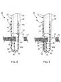
- the medical device 26 and its endcap 42 are fitted on the distal end of the endoscope 22 as shown in FIGS. 1 and 6 .
- the medical system 20 is introduced to a position proximate the opening 10, and the distal portion of the endcap 42 is passed through the opening 10 as shown in FIG. 7 .
- the medical system 20 is manipulated such that the tissue 12 passes through the side port 48 and is positioned within the interior space 46, and in particular the intermediate interior space 46i.
- the visualization element 23 of the endoscope 22 is capable of visualizing the placement of the tissue 12 within the interior space 46, and when there is no tissue 12 within the interior space 46, it can visualize distally beyond the medical device 26 through the endwall 50 of the endcap 42.
- the needle assembly 24 and its needle 30 will be advanced distally through the working channel 28 of the endoscope 22, through the tissue 12, through the piercing aperture 56 and into the anchor ejection portion 54 of the distal interior space 46d.
- the proximal edge 58 of the support rib 52, as well as the exposed portion of the sidewall 44 support the tissue 12 as the needle 30 is advanced therethrough.
- the stylet 38 of needle assembly 24 may be moved relative to the needle 30 to deploy the tissue anchor 34 into the anchor ejection portion 54 of the distal interior space 46d.
- the needle assembly 24 may then be retracted proximally through the working channel 28 of the endoscope 22 such that it is removed from the tissue 12 while leaving the tissue anchor 34 on the distal side of the tissue 12, as shown in FIG. 10 .
- the suture 36 will pass through the tissue 12, and one end of the suture will continue through the working channel 28 and/or the needle 30 for connection to additional tissue anchors 34 and to the proximal end of the medical system 20.
- the other free end of the suture 36 will pass through the side port 48 and along the exterior of the medical system 20 to a location outside of the body, whereby both ends of the suture 36 may be manipulated by the medical professional.
- the tissue anchor 34 is capable of moving through the anchor ejection portion 54 of the distal interior space 46d in its lengthwise orientation shown in FIG. 10 .
- the piercing aperture 56 and the side port 48 permit the tissue anchor 34 to pass directly therethrough such that the medical system 20 may be slid along the periphery of the opening 10 in the tissue 12 to a second site proximate the opening 10.
- the tissue anchor 34 will simply exit the medical device 26 via the side port 48 and remain at the first site where it was deployed.
- the medical system 20 need not be slid along the periphery of the opening 10, but may also be moved laterally away from the tissue 12 so that it exits the interior space 46, whereafter a second site may be identified and targeted for deployment of additional tissue anchors 34.
- tissue anchors 34 may be deployed around the periphery of the opening 10 in the tissue 12, while the suture 36 largely remains on the proximal side of the tissue 12.
- the plurality of tissue anchors 34 may be deployed around the opening 10, such as in a generally circular configuration, although any number and any configuration of anchor deployment may be used, such as zig-zag configurations.
- Both of the free ends 36a, 36b of the suture 36 extend proximally through the bodily lumen and external orifice for individual manipulation by the medical professional to close the opening 10.
- the ends 36a, 36b may be tensioned to reduce the distance between the tissue anchors 34 and compress the tissue 12 around the opening 10 to close the opening 10 in a purse-string fashion, as shown in FIG.
- a suture lock 60 may be employed to connect the ends 36a, 36b of the suture 36 together and maintain the tension thereon, although the suture 36 may also be tied using knots or other techniques or devices as will be readily appreciated by those skilled in the art.
- Several exemplary suture locks are disclosed in U.S. Patent Application Nos. 12/125,525 filed May 22, 2008 and 12/191,001 filed August 13, 2008 .
- the systems and devices may be used on any layer of material (e.g. fabrics, cloth, polymers, elastomers, plastics and rubber) that may or may not be associated with a human or animal body and a bodily lumen.
- the systems and devices can find use in laboratory and industrial settings for placing devices through one or more layers of material that may or may not find application to the human or animal body, and likewise closing holes or perforations in layers of material that are not bodily tissue.
Landscapes
- Health & Medical Sciences (AREA)
- Life Sciences & Earth Sciences (AREA)
- Surgery (AREA)
- General Health & Medical Sciences (AREA)
- Public Health (AREA)
- Veterinary Medicine (AREA)
- Nuclear Medicine, Radiotherapy & Molecular Imaging (AREA)
- Animal Behavior & Ethology (AREA)
- Molecular Biology (AREA)
- Engineering & Computer Science (AREA)
- Biomedical Technology (AREA)
- Heart & Thoracic Surgery (AREA)
- Medical Informatics (AREA)
- Biophysics (AREA)
- Radiology & Medical Imaging (AREA)
- Physics & Mathematics (AREA)
- Pathology (AREA)
- Optics & Photonics (AREA)
- Rheumatology (AREA)
- Surgical Instruments (AREA)
Claims (12)
- Medizinische Vorrichtung (26) zur Verwendung mit einem Endoskop (22) zum Zunähen einer Öffnung (10) in Gewebe (12) unter Verwendung eines Gewebeankers (34), wobei die medizinische Vorrichtung (26) umfasst:eine Endkappe (42), die eine röhrenförmige Form aufweist, die durch eine ringförmige Seitenwand (44) definiert wird, wobei die Seitenwand (44) einen Innenraum (46) definiert;einen Seitenport (48), der durch die ringförmige Seitenwand (44) definiert ist, wobei der Seitenport (48) in Verbindung mit dem Innenraum (46) steht, wobei der Seitenport (48) derart dimensioniert ist, dass er das Gewebe (12) innerhalb des Innenraums (46) aufnimmt und fixiert;eine Stützrippe (52), die innerhalb des Innenraums (46) und distal zu dem Seitenport (48) angeordnet ist, wobei sich die Stützrippe (52) seitlich von einer ersten Position (52a) an der Seitenwand (44) zu einer zweiten Position (52b) an der Seitenwand (44) erstreckt, so dass die Stützrippe (52) einen Abschnitt des Innenraums (46) halbiert, der distal zu dem Seitenport (48) ist, wobei die Stützrippe (52) und die Seitenwand (44) eine dazwischenliegende Durchstechöffnung (56) definieren, wobei die Durchstechöffnung (56) einen maximalen Durchmesser (D1) aufweist, der größer ist als eine Länge des Gewebeankers (34); undeinen Ankerauswerfabschnitt (54) des Innenraums (46) auf einer Seite der Stützrippe (52), der durch den Raum zwischen der Stützrippe (52) und der Seitenwand (44) definiert ist;wobei eine proximale Kante (58) der Stützrippe (52) eine Stützfläche zum Stützen des Gewebes (12) während des Vernähens definiert;
dadurch gekennzeichnet, dassdie proximale Kante (58) der Stützrippe (52) zusammen mit einem Abschnitt der Seitenwand (44), der von dem Seitenport (48) freigelegt ist, eine ringförmige Stützfläche zum Stützen des Gewebes (12) definiert. - Medizinische Vorrichtung (26) nach Anspruch 1, wobei die Durchstechöffnung (56) und der Seitenport (48) an der gleichen seitlichen Seite der Endkappe (42) angeordnet sind.
- Medizinische Vorrichtung (26) nach Anspruch 1, wobei sich die Durchstechöffnung (56) und der Seitenport (48) entlang einer Linie treffen.
- Medizinische Vorrichtung (26) nach Anspruch 1, wobei die Endkappe (42) weiterhin eine distale Stirnwand (50) aufweist, und wobei sich die Stützrippe (52) in Längsrichtung zu der Stirnwand (50) erstreckt.
- Medizinische Vorrichtung (26) nach Anspruch 4, wobei ein Großteil der Stirnwand (50) gegenüber dem Endoskop (22) freigelegt ist und aus einem Material gebildet ist, das ein Durchschauen durch die Stirnwand (50) zulässt.
- Medizinische Vorrichtung (26) nach Anspruch 1, wobei die proximale Kante (58) der Stützrippe (52) koplanar mit dem Abschnitt der Seitenwand (44) ist, der von dem Seitenport (48) freigelegt ist.
- Medizinische Vorrichtung (26) nach Anspruch 1, wobei die Seitenwand (44) eine runde Querschnittsform aufweist und wobei die erste (52a) und die zweite (52b) Position an der Seitenwand (44) einen Kreisbogen (ASR) von weniger als etwa 180 Grad aufspannen.
- Medizinische Vorrichtung (26) nach Anspruch 1, wobei die Seitenwand (44) eine runde Querschnittsform aufweist und wobei die erste (52a) und die zweite (52b) Position an der Seitenwand (44) einen ersten Bogen (ASR) aufspannen und wobei der Seitenport (48) einen zweiten Kreisbogen (ASP) aufspannt, wobei der erste Kreisbogen (ASR) kleiner ist als der zweite Kreisbogen (ASP).
- Medizinische Vorrichtung (26) nach Anspruch 1, wobei der kleinste Durchmesser (D2) der Durchstechöffnung (46) kleiner ist als eine Länge des Gewebeankers (34).
- Medizinisches System (20), das die medizinische Vorrichtung (26) nach einem der vorangehenden Ansprüche umfasst, wobei das medizinische System (20) weiterhin umfasst:ein Endoskop (22), das einen Arbeitskanal (28) aufweist und eine Längsachse (14) definiert; undeine Nadelanordnung (24), die eine Nadel (30), die ein distales Ende und ein Nadellumen (32) definiert, einen Gewebeanker (34), der verschiebbar innerhalb des Nadellumens (32) aufgenommen ist, und einen Faden (36) aufweist, der an dem Gewebeanker (34) befestigt ist, wobei die Nadelanordnung (24) verschiebbar innerhalb des Arbeitskanals (28) des Endoskops (22) aufgenommen ist;wobei sich der Innenraum (46) aus einem proximalen Innenraum (46p), einem mittleren Innenraum (46i) und einem distalen Innenraum (46d) zusammensetzt, wobei der proximale Innenraum (46p) derart dimensioniert ist, dass er ein distales Ende des Endoskops (22) aufnimmt, wobei der Seitenport (48) in Verbindung mit dem mittleren Innenraum (46i) steht, wobei die Stützrippe (52) den distalen Innenraum (46d) halbiert, um den Ankerauswerfabschnitt (54) des distalen Innenraums (46d) zu definieren.
- Medizinisches System (20) nach Anspruch 10, wobei der Ankerauswerfabschnitt (54) des distalen Innenraums (46d) mit dem Arbeitskanal (28) des Endoskops (22) in Umfangsrichtung fluchtet.
- Medizinisches System (20) nach Anspruch 10, wobei der Ankerauswerfabschnitt (54) des distalen Innenraums (46d) ohne eine dazwischenliegende intervenierende Struktur in direkter Verbindung mit dem Seitenport (48) steht.
Applications Claiming Priority (2)
| Application Number | Priority Date | Filing Date | Title |
|---|---|---|---|
| US10933708P | 2008-10-29 | 2008-10-29 | |
| PCT/US2009/062057 WO2010051250A1 (en) | 2008-10-29 | 2009-10-26 | Endoscope endcap for suturing tissue |
Publications (2)
| Publication Number | Publication Date |
|---|---|
| EP2348950A1 EP2348950A1 (de) | 2011-08-03 |
| EP2348950B1 true EP2348950B1 (de) | 2015-03-18 |
Family
ID=41416227
Family Applications (1)
| Application Number | Title | Priority Date | Filing Date |
|---|---|---|---|
| EP09745205.6A Active EP2348950B1 (de) | 2008-10-29 | 2009-10-26 | Endoskopendkappe zum nähen von gewebe |
Country Status (6)
| Country | Link |
|---|---|
| US (1) | US8376932B2 (de) |
| EP (1) | EP2348950B1 (de) |
| JP (1) | JP5485286B2 (de) |
| AU (1) | AU2009308996B2 (de) |
| CA (1) | CA2741530C (de) |
| WO (1) | WO2010051250A1 (de) |
Families Citing this family (11)
| Publication number | Priority date | Publication date | Assignee | Title |
|---|---|---|---|---|
| JP5580828B2 (ja) * | 2008-10-06 | 2014-08-27 | クック メディカル テクノロジーズ エルエルシー | 組織アンカーを安全に配備するための端部キャップ |
| EP2429374B1 (de) * | 2009-05-01 | 2013-09-25 | Cook Medical Technologies LLC | Medizinische vorrichtung für perforationsnaht |
| WO2011112721A1 (en) | 2010-03-09 | 2011-09-15 | University Of Louisville Research Foundation, Inc. | Endoscopic closure device |
| US8771173B2 (en) * | 2010-12-14 | 2014-07-08 | Saint Joseph's Translational Research Institute, Inc. | Access device for surgery |
| CN203468565U (zh) * | 2011-03-10 | 2014-03-12 | 松下电器产业株式会社 | 内窥镜摄像机及内窥镜装置 |
| US20130023904A1 (en) * | 2011-07-20 | 2013-01-24 | Yoshinori Morita | Suturing method |
| CA2952362C (en) | 2014-06-15 | 2023-10-03 | Anchora Medical Ltd. | Apparatus and method for suturing a tissue |
| US9861356B2 (en) | 2014-10-01 | 2018-01-09 | Brainchild Surgical Devices Llc | Suturing device and method |
| US20170046507A1 (en) * | 2015-08-10 | 2017-02-16 | International Business Machines Corporation | Continuous facial recognition for adaptive data restriction |
| DE102016208624B4 (de) * | 2016-05-19 | 2018-02-15 | Universität Ulm | Vorrichtung zur Modifizierung eines Endoskops, modifiziertes Endoskop und seine Verwendung in der gastrointestinalen Endoskopie und in einem Verfahren zur Vernähung einer Wunde |
| CN110461247B (zh) | 2016-11-13 | 2024-02-20 | 安奇拉医疗有限公司 | 微创组织缝合装置 |
Family Cites Families (29)
| Publication number | Priority date | Publication date | Assignee | Title |
|---|---|---|---|---|
| US5059201A (en) | 1989-11-03 | 1991-10-22 | Asnis Stanley E | Suture threading, stitching and wrapping device for use in open and closed surgical procedures |
| GB9405790D0 (en) * | 1994-03-23 | 1994-05-11 | Univ London | Sewing device |
| US7744613B2 (en) | 1999-06-25 | 2010-06-29 | Usgi Medical, Inc. | Apparatus and methods for forming and securing gastrointestinal tissue folds |
| US6358197B1 (en) * | 1999-08-13 | 2002-03-19 | Enteric Medical Technologies, Inc. | Apparatus for forming implants in gastrointestinal tract and kit for use therewith |
| US6719763B2 (en) * | 2000-09-29 | 2004-04-13 | Olympus Optical Co., Ltd. | Endoscopic suturing device |
| US6997931B2 (en) | 2001-02-02 | 2006-02-14 | Lsi Solutions, Inc. | System for endoscopic suturing |
| US8142448B2 (en) * | 2001-11-26 | 2012-03-27 | Olympus Corporation | Endoscopic instruments for suturing tissues in a body cavity |
| US20030225312A1 (en) | 2002-03-18 | 2003-12-04 | Anthony Kalloo | Endoscopic system for treating inside of body cavity |
| US8105342B2 (en) * | 2002-05-08 | 2012-01-31 | Apollo Endosurgery, Inc. | Apparatus for ligating/suturing living tissues and system for resecting/suturing living tissues |
| JP4373146B2 (ja) | 2002-07-11 | 2009-11-25 | オリンパス株式会社 | 内視鏡用縫合装置 |
| WO2004021873A2 (en) * | 2002-09-06 | 2004-03-18 | C.R. Bard, Inc. | Integrated endoscope and accessory treatment device |
| US6908427B2 (en) * | 2002-12-30 | 2005-06-21 | PARÉ Surgical, Inc. | Flexible endoscope capsule |
| AU2003206511A1 (en) | 2003-02-04 | 2004-08-30 | Kiyoshi Hashiba | Endoscopic suturing apparatus |
| MXPA05012303A (es) * | 2003-05-16 | 2006-02-22 | Bard Inc C R | Sistema de suturacion endoscopico de puntadas multiples, de intubacion individual. |
| US7431694B2 (en) | 2003-05-16 | 2008-10-07 | Ethicon Endo-Surgery, Inc. | Method of guiding medical devices |
| US7815565B2 (en) | 2003-05-16 | 2010-10-19 | Ethicon Endo-Surgery, Inc. | Endcap for use with an endoscope |
| JP4217587B2 (ja) | 2003-11-26 | 2009-02-04 | オリンパス株式会社 | 内視鏡用キャップ |
| WO2005065554A1 (ja) * | 2004-01-08 | 2005-07-21 | Olympus Corporation | 吻合器および生体内管腔器官壁部の切除方法 |
| US7211093B2 (en) | 2004-01-14 | 2007-05-01 | Lsi Solutions, Inc. | Sew-right running stitch instrument |
| JP4700384B2 (ja) * | 2004-04-07 | 2011-06-15 | オリンパス株式会社 | 医療用結紮縫合装置及び医療用結紮縫合システム |
| JP4643328B2 (ja) | 2004-04-07 | 2011-03-02 | オリンパス株式会社 | 医療用結紮縫合装置 |
| US8172857B2 (en) | 2004-08-27 | 2012-05-08 | Davol, Inc. | Endoscopic tissue apposition device and method of use |
| JP4302602B2 (ja) | 2004-09-24 | 2009-07-29 | オリンパス株式会社 | 内視鏡用処置具及び内視鏡処置システム並びに支持アダプタ |
| US7645286B2 (en) * | 2005-05-20 | 2010-01-12 | Neotract, Inc. | Devices, systems and methods for retracting, lifting, compressing, supporting or repositioning tissues or anatomical structures |
| US7731727B2 (en) | 2006-04-26 | 2010-06-08 | Lsi Solutions, Inc. | Medical instrument to place a pursestring suture, open a hole and pass a guidewire |
| US20080097152A1 (en) | 2006-07-20 | 2008-04-24 | David Stefanchik | Braided endoscope accessories |
| US8088062B2 (en) | 2007-06-28 | 2012-01-03 | Ethicon Endo-Surgery, Inc. | Interchangeable endoscopic end effectors |
| US8888792B2 (en) | 2008-07-14 | 2014-11-18 | Ethicon Endo-Surgery, Inc. | Tissue apposition clip application devices and methods |
| US8241204B2 (en) | 2008-08-29 | 2012-08-14 | Ethicon Endo-Surgery, Inc. | Articulating end cap |
-
2009
- 2009-10-26 US US12/605,763 patent/US8376932B2/en active Active
- 2009-10-26 WO PCT/US2009/062057 patent/WO2010051250A1/en active Application Filing
- 2009-10-26 AU AU2009308996A patent/AU2009308996B2/en active Active
- 2009-10-26 JP JP2011534660A patent/JP5485286B2/ja active Active
- 2009-10-26 EP EP09745205.6A patent/EP2348950B1/de active Active
- 2009-10-26 CA CA2741530A patent/CA2741530C/en active Active
Also Published As
| Publication number | Publication date |
|---|---|
| JP5485286B2 (ja) | 2014-05-07 |
| CA2741530A1 (en) | 2010-05-06 |
| EP2348950A1 (de) | 2011-08-03 |
| AU2009308996B2 (en) | 2013-05-09 |
| WO2010051250A1 (en) | 2010-05-06 |
| US8376932B2 (en) | 2013-02-19 |
| CA2741530C (en) | 2017-01-24 |
| AU2009308996A1 (en) | 2010-05-06 |
| JP2012507360A (ja) | 2012-03-29 |
| US20100121140A1 (en) | 2010-05-13 |
Similar Documents
| Publication | Publication Date | Title |
|---|---|---|
| EP2348950B1 (de) | Endoskopendkappe zum nähen von gewebe | |
| US8876701B2 (en) | Medical systems, devices and methods for endoscopically suturing perforations | |
| AU2010341614B2 (en) | Medical devices and methods for suturing tissue | |
| EP2222230B1 (de) | Geräte zur abgabe von verankerungsvorrichtungen in die wände von körpergängen | |
| US7967842B2 (en) | Integrated securement and closure apparatus | |
| US11864751B2 (en) | Endoscopic tissue approximation system and methods | |
| US20110093009A1 (en) | Otomy closure device | |
| EP2346411B1 (de) | Endkappe zur sicheren ablage von gewebeankern | |
| CA2586409A1 (en) | Tri-bending sphinctertome | |
| US20070156165A1 (en) | Percutaneous transgastric gastroplication and transgastric minimally invasive surgery | |
| US8152835B2 (en) | Methods for the placement of sutures in tissue | |
| CN212369055U (zh) | 一种腹腔穿刺缝合器的穿刺鞘 |
Legal Events
| Date | Code | Title | Description |
|---|---|---|---|
| PUAI | Public reference made under article 153(3) epc to a published international application that has entered the european phase |
Free format text: ORIGINAL CODE: 0009012 |
|
| 17P | Request for examination filed |
Effective date: 20110517 |
|
| AK | Designated contracting states |
Kind code of ref document: A1 Designated state(s): AT BE BG CH CY CZ DE DK EE ES FI FR GB GR HR HU IE IS IT LI LT LU LV MC MK MT NL NO PL PT RO SE SI SK SM TR |
|
| DAX | Request for extension of the european patent (deleted) | ||
| RAP1 | Party data changed (applicant data changed or rights of an application transferred) |
Owner name: COOK MEDICAL TECHNOLOGIES LLC |
|
| RAP1 | Party data changed (applicant data changed or rights of an application transferred) |
Owner name: COOK MEDICAL TECHNOLOGIES LLC |
|
| 17Q | First examination report despatched |
Effective date: 20140307 |
|
| REG | Reference to a national code |
Ref country code: DE Ref legal event code: R079 Ref document number: 602009030047 Country of ref document: DE Free format text: PREVIOUS MAIN CLASS: A61B0001018000 Ipc: A61B0001000000 |
|
| RIC1 | Information provided on ipc code assigned before grant |
Ipc: A61B 1/00 20060101AFI20140829BHEP Ipc: A61B 17/00 20060101ALN20140829BHEP Ipc: A61B 17/04 20060101ALN20140829BHEP Ipc: A61B 1/018 20060101ALN20140829BHEP |
|
| GRAP | Despatch of communication of intention to grant a patent |
Free format text: ORIGINAL CODE: EPIDOSNIGR1 |
|
| INTG | Intention to grant announced |
Effective date: 20141009 |
|
| RIC1 | Information provided on ipc code assigned before grant |
Ipc: A61B 17/04 20060101ALN20140930BHEP Ipc: A61B 1/00 20060101AFI20140930BHEP Ipc: A61B 1/018 20060101ALN20140930BHEP Ipc: A61B 17/00 20060101ALN20140930BHEP |
|
| GRAS | Grant fee paid |
Free format text: ORIGINAL CODE: EPIDOSNIGR3 |
|
| GRAA | (expected) grant |
Free format text: ORIGINAL CODE: 0009210 |
|
| AK | Designated contracting states |
Kind code of ref document: B1 Designated state(s): AT BE BG CH CY CZ DE DK EE ES FI FR GB GR HR HU IE IS IT LI LT LU LV MC MK MT NL NO PL PT RO SE SI SK SM TR |
|
| REG | Reference to a national code |
Ref country code: GB Ref legal event code: FG4D |
|
| REG | Reference to a national code |
Ref country code: CH Ref legal event code: EP |
|
| REG | Reference to a national code |
Ref country code: IE Ref legal event code: FG4D |
|
| REG | Reference to a national code |
Ref country code: AT Ref legal event code: REF Ref document number: 715992 Country of ref document: AT Kind code of ref document: T Effective date: 20150415 |
|
| REG | Reference to a national code |
Ref country code: DE Ref legal event code: R096 Ref document number: 602009030047 Country of ref document: DE Effective date: 20150430 |
|
| REG | Reference to a national code |
Ref country code: NL Ref legal event code: VDEP Effective date: 20150318 |
|
| REG | Reference to a national code |
Ref country code: NL Ref legal event code: VDEP Effective date: 20150318 |
|
| PG25 | Lapsed in a contracting state [announced via postgrant information from national office to epo] |
Ref country code: SE Free format text: LAPSE BECAUSE OF FAILURE TO SUBMIT A TRANSLATION OF THE DESCRIPTION OR TO PAY THE FEE WITHIN THE PRESCRIBED TIME-LIMIT Effective date: 20150318 Ref country code: FI Free format text: LAPSE BECAUSE OF FAILURE TO SUBMIT A TRANSLATION OF THE DESCRIPTION OR TO PAY THE FEE WITHIN THE PRESCRIBED TIME-LIMIT Effective date: 20150318 Ref country code: NO Free format text: LAPSE BECAUSE OF FAILURE TO SUBMIT A TRANSLATION OF THE DESCRIPTION OR TO PAY THE FEE WITHIN THE PRESCRIBED TIME-LIMIT Effective date: 20150618 Ref country code: LT Free format text: LAPSE BECAUSE OF FAILURE TO SUBMIT A TRANSLATION OF THE DESCRIPTION OR TO PAY THE FEE WITHIN THE PRESCRIBED TIME-LIMIT Effective date: 20150318 Ref country code: HR Free format text: LAPSE BECAUSE OF FAILURE TO SUBMIT A TRANSLATION OF THE DESCRIPTION OR TO PAY THE FEE WITHIN THE PRESCRIBED TIME-LIMIT Effective date: 20150318 |
|
| REG | Reference to a national code |
Ref country code: AT Ref legal event code: MK05 Ref document number: 715992 Country of ref document: AT Kind code of ref document: T Effective date: 20150318 |
|
| REG | Reference to a national code |
Ref country code: LT Ref legal event code: MG4D |
|
| PG25 | Lapsed in a contracting state [announced via postgrant information from national office to epo] |
Ref country code: LV Free format text: LAPSE BECAUSE OF FAILURE TO SUBMIT A TRANSLATION OF THE DESCRIPTION OR TO PAY THE FEE WITHIN THE PRESCRIBED TIME-LIMIT Effective date: 20150318 Ref country code: GR Free format text: LAPSE BECAUSE OF FAILURE TO SUBMIT A TRANSLATION OF THE DESCRIPTION OR TO PAY THE FEE WITHIN THE PRESCRIBED TIME-LIMIT Effective date: 20150619 |
|
| PG25 | Lapsed in a contracting state [announced via postgrant information from national office to epo] |
Ref country code: NL Free format text: LAPSE BECAUSE OF FAILURE TO SUBMIT A TRANSLATION OF THE DESCRIPTION OR TO PAY THE FEE WITHIN THE PRESCRIBED TIME-LIMIT Effective date: 20150318 |
|
| PG25 | Lapsed in a contracting state [announced via postgrant information from national office to epo] |
Ref country code: PT Free format text: LAPSE BECAUSE OF FAILURE TO SUBMIT A TRANSLATION OF THE DESCRIPTION OR TO PAY THE FEE WITHIN THE PRESCRIBED TIME-LIMIT Effective date: 20150720 Ref country code: CZ Free format text: LAPSE BECAUSE OF FAILURE TO SUBMIT A TRANSLATION OF THE DESCRIPTION OR TO PAY THE FEE WITHIN THE PRESCRIBED TIME-LIMIT Effective date: 20150318 Ref country code: RO Free format text: LAPSE BECAUSE OF FAILURE TO SUBMIT A TRANSLATION OF THE DESCRIPTION OR TO PAY THE FEE WITHIN THE PRESCRIBED TIME-LIMIT Effective date: 20150318 Ref country code: EE Free format text: LAPSE BECAUSE OF FAILURE TO SUBMIT A TRANSLATION OF THE DESCRIPTION OR TO PAY THE FEE WITHIN THE PRESCRIBED TIME-LIMIT Effective date: 20150318 Ref country code: ES Free format text: LAPSE BECAUSE OF FAILURE TO SUBMIT A TRANSLATION OF THE DESCRIPTION OR TO PAY THE FEE WITHIN THE PRESCRIBED TIME-LIMIT Effective date: 20150318 Ref country code: SK Free format text: LAPSE BECAUSE OF FAILURE TO SUBMIT A TRANSLATION OF THE DESCRIPTION OR TO PAY THE FEE WITHIN THE PRESCRIBED TIME-LIMIT Effective date: 20150318 |
|
| PG25 | Lapsed in a contracting state [announced via postgrant information from national office to epo] |
Ref country code: AT Free format text: LAPSE BECAUSE OF FAILURE TO SUBMIT A TRANSLATION OF THE DESCRIPTION OR TO PAY THE FEE WITHIN THE PRESCRIBED TIME-LIMIT Effective date: 20150318 Ref country code: PL Free format text: LAPSE BECAUSE OF FAILURE TO SUBMIT A TRANSLATION OF THE DESCRIPTION OR TO PAY THE FEE WITHIN THE PRESCRIBED TIME-LIMIT Effective date: 20150318 Ref country code: IS Free format text: LAPSE BECAUSE OF FAILURE TO SUBMIT A TRANSLATION OF THE DESCRIPTION OR TO PAY THE FEE WITHIN THE PRESCRIBED TIME-LIMIT Effective date: 20150718 |
|
| REG | Reference to a national code |
Ref country code: DE Ref legal event code: R097 Ref document number: 602009030047 Country of ref document: DE |
|
| PG25 | Lapsed in a contracting state [announced via postgrant information from national office to epo] |
Ref country code: IT Free format text: LAPSE BECAUSE OF FAILURE TO SUBMIT A TRANSLATION OF THE DESCRIPTION OR TO PAY THE FEE WITHIN THE PRESCRIBED TIME-LIMIT Effective date: 20150318 |
|
| PLBE | No opposition filed within time limit |
Free format text: ORIGINAL CODE: 0009261 |
|
| STAA | Information on the status of an ep patent application or granted ep patent |
Free format text: STATUS: NO OPPOSITION FILED WITHIN TIME LIMIT |
|
| PG25 | Lapsed in a contracting state [announced via postgrant information from national office to epo] |
Ref country code: DK Free format text: LAPSE BECAUSE OF FAILURE TO SUBMIT A TRANSLATION OF THE DESCRIPTION OR TO PAY THE FEE WITHIN THE PRESCRIBED TIME-LIMIT Effective date: 20150318 |
|
| 26N | No opposition filed |
Effective date: 20151221 |
|
| PG25 | Lapsed in a contracting state [announced via postgrant information from national office to epo] |
Ref country code: SI Free format text: LAPSE BECAUSE OF FAILURE TO SUBMIT A TRANSLATION OF THE DESCRIPTION OR TO PAY THE FEE WITHIN THE PRESCRIBED TIME-LIMIT Effective date: 20150318 |
|
| PG25 | Lapsed in a contracting state [announced via postgrant information from national office to epo] |
Ref country code: LU Free format text: LAPSE BECAUSE OF FAILURE TO SUBMIT A TRANSLATION OF THE DESCRIPTION OR TO PAY THE FEE WITHIN THE PRESCRIBED TIME-LIMIT Effective date: 20151026 |
|
| REG | Reference to a national code |
Ref country code: CH Ref legal event code: PL |
|
| PG25 | Lapsed in a contracting state [announced via postgrant information from national office to epo] |
Ref country code: MC Free format text: LAPSE BECAUSE OF FAILURE TO SUBMIT A TRANSLATION OF THE DESCRIPTION OR TO PAY THE FEE WITHIN THE PRESCRIBED TIME-LIMIT Effective date: 20150318 |
|
| PG25 | Lapsed in a contracting state [announced via postgrant information from national office to epo] |
Ref country code: LI Free format text: LAPSE BECAUSE OF NON-PAYMENT OF DUE FEES Effective date: 20151031 Ref country code: CH Free format text: LAPSE BECAUSE OF NON-PAYMENT OF DUE FEES Effective date: 20151031 |
|
| REG | Reference to a national code |
Ref country code: FR Ref legal event code: ST Effective date: 20160630 |
|
| PG25 | Lapsed in a contracting state [announced via postgrant information from national office to epo] |
Ref country code: FR Free format text: LAPSE BECAUSE OF NON-PAYMENT OF DUE FEES Effective date: 20151102 Ref country code: BE Free format text: LAPSE BECAUSE OF FAILURE TO SUBMIT A TRANSLATION OF THE DESCRIPTION OR TO PAY THE FEE WITHIN THE PRESCRIBED TIME-LIMIT Effective date: 20150318 |
|
| PG25 | Lapsed in a contracting state [announced via postgrant information from national office to epo] |
Ref country code: SM Free format text: LAPSE BECAUSE OF FAILURE TO SUBMIT A TRANSLATION OF THE DESCRIPTION OR TO PAY THE FEE WITHIN THE PRESCRIBED TIME-LIMIT Effective date: 20150318 Ref country code: BG Free format text: LAPSE BECAUSE OF FAILURE TO SUBMIT A TRANSLATION OF THE DESCRIPTION OR TO PAY THE FEE WITHIN THE PRESCRIBED TIME-LIMIT Effective date: 20150318 Ref country code: HU Free format text: LAPSE BECAUSE OF FAILURE TO SUBMIT A TRANSLATION OF THE DESCRIPTION OR TO PAY THE FEE WITHIN THE PRESCRIBED TIME-LIMIT; INVALID AB INITIO Effective date: 20091026 |
|
| PG25 | Lapsed in a contracting state [announced via postgrant information from national office to epo] |
Ref country code: CY Free format text: LAPSE BECAUSE OF FAILURE TO SUBMIT A TRANSLATION OF THE DESCRIPTION OR TO PAY THE FEE WITHIN THE PRESCRIBED TIME-LIMIT Effective date: 20150318 |
|
| PG25 | Lapsed in a contracting state [announced via postgrant information from national office to epo] |
Ref country code: MT Free format text: LAPSE BECAUSE OF FAILURE TO SUBMIT A TRANSLATION OF THE DESCRIPTION OR TO PAY THE FEE WITHIN THE PRESCRIBED TIME-LIMIT Effective date: 20150318 Ref country code: TR Free format text: LAPSE BECAUSE OF FAILURE TO SUBMIT A TRANSLATION OF THE DESCRIPTION OR TO PAY THE FEE WITHIN THE PRESCRIBED TIME-LIMIT Effective date: 20150318 |
|
| PG25 | Lapsed in a contracting state [announced via postgrant information from national office to epo] |
Ref country code: MK Free format text: LAPSE BECAUSE OF FAILURE TO SUBMIT A TRANSLATION OF THE DESCRIPTION OR TO PAY THE FEE WITHIN THE PRESCRIBED TIME-LIMIT Effective date: 20150318 |
|
| P01 | Opt-out of the competence of the unified patent court (upc) registered |
Effective date: 20230602 |
|
| PGFP | Annual fee paid to national office [announced via postgrant information from national office to epo] |
Ref country code: IE Payment date: 20230925 Year of fee payment: 15 Ref country code: GB Payment date: 20230914 Year of fee payment: 15 |
|
| PGFP | Annual fee paid to national office [announced via postgrant information from national office to epo] |
Ref country code: DE Payment date: 20230915 Year of fee payment: 15 |